EP2871150B1 - Filling unit and method for filling an article with a pourable product - Google Patents
Filling unit and method for filling an article with a pourable product Download PDFInfo
- Publication number
- EP2871150B1 EP2871150B1 EP13192230.4A EP13192230A EP2871150B1 EP 2871150 B1 EP2871150 B1 EP 2871150B1 EP 13192230 A EP13192230 A EP 13192230A EP 2871150 B1 EP2871150 B1 EP 2871150B1
- Authority
- EP
- European Patent Office
- Prior art keywords
- filling
- article
- aeriform
- fluidic line
- valve
- Prior art date
- Legal status (The legal status is an assumption and is not a legal conclusion. Google has not performed a legal analysis and makes no representation as to the accuracy of the status listed.)
- Active
Links
Images

Classifications
-
- B—PERFORMING OPERATIONS; TRANSPORTING
- B67—OPENING, CLOSING OR CLEANING BOTTLES, JARS OR SIMILAR CONTAINERS; LIQUID HANDLING
- B67C—CLEANING, FILLING WITH LIQUIDS OR SEMILIQUIDS, OR EMPTYING, OF BOTTLES, JARS, CANS, CASKS, BARRELS, OR SIMILAR CONTAINERS, NOT OTHERWISE PROVIDED FOR; FUNNELS
- B67C3/00—Bottling liquids or semiliquids; Filling jars or cans with liquids or semiliquids using bottling or like apparatus; Filling casks or barrels with liquids or semiliquids
- B67C3/007—Applications of control, warning or safety devices in filling machinery
-
- B—PERFORMING OPERATIONS; TRANSPORTING
- B67—OPENING, CLOSING OR CLEANING BOTTLES, JARS OR SIMILAR CONTAINERS; LIQUID HANDLING
- B67C—CLEANING, FILLING WITH LIQUIDS OR SEMILIQUIDS, OR EMPTYING, OF BOTTLES, JARS, CANS, CASKS, BARRELS, OR SIMILAR CONTAINERS, NOT OTHERWISE PROVIDED FOR; FUNNELS
- B67C3/00—Bottling liquids or semiliquids; Filling jars or cans with liquids or semiliquids using bottling or like apparatus; Filling casks or barrels with liquids or semiliquids
- B67C3/02—Bottling liquids or semiliquids; Filling jars or cans with liquids or semiliquids using bottling or like apparatus
- B67C3/06—Bottling liquids or semiliquids; Filling jars or cans with liquids or semiliquids using bottling or like apparatus using counterpressure, i.e. filling while the container is under pressure
- B67C3/12—Pressure-control devices
-
- B—PERFORMING OPERATIONS; TRANSPORTING
- B67—OPENING, CLOSING OR CLEANING BOTTLES, JARS OR SIMILAR CONTAINERS; LIQUID HANDLING
- B67C—CLEANING, FILLING WITH LIQUIDS OR SEMILIQUIDS, OR EMPTYING, OF BOTTLES, JARS, CANS, CASKS, BARRELS, OR SIMILAR CONTAINERS, NOT OTHERWISE PROVIDED FOR; FUNNELS
- B67C3/00—Bottling liquids or semiliquids; Filling jars or cans with liquids or semiliquids using bottling or like apparatus; Filling casks or barrels with liquids or semiliquids
- B67C3/02—Bottling liquids or semiliquids; Filling jars or cans with liquids or semiliquids using bottling or like apparatus
- B67C3/22—Details
- B67C3/28—Flow-control devices, e.g. using valves
Definitions
- the present invention relates to a filling unit for contact or contactless filling an article with a pourable product, especially a pourable food product.
- the present invention also relates to a filling method for contact or contactless filling an article with the pourable product, especially a pourable food product.
- the filling device is adapted either to fill the article with a carbonated food product, i.e. a food product containing carbon dioxide, according to a contact modality or to fill the article with a still pourable product according a contactless modality.
- a carbonated food product i.e. a food product containing carbon dioxide
- Known article-handling machines comprise a filling station fed with empty articles and adapted to output articles filled with the pourable food product.
- the filling unit substantially comprises a carousel conveyor rotating about a rotation axis, a tank containing the pourable food product, and a plurality of filling devices supported by the carousel conveyor in a position radially external with respect to the rotation axis of the carousel conveyor.
- the carousel is provided with a plurality of support elements for respective articles provided to arrange the mouths of respective articles in a lower position with respect to the respective filling devices and to displace the articles along a circumferential arc trajectory about the above said rotation axis integrally to the respective filling devices.
- Each filling device essentially comprises a fixed body connected to the carousel and a shutter sliding with respect to the fixed body between an open configuration and a closed configuration.
- the shutter when it is arranged in the open configuration, the shutter defines an opening with the fixed body.
- the pourable product thereby flows from the tank to a filling mouth of the relative article passing through the opening.
- the shutter when the shutter is arranged in the closed configuration, it sealingly cooperates with an abutment surface defined by the fixed body, thus preventing the pourable product from flowing from tank towards the mouth of the relative article.
- the body of the filling device is arranged at a given distance from the mouth of the article to be filled.
- the filling device is required to carry out a plurality of additional operations on the articles, in addition to the filling with the pourable food product.
- the articles undergo a pressurization operation before the filling thereof with the pourable food product.
- the empty articles are filled with a pressurized gas, so as to render the pressure inside the articles equal to the pressure of the pourable product, during the filling operation.
- the filling chamber is divided in a upper part filled with the pourable product and a lower part which faces the mouth of the article.
- the filling device shown in US-A-2001/0045242 comprises:
- control valves can be controlled to fluidly connect the return duct with the pressurization chamber, during the filling of the article.
- the shutter In case of filling with carbonated products, the shutter is kept in the closed configuration while the mouth of the article is in tight-fluid contact with the body of the filling device, and the control valves are controlled to allow the flow of the pressurized gas from the upper part of the tank towards the lower part of the filling device.
- the article is pressurized before the filling thereof.
- control valves are controlled to prevent the pressurized gas from flowing towards the filling device, and the shutter is set in the open configuration.
- the food product flows inside the inner volume of the article while the gas contained in the article flows back in the return duct and in the fluidic line towards the pressurization chamber and the upper part of the tank.
- the gas previously contained in the article mixes inside the pressurization chamber and the fluidic line with the gas coming from the tank and that has not yet reached the article.
- the gas that returns back along the return duct has been in contact with the article and, therefore, contains a certain amount of impurities.
- the gas with some impurities coming from the duct contaminates inside the chamber the "clean" pressurized gas coming from the upper part of the tank.
- the pressurized gas which eventually pressurizes the inner volume of the article inevitably contains some impurities.
- the filling device also needs to de-pressurize the article, after that the filling thereof with the food product has been completed.
- EP 1 216 952 A2 discloses a filling device according to the preamble of claim 1.
- the aforementioned object is achieved by the present invention as it relates to a filling device for contact or contactless filling device for filling an article with a pourable product, as defined in claim 1.
- the present invention also relates to a method for contact or contactless filling an article with a pourable product, as defined in claim 12.
- numeral 1 indicates a filling unit for filling articles 2 with a pourable product.
- Filling unit 1 is adapted either to contactless fill article 2 with a still food product or to contact fill article 2 with a carbonated food product, i.e. a food product containing carbon dioxide.
- filling unit 1 essentially comprises ( Figures 5 and 6 ):
- Carousel 3 also includes a tank 6 common to all filling devices 10 and which comprises a lower portion 7 filled with the pourable food product at a pressure higher than environment pressure and an upper portion 8 filled with a gas.
- gas is a pressurization gas, e.g. carbon dioxide, in case of contact filling of carbonated products.
- the gas is flown inside article 2 before the filling thereof, so as to render equal the pressure in the inner volume of articles 2 and the pressure of the pourable product inside portion 7 of tank 6.
- the gas contained in portion 8 is typically air or nitrogen and is flown through portion 8 of tank 6, so as to prevent contaminant substances to enter inside tank 6 and to contaminate the pourable food product.
- Each article 2 comprises ( Figures 1 to 4 ):
- Filling device 10 essentially comprises ( Figures 3 and 4 ) :
- Gripping device 17 is movable together and synchronously with filling device 10 and carousel 3 about axis A.
- gripping device 17 is movable parallel to axis B between:
- gripping device 17 moves from the lowered rest position to the raised operative position at station I and moves from the raised operative position to the lowered rest position at station O.
- Body 19 comprises, in turn, proceeding along axis B:
- filling unit 1 comprises, for each filling device 10, a fluidic line 14 interposed between lower portion 7 of tank 6 and openings 20 of filling devices 10, and along which a flow-sensor 29, a flow-meter in the embodiment shown, is arranged.
- Protrusion 22 is axially interposed between openings 20, 21, proceeding along axis B.
- passage 24 is, in a section orthogonal to axis B, shaped as a circle, the food product creates a cylindrical flow of axis B, during the filling of article 2.
- shutter 16 comprises:
- Plunger 25 is conical of axis B and comprises a conical end on the side of opening 21 shaped correspondingly to the shape of opening 21.
- protrusion 22 is conical of axis B and tapers from opening 20 to opening 21.
- Shutter 16 is movable relative to body 19 and along axis B between:
- the expression contact filling indicates a filling modality, in which article 2 is tight-fluidly pressed against body 19 of filling device 10 whereas the expression contactless filling indicates a filling modality, in which article 2 is spaced along axis B from body 19 of filling device 10.
- the food product is prevented from contacting the outer environment in case of contact filling whereas the food product contacts the outer environment in case of contactless filling.
- plunger 25 when shutter 16 is in the open configuration, plunger 25 is spaced from protrusion 22 and leaves free passage 24.
- plunger 25 abuts against protrusion 22 and seals passage 24.
- mouth 11 of article 2 is tight-fluidly pressed against opening 21 of filling device 10 in case of contact filling, when gripping device 17 is in the raised position.
- mouth 11 of article 2 is spaced along axis B from opening 21 of filling device 10 in case of contactless filling, when gripping device 17 is in the raised position.
- Body 19 also comprise a plurality, three in the embodiment shown, of ducts 18a, 18b, 18c (only schematically shown in Figures 1 and 2 ), which extend eccentrically to and on one side only of axis B and are arranged radially outer than shutter 16 with respect to axis B (see Figures 3 and 4 ).
- each duct 18a, 18b, 18c comprises an end opening 30. Openings 30 open inside body 19 in a position axially interposed along axis B between protrusion 22 and opening 21, i.e. inside cavities 31.
- openings 30 are in fluid connection with mouth 11 of article 2, even when shutter 16 is in the closed configuration.
- each duct 18a, 18b, 18c comprises:
- Portion 27 converge towards axis B on the opposite side of portion 26, in the embodiment shown.
- Portion 28 is, in the embodiment shown, radial to axis B.
- Filling unit 1 also comprises ( Figures 1 and 2 ) a plurality of fluidic lines 35, which are adapted to selectively convey the pressurization gas from upper portion 8 of tank 6 inside the inner volume of relative articles 2, in case of contact filling.
- fluidic lines 35 comprise:
- Filling unit 1 also comprises:
- Valve 41 may be selectively arranged in:
- Each valve 42 may be selectively arranged in:
- Filling unit 1 also comprises a control unit 45 (only schematically shown in Figures 1 and 2 ) configured to valves 41, 42 and shutters 16 of filling device 10 in such a way to pressurize articles 2 with gas contained in upper portion 7 of tank 6, before the contact filling of articles 2 with carbonated food product.
- a control unit 45 (only schematically shown in Figures 1 and 2 ) configured to valves 41, 42 and shutters 16 of filling device 10 in such a way to pressurize articles 2 with gas contained in upper portion 7 of tank 6, before the contact filling of articles 2 with carbonated food product.
- control unit 45 is configured, in case of contact filling of articles 2 with carbonated food product, to:
- Filling unit 1 also comprises ( Figures 1 and 2 ):
- Filling unit 1 comprises, for each filling device 10 and corresponding article 2,:
- each fluidic line 35 is fluidly isolated from corresponding fluidic line 44, i.e. the gas coming out from each article 2 along respective fluidic line 44 is prevented from reaching corresponding fluidic lines 35.
- fluidic lines 35, 44 are not required to be physically isolated from one another, but a preferential flow of the gas contained in upper portion 8 of tank 6 is established (as indicated by arrows in Figures 1 and 2 ):
- fluidic lines 44 comprises, proceeding from the inner volume of relative articles 2 towards discharge 55,:
- Each valve 46 is, in the embodiment shown, interposed along a relative portion 47 of the corresponding fluidic line 44.
- Filling unit 1 comprises a duct 60, which is interposed between pressurization chamber 40 and portion 49, and is connected to portion 49 at a connection point 61.
- common portion 49 of fluidic lines 44 comprises, proceeding from return gas chamber 48 to discharge 55,:
- Filling unit 1 further comprises:
- Means 62, 63 are throttlings, in the embodiment shown.
- Pressurization chamber 40 is at a first value of pressure
- return gas chamber 48 is at a second value of pressure
- discharge 55 is a third value of pressure.
- the first value of pressure is greater than the second value of pressure, and the second value of pressure is greater than the third value of pressure.
- the difference of pressure between pressurization chamber 40 and return gas chamber 48 is generated by the distributed hydraulic losses along segment 56 and duct 60, and by the concentrated hydraulic losses 62, 63.
- the gas preferentially moves from chamber 40 to inner volumes of articles 2 before the contact filling thereof, and from the inner volumes of article 2 to return gas chamber 48 and from return gas chamber 48 to discharge 55 before the contact filling of articles 2.
- Filling unit 1 also comprises a modulating valve 59 which is interposed along fluidic line 44 and adapted to generate a counter-pressure at the end of fluidic line 44.
- modulating valve 59 is interposed along portion 49 of filling line 44.
- control unit 45 is programmed for controlling valves 39, 41 in such a way that a substantially constant amount of gas passes through portion 8 of tank 6, thus ensuring the asepticity of the food product contained inside portion 7 of tank 6.
- control unit 45 is programmed to set, during the contactless filling of articles 2, corresponding valves 42 in the respective open configuration, so as to allow the gas coming out along fluidic line 35 to discharge from opening 30 of duct 18a inside cavities 31 and, then, inside, the outer environment ( Figure 3 ).
- the gas coming from upper portion 8 of tank 6 is discharged in the area between openings 21 of filling devices 10 and relative mouths 11 of articles 2, which are arranged at a given distance along axis B from respective filling devices 10.
- control unit 45 is also programmed to set, during the contactless filling of articles 2, also corresponding valves 46 in the respective open configurations, so as to allow the gas coming out along fluidic line 35 to discharge from openings 30 of ducts 18b inside cavities 31 and, then, inside the outer environment through openings 21 ( Figure 3 ).
- the gas coming from upper portion 8 of tank 6 is discharged in the area between openings 21 of filling devices 10 and relative mouths 11 of articles 2, which are arranged at a given distance along axis B from respective filling devices 10.
- filling unit 1 comprises:
- each fluidic line 70 extends between opening 32 of duct 18c to a drain 80 at the atmospheric pressure.
- Fluidic lines 70 comprise, proceeding from opening 30 of ducts 18c to drain 80,:
- Valves 75 are interposed between ducts 18c and respective portions 71.
- Control unit 45 is programmed for:
- pressurization chamber 40, return gas chamber 48 and de-pressurization chamber 72 are annular about axis A.
- valves 42, 46, 75 are on-off valves.
- filling unit 1 will be firstly described with reference to a contact filling operation with a carbonated product and with reference to only one filling device 10 and respective only one article 2 and only one gripping device 17, and to only one respective filling line 35, 44, 70 ( Figures 1 and 3 ).
- Portion 8 of tank 6 is filled with a pressurization gas, e.g. carbon dioxide while portion 7 of tank 6 is filled with the food product with which article 2 will be filled.
- a pressurization gas e.g. carbon dioxide
- portion 7 of tank 6 is filled with the food product with which article 2 will be filled.
- the pressure of the food product inside portion 7 of tank 6 is greater than the environment pressure.
- Carousel 3 is fed with empty article 2 at inlet station I, advances it along path P along which article 2 is filled with the carbonated food product and discharges the filled article 2 at outlet station O.
- Gripping device 17 synchronously rotates about axis B integrally with filling device 10.
- gripping device 17 grips neck 12 of article 2 and moves from the lowered position to raised position at station I, and from the raised position to the lowered position at station O.
- mouth 11 of article 2 When article 2 is in the raised position, mouth 11 of article 2 is sealingly pressed against body 19 of filling device 10. Accordingly, mouth 11 is fluidly connected to opening 21 of filling device 10 and with openings 32 of ducts 18a, 18b, 18c.
- filling device 10 carries out on article 2 the subsequently following operations:
- control unit 45 sets valve 41 in the open configuration and sets shutter 16 and valves 42, 46 and 75 in respective closed configurations.
- control unit 45 sets valve 42 in the open configuration, thus allowing the pressurizing gas contained in portion 8 of tank 6 to flow along fluidic line 35.
- the pressurizing gas flows from portion 8 to pressure chamber 40 along portion 36 of fluidic line 35, and from pressure chamber 40 to opening 30 of ducts 18a along portion 37 and duct 18a of the fluidic line 35.
- opening 30 of duct 18a and the inner volume of article 2 are in fluidic connection with cavity 31, when shutter 16 is in the closed configuration and mouth 11 of article 2 is pressed against body 19 of filling device 10, the pressurizing gas can fill and pressurize the inner volume of article 2.
- control unit 45 sets valves 41, 42 in the closed configuration, and sets valve 46 and shutter 16 of filling device 10 in the respective open configuration.
- the gas contained inside the inner volume of article 2 enters opening 30 of duct 18b, flows along ducts 18b, portion 47, return chamber 48 and portion 49, and reaches discharge 55.
- return gas chamber 48 is kept at the second pressure value, which is lower than the first pressure value at which pressurization chamber 40 is kept.
- the difference between the first pressure value and the second pressure value is kept constant.
- the gas coming out from the inner volume of article 2 is substantially prevented from flowing along duct 60 and, therefore, from reaching pressure chamber 40, as indicated in Figure 1 .
- control unit 45 sets shutter 16 and valve 42 in the closed configuration and, subsequently, sets valve 75 in the open configuration.
- head-space 85 of article 2 can flow along fluidic line 70 and reach de-pressurization chamber. 72 and, then, discharge 55. In this way, head-space 85 of article 2 is de pressurized to the environment pressure.
- Filled article 2 with head-space at the environment pressure can be now discharged at station O, without risk of foaming of the food product and/or explosion of article 2.
- filling unit 1 will be now described with reference to a contactless filling operation with a still product and with reference to only one filling device 10 and respective only one article 2, and to only one respective filling line 35, 44, 70 ( Figures 2 and 4 ).
- portion 8 of tank 6 is filled with a gas, i.e. carbon dioxide or nitrogen, while portion 7 of tank 6 is filled with the food product with which article 2 will be filled.
- a gas i.e. carbon dioxide or nitrogen
- Carousel 3 is fed with empty article 2 at inlet station I, advances it along path P along which article 2 is filled with the carbonated food product and discharges the filled article 2 at outlet station O.
- gripping device 17 rotates about axis A and grips neck 12 of article 2 and moves from the lowered position to raised position at station I, and from the raised position to the lowered position at station O.
- mouth 11 of article 2 is spaced along axis B from body 19 of filling device 10. Accordingly, openings 30 of ducts 18a, 18b, 18c and cavities 31 are in fluid contact with the environment surrounding filling device 10.
- Control unit 45 sets shutter 16 in the open configuration, and sets valves 41, 46 and 75 in the respective closed configurations.
- shutter 16 is spaced along axis B from protrusion 22 and the food product is free to pass through passage 24 and opening 21. The food product, then, fall for gravity inside empty article 2.
- control unit 45 sets shutter 16 in the closed configuration.
- control unit 45 controls valves 39, 41, so as to generate a continuous constant flow of gas through portion 8 of tank 6 and along portion 36 of fluidic line 35. That flow prevents contaminant agents from entering inside portion 7 of tank 6 and contaminating the food product.
- control unit 45 sets valve 42 in the respective open configuration.
- control unit 45 also sets valve 46 in the respective open configuration, in order to discharge the gas coming out from portion 8 of tank 6.
- fluidic lines 44 are distinct from fluidic lines 35 and discharge return gas in discharge 55 distinct from tank 6, in case of contact filling of article 2 with carbonated product.
- the return gas coming out for articles 2 is prevented from mixing with the gas coming out from portion 8 of tank 6 and intended to pressurize articles 2.
- fluidic lines 35, 44 are not physically isolated, but are connected by duct 60.
- duct 60 together with hydraulic losses along 56, 57 is effective in keeping a constant pressure difference between the higher first pressure value in pressure chamber 40 and the lower second pressure value in return chamber 48, regardless the punctual values of the first pressure and the second pressure values.
- the distributed hydraulic losses along duct 60 and segment 56 as well as the concentrated hydraulic losses 62, 63 substantially prevent, in case of contact filling, the gas present in chamber 40 to move towards chamber 48 and vice-versa.
- a preferential flow of gas intended to pressurize articles 2 is established from portion 8 of tank 6 to the inner volume of articles 2 during the pressurization of articles 2 and a preferential flow of return gas is established from the inner volume of articles 2 towards discharge 55 during the filling step, without any mixing between the two flows (as shown by the arrows in Figure 1 ).
- the continuous flow of gas through portion 8 of tank 6 is discharged, by suitably controlling valves 42, 46, in the area between opening 21 of body 19 and mouth 11 of article 2.
- the pressurization and/or de-pressurization step of article 2 could not be present, in case of contact filling of article 2 with carbonated products.
- control unit 45 can set valves 42 and/or valves 46 in the respective open configurations, either with respective shutters 16 in the respective closed configurations or with respective shutters 16 in the respective open configurations.
Landscapes
- Filling Of Jars Or Cans And Processes For Cleaning And Sealing Jars (AREA)
- Devices For Dispensing Beverages (AREA)
- Filling Or Discharging Of Gas Storage Vessels (AREA)
Description
- The present invention relates to a filling unit for contact or contactless filling an article with a pourable product, especially a pourable food product.
- The present invention also relates to a filling method for contact or contactless filling an article with the pourable product, especially a pourable food product.
- In greater detail, the filling device is adapted either to fill the article with a carbonated food product, i.e. a food product containing carbon dioxide, according to a contact modality or to fill the article with a still pourable product according a contactless modality.
- Known article-handling machines comprise a filling station fed with empty articles and adapted to output articles filled with the pourable food product.
- The filling unit substantially comprises a carousel conveyor rotating about a rotation axis, a tank containing the pourable food product, and a plurality of filling devices supported by the carousel conveyor in a position radially external with respect to the rotation axis of the carousel conveyor.
- In greater detail, the carousel is provided with a plurality of support elements for respective articles provided to arrange the mouths of respective articles in a lower position with respect to the respective filling devices and to displace the articles along a circumferential arc trajectory about the above said rotation axis integrally to the respective filling devices.
- Each filling device essentially comprises a fixed body connected to the carousel and a shutter sliding with respect to the fixed body between an open configuration and a closed configuration.
- In greater detail, when it is arranged in the open configuration, the shutter defines an opening with the fixed body. The pourable product thereby flows from the tank to a filling mouth of the relative article passing through the opening.
- Differently, when the shutter is arranged in the closed configuration, it sealingly cooperates with an abutment surface defined by the fixed body, thus preventing the pourable product from flowing from tank towards the mouth of the relative article.
- In case of contact filling of carbonated products, the mouth of each article is tight-fluid pressed against the body of the respective filling device. In this way, the carbon dioxide contained in the food product is prevented from escaping from the article in the environment.
- Differently, in case of contactless filling of still products, the body of the filling device is arranged at a given distance from the mouth of the article to be filled.
- Furthermore, in the case of contact filling with carbonated food products, the filling device is required to carry out a plurality of additional operations on the articles, in addition to the filling with the pourable food product.
- In greater detail, the articles undergo a pressurization operation before the filling thereof with the pourable food product. Still more precisely, the empty articles are filled with a pressurized gas, so as to render the pressure inside the articles equal to the pressure of the pourable product, during the filling operation.
- Furthermore, due to the fact that the inner volume of each article is in tight-fluid contact with the body of the respective filling device, the latter is required to allow the gas contained in the articles to escape during the filling of the articles.
- In order to meet all these needs, filling devices are known, for example from
US-A-2001/0045242 , which comprises: - a filling chamber defined by the body and fluidly connected to a lower portion of the tank filled with the pourable food product; and
- a return duct surrounded by the filling chamber and which opens towards the mouth of the article.
- When the shutter is in the closed configuration, the filling chamber is divided in a upper part filled with the pourable product and a lower part which faces the mouth of the article.
- Furthermore, the filling device shown in
US-A-2001/0045242 comprises: - a fluidic line which extends from an upper portion of the tank filled with a pressurized gas, e.g. carbon dioxide or nitrogen dioxide, to the lower part of the filling chamber of the filling device;
- a pressurization chamber, which is interposed along the fluidic line; and
- a plurality of control valves, which can be controlled to fluidly connect the pressurization chamber with the lower part of the filling chamber before the filling of the article.
- Furthermore, the control valves can be controlled to fluidly connect the return duct with the pressurization chamber, during the filling of the article.
- In case of filling with carbonated products, the shutter is kept in the closed configuration while the mouth of the article is in tight-fluid contact with the body of the filling device, and the control valves are controlled to allow the flow of the pressurized gas from the upper part of the tank towards the lower part of the filling device.
- In this way, the article is pressurized before the filling thereof.
- At this stage, the control valves are controlled to prevent the pressurized gas from flowing towards the filling device, and the shutter is set in the open configuration.
- Accordingly, the food product flows inside the inner volume of the article while the gas contained in the article flows back in the return duct and in the fluidic line towards the pressurization chamber and the upper part of the tank.
- As a result, during the filling of the article, the gas previously contained in the article mixes inside the pressurization chamber and the fluidic line with the gas coming from the tank and that has not yet reached the article.
- The gas that returns back along the return duct has been in contact with the article and, therefore, contains a certain amount of impurities. As a result, the gas with some impurities coming from the duct contaminates inside the chamber the "clean" pressurized gas coming from the upper part of the tank.
- Accordingly, the pressurized gas which eventually pressurizes the inner volume of the article inevitably contains some impurities.
- There is, therefore, the risk of contaminating the article during the pressurization thereof, thus generating the risk of contaminating also the food product with which the article will be subsequently filled.
- A need is felt within the industry to reduce as far as possible that risk of contaminating the food product.
- Furthermore, the filling device also needs to de-pressurize the article, after that the filling thereof with the food product has been completed.
- A need is felt within the industry to reduce as far as possible the risk that the gas coming out from the articles contaminates the gas which eventually will be injected in the articles.
-
EP 1 216 952 A2 discloses a filling device according to the preamble of claim 1. - It is an object of the present invention to provide a filling device for contact or contactless filling an article with a pourable product, which allows to easily and cost-effectively meet at least one of the above said needs.
- The aforementioned object is achieved by the present invention as it relates to a filling device for contact or contactless filling device for filling an article with a pourable product, as defined in claim 1.
- The present invention also relates to a method for contact or contactless filling an article with a pourable product, as defined in
claim 12. - One preferred embodiment is hereinafter disclosed for a better understanding of the present invention, by way of non-limitative example and with reference to the accompanying drawings, in which:
-
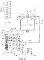
Figure 1 shows a schematic view of a filling unit according to the present invention during a contact filling operation, with parts removed for clarity; -
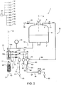
Figure 2 shows in section some components of the filling unit ofFigure 1 during the contactless filling operation, with parts removed for clarity; -
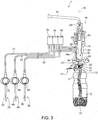
Figure 3 shows a schematic view of the filling unit ofFigure 1 during the contact filling operation, with parts removed for clarity; -
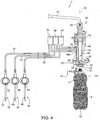
Figure 4 shows in section some components of the filling unit ofFigures 1 to 3 during the contact filling operation, with parts removed for clarity; -
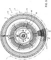
Figure 5 is a top view of the filling unit ofFigures 1 to 4 ; and -
Figure 6 is a perspective view of the filling unit ofFigures 1 to 5 , with parts removed for clarity. - With reference to
Figures 1 to 6 , numeral 1 indicates a filling unit for fillingarticles 2 with a pourable product. - Filling unit 1 is adapted either to
contactless fill article 2 with a still food product or to contact fillarticle 2 with a carbonated food product, i.e. a food product containing carbon dioxide. - In greater detail, filling unit 1 essentially comprises (
Figures 5 and6 ): - a
carousel 3 rotating about an axis A, which is vertical in the case shown, along an arc-shaped path P extending from an input station I to an output station O; and - a plurality of
filling devices 10 adapted to fillrespective articles 2 with the pourable food product and supported by a peripheral edge external to axis A ofcarousel 3. - Carousel 3 also includes a
tank 6 common to allfilling devices 10 and which comprises alower portion 7 filled with the pourable food product at a pressure higher than environment pressure and anupper portion 8 filled with a gas. - In particular, gas is a pressurization gas, e.g. carbon dioxide, in case of contact filling of carbonated products. In this case, the gas is flown inside
article 2 before the filling thereof, so as to render equal the pressure in the inner volume ofarticles 2 and the pressure of the pourable product insideportion 7 oftank 6. - In case of contactless filling of still products, the food product contacts the outer environment. Accordingly, it is necessary to ensure the asepticity of the food product. To this end, the gas contained in
portion 8 is typically air or nitrogen and is flown throughportion 8 oftank 6, so as to prevent contaminant substances to enter insidetank 6 and to contaminate the pourable food product. - Each
article 2 comprises (Figures 1 to 4 ): - a
mouth 11 adapted to allow the filling ofarticle 2 by means of filling unit 1 and the following pouring of the food product fromarticle 2; - a
neck 12 arranged immediately belowmouth 11; and - a
bottom wall 13 opposite tomouth 11. - For simplicity, the following description will refer to only one
filling device 10 and torelative article 2, asdevices 10 are identical to one another. - Filling
device 10 essentially comprises (Figures 3 and4 ) : - a
frame 15 fitted tocarousel 3; - a
hollow body 19 which is defined byframe 15 and which extends about an axis B parallel to and staggered from axis A; - a
shutter 16 movable along axis B insidebody 19; and - a
gripping device 17 movable along axis B towards and away fillingdevice 10 and configured to gripneck 12 ofarticle 2. - Gripping
device 17 is movable together and synchronously with fillingdevice 10 andcarousel 3 about axis A. - Furthermore, gripping
device 17 is movable parallel to axis B between: - a lowered rest position (not-shown); and
- a raised operative position, in which
article 2 undergoes a certain number of operations (shown inFigures 3 and4 ).
- a raised operative position, in which
- Still more precisely, gripping
device 17 moves from the lowered rest position to the raised operative position at station I and moves from the raised operative position to the lowered rest position at station O. -
Body 19 comprises, in turn, proceeding along axis B: - an
opening 20, which is fluidly connected withlower portion 7 oftank 3; - an
annular protrusion 22, which protrudes towards axis B and defines a conical passage 24 (shown inFigure 3 ) ;- an
opening 21, which is opposite to opening 20, which facesmouth 11 ofarticle 2 and through which the food product passes during the filling ofarticle 2; and
- an
- a
cavity 31 which is interposed along axis B betweenprotrusion 22 andopening 21, and which is bounded, on the opposite side ofprotrusion 22, by opening 21. - In particular, filling unit 1 comprises, for each filling
device 10, afluidic line 14 interposed betweenlower portion 7 oftank 6 andopenings 20 of fillingdevices 10, and along which a flow-sensor 29, a flow-meter in the embodiment shown, is arranged. -
Protrusion 22 is axially interposed betweenopenings - Due to the fact that
passage 24 is, in a section orthogonal to axis B, shaped as a circle, the food product creates a cylindrical flow of axis B, during the filling ofarticle 2. - In the embodiment shown,
shutter 16 comprises: - a
stem 23 which receives a force along axis B; and - a
plunger 25 which is arranged at an end ofstem 23 arranged on the side ofopening 21. -
Plunger 25 is conical of axis B and comprises a conical end on the side of opening 21 shaped correspondingly to the shape ofopening 21. - Furthermore,
protrusion 22 is conical of axis B and tapers from opening 20 toopening 21. -
Shutter 16 is movable relative tobody 19 and along axis B between: - an open configuration (shown in
Figure 3 ), in which it allows the fluidic connection betweenlower portion 7 oftank 6 andopening 21, thus allowing the filling ofarticle 2 with the food product; and - a closed configuration (shown in
Figure 4 ), in which it prevents the fluidic connection betweenlower portion 7 oftank 6 andopening 21. - In the present description, the expression contact filling indicates a filling modality, in which
article 2 is tight-fluidly pressed againstbody 19 of fillingdevice 10 whereas the expression contactless filling indicates a filling modality, in whicharticle 2 is spaced along axis B frombody 19 of fillingdevice 10. - In this way, the food product is prevented from contacting the outer environment in case of contact filling whereas the food product contacts the outer environment in case of contactless filling.
- In the embodiment shown, when
shutter 16 is in the open configuration,plunger 25 is spaced fromprotrusion 22 and leavesfree passage 24. - On the contrary, when
shutter 16 is in the closed configuration,plunger 25 abuts againstprotrusion 22 and sealspassage 24. - Furthermore,
mouth 11 ofarticle 2 is tight-fluidly pressed against opening 21 of fillingdevice 10 in case of contact filling, when grippingdevice 17 is in the raised position. - On the contrary,
mouth 11 ofarticle 2 is spaced along axis B from opening 21 of fillingdevice 10 in case of contactless filling, when grippingdevice 17 is in the raised position. -
Body 19 also comprise a plurality, three in the embodiment shown, ofducts Figures 1 and2 ), which extend eccentrically to and on one side only of axis B and are arranged radially outer thanshutter 16 with respect to axis B (seeFigures 3 and4 ). - In detail, each
duct end opening 30.Openings 30 openinside body 19 in a position axially interposed along axis B betweenprotrusion 22 andopening 21, i.e. insidecavities 31. - In this way,
openings 30 are in fluid connection withmouth 11 ofarticle 2, even whenshutter 16 is in the closed configuration. - In the embodiment shown, each
duct - a
main portion 26 extending parallel to axis B; - an
end portion 27, which is housed insideprotrusion 22 and defines opening 30; and - an
end portion 28, which is opposite toportion 26 and defines anopening 32, the function of which will be explained in the following of the present description. -
Portion 27 converge towards axis B on the opposite side ofportion 26, in the embodiment shown. -
Portion 28 is, in the embodiment shown, radial to axis B. - Filling unit 1 also comprises (
Figures 1 and2 ) a plurality offluidic lines 35, which are adapted to selectively convey the pressurization gas fromupper portion 8 oftank 6 inside the inner volume ofrelative articles 2, in case of contact filling. - Still more precisely,
fluidic lines 35 comprise: - a
common portion 36, which originates fromportion 8 oftank 6 and which is common to all fillingdevices 10; - a
pressurization chamber 40, which is common to all fillingdevices 10; -
relative portions 37, which are associated torespective filling devices 10 and interposed betweenchamber 40 andopenings 32 ofrelative duct 18a; and -
relative ducts 18a associated torespective filling devices 10, which are in fluidic connection with the inner volumes ofrespective articles 2, in case of contact filling thereof. - Filling unit 1 also comprises:
- a
valve 41 common to all thefilling devices 10 and interposed alongportion 36 of fillinglines 35 betweenupper portion 8 andchamber 40; and - a plurality of
valves 42 associated torelative filling devices 10 and interposed, each, alongportion 37 of relativefluidic line 35. -
Valve 41 may be selectively arranged in: - an open configuration, in which it allows the gas contained in
upper portion 8 oftank 6 to flow alongportion 36 and towardschamber 40; and - a closed configuration, in which it prevents the gas contained in
upper portion 8 oftank 6 from flowing alongportion 36 and towardschamber 40. - Each
valve 42 may be selectively arranged in: - an open configuration, in which it allow the gas contained in
upper portion 8 oftank 6 to flow fromchamber 40 towardsrelative duct 18a and, therefore,relative article 2; and - a closed configuration, in which it prevents the gas contained in
upper portion 8 oftank 6 from flowing fromchamber 40 towardsrelative duct 18a and, therefore,relative article 2. - Filling unit 1 also comprises a control unit 45 (only schematically shown in
Figures 1 and2 ) configured tovalves shutters 16 of fillingdevice 10 in such a way to pressurizearticles 2 with gas contained inupper portion 7 oftank 6, before the contact filling ofarticles 2 with carbonated food product. - To this end,
control unit 45 is configured, in case of contact filling ofarticles 2 with carbonated food product, to: - keep
shutters 16 of each fillingdevice 10 in respective closed configuration; and - set
valves upper portion 8 oftank 6 to flow alongfluidic lines 35 and to reachopenings 20 andmouths 11 ofarticles 2 to be filled. - Filling unit 1 also comprises (
Figures 1 and2 ): - a
duct 38 for feedingupper portion 8 oftank 6 with the gas; and - a
valve 39 arranged alongduct 38 upstream oftank 6 and controllable to adjust the amount of gas which enterstank 6. - Filling unit 1 comprises, for each filling
device 10 andcorresponding article 2,: - a plurality of
fluidic lines 44 for allowing the escaping of the gas contained insiderespective articles 2 during the contact filling thereof, which are distinct fromfluidic lines 35, and extends from inner volume ofarticle 2 to adischarge 55 distinct fromtank 6; and - a plurality of
valves 46, which may be selectively set in respective open configurations in which they allow the gas contained in the inner volumes ofarticles 2 to flow along respectivefluidic lines 44 or in respective closed configurations in which they prevent the gas contained inarticles 2 from flowing along respectivefluidic lines 44; - In greater detail, in case of contact filling of
articles 2, eachfluidic line 35 is fluidly isolated from correspondingfluidic line 44, i.e. the gas coming out from eacharticle 2 along respectivefluidic line 44 is prevented from reaching corresponding fluidic lines 35. - As it will be evident from the following of the present description,
fluidic lines upper portion 8 oftank 6 is established (as indicated by arrows inFigures 1 and2 ): - from
portion 8 oftank 6 towards inner volume ofarticles 2 along respectivefluidic lines 35 before the contact filling ofarticles 2; and - from inner volume of
articles 2 towardsdischarge 55 and along respectivefluidic lines 44 during the contact filling ofarticles 2. - In greater detail,
fluidic lines 44 comprises, proceeding from the inner volume ofrelative articles 2 towardsdischarge 55,: -
relative ducts 18b ofrespective filling device 10 and which are in fluidic communication with the inner volume ofrelative articles 2, in case of contact filling; -
relative portions 47 associated torespective filling devices 10 and which originates fromopenings 32 ofrelative ducts 18b; - a
return gas chamber 48, which is common to all fillingdevices 10; and - a
portion 49, which is common to all fillingdevices 10 and which extends fromreturn gas chamber 48 to discharge 55. - Each
valve 46 is, in the embodiment shown, interposed along arelative portion 47 of the correspondingfluidic line 44. - Filling unit 1 comprises a
duct 60, which is interposed betweenpressurization chamber 40 andportion 49, and is connected toportion 49 at aconnection point 61. - Still more precisely,
common portion 49 offluidic lines 44 comprises, proceeding fromreturn gas chamber 48 to discharge 55,: - a
segment 56 which extends fromreturn gas chamber 48 toconnection point 61; and - a
segment 57 which extends fromconnection point 61 anddischarge 55. - Filling unit 1 further comprises:
- a means to create hydraulic loss, respectively a concentrated
hydraulic loss 62 arranged alongsegment 56 offluidic line 44; and - a means to create hydraulic loss, respectively a concentrated
hydraulic loss 63 arranged alongduct 60. - Means 62, 63 are throttlings, in the embodiment shown.
-
Pressurization chamber 40 is at a first value of pressure, returngas chamber 48 is at a second value of pressure anddischarge 55 is a third value of pressure. - The first value of pressure is greater than the second value of pressure, and the second value of pressure is greater than the third value of pressure.
- The difference of pressure between
pressurization chamber 40 and returngas chamber 48 is generated by the distributed hydraulic losses alongsegment 56 andduct 60, and by the concentratedhydraulic losses - As a result of this difference of pressure between
pressurization chamber 40 and returngas chamber 48, during contact filling of articles 2 (Figures 1 and3 ), the gas contained inreturn gas chamber 48 is substantially prevented from moving alongduct 60 and is substantially forced to move alongsegment 57 towardsdischarge 55, as indicated by arrows inFigure 1 . - In other words, the gas preferentially moves from
chamber 40 to inner volumes ofarticles 2 before the contact filling thereof, and from the inner volumes ofarticle 2 to returngas chamber 48 and fromreturn gas chamber 48 to discharge 55 before the contact filling ofarticles 2. - It is important to point out that the above-identified differences between the first value and the second value of pressure is constant for a wide range of variation of the first and the second pressure of
pressurization chamber 40 and ofreturn gas chamber 48. - Filling unit 1 also comprises a modulating
valve 59 which is interposed alongfluidic line 44 and adapted to generate a counter-pressure at the end offluidic line 44. - In the embodiment shown, modulating
valve 59 is interposed alongportion 49 of fillingline 44. - In case of contactless filling of
articles 2,control unit 45 is programmed for controllingvalves portion 8 oftank 6, thus ensuring the asepticity of the food product contained insideportion 7 oftank 6. - Furthermore,
control unit 45 is programmed to set, during the contactless filling ofarticles 2, correspondingvalves 42 in the respective open configuration, so as to allow the gas coming out alongfluidic line 35 to discharge from opening 30 ofduct 18a insidecavities 31 and, then, inside, the outer environment (Figure 3 ). - Still more precisely, the gas coming from
upper portion 8 oftank 6 is discharged in the area betweenopenings 21 of fillingdevices 10 andrelative mouths 11 ofarticles 2, which are arranged at a given distance along axis B fromrespective filling devices 10. - Preferably,
control unit 45 is also programmed to set, during the contactless filling ofarticles 2, also correspondingvalves 46 in the respective open configurations, so as to allow the gas coming out alongfluidic line 35 to discharge fromopenings 30 ofducts 18b insidecavities 31 and, then, inside the outer environment through openings 21 (Figure 3 ). - Still more precisely, the gas coming from
upper portion 8 oftank 6 is discharged in the area betweenopenings 21 of fillingdevices 10 andrelative mouths 11 ofarticles 2, which are arranged at a given distance along axis B fromrespective filling devices 10. - Furthermore, filling unit 1 comprises:
- a plurality of
fluidic lines 70, which allow the de-pressurization ofarticles 2 at the end of contact filling thereof and before they are discharged at station O; and - a plurality of
valves 75 interposed along respectivefluidic lines 70, and which can be set in respective open configurations in which they allow the gas present in the head-spaces 85 ofrelative articles 2 to be discharged indrain 80 along relativefluidic lines 70 or in respective closed configurations in which they prevent the gas present in the head-spaces 85 ofrelative articles 2 from flowing along relativefluidic lines 70 to adrain 80. - In detail, each
fluidic line 70 extends between opening 32 ofduct 18c to adrain 80 at the atmospheric pressure. -
Fluidic lines 70 comprise, proceeding from opening 30 ofducts 18c to drain 80,: -
respective ducts 18b ofrespective filling devices 10 and which are in fluidic connection with the head space ofrelative articles 3, in case of contact filling; -
respective portions 71 associated torespective filling devices 10 and starting fromrespective openings 32 ofducts 18c; - a
de-pressurization chamber 72, which is common to all fillingdevices 10; and - a
portion 73, which is common to all fillingdevices 10 and which extends fromde-pressurization chamber 72 to drain 80. -
Valves 75 are interposed betweenducts 18c andrespective portions 71. -
Control unit 45 is programmed for: - setting
valves 75 in respective closed configurations whenshutters 16 ofrespective filling devices 10 are in the relative open configurations, during the contact filling of thearticles 2; and - setting
valves 75 in respective open configurations whenshutters 16 ofrespective filling devices 10 are in the relative closed configurations, after the completion of the contact filling ofarticles 2 and with the latter still in tight-fluid contact withrelative filling devices 10. - In the embodiment shown,
pressurization chamber 40, returngas chamber 48 andde-pressurization chamber 72 are annular about axis A. - Finally, in the embodiment shown,
valves - The operation of filling unit 1 will be firstly described with reference to a contact filling operation with a carbonated product and with reference to only one
filling device 10 and respective only onearticle 2 and only onegripping device 17, and to only onerespective filling line Figures 1 and3 ). -
Portion 8 oftank 6 is filled with a pressurization gas, e.g. carbon dioxide whileportion 7 oftank 6 is filled with the food product with whicharticle 2 will be filled. In particular, the pressure of the food product insideportion 7 oftank 6 is greater than the environment pressure. -
Carousel 3 is fed withempty article 2 at inlet station I, advances it along path P along whicharticle 2 is filled with the carbonated food product and discharges the filledarticle 2 at outlet station O. - Gripping
device 17 synchronously rotates about axis B integrally with fillingdevice 10. - Still more precisely, gripping
device 17grips neck 12 ofarticle 2 and moves from the lowered position to raised position at station I, and from the raised position to the lowered position at station O. - When
article 2 is in the raised position,mouth 11 ofarticle 2 is sealingly pressed againstbody 19 of fillingdevice 10. Accordingly,mouth 11 is fluidly connected to opening 21 of fillingdevice 10 and withopenings 32 ofducts - As it moves along path P, filling
device 10 carries out onarticle 2 the subsequently following operations: - pressurization of
empty article 2 with the pressurized gas, in order to render the pressure in the inner volume ofarticle 2 equal to the pressure of the food product inportion 7 oftank 6; - filling of
article 2 with the food product; and - de-pressurization of head-
space 85 ofarticle 2 to the environmental pressure, in order to avoid the foaming of the food product and/or the explosion ofarticle 2. - In greater detail, when filling
device 10 is at station I, controlunit 45sets valve 41 in the open configuration and sets shutter 16 andvalves - During the pressurization step,
control unit 45sets valve 42 in the open configuration, thus allowing the pressurizing gas contained inportion 8 oftank 6 to flow alongfluidic line 35. - In greater detail, the pressurizing gas flows from
portion 8 to pressurechamber 40 alongportion 36 offluidic line 35, and frompressure chamber 40 to opening 30 ofducts 18a alongportion 37 andduct 18a of thefluidic line 35. - Due to the fact that opening 30 of
duct 18a and the inner volume ofarticle 2 are in fluidic connection withcavity 31, whenshutter 16 is in the closed configuration andmouth 11 ofarticle 2 is pressed againstbody 19 of fillingdevice 10, the pressurizing gas can fill and pressurize the inner volume ofarticle 2. - When the pressurization of the inner volume of
article 2 has been completed,control unit 45sets valves valve 46 and shutter 16 of fillingdevice 10 in the respective open configuration. - In this way, the food product can flow through
passage 24 andopening 21 inside the inner volume ofarticle 2, thus filling the latter. - At the same time, the gas contained inside the inner volume of
article 2 passes throughfluidic line 44 and reaches discharge 55. - In greater detail, the gas contained inside the inner volume of
article 2 enters opening 30 ofduct 18b, flows alongducts 18b,portion 47,return chamber 48 andportion 49, and reachesdischarge 55. - Due to the presence of concentrated
hydraulic losses segment 56 ofportion 49 andduct 60, returngas chamber 48 is kept at the second pressure value, which is lower than the first pressure value at whichpressurization chamber 40 is kept. - Moreover, the difference between the first pressure value and the second pressure value is kept constant.
- Furthermore, thanks to the fact that the first value of pressure is lower than the second value of pressure and higher than the third value of pressure of
discharge 55, the gas coming out from the inner volume ofarticle 2 is substantially prevented from flowing alongduct 60 and, therefore, from reachingpressure chamber 40, as indicated inFigure 1 . - When
sensor 29 has detected that the desired amount of pourable product has filledarticle 2,control unit 45 sets shutter 16 andvalve 42 in the closed configuration and, subsequently, setsvalve 75 in the open configuration. - As a result, the gas contained in head-
space 85 ofarticle 2 can flow alongfluidic line 70 and reach de-pressurization chamber. 72 and, then,discharge 55. In this way, head-space 85 ofarticle 2 is de pressurized to the environment pressure. - Filled
article 2 with head-space at the environment pressure can be now discharged at station O, without risk of foaming of the food product and/or explosion ofarticle 2. - The operation of filling unit 1 will be now described with reference to a contactless filling operation with a still product and with reference to only one
filling device 10 and respective only onearticle 2, and to only onerespective filling line Figures 2 and4 ). - In particular,
portion 8 oftank 6 is filled with a gas, i.e. carbon dioxide or nitrogen, whileportion 7 oftank 6 is filled with the food product with whicharticle 2 will be filled. -
Carousel 3 is fed withempty article 2 at inlet station I, advances it along path P along whicharticle 2 is filled with the carbonated food product and discharges the filledarticle 2 at outlet station O. - Still more precisely, gripping
device 17 rotates about axis A and gripsneck 12 ofarticle 2 and moves from the lowered position to raised position at station I, and from the raised position to the lowered position at station O. - When
article 2 is in the raised position,mouth 11 ofarticle 2 is spaced along axis B frombody 19 of fillingdevice 10. Accordingly,openings 30 ofducts cavities 31 are in fluid contact with the environment surrounding fillingdevice 10. -
Control unit 45 sets shutter 16 in the open configuration, and setsvalves - In this way, shutter 16 is spaced along axis B from
protrusion 22 and the food product is free to pass throughpassage 24 andopening 21. The food product, then, fall for gravity insideempty article 2. - When
sensor 29 has detected thatarticle 2 has been filled with the correct amount of food product,control unit 45 sets shutter 16 in the closed configuration. - Due to the fact that the food product contacts the environment during the contact filling, it is necessary to ensure that the food product contained in
portion 7 oftank 6 is kept at a certain degree of asepticity. - To this end and with
shutter 16 kept in the closed configuration,control unit 45controls valves portion 8 oftank 6 and alongportion 36 offluidic line 35. That flow prevents contaminant agents from entering insideportion 7 oftank 6 and contaminating the food product. - In order to discharge that flow of gas coming out from
portion 8 oftank 6,control unit 45sets valve 42 in the respective open configuration. - In this way, the gas coming out from
portion 8 oftank 6, due to its pressure value, can flow along the wholefluidic line 35 up to opening 30 ofduct 18a. Then, the gas coming out fromportion 8 passes throughcavity 31 andopening 21 of fillingdevice 10 and eventually discharges in the outer environment, as shown inFigure 3 . - Preferably,
control unit 45 also setsvalve 46 in the respective open configuration, in order to discharge the gas coming out fromportion 8 oftank 6. - In this way, the gas coming out from
portion 8 oftank 6, due to its pressure value, can also flow alongduct 60 towardsconnection point 61 and fromconnection point 61 towardsreturn chamber 48 towardssegment 56. Then, the gas coming out fromportion 8 oftank 6 flows alongportion 56 andduct 18b. Finally, that gas discharges fromduct 18b insidecavity 31 ofbody 19 and in the environment surrounding fillingdevice 10. - From an analysis of the features of filling unit 1 and of the method according to the present invention, the advantages it allows to obtain are apparent.
- In particular,
fluidic lines 44 are distinct fromfluidic lines 35 and discharge return gas indischarge 55 distinct fromtank 6, in case of contact filling ofarticle 2 with carbonated product. - Accordingly, the return gas coming out for
articles 2 is prevented from mixing with the gas coming out fromportion 8 oftank 6 and intended to pressurizearticles 2. - There is, therefore, substantially no risk that gas which has contacted
articles 2 and flows alongfluidic lines 44 contaminates the gas which has still to pressurizearticle 2 and which flows alongfluidic lines 35. - As a result, the asepticity of the pourable product is highly enhanced when compared with the known solution discussed in the introductory part of the present description.
- It is also important to note that
fluidic lines duct 60. - On one hand,
duct 60 together with hydraulic losses along 56, 57 is effective in keeping a constant pressure difference between the higher first pressure value inpressure chamber 40 and the lower second pressure value inreturn chamber 48, regardless the punctual values of the first pressure and the second pressure values. - On the other hand, the distributed hydraulic losses along
duct 60 andsegment 56 as well as the concentratedhydraulic losses chamber 40 to move towardschamber 48 and vice-versa. - In other words, a preferential flow of gas intended to pressurize
articles 2 is established fromportion 8 oftank 6 to the inner volume ofarticles 2 during the pressurization ofarticles 2 and a preferential flow of return gas is established from the inner volume ofarticles 2 towardsdischarge 55 during the filling step, without any mixing between the two flows (as shown by the arrows inFigure 1 ). - Furthermore, in case of contactless filling, the continuous flow of gas through
portion 8 oftank 6 is discharged, by suitably controllingvalves body 19 andmouth 11 ofarticle 2. - In this way, it is not necessary to prepare a particular area in the filling unit 1 to discharge that continuous flow of gas.
- Finally, it is apparent that modifications and variants not departing from the scope of protection of the claims may be made to filling unit 1 and to the method disclosed herein.
- The pressurization and/or de-pressurization step of
article 2 could not be present, in case of contact filling ofarticle 2 with carbonated products. - Finally, in case of contactless filling,
control unit 45 can setvalves 42 and/orvalves 46 in the respective open configurations, either withrespective shutters 16 in the respective closed configurations or withrespective shutters 16 in the respective open configurations.
Claims (11)
- A filling unit (1) for contact or contactless filling an article (2) with a pourable product, comprising:- a tank (6) comprising, in turn, a first region (7) fillable with said pourable product and a second region (8) fillable with a first aeriform; and- at least one filling device (10);said filling device (10) comprising, in turn,:- a first valve (16), which is set, in use, in a first open configuration in which it allows the fluidic connection between said first region (7) of said tank (6) and said article (2), so as to fill said article (2) with said pourable product, or in a first closed configuration in which it prevents the fluidic connection between said first region (7) and said article (2);- a first fluidic line (35) for said first aeriform, which extends from said second region (8) of said tank (6) to an inner volume of said article (2) in case of contact filling;- a second valve (42), which is set, in use, in a second open configuration, in which it allows the flow of said first aeriform along said first fluidic line (35), or in a second closed configuration, in which it prevents said aeriform from flowing along said first fluidic line (35); and- a control unit (45) configured to set said first valve (16) in said first closed configuration and said second valve (42) in said second open configuration in case of contact filling, so as to pressurize said article (2) before the filling thereof with said pourable product; and- at least one second fluidic line (44) for said first aeriform and/or a second aeriform contained inside said article (2), which is distinct from said first fluidic line (35) and extends from said inner volume of said article (2) to a discharge area (55) distinct from said tank (6); and- at least one third valve (46), which is selectively set, in use, in a third open configuration in which it allows the flow of said first aeriform and/or said second aeriform along said second fluidic line (44), or in a third closed configuration in which it prevents said first aeriform and/or second aeriform from flowing along said second fluidic line (44);said control unit (45) being configured to set said first valve (16) in said first open configuration and said third valve (46) in said third open configuration in case of contact filling, so as to allow said first aeriform and/or a second aeriform contained in said article (2) to be discharged from said article (2) during the contact filling of said article (2);
said filling unit (1) further comprising:- a first chamber (40) interposed along said first fluidic line (35); and- a second chamber (48) interposed along said second fluidic line (44) and distinct from said first chamber (40);the filing unit being characterized by further comprising a duct (60), which is interposed between said first fluidic line (35) and said second fluidic line (44) and is arranged outside said filling device (10);
said duct (60) being adapted to keep, in use, a given pressure difference between said first fluidic line (35) and said second fluidic line (44);
said filling unit further comprising:- a connection point (61), at which said second fluidic line (44) and said duct (60) are fluidly connected; said second fluidic line (44) comprising a portion (56) which is interposed between said second chamber (48) and said connection point (61); and- a first means to create hydraulic loss (62), which is arranged along said portion (56) and/or- a second means to create hydraulic loss (63), which is arranged along said duct (60). - The filling unit of claim 1, characterized in that said first fluidic line (35) has an outlet (18a, 30), which is arranged on the opposite said of said tank (6) and is, in use, in fluid connection with a filling opening (21) of said filling device (10); and in that said second fluidic line (44) has an inlet (18b, 30), which is arranged on the side of said filling device (10) and is in fluid connection with said filling opening (21);
said outlet and said inlet (18a, 30; 18b, 30) being separated from each other. - The filling unit of any one of claims 1 or 2, characterized in that said first chamber (40) is kept, in use, at a first pressure value greater than second pressure value at which said second chamber (48) is, in use, kept;
said discharge area (55) being kept, in use, at a third pressure value, which is lower than said second pressure value, so that said first aeriform and/or second aeriform flows from said second chamber (40) to said discharge area (55) and is substantially prevented from flowing from said second chamber (40) to said first chamber (40). - The filling unit of any one of the foregoing claims, characterized by comprising:- at least one third fluidic line (70), which extends from a third inlet (18c; 30) to a further discharge area (80), and is adapted to allow the discharge of said first aeriform and/or second aeriform from said article (2) after the completion of the contact filling of said article (2); said third inlet (18c; 30) being in fluid connection with said opening (21) of said filling device (10);- at least one fourth valve (75), which may be set in a fourth open configuration, in which it allows said first and second aeriform to flow along said third fluidic line (70), or in a fourth closed configuration, in which it prevents said first and second aeriform from flowing along said third fluidic line (70);said control unit (45) being configured for keeping said fourth valve (75) in said fourth closed configuration and said first valve (16) in said first open configuration during the contact filling of said article (2), and for setting said first valve (16) in said first closed configuration and said fourth valve (75) in said fourth open configuration so as to de-pressurize said article (2) after the completion of said contact filling of said article (2).
- The filling unit of any one of the foregoing claims, characterized in that said filling device (10) comprises:- a body (19), which defines a first opening (20) fluidly connected with said first area (7) of said tank (6), and a second opening (21) opposite to said first opening (20);- a shutter (16), which is movable between a first position in which contacts said body (19) so as to fluidly isolate said first opening (20) from said second opening (21), and a second position in which it defines a passage (24) with said body (19) so as to allow the passage of said food product from said tank (6) to said filling mouth (11) through said second opening (21);said body (19) defining at least:- a first duct (18a), which is part of said first fluidic line (35) and is fluidly connected with said second opening (21); and- a second duct (18b), which is part of said second fluidic line (44) and is fluidly connected with said second opening (21);said first duct and said second duct (18a, 18b) being fluidly distinct from one another;
said first and second duct (18a, 18b) being radially outer to said shutter (16) with respect to a first axis (B) of said body (19);
said first body (19) being, in use, coaxial with said article (2). - The filling unit of any one of the foregoing claims, characterized by comprising further valve means (39, 41) adapted to control the flow of said first aeriform which enters and comes out from said second portion (8) of said tank (6);
said control unit (45) being configured, in case of contactless filling of said article (2) for:- controlling said further valve means (39, 41), so as to establish a continuous flow of said first aeriform through said second portion (8) of said tank (7); and- setting said second valve (42) in said second open configuration, so as to discharge said first aeriform in a free region defined between said second opening (21) of said filling device (10) and said article (2). - The filling unit of claim 6, characterized in that said control unit (45) is also configured for:- setting said third valve (46) in said third open configuration, so as to discharge at least part of said second aeriform in said free region.
- The filling unit of any one of the foregoing claims, characterized by comprising a carousel (3) rotatable about a second axis (A) and comprising a plurality of said filling devices (10); said first and said chamber (40, 48) being annular about said axis (A).
- A method of contact or contactless filling an article (2) with a pourable product by using a filling unit (1) of any one of claims 1 to 8,
said method comprising the steps of:a) setting said first valve (16) in said first closed configuration; andb) setting said second valve (42) in said second open configuration, in case of contact filling, so as to pressurize said article (2), before the filling thereof;said method comprising, in case of contact filling, the steps of:c) setting a third valve (46) in a third open configuration, in which it allows the flow of said first aeriform and/or a second aeriform contained in said article (2) along a second fluidic line (44), which is distinct from said first fluidic line (35) and extends from said inner volume of said article (2) to a discharge area (55) fluidly independent from said tank (6), so as to discharge said first aeriform and/or a second aeriform contained in said article (2);characterized by comprising the steps of:d) keeping said first fluidic line (35) at a first pressure value;e) keeping said second fluidic line (44) at a second pressure value, lower than said first pressure value and greater than a third pressure value of said discharge area (55); andf) creating a constant difference between said first pressure value and said second pressure value, by interposing a duct (60) between said first fluidic line (35) and a second fluidic line (44). - The method of claim 9, characterized by comprising the steps of:g) setting a fourth valve (75) in a fourth closed configuration, in which it prevents said first aeriform or said second aeriform from flowing along a third fluidic line (70), during the contact filling of said article;h) setting said first valve (16) in said first closed configuration, after the completion of said contact filling of said article (2); andi) setting said fourth valve (75) in a fourth open configuration, in which it allows said first aeriform or said second aeriform to flow along said third fluidic line (70), so as to de-pressurize said article (2).
- The method of any one of claims 9 or 10, characterized by comprising, in case of contactless filling, the steps of:j) establishing a continuous flow of said first aeriform through said second portion (8) of said tank (6); andk) setting said second valve (41)in said second open configuration, so as to discharge said first aeriform in the outer environment through an opening (21) of said filling device (10).
Priority Applications (4)
| Application Number | Priority Date | Filing Date | Title |
|---|---|---|---|
| EP13192230.4A EP2871150B1 (en) | 2013-11-08 | 2013-11-08 | Filling unit and method for filling an article with a pourable product |
| JP2014226872A JP6636693B2 (en) | 2013-11-08 | 2014-11-07 | Filling unit and method for filling an article with an injectable product |
| US14/536,584 US9695028B2 (en) | 2013-11-08 | 2014-11-07 | Filling unit and method for filling an article with a pourable product |
| CN201410628936.9A CN104627926B (en) | 2013-11-08 | 2014-11-10 | For filling filling unit and the fill method of dumpable product to article |
Applications Claiming Priority (1)
| Application Number | Priority Date | Filing Date | Title |
|---|---|---|---|
| EP13192230.4A EP2871150B1 (en) | 2013-11-08 | 2013-11-08 | Filling unit and method for filling an article with a pourable product |
Publications (2)
| Publication Number | Publication Date |
|---|---|
| EP2871150A1 EP2871150A1 (en) | 2015-05-13 |
| EP2871150B1 true EP2871150B1 (en) | 2017-02-01 |
Family
ID=49582565
Family Applications (1)
| Application Number | Title | Priority Date | Filing Date |
|---|---|---|---|
| EP13192230.4A Active EP2871150B1 (en) | 2013-11-08 | 2013-11-08 | Filling unit and method for filling an article with a pourable product |
Country Status (4)
| Country | Link |
|---|---|
| US (1) | US9695028B2 (en) |
| EP (1) | EP2871150B1 (en) |
| JP (1) | JP6636693B2 (en) |
| CN (1) | CN104627926B (en) |
Families Citing this family (8)
| Publication number | Priority date | Publication date | Assignee | Title |
|---|---|---|---|---|
| EP3176126B1 (en) * | 2015-12-04 | 2018-08-08 | Sidel Participations | A filling device for a filling machine |
| EP3202704B1 (en) | 2016-02-08 | 2018-09-26 | Sidel Participations | Method for detecting the defective status of an article to be contact filled with a pourable product and filling device |
| US11274023B2 (en) * | 2016-05-03 | 2022-03-15 | Codi Manufacturing, Inc. | Modulated pressure control of beverage fill flow |
| IT201600128045A1 (en) * | 2016-12-19 | 2018-06-19 | Weightpack Srl | NET WEIGHT FILLING MACHINE WITH VOLUMETRIC PUMP |
| EP3421411B1 (en) | 2017-06-30 | 2021-11-10 | Sidel Participations | Filling unit for filling an article with a pourable product |
| DE102017120324A1 (en) * | 2017-09-04 | 2019-03-07 | Krones Ag | Apparatus and method for filling a container with a filling product |
| IT201800007011A1 (en) * | 2018-07-06 | 2020-01-06 | DEVICE FOR TIGHTNESS TEST IN A VACUUM CHAMBER AND PROCEDURE FOR CARRYING OUT THIS TEST | |
| JP7457235B2 (en) * | 2020-02-18 | 2024-03-28 | 澁谷工業株式会社 | filling equipment |
Citations (1)
| Publication number | Priority date | Publication date | Assignee | Title |
|---|---|---|---|---|
| EP1216952A2 (en) * | 2000-12-23 | 2002-06-26 | KHS Maschinen- und Anlagenbau Aktiengesellschaft | Filling machine |
Family Cites Families (23)
| Publication number | Priority date | Publication date | Assignee | Title |
|---|---|---|---|---|
| US3595281A (en) * | 1969-12-01 | 1971-07-27 | Herman Laub | Automatic container-filler valve |
| JPS57204892A (en) * | 1981-06-05 | 1982-12-15 | Mitsubishi Heavy Ind Ltd | Liquid filler with long filling pipe |
| JPS5937189A (en) * | 1982-08-10 | 1984-02-29 | 三菱重工業株式会社 | Liquid filler |
| JPH0825593B2 (en) * | 1986-09-30 | 1996-03-13 | 三菱重工業株式会社 | Liquid filling device |
| DE4342142C2 (en) * | 1993-12-10 | 2003-12-24 | Khs Masch & Anlagenbau Ag | Device for filling bottles or similar containers with a liquid filling material |
| DE10008426B4 (en) * | 2000-02-23 | 2011-07-28 | KHS GmbH, 44143 | System and method for filling containers with a liquid product |
| JP2002211689A (en) * | 2001-01-22 | 2002-07-31 | Mitsubishi Heavy Ind Ltd | Liquid filling device and method for filling liquid |
| US6786248B2 (en) * | 2001-10-11 | 2004-09-07 | Fogg Filler Company | Fill valve assembly for filler device |
| JP2003237895A (en) * | 2002-02-20 | 2003-08-27 | Toyo Jidoki Co Ltd | Liquid filling nozzle and liquid filling device |
| ITBO20020735A1 (en) * | 2002-11-20 | 2004-05-21 | Marchesini Group Spa | MULTIVIA HYDRAULIC VALVE DEVICE |
| DE10343281A1 (en) * | 2003-09-18 | 2005-04-21 | Adelholzener Alpenquellen Gmbh | Method and device for producing and filling oxygen-enriched liquids |
| DE102004015167B3 (en) * | 2004-03-27 | 2005-11-03 | Khs Maschinen- Und Anlagenbau Ag | filler |
| DE102005011659A1 (en) * | 2005-03-08 | 2006-09-14 | Khs Ag | Actuator and filling machine with such actuators |
| ITMO20050229A1 (en) * | 2005-09-12 | 2007-03-13 | Sig Simonazzi Spa | APPARATUS |
| ITBO20050599A1 (en) * | 2005-10-07 | 2007-04-08 | Sacmi Filling Spa | UNIVERSAL TAP FOR ASEPTIC BOTTLING OF FOOD LIQUIDS |
| US20070107801A1 (en) * | 2005-11-14 | 2007-05-17 | Sidel And Pressco Technology Inc. | Bottle filling machine with sensor and method thereof |
| JP2008050029A (en) * | 2006-08-24 | 2008-03-06 | Shibuya Kogyo Co Ltd | Filling apparatus |
| DE102008048738A1 (en) * | 2008-09-24 | 2010-03-25 | Krones Ag | Device for monitoring a water vapor flow |
| DE102009009339A1 (en) * | 2009-02-17 | 2010-08-26 | Khs Ag | Filling element for filling bottles or similar containers and filling machine with such filling elements |
| DE102011111483A1 (en) * | 2011-08-30 | 2013-02-28 | Khs Gmbh | Container handling machine |
| ITTO20110935A1 (en) * | 2011-10-18 | 2013-04-19 | Sidel Spa Con Socio Unico | FLOW SELECTOR SWITCH ORGAN, FLOW REGULATOR AND FILLER MACHINE |
| DE102011120372A1 (en) * | 2011-12-07 | 2013-06-13 | Khs Gmbh | Filling element and filling system |
| EP2889260B1 (en) * | 2013-12-30 | 2016-03-09 | Sidel S.p.a. Con Socio Unico | Unit for carrying out an operation on a container fillable with a pourable product |
-
2013
- 2013-11-08 EP EP13192230.4A patent/EP2871150B1/en active Active
-
2014
- 2014-11-07 JP JP2014226872A patent/JP6636693B2/en active Active
- 2014-11-07 US US14/536,584 patent/US9695028B2/en active Active
- 2014-11-10 CN CN201410628936.9A patent/CN104627926B/en active Active
Patent Citations (1)
| Publication number | Priority date | Publication date | Assignee | Title |
|---|---|---|---|---|
| EP1216952A2 (en) * | 2000-12-23 | 2002-06-26 | KHS Maschinen- und Anlagenbau Aktiengesellschaft | Filling machine |
Also Published As
| Publication number | Publication date |
|---|---|
| CN104627926B (en) | 2016-11-30 |
| JP2015098361A (en) | 2015-05-28 |
| US9695028B2 (en) | 2017-07-04 |
| JP6636693B2 (en) | 2020-01-29 |
| CN104627926A (en) | 2015-05-20 |
| EP2871150A1 (en) | 2015-05-13 |
| US20150129083A1 (en) | 2015-05-14 |
Similar Documents
| Publication | Publication Date | Title |
|---|---|---|
| US9695028B2 (en) | Filling unit and method for filling an article with a pourable product | |
| EP1995208B1 (en) | Rotary filling machine for filling containers with liquids | |
| US9902603B2 (en) | Method and filling machine for filling cans or the like containers with liquid contents | |
| US8776839B2 (en) | Filling element and filling machine for filling bottles or similar containers | |
| JP2017100805A (en) | Filling device for filling machine | |
| WO2014054027A1 (en) | Filling device for isobaric filling machines for filling bottles with alimentary liquids | |
| US20170057801A1 (en) | Method and filling system for filling containers | |
| US10899592B2 (en) | Filling unit and method for filling an article with a pourable product | |
| CN103318823B (en) | Filling apparatus | |
| EP2444364B1 (en) | Isobaric machine for filling contaniers with liquids | |
| JP2008105699A (en) | Filling valve | |
| EP3473588A1 (en) | Device and method for filling receptacles with a pourable product under pressure | |
| CN201914911U (en) | Devices for manual dispensing of sparkling and/or aerated beverages | |
| EP3822224A1 (en) | Filling machine and method for filling containers with a pourable product | |
| EP3184484B1 (en) | Filling device for selectively contact or contactless filling an article with a pourable product | |
| EP3473589A1 (en) | Filling machine and method for filling receptacles with a pourable product under pressure | |
| EP3498657A1 (en) | A device of filling receptacles with a pourable product under pressure | |
| EP2949617B1 (en) | Unit and method for contact or contactless filling an article with pourable food product | |
| EP2548838B1 (en) | Device for filling containers and relative method of washing | |
| CN112174075A (en) | Filling valve and filling machine for filling a liquid product into a container |
Legal Events
| Date | Code | Title | Description |
|---|---|---|---|
| PUAI | Public reference made under article 153(3) epc to a published international application that has entered the european phase |
Free format text: ORIGINAL CODE: 0009012 |
|
| 17P | Request for examination filed |
Effective date: 20131108 |
|
| AK | Designated contracting states |
Kind code of ref document: A1 Designated state(s): AL AT BE BG CH CY CZ DE DK EE ES FI FR GB GR HR HU IE IS IT LI LT LU LV MC MK MT NL NO PL PT RO RS SE SI SK SM TR |
|
| AX | Request for extension of the european patent |
Extension state: BA ME |
|
| R17P | Request for examination filed (corrected) |
Effective date: 20151112 |
|
| RBV | Designated contracting states (corrected) |
Designated state(s): AL AT BE BG CH CY CZ DE DK EE ES FI FR GB GR HR HU IE IS IT LI LT LU LV MC MK MT NL NO PL PT RO RS SE SI SK SM TR |
|
| 17Q | First examination report despatched |
Effective date: 20160208 |
|
| GRAP | Despatch of communication of intention to grant a patent |
Free format text: ORIGINAL CODE: EPIDOSNIGR1 |
|
| RIC1 | Information provided on ipc code assigned before grant |
Ipc: B67C 3/00 20060101ALI20160823BHEP Ipc: B67C 3/28 20060101AFI20160823BHEP |
|
| INTG | Intention to grant announced |
Effective date: 20160926 |
|
| GRAS | Grant fee paid |
Free format text: ORIGINAL CODE: EPIDOSNIGR3 |
|
| GRAA | (expected) grant |
Free format text: ORIGINAL CODE: 0009210 |
|
| AK | Designated contracting states |
Kind code of ref document: B1 Designated state(s): AL AT BE BG CH CY CZ DE DK EE ES FI FR GB GR HR HU IE IS IT LI LT LU LV MC MK MT NL NO PL PT RO RS SE SI SK SM TR |
|
| REG | Reference to a national code |
Ref country code: GB Ref legal event code: FG4D |
|
| REG | Reference to a national code |
Ref country code: CH Ref legal event code: EP Ref country code: AT Ref legal event code: REF Ref document number: 865404 Country of ref document: AT Kind code of ref document: T Effective date: 20170215 |
|
| REG | Reference to a national code |
Ref country code: IE Ref legal event code: FG4D |
|
| REG | Reference to a national code |
Ref country code: DE Ref legal event code: R096 Ref document number: 602013016950 Country of ref document: DE |
|
| REG | Reference to a national code |
Ref country code: NL Ref legal event code: MP Effective date: 20170201 |
|
| REG | Reference to a national code |
Ref country code: LT Ref legal event code: MG4D |
|
| REG | Reference to a national code |
Ref country code: AT Ref legal event code: MK05 Ref document number: 865404 Country of ref document: AT Kind code of ref document: T Effective date: 20170201 |
|
| PG25 | Lapsed in a contracting state [announced via postgrant information from national office to epo] |
Ref country code: NO Free format text: LAPSE BECAUSE OF FAILURE TO SUBMIT A TRANSLATION OF THE DESCRIPTION OR TO PAY THE FEE WITHIN THE PRESCRIBED TIME-LIMIT Effective date: 20170501 Ref country code: FI Free format text: LAPSE BECAUSE OF FAILURE TO SUBMIT A TRANSLATION OF THE DESCRIPTION OR TO PAY THE FEE WITHIN THE PRESCRIBED TIME-LIMIT Effective date: 20170201 Ref country code: LT Free format text: LAPSE BECAUSE OF FAILURE TO SUBMIT A TRANSLATION OF THE DESCRIPTION OR TO PAY THE FEE WITHIN THE PRESCRIBED TIME-LIMIT Effective date: 20170201 Ref country code: GR Free format text: LAPSE BECAUSE OF FAILURE TO SUBMIT A TRANSLATION OF THE DESCRIPTION OR TO PAY THE FEE WITHIN THE PRESCRIBED TIME-LIMIT Effective date: 20170502 Ref country code: HR Free format text: LAPSE BECAUSE OF FAILURE TO SUBMIT A TRANSLATION OF THE DESCRIPTION OR TO PAY THE FEE WITHIN THE PRESCRIBED TIME-LIMIT Effective date: 20170201 Ref country code: IS Free format text: LAPSE BECAUSE OF FAILURE TO SUBMIT A TRANSLATION OF THE DESCRIPTION OR TO PAY THE FEE WITHIN THE PRESCRIBED TIME-LIMIT Effective date: 20170601 |
|
| PG25 | Lapsed in a contracting state [announced via postgrant information from national office to epo] |
Ref country code: PL Free format text: LAPSE BECAUSE OF FAILURE TO SUBMIT A TRANSLATION OF THE DESCRIPTION OR TO PAY THE FEE WITHIN THE PRESCRIBED TIME-LIMIT Effective date: 20170201 Ref country code: NL Free format text: LAPSE BECAUSE OF FAILURE TO SUBMIT A TRANSLATION OF THE DESCRIPTION OR TO PAY THE FEE WITHIN THE PRESCRIBED TIME-LIMIT Effective date: 20170201 Ref country code: RS Free format text: LAPSE BECAUSE OF FAILURE TO SUBMIT A TRANSLATION OF THE DESCRIPTION OR TO PAY THE FEE WITHIN THE PRESCRIBED TIME-LIMIT Effective date: 20170201 Ref country code: PT Free format text: LAPSE BECAUSE OF FAILURE TO SUBMIT A TRANSLATION OF THE DESCRIPTION OR TO PAY THE FEE WITHIN THE PRESCRIBED TIME-LIMIT Effective date: 20170601 Ref country code: LV Free format text: LAPSE BECAUSE OF FAILURE TO SUBMIT A TRANSLATION OF THE DESCRIPTION OR TO PAY THE FEE WITHIN THE PRESCRIBED TIME-LIMIT Effective date: 20170201 Ref country code: ES Free format text: LAPSE BECAUSE OF FAILURE TO SUBMIT A TRANSLATION OF THE DESCRIPTION OR TO PAY THE FEE WITHIN THE PRESCRIBED TIME-LIMIT Effective date: 20170201 Ref country code: AT Free format text: LAPSE BECAUSE OF FAILURE TO SUBMIT A TRANSLATION OF THE DESCRIPTION OR TO PAY THE FEE WITHIN THE PRESCRIBED TIME-LIMIT Effective date: 20170201 Ref country code: BG Free format text: LAPSE BECAUSE OF FAILURE TO SUBMIT A TRANSLATION OF THE DESCRIPTION OR TO PAY THE FEE WITHIN THE PRESCRIBED TIME-LIMIT Effective date: 20170501 Ref country code: SE Free format text: LAPSE BECAUSE OF FAILURE TO SUBMIT A TRANSLATION OF THE DESCRIPTION OR TO PAY THE FEE WITHIN THE PRESCRIBED TIME-LIMIT Effective date: 20170201 |
|
| REG | Reference to a national code |
Ref country code: FR Ref legal event code: PLFP Year of fee payment: 5 |
|
| PG25 | Lapsed in a contracting state [announced via postgrant information from national office to epo] |
Ref country code: CZ Free format text: LAPSE BECAUSE OF FAILURE TO SUBMIT A TRANSLATION OF THE DESCRIPTION OR TO PAY THE FEE WITHIN THE PRESCRIBED TIME-LIMIT Effective date: 20170201 Ref country code: RO Free format text: LAPSE BECAUSE OF FAILURE TO SUBMIT A TRANSLATION OF THE DESCRIPTION OR TO PAY THE FEE WITHIN THE PRESCRIBED TIME-LIMIT Effective date: 20170201 Ref country code: EE Free format text: LAPSE BECAUSE OF FAILURE TO SUBMIT A TRANSLATION OF THE DESCRIPTION OR TO PAY THE FEE WITHIN THE PRESCRIBED TIME-LIMIT Effective date: 20170201 Ref country code: SK Free format text: LAPSE BECAUSE OF FAILURE TO SUBMIT A TRANSLATION OF THE DESCRIPTION OR TO PAY THE FEE WITHIN THE PRESCRIBED TIME-LIMIT Effective date: 20170201 |
|
| REG | Reference to a national code |
Ref country code: DE Ref legal event code: R097 Ref document number: 602013016950 Country of ref document: DE |
|
| PG25 | Lapsed in a contracting state [announced via postgrant information from national office to epo] |
Ref country code: SM Free format text: LAPSE BECAUSE OF FAILURE TO SUBMIT A TRANSLATION OF THE DESCRIPTION OR TO PAY THE FEE WITHIN THE PRESCRIBED TIME-LIMIT Effective date: 20170201 Ref country code: DK Free format text: LAPSE BECAUSE OF FAILURE TO SUBMIT A TRANSLATION OF THE DESCRIPTION OR TO PAY THE FEE WITHIN THE PRESCRIBED TIME-LIMIT Effective date: 20170201 |
|
| PLBE | No opposition filed within time limit |
Free format text: ORIGINAL CODE: 0009261 |
|
| STAA | Information on the status of an ep patent application or granted ep patent |
Free format text: STATUS: NO OPPOSITION FILED WITHIN TIME LIMIT |
|
| 26N | No opposition filed |
Effective date: 20171103 |
|
| PG25 | Lapsed in a contracting state [announced via postgrant information from national office to epo] |
Ref country code: SI Free format text: LAPSE BECAUSE OF FAILURE TO SUBMIT A TRANSLATION OF THE DESCRIPTION OR TO PAY THE FEE WITHIN THE PRESCRIBED TIME-LIMIT Effective date: 20170201 |
|
| PG25 | Lapsed in a contracting state [announced via postgrant information from national office to epo] |
Ref country code: MC Free format text: LAPSE BECAUSE OF FAILURE TO SUBMIT A TRANSLATION OF THE DESCRIPTION OR TO PAY THE FEE WITHIN THE PRESCRIBED TIME-LIMIT Effective date: 20170201 |
|
| GBPC | Gb: european patent ceased through non-payment of renewal fee |
Effective date: 20171108 |
|
| PG25 | Lapsed in a contracting state [announced via postgrant information from national office to epo] |
Ref country code: LI Free format text: LAPSE BECAUSE OF NON-PAYMENT OF DUE FEES Effective date: 20171130 Ref country code: CH Free format text: LAPSE BECAUSE OF NON-PAYMENT OF DUE FEES Effective date: 20171130 |
|
| PG25 | Lapsed in a contracting state [announced via postgrant information from national office to epo] |
Ref country code: LU Free format text: LAPSE BECAUSE OF NON-PAYMENT OF DUE FEES Effective date: 20171108 |
|
| REG | Reference to a national code |
Ref country code: BE Ref legal event code: MM Effective date: 20171130 |
|
| REG | Reference to a national code |
Ref country code: IE Ref legal event code: MM4A |
|
| PG25 | Lapsed in a contracting state [announced via postgrant information from national office to epo] |
Ref country code: MT Free format text: LAPSE BECAUSE OF NON-PAYMENT OF DUE FEES Effective date: 20171108 |
|
| REG | Reference to a national code |
Ref country code: FR Ref legal event code: PLFP Year of fee payment: 6 |
|
| PG25 | Lapsed in a contracting state [announced via postgrant information from national office to epo] |
Ref country code: IE Free format text: LAPSE BECAUSE OF NON-PAYMENT OF DUE FEES Effective date: 20171108 |
|
| PG25 | Lapsed in a contracting state [announced via postgrant information from national office to epo] |
Ref country code: GB Free format text: LAPSE BECAUSE OF NON-PAYMENT OF DUE FEES Effective date: 20171108 Ref country code: BE Free format text: LAPSE BECAUSE OF NON-PAYMENT OF DUE FEES Effective date: 20171130 |
|
| PG25 | Lapsed in a contracting state [announced via postgrant information from national office to epo] |
Ref country code: HU Free format text: LAPSE BECAUSE OF FAILURE TO SUBMIT A TRANSLATION OF THE DESCRIPTION OR TO PAY THE FEE WITHIN THE PRESCRIBED TIME-LIMIT; INVALID AB INITIO Effective date: 20131108 |
|
| PG25 | Lapsed in a contracting state [announced via postgrant information from national office to epo] |
Ref country code: CY Free format text: LAPSE BECAUSE OF FAILURE TO SUBMIT A TRANSLATION OF THE DESCRIPTION OR TO PAY THE FEE WITHIN THE PRESCRIBED TIME-LIMIT Effective date: 20170201 |
|
| PG25 | Lapsed in a contracting state [announced via postgrant information from national office to epo] |
Ref country code: MK Free format text: LAPSE BECAUSE OF FAILURE TO SUBMIT A TRANSLATION OF THE DESCRIPTION OR TO PAY THE FEE WITHIN THE PRESCRIBED TIME-LIMIT Effective date: 20170201 |
|
| PG25 | Lapsed in a contracting state [announced via postgrant information from national office to epo] |
Ref country code: TR Free format text: LAPSE BECAUSE OF FAILURE TO SUBMIT A TRANSLATION OF THE DESCRIPTION OR TO PAY THE FEE WITHIN THE PRESCRIBED TIME-LIMIT Effective date: 20170201 |
|
| PG25 | Lapsed in a contracting state [announced via postgrant information from national office to epo] |
Ref country code: AL Free format text: LAPSE BECAUSE OF FAILURE TO SUBMIT A TRANSLATION OF THE DESCRIPTION OR TO PAY THE FEE WITHIN THE PRESCRIBED TIME-LIMIT Effective date: 20170201 |
|
| P01 | Opt-out of the competence of the unified patent court (upc) registered |
Effective date: 20230306 |
|
| PGFP | Annual fee paid to national office [announced via postgrant information from national office to epo] |
Ref country code: DE Payment date: 20251022 Year of fee payment: 13 |
|
| PGFP | Annual fee paid to national office [announced via postgrant information from national office to epo] |
Ref country code: IT Payment date: 20251022 Year of fee payment: 13 |
|
| PGFP | Annual fee paid to national office [announced via postgrant information from national office to epo] |
Ref country code: FR Payment date: 20251022 Year of fee payment: 13 |