EP2870899A1 - Clip fixing jig and seat pad molding die provided with same - Google Patents
Clip fixing jig and seat pad molding die provided with same Download PDFInfo
- Publication number
- EP2870899A1 EP2870899A1 EP20140192013 EP14192013A EP2870899A1 EP 2870899 A1 EP2870899 A1 EP 2870899A1 EP 20140192013 EP20140192013 EP 20140192013 EP 14192013 A EP14192013 A EP 14192013A EP 2870899 A1 EP2870899 A1 EP 2870899A1
- Authority
- EP
- European Patent Office
- Prior art keywords
- clip
- parts
- fixing jig
- wall
- clip fixing
- Prior art date
- Legal status (The legal status is an assumption and is not a legal conclusion. Google has not performed a legal analysis and makes no representation as to the accuracy of the status listed.)
- Granted
Links
- 238000000465 moulding Methods 0.000 title claims abstract description 42
- 230000004308 accommodation Effects 0.000 claims abstract description 34
- 230000002093 peripheral effect Effects 0.000 claims abstract description 7
- 239000000696 magnetic material Substances 0.000 claims description 8
- 230000000694 effects Effects 0.000 description 9
- 230000000994 depressogenic effect Effects 0.000 description 8
- 239000012778 molding material Substances 0.000 description 5
- 229920003002 synthetic resin Polymers 0.000 description 5
- 239000000057 synthetic resin Substances 0.000 description 5
- 238000000034 method Methods 0.000 description 4
- CWYNVVGOOAEACU-UHFFFAOYSA-N Fe2+ Chemical compound [Fe+2] CWYNVVGOOAEACU-UHFFFAOYSA-N 0.000 description 3
- 239000000463 material Substances 0.000 description 3
- 238000004873 anchoring Methods 0.000 description 2
- 238000010097 foam moulding Methods 0.000 description 2
- 239000002184 metal Substances 0.000 description 2
- 229920005830 Polyurethane Foam Polymers 0.000 description 1
- 230000005489 elastic deformation Effects 0.000 description 1
- 238000003780 insertion Methods 0.000 description 1
- 230000037431 insertion Effects 0.000 description 1
- 239000011496 polyurethane foam Substances 0.000 description 1
- 238000009958 sewing Methods 0.000 description 1
- 230000037303 wrinkles Effects 0.000 description 1
Images


Classifications
-
- B—PERFORMING OPERATIONS; TRANSPORTING
- B60—VEHICLES IN GENERAL
- B60N—SEATS SPECIALLY ADAPTED FOR VEHICLES; VEHICLE PASSENGER ACCOMMODATION NOT OTHERWISE PROVIDED FOR
- B60N2/00—Seats specially adapted for vehicles; Arrangement or mounting of seats in vehicles
- B60N2/58—Seat coverings
- B60N2/5816—Seat coverings attachments thereof
-
- B—PERFORMING OPERATIONS; TRANSPORTING
- B29—WORKING OF PLASTICS; WORKING OF SUBSTANCES IN A PLASTIC STATE IN GENERAL
- B29C—SHAPING OR JOINING OF PLASTICS; SHAPING OF MATERIAL IN A PLASTIC STATE, NOT OTHERWISE PROVIDED FOR; AFTER-TREATMENT OF THE SHAPED PRODUCTS, e.g. REPAIRING
- B29C31/00—Handling, e.g. feeding of the material to be shaped, storage of plastics material before moulding; Automation, i.e. automated handling lines in plastics processing plants, e.g. using manipulators or robots
- B29C31/008—Handling preformed parts, e.g. inserts
-
- B—PERFORMING OPERATIONS; TRANSPORTING
- B60—VEHICLES IN GENERAL
- B60N—SEATS SPECIALLY ADAPTED FOR VEHICLES; VEHICLE PASSENGER ACCOMMODATION NOT OTHERWISE PROVIDED FOR
- B60N2/00—Seats specially adapted for vehicles; Arrangement or mounting of seats in vehicles
- B60N2/58—Seat coverings
- B60N2/5816—Seat coverings attachments thereof
- B60N2/5825—Seat coverings attachments thereof by hooks, staples, clips, snap fasteners or the like
-
- B—PERFORMING OPERATIONS; TRANSPORTING
- B60—VEHICLES IN GENERAL
- B60N—SEATS SPECIALLY ADAPTED FOR VEHICLES; VEHICLE PASSENGER ACCOMMODATION NOT OTHERWISE PROVIDED FOR
- B60N2/00—Seats specially adapted for vehicles; Arrangement or mounting of seats in vehicles
- B60N2/58—Seat coverings
- B60N2/5891—Seat coverings characterised by the manufacturing process; manufacturing seat coverings not otherwise provided for
-
- B—PERFORMING OPERATIONS; TRANSPORTING
- B60—VEHICLES IN GENERAL
- B60N—SEATS SPECIALLY ADAPTED FOR VEHICLES; VEHICLE PASSENGER ACCOMMODATION NOT OTHERWISE PROVIDED FOR
- B60N2/00—Seats specially adapted for vehicles; Arrangement or mounting of seats in vehicles
- B60N2/62—Thigh-rests
-
- B—PERFORMING OPERATIONS; TRANSPORTING
- B29—WORKING OF PLASTICS; WORKING OF SUBSTANCES IN A PLASTIC STATE IN GENERAL
- B29L—INDEXING SCHEME ASSOCIATED WITH SUBCLASS B29C, RELATING TO PARTICULAR ARTICLES
- B29L2031/00—Other particular articles
- B29L2031/727—Fastening elements
- B29L2031/7282—Snap fasteners, clips, press-buttons
Definitions
- the present invention relates to a clip fixing jig and a seat pad molding die provided with the same and, more particularly, to a clip fixing jig which can improve workability in clip member fixing work and to a seat pad molding die provided with the clip fixing jig.
- Patent Literature 1 discloses a technique in which: a linear part, e.g. a wire, is provided in a groove portion of a seat pad; base parts of plural clip members are fixed to plural portions of the linear part; and extending parts having claw-like parts in their end portions are positioned to be extending inside the groove portion.
- a linear part e.g. a wire
- a locking part provided on the reverse side of the seat cover is held by the claw-like parts (clip members) provided at plural locations in the groove portion, allowing a portion of the seat cover to be held, in a state of being hung, in the groove portion.
- the present invention has been made to address the above problem, and it is an object of the present invention to provide a clip fixing jig and a seat pad molding die provided with the same that can improve workability in clip member fixing work.
- the clip fixing jig according to claim 1 is for fixing a clip member to be partly buried in a seat pad, which has a groove portion for accommodating a portion of a seat cover, in a molding die for molding a seat pad.
- the clip member has a buried part to be buried in the seat pad and an extending part extending from the buried part into the groove portion.
- a claw-like part is formed to extend from an end portion of the extending part. The claw-like part catches and holds a catching part provided on the reverse side of the seat pad.
- the clip fixing jig for fixing the clip member in the seat pad molding die has a plate-like or annular bottom part with a wall part erected along a whole outer peripheral edge thereof.
- the wall part forms, above the bottom part, an accommodation space for accommodating the extending part.
- a fixing part is formed at a predetermined part provided in the accommodation space or formed in the bottom part or in the wall part, and a predetermined part of the clip member is detachably fixed to the fixing part.
- the clip member can be fixed to the clip fixing jig by inserting the extending part of the clip member into the accommodation space surrounded by the wall part.
- the wall part is formed to restrict movement of the extending part of the clip member in the direction in which the inner wall surfaces oppose each other. This generates an effect of preventing the clip member from being shifted in the direction in which the inner wall surfaces oppose each other.
- the molding die for molding a seat pad according to claim 4 includes clip fixing jigs, each being according to one of claims 1 to 3, arranged therein.
- the clip member includes plural clips which are each provided with the extending part and the claw-like part and a connection member which is formed of a magnetic material and connects the clips.
- the clip fixing jigs are formed of a magnetic material and are magnetized by a magnet.
- the wall parts of the magnetized clip fixing jigs detachably attract the connection member.
- FIG. 1 is a perspective view of a vehicle seat S
- FIG. 2 is a plan view of a seat pad 3 attached with clip members 5
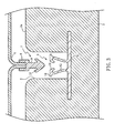
- FIG. 3 is a sectional view of the seat pad 3 taken along line III-III in FIG. 2
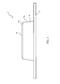
- FIG. 4 is a side view of a clip member 5 to be partly buried in the seat pad 3.
- the vehicle seat S includes a cushion pad 1 for an occupant to sit on and a back pad 2 to support the back of the occupant.
- the cushion pad 1 includes the seat pad 3 (see FIG. 3 ) formed of a foamed synthetic resin such as polyurethane foam, a seat cover 4 to cover a mounting surface 3a on the upper side of the seat pad 3, and the clip members 5 for attaching the seat cover 4 to the seat pad 3.
- the back pad 2 is structured almost identically to the cushion pad 1.
- a groove portion 6 is formed on the mounting surface 3a of the seat pad 3.
- the groove portion 6 includes two front-to-back grooves 6a extending in a front-to-back direction along right and left side portions of the seat pad 3 and two lateral grooves 6b extending from left to right.
- the lateral grooves 6b are each communicated, at both ends thereof, with the front-to-back grooves 6a.
- the front-to-back grooves 6a and lateral grooves 6b are both attached with clip members 5 spaced apart by a predetermined distance along the front-to-back grooves 6a and lateral grooves 6b (in the groove portion 6), respectively.
- the groove portion 6 is not limited to the above arrangement.
- the groove portion 6 formed on the mounting surface 3a of the seat pad 3 has a predetermined depth.
- the groove portion 6 is for partly accommodating the seat cover 4.
- the seat cover 4 has a locking part 7 attached to the reverse side thereof along portions thereof corresponding to the groove portion 6.
- the locking part 7 is for keeping such portions of the seat cover 4 tucked in the groove portion 6.
- the locking part 7 includes a connection part 8 connected to the seat cover 4 by sewing or bonding and a hook part 9 extending from the connection part 8 on the reverse side of the seat cover 4.
- the hook part 9 has, in an end portion thereof, a pair of mutually oppositely extending catching parts 10.
- the catching parts 10 are tapered such that the end portion of each of the catching parts 10 is further away from the hook part 9 toward the base portion of the hook part 9.
- the locking part 7 continuously extends in directions approximately in parallel with the directions in which the groove portion 6 extends. That is, the base portion of the hook part 9 is formed like a hanging wall extending approximately in parallel with the directions in which the groove portion 6 extends.
- the catching parts 10 are each formed to be continuous along the edge portion on each side of the hanging wall.
- the clip members 5 are each for holding a portion of the seat cover 4, in a state of being hung, tucked in the groove portion 6 by locking the locking part 7.
- Each clip member 5 includes a buried part 11 to be buried in the seat pad 3, a pair of extending parts 12 projecting from the buried part 11 and extending in the groove portion 6, a pair of claw-like parts 13 projecting, toward each other, from the end portions of the pair of extending parts 12, respectively, and a pair of guide parts 14 projecting, away from each other, from the end portions of the pair of extending parts 12.
- Each clip member 5 having the above parts is integrally formed of elastic synthetic resin or elastic metal.
- the buried portion 11 is for fixing the clip member 5 in the groove portion 6 of the seat pad 3. It is formed like an approximately flat plate and includes plural through-holes (not shown) formed through the thickness thereof. With the buried part 11 having the through-holes (not shown), the foamed synthetic resin forming the seat pad 3 enters the through-holes thereby generating an anchoring effect to keep the buried part 11 solidly held in the seat pad 3.
- the extending parts 12 are a pair of thin-plate like parts projecting from the surface on one side of the buried part 11, are opposed to each other across a predetermined gap and are formed curvedly to be further away from each other in the direction from their base portion toward their end portions.
- the extending parts 12 each formed like a thin plate can be elastically deformed toward each other or away from each other.
- the claw-like parts 13 are for locking the catching parts 10 of the locking part 7 attached to the reverse side of the seat cover 4 and are formed to extend along the longitudinal direction (the direction vertical to the plane of FIG. 3 ) of the extending parts 12.
- the upper side of each claw-like part 13 (the upper side as seen in FIG. 3 ) is downwardly inclined to be lower (to be closer to the bottom of the groove portion 6) toward the end portion thereof.
- the lower side of each claw-like part 13 (the side on the buried part 11 side) is upwardly inclined to be higher (to be further away from the buried part 11) toward the base portion of the claw-like part 13 (toward the corresponding extending part 12).
- the guide parts 14 are for guiding the catching parts 10 of the locking part 7 for insertion between the claw-like parts 13 and extend in the longitudinal direction (the direction vertical to FIG. 3 ) of the extending parts 12.
- the guide parts 14 are formed to project from the end portions of the mutually opposing extending parts 12 in the directions away from each other.
- Each of the guide parts 14 is formed such that its upper side (its upper surface as seen in FIG. 3 ) is approximately horizontal and such that its underside (its surface on the buried part 11 side) is upwardly inclined to be higher (to be further away from the buried part 11) in the direction from its base portion (its portion on the corresponding extending part 12 side) toward its end portion.
- each extending part 12 and each guide part 14 of each clip member 5 have side edges 12a and 14a, respectively, which are taperedly inclined such that the lengths in the longitudinal direction (in the lateral direction in FIG. 4 ) of the extending part 12 and guide part 14 are smaller in the direction away from the buried part 11.
- the projection (length of projection) from the extending part 12 of each guide part 14 is smaller than the projection (length of projection) from the extending part 12 of each claw-like part 13.
- FIG. 5 is a plan view of the molding die 20 for foam-molding the seat pad 3 according to a first embodiment of the present invention. Note that a lower die included in the molding die 20 is shown in FIG. 5 . The lower die is used to form the mounting surface 3a of the seat pad 3. The upper die used to form a cavity between the lower die and the upper die is not shown.
- the molding die 20 includes a die bottom part 21 having an inner surface used to form the mounting surface 3a of the seat pad 3, a die wall part 22 erected along the outer peripheral edge of the die bottom part 21, and a ridge-like projecting part 23 formed to project like ridges in a predetermined location on the die bottom part 21.
- the ridge-like projecting part 23 is for forming the groove portion 6 of the seat pad 3 and includes recessed accommodation parts 23a for accommodating clip fixing jigs 30 at plural locations spaced apart by a predetermined distance.
- the clip fixing jigs 30 accommodated in the accommodation parts 23a are fixed to the die bottom part 21, for example, using screws.
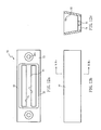
- FIG. 6a is a plan view of a clip fixing jig 30
- FIG. 6b is a side view of the clip fixing jig 30
- FIG. 7a is a sectional view of the clip fixing jig taken along line VIIa-VIIa in FIG. 6a
- FIG. 7b is a sectional view of the clip fixing jig 30 taken along line VIIb-VIIb in FIG. 6b .
- the clip fixing jig 30 is approximately rectangularly formed to be horizontally long in a side view.
- the clip fixing jig 30 is integrally formed of a ferrous material.
- the clip fixing jig 30 has a bottom part 31, and wall parts 32 and 33 erected along a whole outer peripheral edge of the bottom part 31. Catching openings 34 are formed through portions on the bottom part 31 side of the wall parts 32 and 33.
- the bottom part 31 is for connecting the wall parts 32 and 33 to, thereby, secure the mechanical strength of the clip fixing jig 30 and is formed like a rectangular plate in a plan view.
- the wall parts 32 are erected along a pair of long-side outer edges of the bottom part 31.
- Inner wall surfaces 32a (see FIG. 7b ) of the mutually opposing wall parts 32 are inclined such that the distance between them is smaller in the direction from the top ends of the wall parts 32 toward the bottom part 31.
- the wall parts 33 are erected along a pair of short-side outer edges of the bottom part 31. Inner wall surfaces 33a (see FIG. 7a ) of the mutually opposing wall parts 33 are inclined such that the distance between them is smaller in the direction from the top ends of the wall parts 33 toward the bottom part 31.
- the wall parts 33 are formed to be thicker than the wall parts 32.
- Each of the wall parts 33 has a through-hole 33b formed through the height thereof (in the direction vertical to the plane of FIG. 6a ).
- the through-hole 33b has a female-threaded inner surface.
- the catching openings 34 are elongated openings formed in portions on the bottom part 31 side of the wall parts 32 and 33. They are each formed through the thickness of the wall part 32 (in the upper-lower direction in FIG. 6a ) on the corresponding side to be open along the longitudinal direction of the wall part 32 (in the lateral direction in FIG. 6a ) on the corresponding side, and they partly cut into, on both sides in the width direction of the inner wall surface 33a of the wall part 33 on each side, the wall part 33 on each side in the thickness direction thereof (in the lateral direction in FIG. 6a ).
- FIG. 7b the upper boundary of each catching opening 34 formed through the wall part 32 on the corresponding side, i.e.
- each catching opening 34 is larger than the length (the lateral dimension in FIG. 4 ) of each guide part 14 (see FIG. 4 ).
- Each recessed part 35 is a recessed portion formed on an outer surface portion on the bottom part 31 side of each wall part 32.
- the recessed parts 35 each have a horizontally long, rectangular form in a side view.
- the upper boundary of each recessed part 35 is flush with the upper boundary of the corresponding catching opening 34.
- Right and left end portions of each recessed part 35 are outside both end portions of the corresponding catching opening 34.
- FIG. 8 is a sectional view of a clip fixing jig 30 and a clip member 5 fixed to each other.
- the sectional view shown in FIG. 8 is one taken along a direction perpendicular to the longitudinal direction of the ridge-like projecting part 23 of the molding die 20 (see FIG. 5 ).
- the clip fixing jig 30 is accommodated, with the bottom part 31 thereof down, in an accommodation part 23a recessedly formed in the ridge-like projecting part 23.
- the outer side surfaces toward the upper ends of the respective wall parts 32 of the clip fixing jig 30 accommodated in the accommodation part 23a are formed to approximately fit the inner side surfaces of the ridge-like projecting part 23. This prevents the ridge-like projecting part 23 from forming a large undercut relative to the wall part 32 on each side, so that demoldability of the foam-molded seat pad 3 is secured.
- the clip fixing jig 30 is formed such that the distance between the mutually opposing inner wall surfaces 32a is, at the upper ends of the wall parts 32, larger than the distance (the lateral dimension in FIG. 8 ) between the end portions of the guide parts 14. Therefore, when the extending parts 12 of the clip member 5 are entered in the space surrounded by the wall parts 32 and 33, the inner wall surfaces 32a on the upper end sides of the wall parts 32 can be kept from contacting the guide parts 14. Also, the distance between the mutually opposing inner wall surfaces 33a (see FIG. 7a ) is, on the upper end sides of the wall parts 33, smaller than the length (the lateral dimension in FIG. 4 ) of each extending part 12 at the end portion thereof.
- the distance between the inner wall surfaces 32a is, on the bottom part 31 side, smaller than the distance (the lateral dimension in FIG. 8 ) between the end portions of the guide parts 14.
- the extending parts 12 are elastically deformable toward each other or away from each other. Therefore, as the guide parts 14 come closer to the bottom part 31, the end portions of the guide parts 14 start being pressed by the inner wall surfaces 32a to cause the extending parts 12 to be elastically deformed toward each other. This restricts movement, in the direction (in the lateral direction in FIG. 8 ) in which the inner wall surfaces 32a oppose each other, of the extending parts 12 of the clip member 5, so that the clip member 5 can be set in position between the wall parts 32 (in the width direction of the ridge-like projecting part 23 (see FIG. 5 )).
- the distance between the inner wall surfaces 33a is, on the bottom part 31 side of the wall parts 33, approximately the same as the length of the extending parts 12 and guide parts 14 on their end portion sides. This restricts movement, in the direction (in the direction vertical to the plane of FIG. 8 ) in which the inner wall surfaces 33a oppose each other, of the extending parts 12 of the clip member 5, so that the clip member 5 can be set in position between the wall parts 33 (in the longitudinal direction of the ridge-like projecting part 23 (see FIG. 5 )).
- the clip member 5 can be set in position relative to the clip fixing jig 30 both in the horizontal direction and the height direction. With large clearances secured between the wall parts 32 and 33 and the extending parts 12, the extending parts 12 of the clip member 5 can be very easily inserted into the accommodation space SP of the clip fixing jig 30. Thus, workability in fixing the clip member 5 is improved.
- the seat pad 3 (see FIG. 3 ) is foam-molded. Since the clip member 5 is set in position in both the horizontal direction and the vertical direction relative to the clip fixing jig 30, the clip member 5 is prevented from moving when the synthetic resin to form the seat pad 3 is foamed. This allows a portion (the buried part 11) of the clip member 5 to be buried in a predetermined position.
- the clip member 5 When the foam-molded seat pad 3 is detached from the molding die 20, the clip member 5 is moved upward (upward in FIG. 8 ) relative to the clip fixing jig 30. This causes the guide parts 14 caught in the catching openings 34 to turn about the end portions of the extending parts 12 while being pressed by the upper boundary faces of the catching openings 34 and being elastically deformed. As a result, the guide parts 14 leave the catching openings 34 allowing the clip fixing jig 30 and the clip member 5 to be detached from each other.
- the upper boundaries of the catching openings 34 formed through the wall parts 32, i.e. from the inner wall surfaces 32a through the outer wall surfaces, respectively, are inclined to be higher in the direction from the outer surfaces of the wall parts 32 toward the inner wall surfaces 32a. Therefore, the guide parts 14 caught in the catching openings 34 can be moved out of the catching openings with a relatively small force. This prevents the seat pad 3 from being broken at its portion where the clip member 5 is buried.
- the projection (length of projection) from the extending part 12 of each guide part 14 is smaller than the projection (length of projection) from the extending part 12 of the corresponding claw-like part 13. This makes it possible to release the guide parts 14 from the catching openings 34 by making the guide parts 14 turn about the end portions of the extending parts 12, respectively, without requiring the guide parts 14 to turn so much as required in cases where the projections of the guide parts 14 are larger than the projections of the claw-like parts 13. In this way, when detaching the foam-molded seat pad 3 from the molding die 20, the guide parts 14 can be released from the catching openings 34 with ease.
- a second embodiment of the present invention will be described. It has been described for the first embodiment that, in order to fix each clip member 5 including guide parts 14 projecting from the end portions of the extending parts 12 in the directions away from each other, catching openings 34 are formed through the wall parts 32 of the clip fixing jig 30.
- a clip fixing jig 50 for fixing a clip member 40 having no guide parts 14 will be described.
- the parts of the second embodiment identical to those described in connection with the first embodiment will be denoted by reference numerals identical to those used in the first embodiment and description of such parts will be omitted in the following.
- FIG. 9 is a sectional view of a clip member 40 to be fixed to a clip fixing jig 50 according to the second embodiment
- FIG. 10a is a plan view of the clip fixing jig 50
- FIG. 10b is a side view of the clip fixing jig 50
- FIG. 10c is a sectional view of the clip fixing jig 50 taken along line Xc-Xc in FIG. 10b
- the clip member 40 is structured identically to the clip member 5 described in connection with the first embodiment except that the guide parts 14 (see FIG. 3 ) are not included in the clip member 40.
- the clip fixing jig 50 is approximately rectangularly formed to be horizontally long in a side view and includes a bottom part 31, wall parts 32 and 33 erected along a whole outer peripheral edge of the bottom part 31 and an erect part 51 erected on the bottom part 31.
- the erect part 51 is a part erected on a central portion of the bottom part 31 to be spaced apart from the wall parts 32 and 33 by predetermined distances and to extend in parallel with the wall parts 32 and has a tapered shape such that its thickness in the direction in which it opposes the wall parts 32 is smaller toward the end portion thereof.
- the erect part 51 has, on both sides thereof opposing the wall parts 32, catching depressed parts 52 for catching claw-like parts 13.
- the catching depressed parts 52 are formed on both sides of the erect part 51 to be depressed approximately at a center in the height direction of the erect part 51.
- FIG. 11 is a sectional view of the clip fixing jig 50 and the clip member 40 fixed to each other.
- the molding die to which the clip fixing jig 50 is fixed is not shown.
- the extending parts 12 of the clip member 40 are inserted into the accommodation space SP of the clip fixing jig 50.
- the erect part 51 is inserted between the claw-like parts 13.
- the claw-like parts 13 reach where the catching depressed parts 52 are formed, the claw-like parts 13 are caught by the catching depressed parts 52 thanks to elastic deformation of the extending parts 12.
- the upper end faces along the whole upper-end length of the wall parts 32 and 33 come into contact with the buried part 11 of the clip member 40.
- movement of the clip member 40 in the height direction of the clip fixing jig 50 (upper-lower direction in FIG. 11 ) is restricted.
- the clip member 40 can be set in position relative to the clip fixing jig 50 in both the horizontal direction and the height direction. Since large clearances are formed between the wall parts 32 and 33 and the extending parts 12, the extending parts 12 of the clip member 40 can be very easily inserted into the accommodation space SP of the clip fixing jig 50. This improves workability in fixing the clip member 40.
- a third embodiment of the present invention will be described. It has been described for the second embodiment that the erect part 51 having the catching depressed parts 52 is erected on the bottom part 31.
- a clip fixing jig 70 having catching openings 71 formed through the bottom part 31 will be described.
- the parts of the third embodiment identical to those described in connection with the first embodiment will be denoted by reference numerals identical to those used in the first embodiment and description of such parts will be omitted in the following.
- FIG. 12a is a plan view of a clip fixing jig 70
- FIG. 12b is a side view of the clip fixing jig 70
- FIG. 12c is a sectional view of the clip fixing jig 70 taken along line XIIc-XIIc in FIG. 12b
- FIG. 13 is a sectional view of a clip fixing jig 70 and a clip member 60 fixed to each other.
- the molding die to which the clip fixing jig 70 is fixed is not shown in FIG. 13 .
- the clip member 60 is structured identically to the clip member 40 described in connection with the second embodiment except that extending parts 61 are formed to be a little longer.
- the clip fixing jig 70 is approximately rectangularly formed to be horizontally long in a side view and includes a bottom part 31, wall parts 32 and 33 erected along a whole outer peripheral edge of the bottom part 31 and the catching openings 71 formed through the bottom part 31 to catch the claw-like parts 13.
- the catching openings 71 are elongated openings formed through, in the thicknesses direction (in the direction vertical to the plane of FIG. 12a ), two portions of the bottom part 31 to be parallel to each other and to longitudinally (in the lateral direction in FIG. 12a ) extend along the wall parts 32.
- an inner surface 71a on the center side, in the direction in which the wall parts 32 oppose each other is inclined into an undercut state such that the inner surface 71a projects more outwardly, in the direction in which the wall parts 32 oppose each other, in upper portions thereof than in lower portions thereof in the thickness direction of the bottom part 31.
- upper edges 71b on the upper side in the thickness direction of the bottom part 31 of the inner surfaces 71a are positioned such that, when the end portions of the extending parts 61 and the claw-like parts 13 of the clip member 60 are inserted into the catching openings 71, respectively, the upper edges 71b interfere with the claw-like parts 13.
- the extending parts 61 of the clip member 60 are inserted into the accommodation space SP of the clip fixing jig 70.
- the extending parts 61 of the clip member 60 are inserted in the accommodation space SP and the claw-like parts 13 reach the upper edges 71b of the catching openings 71, the extending parts 61 are elastically deformed away from each other, thereby allowing the claw-like parts 13 to be inserted into the catching openings 71.
- the clip member 60 can be set in position relative to the clip fixing jig 70 in both the horizontal direction and the height direction. Since large clearances are formed between the wall parts 32 and 33 and the extending parts 61, the extending parts 61 of the clip member 60 can be very easily inserted into the accommodation space SP of the clip fixing jig 70. This improves workability in fixing the clip member 60.
- a fourth embodiment of the present invention will be described. It has been described for the first to third embodiments that, by having the claw-like parts 13 and guide parts 14 included in the clip members 5, 40 or 60 caught by the catching openings 34 or 71 or catching depressed parts 52 included in the clip fixing jigs 30, 50 or 70, the clip members 5, 40 and 60 are fixed to the clip fixing jigs 30, 50 and 70, respectively.
- using a magnetic force (attraction force) to attract (fix) a clip member 80 to a clip fixing jig 90 will be described.
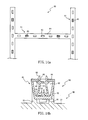
- FIG. 14a is a plan view of a clip member 80 according to the fourth embodiment
- FIG. 14b is a sectional view of a clip fixing jig 90 and the clip member 80 fixed to each other.
- the clip member 80 includes plural clips 81 and a connection member 84 connecting the plural clips 81 at their base parts.
- the connection member 84 is formed of a belt-like magnetic material (ferrous material in the present embodiment) to be identical, in a plan view, to the ridge-like projecting part 23 (see FIG. 5 ) of the molding die 20 and has lined-up through-holes 85 formed therethrough in the thickness direction (the direction vertical to the plane of FIG. 14a ).
- the connection member 84 has a width which allows the upper-end faces of a pair of wall parts 32 of the clip fixing jig 90 to come into contact with the connection member 84.
- the through-holes 85 are for fixing the clips 81 to predetermined locations of the connection member 84. Also, when the connection member 84 is buried in the seat pad 3 (see FIG. 3 ), it generates an anchoring effect with the foamed molding material having entered thereinside.
- the clip member 80 holds the clips 81 correspondingly to the clip fixing jigs 90 placed in the molding die 20.
- each clip 81 includes a plate-like flange part 82 to be in contact with one side of the connection member 84, a pair of extending parts 12 projectingly extending form the flange part 82, a pair of claw-like parts 13 formed to project, toward each other, from the end portions of the extending parts 12, respectively, and a pair of guide parts 14 formed to extend, away from each other, from the end portions of the extending parts 12, respectively.
- These parts are integrally formed of elastic synthetic resin or elastic metal.
- the flange part 82 is put in contact with one side of the connection member 84 and has an outer diameter (shape) which cannot pass through the through-hole 85.
- the flange part 82 is provided with a pair of catching parts 83 projecting from the side thereof opposite to the side from which the extending parts 12 project.
- the catching parts 83 are thin plate-like parts projecting from the flange part 82 to be spaced apart from each other by a predetermined distance and are elastically deformable away from each other and toward each other.
- the catching parts 83 are inserted through the through-hole 85 formed through the connection member 84, have claw-like parts which are put in contact with the opposite side of the connection part 84 and which project in the directions away from each other.
- the flange part 82 and the catching parts 83 are positioned on the two sides of the connection member 84, respectively, making the clip 81 inseparable from the connection part 84 (through-hole 85).
- the clip fixing jig 90 is structured identically to the clip fixing jig 20 described in connection with the first embodiment except that the wall parts 32 do not include the catching openings 34 (see FIG. 8 ).
- the clip fixing jig 90 is integrally formed of a magnetic material (ferrous material in the present embodiment) and is placed in the molding die 20 with a permanent magnet 91 magnetically attached to the underside of the bottom part 31. This magnetizes the magnetic clip fixing jig 90 placed in the molding die 20.
- the extending parts 12 of the clip member 80 are inserted in the accommodation space SP of the clip fixing jig 90.
- the clip fixing jig 90 formed of a magnetic material magnetized by the permanent magnet 91
- the magnetized wall parts 32 detachably attract the connection member 84 formed of a magnetic material.
- the clip member 80 with the plural clips 81 arranged thereon can be magnetically attached (fixed) altogether to the clip fixing jigs 90 without requiring the clips 81 to be fixed to the clip fixing jigs 90 one by one. This greatly improves workability in fixing the clip members 80.
- the molding die 20 and clip fixing jigs 30, 50, 70 and 90 used to form the seat pad 3 for the cushion pad 1 have been described, application of the present invention is not necessarily limited to such parts. It is obviously possible to apply the present invention to a molding die and clip fixing jigs used to form a seat pad for the back pad 2.
- the clip fixing jigs 30, 50, 70 and 90 need not necessarily be so. It is obviously possible to form the clip fixing jigs 30, 50, 70, and 90 integrally with the molding die 20.
- the bottom part 31 of the clip fixing jig 30 need not necessarily be so.
- the bottom part 31 is intended to secure the mechanical strength of the clip fixing jig 30 by being connected with the wall parts 32 and 33.
- the mechanical strength of the clip fixing jig 30 is allowed to be slightly lower, it is obviously possible that the bottom part 31 has an annular form.
- the bottom part 31 is annular, it is provided at the lower ends of the wall parts 32 and 33. In this case, it is possible to have the guide parts 14 caught at the underside of the bottom part provided at the lower ends of the wall parts 32.
- the catching openings 34 through the wall parts 32 and have the guide parts 14 caught in the catching openings 34.
Abstract
Description
- The present invention relates to a clip fixing jig and a seat pad molding die provided with the same and, more particularly, to a clip fixing jig which can improve workability in clip member fixing work and to a seat pad molding die provided with the clip fixing jig.
- There has been a technique in which a portion of a seat cover is, in a state of being hung, put and held in a groove portion formed on the surface of a seat pad, thereby attaching the seat cover, in a state with wrinkles formed in excess portions thereof stretched out, to the seat pad. For example,
Patent Literature 1 discloses a technique in which: a linear part, e.g. a wire, is provided in a groove portion of a seat pad; base parts of plural clip members are fixed to plural portions of the linear part; and extending parts having claw-like parts in their end portions are positioned to be extending inside the groove portion. According to the technique, a locking part provided on the reverse side of the seat cover is held by the claw-like parts (clip members) provided at plural locations in the groove portion, allowing a portion of the seat cover to be held, in a state of being hung, in the groove portion. - [Patent Literature 1]
JP-A No. 2011-45424 - The existing technique described above, however, poses a problem that fixing plural clip members to plural portions of a linear part is cumbersome work involving a large number of work steps.
- The present invention has been made to address the above problem, and it is an object of the present invention to provide a clip fixing jig and a seat pad molding die provided with the same that can improve workability in clip member fixing work.
- The clip fixing jig according to
claim 1 is for fixing a clip member to be partly buried in a seat pad, which has a groove portion for accommodating a portion of a seat cover, in a molding die for molding a seat pad. The clip member has a buried part to be buried in the seat pad and an extending part extending from the buried part into the groove portion. A claw-like part is formed to extend from an end portion of the extending part. The claw-like part catches and holds a catching part provided on the reverse side of the seat pad. - The clip fixing jig for fixing the clip member in the seat pad molding die has a plate-like or annular bottom part with a wall part erected along a whole outer peripheral edge thereof. The wall part forms, above the bottom part, an accommodation space for accommodating the extending part. A fixing part is formed at a predetermined part provided in the accommodation space or formed in the bottom part or in the wall part, and a predetermined part of the clip member is detachably fixed to the fixing part. In this arrangement, the clip member can be fixed to the clip fixing jig by inserting the extending part of the clip member into the accommodation space surrounded by the wall part. With the clip fixing jig provided in a molding die, a seat pad can be formed by insert molding. This generates an effect of improving workability in clip member fixing work.
- In the clip fixing jig according to
claim 2, mutually opposing inner surfaces of the wall part are inclined such that a distance between the mutually opposing inner surfaces is smaller in a direction from an upper end of the wall part toward the bottom part. This makes it easy to insert the extending part of the clip member between the inner wall surfaces. Hence, in addition to the effect generated according toclaim 1, workability in clip member fixing work is further improved. - Also, the wall part is formed to restrict movement of the extending part of the clip member in the direction in which the inner wall surfaces oppose each other. This generates an effect of preventing the clip member from being shifted in the direction in which the inner wall surfaces oppose each other.
- In the clip fixing jig according to
claim 3, when the extending part of the clip member is accommodated in the accommodation space, the upper end face along a whole upper-end length of the wall part comes into contact with the buried part. This prevents, when the seat pad is foam-molded, the foamed molding material from partly entering the accommodation space of the clip fixing jig. If part of the foamed molding material enters the accommodation space of the clip fixing jig and adheres to the extending part or claw-like part, it may become difficult to have a locking part provided on the reverse side of the seat cover caught by the claw-like part (to attach the seat cover to the seat pad). Since such difficulty is prevented, an effect of securing workability in attaching the seat cover to the seat pad is generated in addition to the effects generated according toclaims - The molding die for molding a seat pad according to claim 4 includes clip fixing jigs, each being according to one of
claims 1 to 3, arranged therein. The clip member includes plural clips which are each provided with the extending part and the claw-like part and a connection member which is formed of a magnetic material and connects the clips. The clip fixing jigs are formed of a magnetic material and are magnetized by a magnet. The wall parts of the magnetized clip fixing jigs detachably attract the connection member. With the plural clips connected by the connection member and with the clip fixing jigs located correspondingly to the locations of the clips, the clip member can be fixed altogether to the clip fixing jigs without requiring the clips to be fixed to the clip fixing jigs one by one. Therefore, in addition to the effect generated according to one ofclaims 1 to 3, workability in clip member fixing work is greatly improved. -
- [
FIG. 1] FIG. 1 is a perspective view of a vehicle seat. - [
FIG. 2] FIG. 2 is a plan view of a seat pad attached with clip members. - [
FIG. 3] FIG. 3 is a sectional view of the seat pad taken along line III-III inFIG. 2 . - [
FIG. 4] FIG. 4 is a side view of a clip member to be partly buried in the seat pad. - [
FIG. 5] FIG. 5 is a plan view of a seat pad molding die according to a first embodiment of the present invention. - [
FIG. 6] FIG. 6a is a plan view of a clip fixing jig; andFIG. 6b is a side view of the clip fixing jig. - [
FIG. 7] FIG. 7a is a sectional view of the clip fixing jig taken along line VIIa-VIIa inFIG. 6a ; andFIG. 7b is a sectional view of the clip fixing jig taken along line VIIb-VIIb inFIG. 6b . - [
FIG. 8] FIG. 8 is a sectional view of the clip fixing jig and the clip member fixed to each other. - [
FIG. 9] FIG. 9 is a sectional view of a clip member to be fixed to a clip fixing jig according to a second embodiment. - [
FIG. 10] FIG. 10a is a plan view of a clip fixing jig;FIG. 10b is a side view of the clip fixing jig; andFIG. 10c is a sectional view of the clip fixing jig taken along line Xc-Xc inFIG. 10b . - [
FIG. 11] FIG. 11 is a sectional view of the clip fixing jig and the clip member fixed to each other. - [
FIG. 12] FIG. 12a is a plan view of a clip fixing jig according to a third embodiment;FIG. 12b is a side view of the clip fixing jig; andFIG. 12c is a sectional view of the clip fixing jig taken along line XIIc-XIIc inFIG. 12b . - [
FIG. 13] FIG. 13 is a sectional view of the clip fixing jig and the clip member fixed to each other. - [
FIG. 14] FIG. 14a is a plan view of a clip member according to a fourth embodiment; andFIG. 14b is a sectional view of a clip fixing jig and the clip member fixed to each other. - In the following, preferred embodiments of the present invention will be described with reference to the attached drawings.
FIG. 1 is a perspective view of a vehicle seat S;FIG. 2 is a plan view of aseat pad 3 attached withclip members 5;FIG. 3 is a sectional view of theseat pad 3 taken along line III-III inFIG. 2 ; andFIG. 4 is a side view of aclip member 5 to be partly buried in theseat pad 3. - As shown in
FIG. 1 , the vehicle seat S includes acushion pad 1 for an occupant to sit on and aback pad 2 to support the back of the occupant. Thecushion pad 1 includes the seat pad 3 (seeFIG. 3 ) formed of a foamed synthetic resin such as polyurethane foam, a seat cover 4 to cover a mountingsurface 3a on the upper side of theseat pad 3, and theclip members 5 for attaching the seat cover 4 to theseat pad 3. Though not shown, theback pad 2 is structured almost identically to thecushion pad 1. - As shown in
FIG. 2 , agroove portion 6 is formed on the mountingsurface 3a of theseat pad 3. In the present embodiment, thegroove portion 6 includes two front-to-back grooves 6a extending in a front-to-back direction along right and left side portions of theseat pad 3 and twolateral grooves 6b extending from left to right. Thelateral grooves 6b are each communicated, at both ends thereof, with the front-to-back grooves 6a. The front-to-back grooves 6a andlateral grooves 6b are both attached withclip members 5 spaced apart by a predetermined distance along the front-to-back grooves 6a andlateral grooves 6b (in the groove portion 6), respectively. Note that thegroove portion 6 is not limited to the above arrangement. - As shown in
FIG. 3 , thegroove portion 6 formed on the mountingsurface 3a of theseat pad 3 has a predetermined depth. Thegroove portion 6 is for partly accommodating the seat cover 4. The seat cover 4 has a lockingpart 7 attached to the reverse side thereof along portions thereof corresponding to thegroove portion 6. The lockingpart 7 is for keeping such portions of the seat cover 4 tucked in thegroove portion 6. The lockingpart 7 includes aconnection part 8 connected to the seat cover 4 by sewing or bonding and a hook part 9 extending from theconnection part 8 on the reverse side of the seat cover 4. The hook part 9 has, in an end portion thereof, a pair of mutually oppositely extending catchingparts 10. The catchingparts 10 are tapered such that the end portion of each of the catchingparts 10 is further away from the hook part 9 toward the base portion of the hook part 9. - The locking
part 7 continuously extends in directions approximately in parallel with the directions in which thegroove portion 6 extends. That is, the base portion of the hook part 9 is formed like a hanging wall extending approximately in parallel with the directions in which thegroove portion 6 extends. The catchingparts 10 are each formed to be continuous along the edge portion on each side of the hanging wall. - The
clip members 5 are each for holding a portion of the seat cover 4, in a state of being hung, tucked in thegroove portion 6 by locking the lockingpart 7. Eachclip member 5 includes a buriedpart 11 to be buried in theseat pad 3, a pair of extendingparts 12 projecting from the buriedpart 11 and extending in thegroove portion 6, a pair of claw-like parts 13 projecting, toward each other, from the end portions of the pair of extendingparts 12, respectively, and a pair ofguide parts 14 projecting, away from each other, from the end portions of the pair of extendingparts 12. Eachclip member 5 having the above parts is integrally formed of elastic synthetic resin or elastic metal. - The buried
portion 11 is for fixing theclip member 5 in thegroove portion 6 of theseat pad 3. It is formed like an approximately flat plate and includes plural through-holes (not shown) formed through the thickness thereof. With the buriedpart 11 having the through-holes (not shown), the foamed synthetic resin forming theseat pad 3 enters the through-holes thereby generating an anchoring effect to keep the buriedpart 11 solidly held in theseat pad 3. - The extending
parts 12 are a pair of thin-plate like parts projecting from the surface on one side of the buriedpart 11, are opposed to each other across a predetermined gap and are formed curvedly to be further away from each other in the direction from their base portion toward their end portions. The extendingparts 12 each formed like a thin plate can be elastically deformed toward each other or away from each other. - The claw-
like parts 13 are for locking the catchingparts 10 of the lockingpart 7 attached to the reverse side of the seat cover 4 and are formed to extend along the longitudinal direction (the direction vertical to the plane ofFIG. 3 ) of the extendingparts 12. The upper side of each claw-like part 13 (the upper side as seen inFIG. 3 ) is downwardly inclined to be lower (to be closer to the bottom of the groove portion 6) toward the end portion thereof. The lower side of each claw-like part 13 (the side on the buriedpart 11 side) is upwardly inclined to be higher (to be further away from the buried part 11) toward the base portion of the claw-like part 13 (toward the corresponding extending part 12). - The
guide parts 14 are for guiding the catchingparts 10 of the lockingpart 7 for insertion between the claw-like parts 13 and extend in the longitudinal direction (the direction vertical toFIG. 3 ) of the extendingparts 12. Theguide parts 14 are formed to project from the end portions of the mutually opposing extendingparts 12 in the directions away from each other. With theguide parts 14 provided, when inserting the lockingpart 7 in theclip member 5, the hook part 9 is prevented from entering between the extendingpart 12 on either side and the inner wall on the corresponding side of thegroove portion 6, so that failure to achieve smooth engagement between the catchingpart 10 and the claw-like part 13 is prevented. - Each of the
guide parts 14 is formed such that its upper side (its upper surface as seen inFIG. 3 ) is approximately horizontal and such that its underside (its surface on the buriedpart 11 side) is upwardly inclined to be higher (to be further away from the buried part 11) in the direction from its base portion (its portion on the corresponding extendingpart 12 side) toward its end portion. As shown inFIG. 4 , each extendingpart 12 and each guidepart 14 of eachclip member 5 haveside edges FIG. 4 ) of the extendingpart 12 and guidepart 14 are smaller in the direction away from the buriedpart 11. Also, the projection (length of projection) from the extendingpart 12 of eachguide part 14 is smaller than the projection (length of projection) from the extendingpart 12 of each claw-like part 13. - Next, with reference to
FIG. 5 , amolding die 20 for foam-molding theseat pad 3 will be described.FIG. 5 is a plan view of the molding die 20 for foam-molding theseat pad 3 according to a first embodiment of the present invention. Note that a lower die included in the molding die 20 is shown inFIG. 5 . The lower die is used to form the mountingsurface 3a of theseat pad 3. The upper die used to form a cavity between the lower die and the upper die is not shown. - As shown in
FIG. 5 , the molding die 20 includes adie bottom part 21 having an inner surface used to form the mountingsurface 3a of theseat pad 3, adie wall part 22 erected along the outer peripheral edge of thedie bottom part 21, and a ridge-like projectingpart 23 formed to project like ridges in a predetermined location on thedie bottom part 21. The ridge-like projectingpart 23 is for forming thegroove portion 6 of theseat pad 3 and includes recessedaccommodation parts 23a for accommodatingclip fixing jigs 30 at plural locations spaced apart by a predetermined distance. Theclip fixing jigs 30 accommodated in theaccommodation parts 23a are fixed to the diebottom part 21, for example, using screws. - Next, with reference to
FIGS. 6 to 8 , theclip fixing jigs 30 will be described. First, with reference toFIGS. 6 and7 , the structure of eachclip fixing jig 30 will be described.FIG. 6a is a plan view of aclip fixing jig 30;FIG. 6b is a side view of theclip fixing jig 30;FIG. 7a is a sectional view of the clip fixing jig taken along line VIIa-VIIa inFIG. 6a ; andFIG. 7b is a sectional view of theclip fixing jig 30 taken along line VIIb-VIIb inFIG. 6b . - As shown in
FIGS. 6a and 6b , theclip fixing jig 30 is approximately rectangularly formed to be horizontally long in a side view. In the present embodiment, theclip fixing jig 30 is integrally formed of a ferrous material. As shown inFIG. 6a to FIG. 7b , theclip fixing jig 30 has abottom part 31, andwall parts bottom part 31. Catchingopenings 34 are formed through portions on thebottom part 31 side of thewall parts - The
bottom part 31 is for connecting thewall parts clip fixing jig 30 and is formed like a rectangular plate in a plan view. Thewall parts 32 are erected along a pair of long-side outer edges of thebottom part 31.Inner wall surfaces 32a (seeFIG. 7b ) of the mutually opposingwall parts 32 are inclined such that the distance between them is smaller in the direction from the top ends of thewall parts 32 toward thebottom part 31. When theclip fixing jig 30 is accommodated in anaccommodation part 23a, thewall parts 32 are positioned along the longitudinal direction of the ridge-like projectingpart 23. - The
wall parts 33 are erected along a pair of short-side outer edges of thebottom part 31.Inner wall surfaces 33a (seeFIG. 7a ) of the mutually opposingwall parts 33 are inclined such that the distance between them is smaller in the direction from the top ends of thewall parts 33 toward thebottom part 31. Thewall parts 33 are formed to be thicker than thewall parts 32. Each of thewall parts 33 has a through-hole 33b formed through the height thereof (in the direction vertical to the plane ofFIG. 6a ). The through-hole 33b has a female-threaded inner surface. By clamping a screw (not shown) which is screwed in each through-hole 33b to the diebottom part 21, theclip fixing jig 30 accommodated in anaccommodation part 23a (seeFIG. 5 ) is fixed to the diebottom part 21. An accommodation space SP surrounded by thewall parts bottom part 31. The accommodation space SP is for accommodating the extendingparts 12 of aclip member 5. - The catching
openings 34 are elongated openings formed in portions on thebottom part 31 side of thewall parts FIG. 6a ) on the corresponding side to be open along the longitudinal direction of the wall part 32 (in the lateral direction inFIG. 6a ) on the corresponding side, and they partly cut into, on both sides in the width direction of theinner wall surface 33a of thewall part 33 on each side, thewall part 33 on each side in the thickness direction thereof (in the lateral direction inFIG. 6a ). As shown inFIG. 7b , the upper boundary of each catchingopening 34 formed through thewall part 32 on the corresponding side, i.e. through from theinner wall surface 32a of thewall part 32 to the outer wall surface is inclined to be higher in the direction from the outer wall surface toward theinner wall surface 32a of thewall part 32. The length (the lateral dimension inFIG. 6a ) of each catchingopening 34 is larger than the length (the lateral dimension inFIG. 4 ) of each guide part 14 (seeFIG. 4 ). - Each recessed
part 35 is a recessed portion formed on an outer surface portion on thebottom part 31 side of eachwall part 32. The recessedparts 35 each have a horizontally long, rectangular form in a side view. The upper boundary of each recessedpart 35 is flush with the upper boundary of the corresponding catchingopening 34. Right and left end portions of each recessedpart 35 are outside both end portions of the corresponding catchingopening 34. With the recessedparts 35 formed, eachwall part 32 has a reduced thickness, so that the catchingopenings 34 can be formed through thewall parts 32 with ease. - Next, with reference to
FIG. 8 , aclip fixing jig 30 with aclip member 5 fixed thereto will be described.FIG. 8 is a sectional view of aclip fixing jig 30 and aclip member 5 fixed to each other. The sectional view shown inFIG. 8 is one taken along a direction perpendicular to the longitudinal direction of the ridge-like projectingpart 23 of the molding die 20 (seeFIG. 5 ). Theclip fixing jig 30 is accommodated, with thebottom part 31 thereof down, in anaccommodation part 23a recessedly formed in the ridge-like projectingpart 23. The outer side surfaces toward the upper ends of therespective wall parts 32 of theclip fixing jig 30 accommodated in theaccommodation part 23a are formed to approximately fit the inner side surfaces of the ridge-like projectingpart 23. This prevents the ridge-like projectingpart 23 from forming a large undercut relative to thewall part 32 on each side, so that demoldability of the foam-moldedseat pad 3 is secured. - As shown in
FIG. 8 , theclip fixing jig 30 is formed such that the distance between the mutually opposinginner wall surfaces 32a is, at the upper ends of thewall parts 32, larger than the distance (the lateral dimension inFIG. 8 ) between the end portions of theguide parts 14. Therefore, when the extendingparts 12 of theclip member 5 are entered in the space surrounded by thewall parts wall parts 32 can be kept from contacting theguide parts 14. Also, the distance between the mutually opposinginner wall surfaces 33a (seeFIG. 7a ) is, on the upper end sides of thewall parts 33, smaller than the length (the lateral dimension inFIG. 4 ) of each extendingpart 12 at the end portion thereof. Furthermore, the mutually opposing inner wall surfaces 32a and the mutually opposing inner wall surfaces 33a are inclined such that the distances between the mutually opposing inner wall surfaces 32a and between the mutually opposing inner wall surfaces 33a are smaller in the direction from the top ends of thewall parts bottom part 31. This prevents interference between theclip fixing jig 30 and theclip member 5 and makes it easy to insert the extendingpart 12 of theclip member 5 in the space (accommodation space SP) surrounded by thewall parts - The distance between the
inner wall surfaces 32a is, on thebottom part 31 side, smaller than the distance (the lateral dimension inFIG. 8 ) between the end portions of theguide parts 14. The extendingparts 12 are elastically deformable toward each other or away from each other. Therefore, as theguide parts 14 come closer to thebottom part 31, the end portions of theguide parts 14 start being pressed by the inner wall surfaces 32a to cause the extendingparts 12 to be elastically deformed toward each other. This restricts movement, in the direction (in the lateral direction inFIG. 8 ) in which the inner wall surfaces 32a oppose each other, of the extendingparts 12 of theclip member 5, so that theclip member 5 can be set in position between the wall parts 32 (in the width direction of the ridge-like projecting part 23 (seeFIG. 5 )). - The distance between the
inner wall surfaces 33a (seeFIG. 7a ) is, on thebottom part 31 side of thewall parts 33, approximately the same as the length of the extendingparts 12 and guideparts 14 on their end portion sides. This restricts movement, in the direction (in the direction vertical to the plane ofFIG. 8 ) in which the inner wall surfaces 33a oppose each other, of the extendingparts 12 of theclip member 5, so that theclip member 5 can be set in position between the wall parts 33 (in the longitudinal direction of the ridge-like projecting part 23 (seeFIG. 5 )). - When the
guide parts 14 of theclip member 5 inserted in theclip fixing jig 30 reach the catchingopenings 34 formed through thewall parts 32, the extendingparts 12 elastically deformed toward each other are released to move back away from each other. As a result, theguide parts 14 are inserted into the catchingopenings 34 to be caught there. At this time, the upper end faces along the whole upper-end length of thewall parts part 11 of theclip member 5. As a result, movement of theclip member 5 in the height direction (in the upper-lower direction inFIG. 8 ) of theclip fixing jig 30 is restricted, so that theclip member 5 can be set in position in the height direction of theclip fixing jig 30. - As described above, just by inserting the extending
parts 12 of theclip member 5 in the accommodation space SP of theclip fixing jig 30, theclip member 5 can be set in position relative to theclip fixing jig 30 both in the horizontal direction and the height direction. With large clearances secured between thewall parts parts 12, the extendingparts 12 of theclip member 5 can be very easily inserted into the accommodation space SP of theclip fixing jig 30. Thus, workability in fixing theclip member 5 is improved. - In the above state, the seat pad 3 (see
FIG. 3 ) is foam-molded. Since theclip member 5 is set in position in both the horizontal direction and the vertical direction relative to theclip fixing jig 30, theclip member 5 is prevented from moving when the synthetic resin to form theseat pad 3 is foamed. This allows a portion (the buried part 11) of theclip member 5 to be buried in a predetermined position. - Also, since the upper end faces along the whole upper-end length of the
wall parts part 11 of theclip member 5, when theseat pad 3 is foam-molded, it does not occur that part of the foamed molding material enters the accommodation space SP of theclip fixing jig 30. If part of the foamed molding material enters the accommodation space SP of theclip fixing jig 30 and adheres to the extendingparts 12 or claw-like parts 13, it may become difficult to have the lockingpart 7 provided on the reverse side of the seat cover 4 (seeFIG. 3 ) caught by the claw-like parts 13 (to attach the seat cover 4 to the seat pad 3). Since such difficulty can be prevented, workability in attaching the seat cover 4 to theseat pad 3 can be secured. - When the foam-molded
seat pad 3 is detached from the molding die 20, theclip member 5 is moved upward (upward inFIG. 8 ) relative to theclip fixing jig 30. This causes theguide parts 14 caught in the catchingopenings 34 to turn about the end portions of the extendingparts 12 while being pressed by the upper boundary faces of the catchingopenings 34 and being elastically deformed. As a result, theguide parts 14 leave the catchingopenings 34 allowing theclip fixing jig 30 and theclip member 5 to be detached from each other. - The upper boundaries of the catching
openings 34 formed through thewall parts 32, i.e. from the inner wall surfaces 32a through the outer wall surfaces, respectively, are inclined to be higher in the direction from the outer surfaces of thewall parts 32 toward theinner wall surfaces 32a. Therefore, theguide parts 14 caught in the catchingopenings 34 can be moved out of the catching openings with a relatively small force. This prevents theseat pad 3 from being broken at its portion where theclip member 5 is buried. - Furthermore, the underside surfaces (surfaces on the buried
part 11 side) of theguide parts 14 are inclined to be further away from the buriedpart 11 in the direction from the base portions (on the extendingpart 12 sides) toward the end portions of theguide parts 14, respectively. Therefore, when theclip member 5 is moved upward (upward inFIG. 8 ) relative to theclip fixing jig 30, theguide parts 14 caught in the catchingopenings 34 can be released from the catchingopenings 34 with ease. - Also, the projection (length of projection) from the extending
part 12 of eachguide part 14 is smaller than the projection (length of projection) from the extendingpart 12 of the corresponding claw-like part 13. This makes it possible to release theguide parts 14 from the catchingopenings 34 by making theguide parts 14 turn about the end portions of the extendingparts 12, respectively, without requiring theguide parts 14 to turn so much as required in cases where the projections of theguide parts 14 are larger than the projections of the claw-like parts 13. In this way, when detaching the foam-moldedseat pad 3 from the molding die 20, theguide parts 14 can be released from the catchingopenings 34 with ease. - Next, with reference to
FIGS. 9 to 11 , a second embodiment of the present invention will be described. It has been described for the first embodiment that, in order to fix eachclip member 5 includingguide parts 14 projecting from the end portions of the extendingparts 12 in the directions away from each other, catchingopenings 34 are formed through thewall parts 32 of theclip fixing jig 30. For the second embodiment, aclip fixing jig 50 for fixing aclip member 40 having noguide parts 14 will be described. The parts of the second embodiment identical to those described in connection with the first embodiment will be denoted by reference numerals identical to those used in the first embodiment and description of such parts will be omitted in the following. -
FIG. 9 is a sectional view of aclip member 40 to be fixed to aclip fixing jig 50 according to the second embodiment;FIG. 10a is a plan view of theclip fixing jig 50;FIG. 10b is a side view of theclip fixing jig 50; andFIG. 10c is a sectional view of theclip fixing jig 50 taken along line Xc-Xc inFIG. 10b . As shown inFIG. 9 , theclip member 40 is structured identically to theclip member 5 described in connection with the first embodiment except that the guide parts 14 (seeFIG. 3 ) are not included in theclip member 40. - As shown in
FIGS. 10a to 10c , theclip fixing jig 50 is approximately rectangularly formed to be horizontally long in a side view and includes abottom part 31,wall parts bottom part 31 and anerect part 51 erected on thebottom part 31. Theerect part 51 is a part erected on a central portion of thebottom part 31 to be spaced apart from thewall parts wall parts 32 and has a tapered shape such that its thickness in the direction in which it opposes thewall parts 32 is smaller toward the end portion thereof. Theerect part 51 has, on both sides thereof opposing thewall parts 32, catchingdepressed parts 52 for catching claw-like parts 13. The catchingdepressed parts 52 are formed on both sides of theerect part 51 to be depressed approximately at a center in the height direction of theerect part 51. - Next, with reference to
FIG. 11 , aclip fixing jig 50 with aclip member 40 fixed thereto will be described.FIG. 11 is a sectional view of theclip fixing jig 50 and theclip member 40 fixed to each other. The molding die to which theclip fixing jig 50 is fixed is not shown. - As shown in
FIG. 11 , to fix theclip member 40 to theclip fixing jig 50 attached to the molding die (not shown), the extendingparts 12 of theclip member 40 are inserted into the accommodation space SP of theclip fixing jig 50. When the extendingparts 12 of theclip member 40 are inserted in the accommodation space SP, theerect part 51 is inserted between the claw-like parts 13. When the claw-like parts 13 reach where the catchingdepressed parts 52 are formed, the claw-like parts 13 are caught by the catchingdepressed parts 52 thanks to elastic deformation of the extendingparts 12. At this time, the upper end faces along the whole upper-end length of thewall parts part 11 of theclip member 40. As a result, movement of theclip member 40 in the height direction of the clip fixing jig 50 (upper-lower direction inFIG. 11 ) is restricted. - On the other hand, movement of the
clip member 40 in the direction (the lateral direction inFIG. 11 ) in which thewall parts 32 of theclip fixing jig 50 oppose each other is restricted with theerect part 51 inserted between the elasticallydeformable extending parts 12. Also, movement of theclip member 40 in the direction (the lateral direction inFIG. 10a ) in which thewall parts 33 of theclip fixing jig 50 oppose each other is restricted by the clearances generated by the difference between the distance between thewall parts 33 on thebottom part 31 side and the corresponding dimensions of the extendingparts 12. Thus, theclip member 40 can be set in position in both the horizontal direction and the height direction of theclip fixing member 50. - As described above, just by inserting the extending
parts 12 of theclip member 40 into the accommodation space SP of theclip fixing jig 50, theclip member 40 can be set in position relative to theclip fixing jig 50 in both the horizontal direction and the height direction. Since large clearances are formed between thewall parts parts 12, the extendingparts 12 of theclip member 40 can be very easily inserted into the accommodation space SP of theclip fixing jig 50. This improves workability in fixing theclip member 40. - Next, with reference to
FIGS. 12 and13 , a third embodiment of the present invention will be described. It has been described for the second embodiment that theerect part 51 having the catchingdepressed parts 52 is erected on thebottom part 31. For the third embodiment, aclip fixing jig 70 having catchingopenings 71 formed through thebottom part 31 will be described. The parts of the third embodiment identical to those described in connection with the first embodiment will be denoted by reference numerals identical to those used in the first embodiment and description of such parts will be omitted in the following. -
FIG. 12a is a plan view of aclip fixing jig 70;FIG. 12b is a side view of theclip fixing jig 70;FIG. 12c is a sectional view of theclip fixing jig 70 taken along line XIIc-XIIc inFIG. 12b ; andFIG. 13 is a sectional view of aclip fixing jig 70 and aclip member 60 fixed to each other. The molding die to which theclip fixing jig 70 is fixed is not shown inFIG. 13 . As shown inFIG. 13 , theclip member 60 is structured identically to theclip member 40 described in connection with the second embodiment except that extendingparts 61 are formed to be a little longer. - As shown in
FIGS. 12a to 12c , theclip fixing jig 70 is approximately rectangularly formed to be horizontally long in a side view and includes abottom part 31,wall parts bottom part 31 and the catchingopenings 71 formed through thebottom part 31 to catch the claw-like parts 13. The catchingopenings 71 are elongated openings formed through, in the thicknesses direction (in the direction vertical to the plane ofFIG. 12a ), two portions of thebottom part 31 to be parallel to each other and to longitudinally (in the lateral direction inFIG. 12a ) extend along thewall parts 32. - As shown in
FIG. 12c andFIG. 13 , of the inner surfaces of each catchingopening 71 formed through, in the thickness direction, thebottom part 31, aninner surface 71a on the center side, in the direction in which thewall parts 32 oppose each other, is inclined into an undercut state such that theinner surface 71a projects more outwardly, in the direction in which thewall parts 32 oppose each other, in upper portions thereof than in lower portions thereof in the thickness direction of thebottom part 31. Also,upper edges 71b on the upper side in the thickness direction of thebottom part 31 of theinner surfaces 71a are positioned such that, when the end portions of the extendingparts 61 and the claw-like parts 13 of theclip member 60 are inserted into the catchingopenings 71, respectively, theupper edges 71b interfere with the claw-like parts 13. - As shown in
FIG. 13 , to fix theclip member 60 to theclip fixing jig 70 attached to the molding die (not shown), the extendingparts 61 of theclip member 60 are inserted into the accommodation space SP of theclip fixing jig 70. When the extendingparts 61 of theclip member 60 are inserted in the accommodation space SP and the claw-like parts 13 reach theupper edges 71b of the catchingopenings 71, the extendingparts 61 are elastically deformed away from each other, thereby allowing the claw-like parts 13 to be inserted into the catchingopenings 71. When the claw-like parts 13 are inserted into the catchingopenings 71, the elastically deformed extendingparts 61 are restored into an undeformed state causing the claw-like parts 13 to come into contact with theinner surfaces 71a of the catchingopenings 71, respectively. At this time, the upper end faces along the whole upper-end length of thewall parts part 11 of theclip member 60. As a result, movement of theclip member 60 in the height direction of the clip fixing jig 70 (upper-lower direction inFIG. 13 ) is restricted. - On the other hand, movement of the
clip member 60 in the direction (the lateral direction inFIG. 13 ) in which thewall parts 32 of theclip fixing jig 70 oppose each other is restricted as the extendingparts 61 are elastically deformed causing the claw-like parts 13 to be pressed against theinner surfaces 71a of the catchingopenings 71. Also, movement of theclip member 60 in the direction (the lateral direction inFIG. 12a ) in which thewall parts 33 of theclip fixing jig 70 oppose each other is restricted by the clearances generated by the difference between the distance between thewall parts 33 on thebottom part 31 side and the corresponding dimensions of the extendingparts 61. Thus, theclip member 60 can be set in position in both the horizontal direction and the height direction of theclip fixing member 70. - As described above, just by inserting the extending
parts 61 of theclip member 60 into the accommodation space SP of theclip fixing jig 70, theclip member 60 can be set in position relative to theclip fixing jig 70 in both the horizontal direction and the height direction. Since large clearances are formed between thewall parts parts 61, the extendingparts 61 of theclip member 60 can be very easily inserted into the accommodation space SP of theclip fixing jig 70. This improves workability in fixing theclip member 60. - Next, with reference to
FIG. 14 , a fourth embodiment of the present invention will be described. It has been described for the first to third embodiments that, by having the claw-like parts 13 and guideparts 14 included in theclip members openings depressed parts 52 included in theclip fixing jigs clip members clip fixing jigs clip member 80 to aclip fixing jig 90 will be described. The parts of the fourth embodiment identical to those described in connection with the first embodiment will be denoted by reference numerals identical to those used in the first embodiment and description of such parts will be omitted in the following.FIG. 14a is a plan view of aclip member 80 according to the fourth embodiment, andFIG. 14b is a sectional view of aclip fixing jig 90 and theclip member 80 fixed to each other. - As shown in
FIG. 14a , theclip member 80 includesplural clips 81 and aconnection member 84 connecting theplural clips 81 at their base parts. Theconnection member 84 is formed of a belt-like magnetic material (ferrous material in the present embodiment) to be identical, in a plan view, to the ridge-like projecting part 23 (seeFIG. 5 ) of the molding die 20 and has lined-up through-holes 85 formed therethrough in the thickness direction (the direction vertical to the plane ofFIG. 14a ). Theconnection member 84 has a width which allows the upper-end faces of a pair ofwall parts 32 of theclip fixing jig 90 to come into contact with theconnection member 84. - The through-
holes 85 are for fixing theclips 81 to predetermined locations of theconnection member 84. Also, when theconnection member 84 is buried in the seat pad 3 (seeFIG. 3 ), it generates an anchoring effect with the foamed molding material having entered thereinside. Theclip member 80 holds theclips 81 correspondingly to theclip fixing jigs 90 placed in the molding die 20. - As shown in
FIG. 14b , eachclip 81 includes a plate-like flange part 82 to be in contact with one side of theconnection member 84, a pair of extendingparts 12 projectingly extending form theflange part 82, a pair of claw-like parts 13 formed to project, toward each other, from the end portions of the extendingparts 12, respectively, and a pair ofguide parts 14 formed to extend, away from each other, from the end portions of the extendingparts 12, respectively. These parts are integrally formed of elastic synthetic resin or elastic metal. - The
flange part 82 is put in contact with one side of theconnection member 84 and has an outer diameter (shape) which cannot pass through the through-hole 85. Theflange part 82 is provided with a pair of catchingparts 83 projecting from the side thereof opposite to the side from which the extendingparts 12 project. The catchingparts 83 are thin plate-like parts projecting from theflange part 82 to be spaced apart from each other by a predetermined distance and are elastically deformable away from each other and toward each other. The catchingparts 83 are inserted through the through-hole 85 formed through theconnection member 84, have claw-like parts which are put in contact with the opposite side of theconnection part 84 and which project in the directions away from each other. In this arrangement, when the catchingparts 83 are put through the through-hole 85 of the connectingmember 84, theflange part 82 and the catchingparts 83 are positioned on the two sides of theconnection member 84, respectively, making theclip 81 inseparable from the connection part 84 (through-hole 85). - The
clip fixing jig 90 is structured identically to theclip fixing jig 20 described in connection with the first embodiment except that thewall parts 32 do not include the catching openings 34 (seeFIG. 8 ). Theclip fixing jig 90 is integrally formed of a magnetic material (ferrous material in the present embodiment) and is placed in the molding die 20 with apermanent magnet 91 magnetically attached to the underside of thebottom part 31. This magnetizes the magneticclip fixing jig 90 placed in the molding die 20. - To fix the
clip member 80 to theclip fixing jig 90 placed in the molding die 20, the extendingparts 12 of theclip member 80 are inserted in the accommodation space SP of theclip fixing jig 90. With theclip fixing jig 90 formed of a magnetic material magnetized by thepermanent magnet 91, themagnetized wall parts 32 detachably attract theconnection member 84 formed of a magnetic material. With theplural clips 81 connected by theconnection member 84 and with the pluralclip fixing jigs 90 arranged in the locations corresponding to the locations of theclips 81, theclip member 80 with theplural clips 81 arranged thereon can be magnetically attached (fixed) altogether to theclip fixing jigs 90 without requiring theclips 81 to be fixed to theclip fixing jigs 90 one by one. This greatly improves workability in fixing theclip members 80. - Even though the present invention has been described based on embodiments, the present invention is not at all limited to the above embodiments, and it is obvious that the present invention can be improved or modified in various ways without departing from the spirit and scope of the present invention. For example, the shapes of parts used in the above embodiments are mere examples, and it is, of course, possible that such parts be alternatively shaped.
- Even though, for the above embodiments, the molding die 20 and
clip fixing jigs seat pad 3 for thecushion pad 1 have been described, application of the present invention is not necessarily limited to such parts. It is obviously possible to apply the present invention to a molding die and clip fixing jigs used to form a seat pad for theback pad 2. - Even though, for the above embodiments, cases where the
clip fixing jigs clip fixing jigs clip fixing jigs - Even though, for the above first embodiment, a case where the
bottom part 31 of theclip fixing jig 30 is formed like a plate, thebottom part 31 need not necessarily be so. Thebottom part 31 is intended to secure the mechanical strength of theclip fixing jig 30 by being connected with thewall parts clip fixing jig 30 is allowed to be slightly lower, it is obviously possible that thebottom part 31 has an annular form. When thebottom part 31 is annular, it is provided at the lower ends of thewall parts guide parts 14 caught at the underside of the bottom part provided at the lower ends of thewall parts 32. Also, it is obviously possible to form, like in the first embodiment, the catchingopenings 34 through thewall parts 32 and have theguide parts 14 caught in the catchingopenings 34. - Even though, for the above fourth embodiment, a case where the
clip fixing jig 90 is magnetized by thepermanent magnet 91 has been described, the arrangement need not necessarily be so. It is obviously possible to have theclip fixing jig 90 magnetized by an electromagnet.[Reference Signs list] 3 seat pad 4 seat cover 5,40,60,80 clip member 6 groove portion 7 locking part 11 buried part 12 extending part 13 claw- like part 20 molding die 30,50,70,90 clip fixing jig 31 bottom part 32, 33 wall part 32a, 33a inner wall surface 34, 71 catching opening (fixing part) 52 catching depressed part (fixing part) 81 clip 84 connection member (fixing part, buried part) 91 permanent magnet (fixing part, magnet) SP accommodation space
Claims (4)
- A clip fixing jig(30,50,70,90) for fixing a clip member(5,40,60,80) in a molding die(20) for molding a seat pad(3), the clip member(5,40,60,80) having a buried part(11) to be buried in the seat pad(3)provided with a groove portion(6) to accommodate a portion of a seat cover(4), an extending part(12) extending from the buried part(11) into the groove portion(6), and a claw-like part(13) formed to project from an end portion of the extending part(12) and to catch a locking part(7) provided on a reverse side of the seat cover(4), the clip fixing jig(30,50,70,90) comprising:a plate-like or annular bottom part(31);a wall part(32,33) which is erected along a whole outer peripheral edge of the bottom part(31) and which forms, above the bottom part(31), an accommodation space(SP) for accommodating the extending part(12); anda fixing part for detachably fixing a predetermined part of the clip member(5,40,60,80), the fixing part being formed at a predetermined part provided in the accommodation space(SP) or being formed in the bottom part(31) or the wall part(32,33).
- The clip fixing jig (30,50,70,90) according to claim 1,
wherein mutually opposing inner surfaces of the wall part(32a,33a) are inclined such that a distance between the mutually opposing inner surfaces is smaller in a direction from an upper end of the wall part(32,33) toward the bottom part(31), whereas, in the direction in which the inner surfaces of the wall part(32a,33a) oppose each other, movement of the extending part (12) of the clip member(5,40,60,80) is restricted. - The clip fixing jig(30,50,70,90) according to one of claims 1 and 2,
wherein, when the extending part(12) of the clip member(5,40,60,80) is accommodated in the accommodation space(SP), an upper end face along a whole upper-end length of the wall part(32,33) comes into contact with the buried part(11). - A molding die(20) for molding a seat pad(3), the molding die(20) including a plurality of the clip fixing jigs(30,50,70,90) each according to one of claims 1 to 3 arranged therein,
wherein the clip member(5,40,60,80) includes a plurality of clips(81) which are each provided with the extending part(12) and the claw-like part(13) and a connection member(84) for connecting the clips(81), the connection member(84) being formed of a magnetic material,
wherein a magnet(91) for magnetizing the clip fixing jigs (30,50,70,90) is provided, and
wherein the clip fixing jigs(30,50,70,90) are made of a magnetic material and are located correspondingly to the locations of the clips(81), and the wall parts(32,33) of the clip fixing jigs(30,50,70,90) are magnetized by the magnet(91) and detachably attract the connection member(84).
Applications Claiming Priority (1)
| Application Number | Priority Date | Filing Date | Title |
|---|---|---|---|
| JP2013232500A JP6180288B2 (en) | 2013-11-08 | 2013-11-08 | Clip fixing jig and sheet pad forming die having the same |
Publications (2)
| Publication Number | Publication Date |
|---|---|
| EP2870899A1 true EP2870899A1 (en) | 2015-05-13 |
| EP2870899B1 EP2870899B1 (en) | 2016-08-24 |
Family
ID=51982368
Family Applications (1)
| Application Number | Title | Priority Date | Filing Date |
|---|---|---|---|
| EP14192013.2A Not-in-force EP2870899B1 (en) | 2013-11-08 | 2014-11-06 | Clip fixing jig and seat pad molding die provided with same |
Country Status (4)
| Country | Link |
|---|---|
| US (1) | US9884434B2 (en) |
| EP (1) | EP2870899B1 (en) |
| JP (1) | JP6180288B2 (en) |
| CN (1) | CN104627041B (en) |
Cited By (1)
| Publication number | Priority date | Publication date | Assignee | Title |
|---|---|---|---|---|
| EP3162525A4 (en) * | 2014-06-30 | 2017-07-26 | Bridgestone Corporation | Foamed resin molding manufacturing method and foamed resin molding |
Families Citing this family (13)
| Publication number | Priority date | Publication date | Assignee | Title |
|---|---|---|---|---|
| JP6292003B2 (en) * | 2014-04-25 | 2018-03-14 | トヨタ紡織株式会社 | Vehicle seat |
| US9751442B2 (en) * | 2014-07-30 | 2017-09-05 | Lear Corporation | Hidden tie down method |
| JP6486790B2 (en) * | 2015-07-29 | 2019-03-20 | 本田技研工業株式会社 | Clip and connection structure with clip |
| JP6569043B2 (en) * | 2015-09-25 | 2019-09-04 | 株式会社東洋クオリティワン | Fixing system |
| CN108712952B (en) * | 2016-04-18 | 2020-10-02 | 株式会社普利司通 | Part mounting system |
| JP6901676B2 (en) * | 2017-02-16 | 2021-07-14 | テイ・エス テック株式会社 | Vehicle seat |
| CN107780176A (en) * | 2017-11-30 | 2018-03-09 | 九牧智能厨卫(安徽)有限公司 | A kind of Hand rocker for clothing-airing rack |
| JP6920187B2 (en) * | 2017-12-22 | 2021-08-18 | 株式会社ニフコ | Seat cover mounting structure |
| US11541789B2 (en) * | 2019-02-19 | 2023-01-03 | Toyota Boshoku Kabushiki Kaisha | Extruded non-woven and J-clip |
| CN109955753B (en) * | 2019-04-02 | 2021-08-24 | 淮南冠东信息科技有限公司 | Split type fastener |
| JP2020196288A (en) * | 2019-05-31 | 2020-12-10 | デルタ工業株式会社 | Seat |
| KR102204190B1 (en) * | 2020-06-03 | 2021-01-18 | 강동관 | Push type clamp structure for pile forming mold |
| US11451025B2 (en) * | 2020-12-22 | 2022-09-20 | Hellermann Tyton Corporation | Wire tray and mounting insert assemblies |
Citations (6)
| Publication number | Priority date | Publication date | Assignee | Title |
|---|---|---|---|---|
| US5005242A (en) * | 1990-02-06 | 1991-04-09 | Velcro Industries B.V. | Foamed seat cushion |
| FR2777879A1 (en) * | 1998-04-24 | 1999-10-29 | Itw Fastex Italia Spa | Fixing for padding to motor vehicle seat |
| DE102007012879B3 (en) * | 2007-03-17 | 2008-06-05 | Gottlieb Binder Gmbh & Co. Kg | Fixing system for fixing covering materials at cushion foam part of seat e.g. vehicle seat, has profile outer sided open channel formed in profile side parts, running in longitudinal direction and reducing profile cross sectional surface |
| JP2009045216A (en) * | 2007-08-20 | 2009-03-05 | Inoac Corp | Vehicle seat fastener and vehicle seat cushion |
| JP2011045424A (en) | 2009-08-25 | 2011-03-10 | Bridgestone Corp | Seat cover mounting clip, structure for mounting the same and method for manufacturing the same |
| WO2011058415A1 (en) * | 2009-11-10 | 2011-05-19 | Velcro Industries B.V. | Releasable fastening along a bead |
Family Cites Families (12)
| Publication number | Priority date | Publication date | Assignee | Title |
|---|---|---|---|---|
| JP3404100B2 (en) * | 1993-11-29 | 2003-05-06 | 株式会社クラレ | Locking member for mold-in molding |
| AU3393897A (en) | 1996-07-17 | 1998-02-09 | Minnesota Mining And Manufacturing Company | Fastener member used as insert and method for connecting such fastener member with molded object |
| US5980230A (en) * | 1997-04-11 | 1999-11-09 | Velcro Industries B.V. | Forming fastener products |
| JP2001190311A (en) * | 2000-01-11 | 2001-07-17 | Bridgestone Corp | Fastening member and its attaching method to integrally foam-molded article |
| US6460230B2 (en) * | 2000-01-12 | 2002-10-08 | Kuraray Co., Ltd. | Mold-in fastening member and production of molded resin article having mold-in fastening member |
| JP2001310341A (en) * | 2000-04-28 | 2001-11-06 | Three M Innovative Properties Co | Guide and mold |
| WO2003070509A2 (en) * | 2002-02-22 | 2003-08-28 | Woodbridge Foam Corporation | Attachment device |
| JP4088866B2 (en) * | 2002-04-26 | 2008-05-21 | 株式会社イノアックコーポレーション | Mold component mounting structure to mold |
| US7837263B2 (en) * | 2007-06-14 | 2010-11-23 | Gm Global Technology Operations, Inc. | Vehicle seat construction |
| JP5388775B2 (en) * | 2009-08-24 | 2014-01-15 | 株式会社ニフコ | Clip and seat cover covering structure |
| JP5689821B2 (en) * | 2010-01-28 | 2015-03-25 | 株式会社ブリヂストン | Mold for foam molding and method for producing foam molded member |
| JP5440223B2 (en) * | 2010-02-03 | 2014-03-12 | トヨタ紡織株式会社 | Seat cover suspension structure |
-
2013
- 2013-11-08 JP JP2013232500A patent/JP6180288B2/en not_active Expired - Fee Related
-
2014
- 2014-10-22 CN CN201410569380.0A patent/CN104627041B/en active Active
- 2014-10-30 US US14/528,663 patent/US9884434B2/en active Active
- 2014-11-06 EP EP14192013.2A patent/EP2870899B1/en not_active Not-in-force
Patent Citations (6)
| Publication number | Priority date | Publication date | Assignee | Title |
|---|---|---|---|---|
| US5005242A (en) * | 1990-02-06 | 1991-04-09 | Velcro Industries B.V. | Foamed seat cushion |
| FR2777879A1 (en) * | 1998-04-24 | 1999-10-29 | Itw Fastex Italia Spa | Fixing for padding to motor vehicle seat |
| DE102007012879B3 (en) * | 2007-03-17 | 2008-06-05 | Gottlieb Binder Gmbh & Co. Kg | Fixing system for fixing covering materials at cushion foam part of seat e.g. vehicle seat, has profile outer sided open channel formed in profile side parts, running in longitudinal direction and reducing profile cross sectional surface |
| JP2009045216A (en) * | 2007-08-20 | 2009-03-05 | Inoac Corp | Vehicle seat fastener and vehicle seat cushion |
| JP2011045424A (en) | 2009-08-25 | 2011-03-10 | Bridgestone Corp | Seat cover mounting clip, structure for mounting the same and method for manufacturing the same |
| WO2011058415A1 (en) * | 2009-11-10 | 2011-05-19 | Velcro Industries B.V. | Releasable fastening along a bead |
Cited By (1)
| Publication number | Priority date | Publication date | Assignee | Title |
|---|---|---|---|---|
| EP3162525A4 (en) * | 2014-06-30 | 2017-07-26 | Bridgestone Corporation | Foamed resin molding manufacturing method and foamed resin molding |
Also Published As
| Publication number | Publication date |
|---|---|
| CN104627041A (en) | 2015-05-20 |
| CN104627041B (en) | 2017-04-12 |
| JP6180288B2 (en) | 2017-08-16 |
| US9884434B2 (en) | 2018-02-06 |
| US20150132422A1 (en) | 2015-05-14 |
| EP2870899B1 (en) | 2016-08-24 |
| JP2015092926A (en) | 2015-05-18 |
Similar Documents
| Publication | Publication Date | Title |
|---|---|---|
| US9884434B2 (en) | Clip fixing jig | |
| JP6297408B2 (en) | Seat pad manufacturing method and mold | |
| US20120284974A1 (en) | Engaging clip | |
| KR20160070690A (en) | Clip for fastening surface skin material | |
| JP2008542645A (en) | Sheet metal fasteners and clips | |
| JP6346119B2 (en) | Skin clip | |
| US20050011056A1 (en) | Bare die tray clip | |
| KR101694264B1 (en) | Door Trim Assembly With An Anti-Movement Structure of A Fastener | |
| JP6105988B2 (en) | magnet catch | |
| CN209394555U (en) | A kind of magnet assembling Anti-stopping fixture | |
| KR101810132B1 (en) | Connector | |
| JP3245133U (en) | intermediate shelf unit | |
| JP2017197959A (en) | Corner cover | |
| JP2017060582A (en) | Fixing system and clip fixer | |
| JP7385255B2 (en) | Gypsum board base and article mounting structure | |
| JP2018050391A (en) | Harness fixing clip and wiring harness | |
| JP4230981B2 (en) | Wall mounting equipment such as small racks | |
| JP2015055302A (en) | Clip | |
| KR200481868Y1 (en) | Fixing Bracket of Built-in Gas Stove at Sink | |
| CN220620827U (en) | Keel assembly and fixing piece | |
| CN218172151U (en) | Vehicle-mounted support | |
| JP2018027176A (en) | clip | |
| CN109555762B (en) | Clamp mounting base | |
| JP3973475B2 (en) | Strip member support guide | |
| JP6815021B2 (en) | Assembled shelves |
Legal Events
| Date | Code | Title | Description |
|---|---|---|---|
| PUAI | Public reference made under article 153(3) epc to a published international application that has entered the european phase |
Free format text: ORIGINAL CODE: 0009012 |
|
| 17P | Request for examination filed |
Effective date: 20141106 |
|
| AK | Designated contracting states |
Kind code of ref document: A1 Designated state(s): AL AT BE BG CH CY CZ DE DK EE ES FI FR GB GR HR HU IE IS IT LI LT LU LV MC MK MT NL NO PL PT RO RS SE SI SK SM TR |
|
| AX | Request for extension of the european patent |
Extension state: BA ME |
|
| RBV | Designated contracting states (corrected) |
Designated state(s): AL AT BE BG CH CY CZ DE DK EE ES FI FR GB GR HR HU IE IS IT LI LT LU LV MC MK MT NL NO PL PT RO RS SE SI SK SM TR |
|
| REG | Reference to a national code |
Ref country code: DE Ref legal event code: R079 Ref document number: 602014003251 Country of ref document: DE Free format text: PREVIOUS MAIN CLASS: A47C0003000000 Ipc: A47C0031020000 |
|
| RIC1 | Information provided on ipc code assigned before grant |
Ipc: B60N 2/58 20060101ALI20160204BHEP Ipc: B29C 31/00 20060101ALI20160204BHEP Ipc: A47C 31/02 20060101AFI20160204BHEP Ipc: B29L 31/00 20060101ALI20160204BHEP |
|
| GRAP | Despatch of communication of intention to grant a patent |
Free format text: ORIGINAL CODE: EPIDOSNIGR1 |
|
| INTG | Intention to grant announced |
Effective date: 20160311 |
|
| GRAS | Grant fee paid |
Free format text: ORIGINAL CODE: EPIDOSNIGR3 |
|
| GRAA | (expected) grant |
Free format text: ORIGINAL CODE: 0009210 |
|
| AK | Designated contracting states |
Kind code of ref document: B1 Designated state(s): AL AT BE BG CH CY CZ DE DK EE ES FI FR GB GR HR HU IE IS IT LI LT LU LV MC MK MT NL NO PL PT RO RS SE SI SK SM TR |
|
| REG | Reference to a national code |
Ref country code: GB Ref legal event code: FG4D |
|
| REG | Reference to a national code |
Ref country code: CH Ref legal event code: EP |
|
| REG | Reference to a national code |
Ref country code: AT Ref legal event code: REF Ref document number: 822258 Country of ref document: AT Kind code of ref document: T Effective date: 20160915 |
|
| REG | Reference to a national code |
Ref country code: IE Ref legal event code: FG4D |
|
| REG | Reference to a national code |
Ref country code: DE Ref legal event code: R096 Ref document number: 602014003251 Country of ref document: DE |
|
| REG | Reference to a national code |
Ref country code: LT Ref legal event code: MG4D |
|
| REG | Reference to a national code |
Ref country code: NL Ref legal event code: MP Effective date: 20160824 |
|
| REG | Reference to a national code |
Ref country code: AT Ref legal event code: MK05 Ref document number: 822258 Country of ref document: AT Kind code of ref document: T Effective date: 20160824 |
|
| PG25 | Lapsed in a contracting state [announced via postgrant information from national office to epo] |
Ref country code: HR Free format text: LAPSE BECAUSE OF FAILURE TO SUBMIT A TRANSLATION OF THE DESCRIPTION OR TO PAY THE FEE WITHIN THE PRESCRIBED TIME-LIMIT Effective date: 20160824 Ref country code: LT Free format text: LAPSE BECAUSE OF FAILURE TO SUBMIT A TRANSLATION OF THE DESCRIPTION OR TO PAY THE FEE WITHIN THE PRESCRIBED TIME-LIMIT Effective date: 20160824 Ref country code: NO Free format text: LAPSE BECAUSE OF FAILURE TO SUBMIT A TRANSLATION OF THE DESCRIPTION OR TO PAY THE FEE WITHIN THE PRESCRIBED TIME-LIMIT Effective date: 20161124 Ref country code: FI Free format text: LAPSE BECAUSE OF FAILURE TO SUBMIT A TRANSLATION OF THE DESCRIPTION OR TO PAY THE FEE WITHIN THE PRESCRIBED TIME-LIMIT Effective date: 20160824 Ref country code: NL Free format text: LAPSE BECAUSE OF FAILURE TO SUBMIT A TRANSLATION OF THE DESCRIPTION OR TO PAY THE FEE WITHIN THE PRESCRIBED TIME-LIMIT Effective date: 20160824 Ref country code: IT Free format text: LAPSE BECAUSE OF FAILURE TO SUBMIT A TRANSLATION OF THE DESCRIPTION OR TO PAY THE FEE WITHIN THE PRESCRIBED TIME-LIMIT Effective date: 20160824 Ref country code: RS Free format text: LAPSE BECAUSE OF FAILURE TO SUBMIT A TRANSLATION OF THE DESCRIPTION OR TO PAY THE FEE WITHIN THE PRESCRIBED TIME-LIMIT Effective date: 20160824 |
|
| PG25 | Lapsed in a contracting state [announced via postgrant information from national office to epo] |
Ref country code: ES Free format text: LAPSE BECAUSE OF FAILURE TO SUBMIT A TRANSLATION OF THE DESCRIPTION OR TO PAY THE FEE WITHIN THE PRESCRIBED TIME-LIMIT Effective date: 20160824 Ref country code: BE Free format text: LAPSE BECAUSE OF NON-PAYMENT OF DUE FEES Effective date: 20161130 Ref country code: AT Free format text: LAPSE BECAUSE OF FAILURE TO SUBMIT A TRANSLATION OF THE DESCRIPTION OR TO PAY THE FEE WITHIN THE PRESCRIBED TIME-LIMIT Effective date: 20160824 Ref country code: LV Free format text: LAPSE BECAUSE OF FAILURE TO SUBMIT A TRANSLATION OF THE DESCRIPTION OR TO PAY THE FEE WITHIN THE PRESCRIBED TIME-LIMIT Effective date: 20160824 Ref country code: SE Free format text: LAPSE BECAUSE OF FAILURE TO SUBMIT A TRANSLATION OF THE DESCRIPTION OR TO PAY THE FEE WITHIN THE PRESCRIBED TIME-LIMIT Effective date: 20160824 Ref country code: PT Free format text: LAPSE BECAUSE OF FAILURE TO SUBMIT A TRANSLATION OF THE DESCRIPTION OR TO PAY THE FEE WITHIN THE PRESCRIBED TIME-LIMIT Effective date: 20161226 Ref country code: GR Free format text: LAPSE BECAUSE OF FAILURE TO SUBMIT A TRANSLATION OF THE DESCRIPTION OR TO PAY THE FEE WITHIN THE PRESCRIBED TIME-LIMIT Effective date: 20161125 |
|
| PG25 | Lapsed in a contracting state [announced via postgrant information from national office to epo] |
Ref country code: EE Free format text: LAPSE BECAUSE OF FAILURE TO SUBMIT A TRANSLATION OF THE DESCRIPTION OR TO PAY THE FEE WITHIN THE PRESCRIBED TIME-LIMIT Effective date: 20160824 Ref country code: RO Free format text: LAPSE BECAUSE OF FAILURE TO SUBMIT A TRANSLATION OF THE DESCRIPTION OR TO PAY THE FEE WITHIN THE PRESCRIBED TIME-LIMIT Effective date: 20160824 |
|
| REG | Reference to a national code |
Ref country code: DE Ref legal event code: R097 Ref document number: 602014003251 Country of ref document: DE |
|
| PG25 | Lapsed in a contracting state [announced via postgrant information from national office to epo] |
Ref country code: PL Free format text: LAPSE BECAUSE OF FAILURE TO SUBMIT A TRANSLATION OF THE DESCRIPTION OR TO PAY THE FEE WITHIN THE PRESCRIBED TIME-LIMIT Effective date: 20160824 Ref country code: SM Free format text: LAPSE BECAUSE OF FAILURE TO SUBMIT A TRANSLATION OF THE DESCRIPTION OR TO PAY THE FEE WITHIN THE PRESCRIBED TIME-LIMIT Effective date: 20160824 Ref country code: DK Free format text: LAPSE BECAUSE OF FAILURE TO SUBMIT A TRANSLATION OF THE DESCRIPTION OR TO PAY THE FEE WITHIN THE PRESCRIBED TIME-LIMIT Effective date: 20160824 Ref country code: BE Free format text: LAPSE BECAUSE OF FAILURE TO SUBMIT A TRANSLATION OF THE DESCRIPTION OR TO PAY THE FEE WITHIN THE PRESCRIBED TIME-LIMIT Effective date: 20160824 Ref country code: CZ Free format text: LAPSE BECAUSE OF FAILURE TO SUBMIT A TRANSLATION OF THE DESCRIPTION OR TO PAY THE FEE WITHIN THE PRESCRIBED TIME-LIMIT Effective date: 20160824 Ref country code: SK Free format text: LAPSE BECAUSE OF FAILURE TO SUBMIT A TRANSLATION OF THE DESCRIPTION OR TO PAY THE FEE WITHIN THE PRESCRIBED TIME-LIMIT Effective date: 20160824 Ref country code: BG Free format text: LAPSE BECAUSE OF FAILURE TO SUBMIT A TRANSLATION OF THE DESCRIPTION OR TO PAY THE FEE WITHIN THE PRESCRIBED TIME-LIMIT Effective date: 20161124 |
|
| PLBE | No opposition filed within time limit |
Free format text: ORIGINAL CODE: 0009261 |
|
| STAA | Information on the status of an ep patent application or granted ep patent |
Free format text: STATUS: NO OPPOSITION FILED WITHIN TIME LIMIT |
|
| 26N | No opposition filed |
Effective date: 20170526 |
|
| REG | Reference to a national code |
Ref country code: IE Ref legal event code: MM4A |
|
| REG | Reference to a national code |
Ref country code: FR Ref legal event code: ST Effective date: 20170731 |
|
| PG25 | Lapsed in a contracting state [announced via postgrant information from national office to epo] |
Ref country code: SI Free format text: LAPSE BECAUSE OF FAILURE TO SUBMIT A TRANSLATION OF THE DESCRIPTION OR TO PAY THE FEE WITHIN THE PRESCRIBED TIME-LIMIT Effective date: 20160824 |
|
| PG25 | Lapsed in a contracting state [announced via postgrant information from national office to epo] |
Ref country code: LU Free format text: LAPSE BECAUSE OF NON-PAYMENT OF DUE FEES Effective date: 20161130 |
|
| PG25 | Lapsed in a contracting state [announced via postgrant information from national office to epo] |
Ref country code: FR Free format text: LAPSE BECAUSE OF NON-PAYMENT OF DUE FEES Effective date: 20161130 |
|
| PG25 | Lapsed in a contracting state [announced via postgrant information from national office to epo] |
Ref country code: IE Free format text: LAPSE BECAUSE OF NON-PAYMENT OF DUE FEES Effective date: 20161106 |
|
| PGFP | Annual fee paid to national office [announced via postgrant information from national office to epo] |
Ref country code: DE Payment date: 20171031 Year of fee payment: 4 |
|
| PG25 | Lapsed in a contracting state [announced via postgrant information from national office to epo] |
Ref country code: HU Free format text: LAPSE BECAUSE OF FAILURE TO SUBMIT A TRANSLATION OF THE DESCRIPTION OR TO PAY THE FEE WITHIN THE PRESCRIBED TIME-LIMIT; INVALID AB INITIO Effective date: 20141106 |
|
| PG25 | Lapsed in a contracting state [announced via postgrant information from national office to epo] |
Ref country code: CY Free format text: LAPSE BECAUSE OF FAILURE TO SUBMIT A TRANSLATION OF THE DESCRIPTION OR TO PAY THE FEE WITHIN THE PRESCRIBED TIME-LIMIT Effective date: 20160824 Ref country code: IS Free format text: LAPSE BECAUSE OF FAILURE TO SUBMIT A TRANSLATION OF THE DESCRIPTION OR TO PAY THE FEE WITHIN THE PRESCRIBED TIME-LIMIT Effective date: 20160824 Ref country code: MK Free format text: LAPSE BECAUSE OF FAILURE TO SUBMIT A TRANSLATION OF THE DESCRIPTION OR TO PAY THE FEE WITHIN THE PRESCRIBED TIME-LIMIT Effective date: 20160824 Ref country code: MC Free format text: LAPSE BECAUSE OF FAILURE TO SUBMIT A TRANSLATION OF THE DESCRIPTION OR TO PAY THE FEE WITHIN THE PRESCRIBED TIME-LIMIT Effective date: 20160824 |
|
| PG25 | Lapsed in a contracting state [announced via postgrant information from national office to epo] |
Ref country code: CH Free format text: LAPSE BECAUSE OF NON-PAYMENT OF DUE FEES Effective date: 20171130 Ref country code: LI Free format text: LAPSE BECAUSE OF NON-PAYMENT OF DUE FEES Effective date: 20171130 |
|
| PG25 | Lapsed in a contracting state [announced via postgrant information from national office to epo] |
Ref country code: MT Free format text: LAPSE BECAUSE OF NON-PAYMENT OF DUE FEES Effective date: 20161106 |
|
| PG25 | Lapsed in a contracting state [announced via postgrant information from national office to epo] |
Ref country code: TR Free format text: LAPSE BECAUSE OF FAILURE TO SUBMIT A TRANSLATION OF THE DESCRIPTION OR TO PAY THE FEE WITHIN THE PRESCRIBED TIME-LIMIT Effective date: 20160824 Ref country code: AL Free format text: LAPSE BECAUSE OF FAILURE TO SUBMIT A TRANSLATION OF THE DESCRIPTION OR TO PAY THE FEE WITHIN THE PRESCRIBED TIME-LIMIT Effective date: 20160824 |
|
| REG | Reference to a national code |
Ref country code: DE Ref legal event code: R119 Ref document number: 602014003251 Country of ref document: DE |
|
| GBPC | Gb: european patent ceased through non-payment of renewal fee |
Effective date: 20181106 |
|
| PG25 | Lapsed in a contracting state [announced via postgrant information from national office to epo] |
Ref country code: DE Free format text: LAPSE BECAUSE OF NON-PAYMENT OF DUE FEES Effective date: 20190601 |
|
| PG25 | Lapsed in a contracting state [announced via postgrant information from national office to epo] |
Ref country code: GB Free format text: LAPSE BECAUSE OF NON-PAYMENT OF DUE FEES Effective date: 20181106 |