EP2870851A1 - Arrangement for filling a tank on a tanker, preferably a slurry tanker, and method for filling such a tank - Google Patents
Arrangement for filling a tank on a tanker, preferably a slurry tanker, and method for filling such a tank Download PDFInfo
- Publication number
- EP2870851A1 EP2870851A1 EP20140192275 EP14192275A EP2870851A1 EP 2870851 A1 EP2870851 A1 EP 2870851A1 EP 20140192275 EP20140192275 EP 20140192275 EP 14192275 A EP14192275 A EP 14192275A EP 2870851 A1 EP2870851 A1 EP 2870851A1
- Authority
- EP
- European Patent Office
- Prior art keywords
- tank
- line
- ejector
- filling
- pump
- Prior art date
- Legal status (The legal status is an assumption and is not a legal conclusion. Google has not performed a legal analysis and makes no representation as to the accuracy of the status listed.)
- Granted
Links
- 239000002002 slurry Substances 0.000 title claims abstract description 89
- 238000000034 method Methods 0.000 title claims description 11
- 239000007788 liquid Substances 0.000 claims abstract description 61
- 238000005086 pumping Methods 0.000 claims abstract description 14
- 239000000356 contaminant Substances 0.000 claims abstract description 6
- XLYOFNOQVPJJNP-UHFFFAOYSA-N water Substances O XLYOFNOQVPJJNP-UHFFFAOYSA-N 0.000 claims abstract description 5
- 230000008878 coupling Effects 0.000 description 17
- 238000010168 coupling process Methods 0.000 description 17
- 238000005859 coupling reaction Methods 0.000 description 17
- 230000000694 effects Effects 0.000 description 3
- 239000006260 foam Substances 0.000 description 2
- 238000005187 foaming Methods 0.000 description 2
- 238000003825 pressing Methods 0.000 description 2
- 239000002699 waste material Substances 0.000 description 2
- 230000003213 activating effect Effects 0.000 description 1
- 230000015572 biosynthetic process Effects 0.000 description 1
- 238000011109 contamination Methods 0.000 description 1
- 238000006073 displacement reaction Methods 0.000 description 1
- 230000005611 electricity Effects 0.000 description 1
- 238000005429 filling process Methods 0.000 description 1
- 239000012530 fluid Substances 0.000 description 1
- 230000037452 priming Effects 0.000 description 1
- 230000000717 retained effect Effects 0.000 description 1
- 239000011435 rock Substances 0.000 description 1
- 238000000926 separation method Methods 0.000 description 1
- 239000007787 solid Substances 0.000 description 1
- 239000000725 suspension Substances 0.000 description 1
Images


Classifications
-
- A—HUMAN NECESSITIES
- A01—AGRICULTURE; FORESTRY; ANIMAL HUSBANDRY; HUNTING; TRAPPING; FISHING
- A01C—PLANTING; SOWING; FERTILISING
- A01C23/00—Distributing devices specially adapted for liquid manure or other fertilising liquid, including ammonia, e.g. transport tanks or sprinkling wagons
- A01C23/04—Distributing under pressure; Distributing mud; Adaptation of watering systems for fertilising-liquids
- A01C23/045—Filling devices for liquid manure or slurry tanks
Definitions
- the present invention concerns an arrangement for filling a tank in a tanker, preferably a slurry tanker, with liquid such as water containing varying amounts of contaminants, the arrangement including:
- the invention furthermore concerns a method for filling a tank in a tanker, preferably a slurry tanker, with liquid such as water containing varying amounts of contaminants, which tank is connected with an arrangement including:
- the pump arrangements of the kind mentioned in the introduction are particularly suitable in the agricultural area.
- the liquid will therefore often be slurry.
- the system can also find application in connection with other liquids that contain varying amounts of contaminants that may have influence on the pumps.
- filling pumps are known. Some of these are mounted on the tanker, e.g. via a top arm, which is disposed upon the tank, or other filling pumps mounted stationary in the containers containing the liquid to be pumped into the tank.
- shear pumps which can be of screw or rotary piston type. These will usually also be mounted on the tanker and be powered by the engine of a tractor towing the tanker or by the engine of a self-propelled tanker. If the case is a tractor- towed tanker, the power take-off of the tractor will usually be applied to drive such a pump.
- Such a pump will usually have capacity to pump air and suck out the air initially found in the piping system that connects the tank with the container to be emptied, which is often disposed at a lower level and often at a distance from the pump itself.
- These pump types however, have the drawback that they are prone to become damaged if they run dry, and they can be damaged by solids in the liquid as well.
- centrifugal or turbo pumps are also used. However, these cannot evacuate the air found in the pipe system. Such pumps will therefore be adapted to be submerged into the liquid to be pumped into the tank and therefore be connected with the outermost end of the lines, which usually is a top arm as mentioned above.
- a pump is commonly driven by a hydraulic motor which is supplied with drive fluid from a tractor or a self-propelled tanker.
- the centrifugal pump can also be mounted on the tanker in the same way as a displacement pump and can be driven in the same way. In this situation it is required that the pump and the suction line at first are primed with liquid in one or the other way in order to enable the pump to suck the liquid from the container into the tank.
- an ejector For this application, use of an ejector has been suggested previously.
- An emptying pump used for emptying the tank is applied when a return line to the tank has been provided.
- the ejector When the ejector is disposed in a return line to the tank, it will be possible to use a residual amount of liquid in the tank which via the emptying pump is pumped through the return line and thereby the ejector.
- the suction side of the ejector is connected with a feed line in which the filling pump is disposed, a priming of the filling pump as well as suction line and feed line to the tank will be effected.
- Such a system is e.g. described in WO 03/083310 and WO 07/143994 .
- a valve that can be set to send the liquid through the ejector or to shut off the ejector and send the liquid through the discharge line for emptying the tank. This can e.g. be effected when spreading on a field, but alternatively also just by emptying the liquid from the tank into a receiving container.
- a valve In the feed line on the delivery side of the filling pump a valve is provided. This valve shuts off the feed line at start-up during aspiration of the filling pump and the feed line. After aspiration, the setting of this valve is changed such that the connection to the filling pump is opened, and the feed line is connected directly to the tank hereby.
- a return line to the tank is provided in connection with the emptying pump.
- an ejector is provided, connected to a pressure source for a medium for establishing ejector action.
- the ejector has a suction line which via a shut-off valve can be connected to the filling pump for aspirating the liquid through the filling pump.
- the ejector/ejector action provides for filling the filling pump after which it can be used for filling the tank in the usual way.
- the medium used for establishing the ejector action may either be a residual amount of liquid in the tank or pressurised air from a compressor.
- the time used for pumping and filling the tank should be reduced as much as possible. It is therefore desired to use a filling pump with high capacity.
- a filling pump which is a centrifugal pump
- the efficiency of an ejector it is desirable that filling is performed by the filling pump and that the latter is kept running during the filling of the tank.
- the method according to the invention is peculiar in that the liquid is only pumped to the tank via the ejector as the suction line is identical to the feed line.
- a system according to the invention it is still possible to fill a tanker by means of a non-self-priming filling pump, even if this filling pump cannot be submerged in the liquid to be pumped into the tank.
- the filling pump may thus be filled with liquid without needing to be lowered into the liquid container.
- the filling pump When the filling pump is aspirated and actively pumps liquid into the tank, the liquid will continuously be pumped into the tank via the ejector.
- the suction line is now supplied with the liquid under pressure from the filling pump, thereby in principle acting as feed line to the tank.
- the capacity of the filling pump is greater than the capacity of the ejector. This means that the emptying pump via the ejector only provides a small contribution to the filling.
- valve in the return line is kept open. Filling of the tanks will hereby not occur by means of the filling pump only. The ejector will still be active as the emptying pump is still activated and thereby pumps liquid through the return line, producing an ejector action that contributes to the filing of the tank. Filling of the tank can thus be effected with contributions from both the ejector and the filling pump which are both filling the tank. The time used for filling the tank is reduced hereby.
- the ejector action will ensure continued filling of the tank and aspiration of the filling pump such that the latter will automatically take over the greater part of the filling again without any need for controlling valves. In this situation it will thus also be possible to reduce the time used for filling the tank. Filling can alternatively occur by ejector action only.
- the method according to the invention is peculiar in that the liquid is pumped into the tank via a feed manifold having an outlet opening that opens into the tank, and that the feed manifold has inlet openings that are optionally connected with a filling pump in a side arm or in a top arm, or is connected with a suction hose without a filling pump by suitable setting of the valves of the arrangement.
- the method according to the invention is peculiar in that the feed line includes a feed manifold having an outlet opening that opens onto the tank, and inlet openings that are optionally connected with a filling pump in a side arm or in a top arm, or is connected with a suction hose without a filling pump, respectively.
- this may be provided a proper size so as to contain a sufficient amount of liquid for aspirating the filling pump.
- a user of the tanker therefore does not need to terminate spreading the liquid from the tank in order to ensure presence of a residual amount sufficient for aspiration being left in the tank.
- the tank may simply be emptied completely. Such an assessment can be difficult and provide a risk of an insufficient residual amount left in the tank or of too large a residual amount left such that the tank capacity is not utilised optimally.
- the outlet to the tank from the feed manifold passes through the suction side of the ejector and on through the outlet from the ejector.
- a shut-off valve will be provided either before the outlet of the ejector or between the ejector and the manifold for retaining slurry in the manifold and possibly in the ejector as well. The filling process is hereby initiated faster.
- the arrangement according to the invention is peculiar by further including a side arm line with a filling pump, which is a side arm pump, for pumping the liquid to the tank, and a valve for optionally shutting off/opening the inlet opening between the side arm line and the feed line.
- the tanker can hereby optionally be used for filling by means of the filling pump which is associated with a top arm (called a pump tower by some producers) disposed upon the tank or by means of the side arm line and the filling pump of the side arm.
- the emptying pump and the ejector will be used for aspirating the filling pump and contribute to filling the tank.
- these arrangements can be combined with a suction hose operating by ejector action only without a filling pump.
- the arrangement according to the invention is peculiar in that between the side arm line and the feed line and the feed manifold, respectively, there is provided a pivot joint allowing the side arm line to pivot, preferably in a vertical plane, relative to the feed line and the feed manifold, respectively.
- the side arm line can hereby in a simple way be pivoted out from the tank into a suitable angular position when filling the tank and back to a position in front of the tank such that the width of the tanker is not increased during transport.
- the arrangement according to the invention is peculiar in that the feed manifold is permanently connected with the tank at this front end and that the outlet opening of the feed manifold opens onto the bottom of the tank.
- the arrangement according to the invention is peculiar in that the tanker is a slurry tanker and that the ejector is provided inside the tank at a position close to the bottom thereof.
- the ejector can also be located outside the tank.
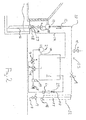
- FIG. 1 of the drawing appears a schematic drawing showing valve arrangements and piping for a slurry tanker according to prior art.
- Tank 1 of slurry tanker to be filled When ejector 6 is to be used, one has to start with a suitable amount of liquid in the tank 1.
- Slurry pump 2 pumping slurry out of the slurry tank 1 via a discharge line 49.
- the slurry pump 2 is therefore an emptying pump.
- the emptying pump 2 can be driven by hydraulics, electricity or the power take-off of the tractor.
- Three-way valve 3 that may be used for choosing between using ejector system or normal spreading.
- Three-way valve 4 used for regulation of dose when spreading on a field.
- Ejector 6 used at initial suction for filling the tank 1. By circulating through the ejector 6, vacuum arises in suction line 51 and in valves 7 and 9. The ejector 6 is disposed in a return line 50 to the tank 1.
- Slurry valve 7 providing the possibility of sucking through hose, e.g. manually mounted for emptying from smaller containers (not shown).
- Coupling 8 for use in mounting hose.
- Slurry valve 9 provides the possibility of sucking through suction line/hose 20 on the top arm of the slurry tanker which in a known way is coupled to the funnel 28 with associated suction line disposed in a slurry container 16 to be emptied.
- Slurry valve 10 which closes normal connection between a feed line 48 and the hose 20 on the top arm of the slurry tanker to the tank 1 of the slurry tanker. By closed slurry valve 10, the slurry can be aspirated and lifted up to a non-self-priming filling pump 13.
- Air valve 11 which is closed when sucking, and which is opened when the tank 1 is full so that the slurry in the hose 20 of the top arm can run back to the slurry container 16.
- the air valve provides for avoiding siphoning effect and emptying the tank 1 of the slurry tanker.
- the slurry from the top arm hose 20 is delivered deeply in the slurry tanker tank 1 in order to avoid foaming.
- Extension 12 on the top arm for adapting to various positions of slurry containers 16.
- the extension 12 is to be 100% tight in order to obtain aspiration.
- Filling pump 13 which is normally submerged in the slurry in the slurry container 16.
- the filling pump is not self-priming and is preferably liquid-driven.
- Slurry valve 14 disposed at the extreme end of the hose 20. By closing the slurry valve 14, one may let the hose 20 of the top arm be full with slurry after filling. With the valve 14 closed, the top arm may be aspirated during transport. Thereby, the aspiration time is reduced at the next filling. When the valve 14 is closed, waste is also reduced when coupling 27 and 28 are separated.
- the coupling 27 is to be tight in order to obtain enough vacuum to lift the slurry up from the slurry container 16 to the filling pump 13. This normally occurs by pressing the top arm coupling 27 against the coupling 28 of the slurry container.
- the coupling 27 is equipped with a flexible rubber joint 15.
- Flow meter 17 measuring the amount of slurry spread.
- valves 3, 4, 9, 11, 14 are remotely controlled as they are to be operated at each filling of the tank 1.
- the valves 7, 9 are normally manually operated, as they are only operated in another method of filling.
- a return line 50 to the tank is provided in connection with the emptying pump 2.
- an ejector 6 is disposed and connected to a pressure source for a medium for establishing ejector action.
- the ejector has a suction line 51 which via a shut-off valve 9 can be connected to the filling pump 13 for aspirating the slurry through the filling pump 13.
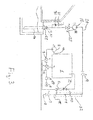
- Fig. 2 shows a schematic drawing corresponding to Fig. 1 of an arrangement according to the present invention.
- a schematic drawing for the arrangement in a tanker is shown here with a top arm with the hose 20 and the extension 12.
- the top arm can be of the type without extension.
- this arrangement is modified in that the side line from the suction line 51 with the valve 10 is omitted such that only the suction line 51 is used for filling the tank 1.
- the feed line is, as shown with broken lines, a manifold 52 only constituting a part of the suction line 51.
- the manifold 52 will preferably be a container which is permanently connected with the tank 1.
- the valve 3 in the return line may remain open for maintaining the ejector action throughout the filling of the entire tank.
- the suction line 51 is now supplied with the liquid under pressure from the filling pump 13, thereby in principle acting as feed line to the tank 1.
- the capacity of the filling pump 13 is higher than the capacity of the ejector 6. This means that the emptying pump 2 only gives a small contribution to the filling when running. It will be possible to switch off the ejector by closing the valve 3 in the return line 50 and at the same time stop the emptying pump 2.
- shut-off valve 29 In front of the outlet of the ejector is disposed a shut-off valve 29.
- the shut-off valve 29 may alternatively be disposed between the ejector and the manifold 52.
- the shut-off valve is used for shutting off such that a residual amount of slurry will remain in the manifold 52 and possibly also in the ejector 6 such that a subsequent filling operation can be effected faster.
- the outlet opening from the manifold is disposed at the bottom of a box-shaped manifold such that a considerable residual amount of slurry can be retained in the manifold 52.
- FIG. 3 shows another schematic drawing corresponding to Fig. 1 of an arrangement according to the present invention.
- a schematic drawing for the arrangement in a tanker is shown here with a side arm 25 with the hose 20.
- valve 14 in a side line for the hose 20 there is provided a check valve 30 and a shut-off valve 31.
- valve 14 When aspirating and filling with filling pump 13, valve 14 is open and valve 31 is closed.
- valve 31 When the filling is ended and before separation of couplings 27 and 28, valve 14 is closed and valve 31 is opened such that the amount of slurry under valve 14 is allowed to return to the container 16, and waste is avoided.
- check valve 30 prevents the slurry from running out of valve 31 when the latter is opened at the same time as the valve 14 is closed.
- coupling 28 is provided with a shut-off valve.
- the arrangement shown in Fig. 3 is also modified in that the side line with the valve 10 is omitted such that only the suction line 51 is used for filling the tank 1.
- the feed line is, as shown with broken lines, with a manifold 52 just constituting a part of the suction line 51.
- Fig. 4 shows a slurry tanker with an arrangement according to the present invention.
- the slurry tanker is towed by tractor via a drawbar 21.
- the emptying pump 2 has a shaft 22 connected with power take-off on the tractor.
- the slurry tanker has a top arm 23 supporting the hose 20 and connected to a return line 19 for returning excessive slurry and foam to the container 16.
- the slurry tanker is provided with a side arm 25 which via a pivot joint 26 is connected with the feed line which is here provided as a container-shaped housing 52 at the front end of the slurry tanker.
- the side arm 25 is provided with a filling pump 13 being a side arm pump which is not self-priming, and which therefore also can be primed by means of the ejector 6 by setting the valves of the arrangement.
- the slurry tanker can therefore optionally be filled by means of the filling pump 13 or only by the ejector if the slurry is not pumpable with the filling pump 13.
- Figs. 5-8 show perspective views that are partially transparent for more clearly showing the arrangement in Fig. 4 . Thus no detailed explanation is given to each of these Figures.
- the slurry is spread on the field.
- an appropriate amount of slurry is left in the tank 1 of the slurry tanker, the spreading is stopped, and one returns to the slurry container 16 which is to be emptied.
- an appropriate amount is meant an amount which is sufficient to get the ejector 6 to operate in a satisfactory way. Part of or all of this residual amount can be located in the manifold 52.
- the valve 9 is opened.
- the top arm places the coupling 27 in filling position so that the coupling 27 is tight. This normally occurs by pressing the top arm coupling 27 against the coupling 28 of the slurry container.
- the flexible rubber joint 15 is necessary for the system to operate when the slurry tanker rocks and sinks down in the suspension due to increased load.
- the top arm can have appreciable length, and therefore the position of the coupling 27 can be released from engagement with the coupling 28 of the slurry container if the flexible rubber joint 15 had not been provided.
- the valve 14 is opened and, like the valve 9, is to stay in this open position during the entire filling operation.
- the valve 11 is shut.
- the slurry tanker is now ready for filling by using the ejector 6. This is done by activating the emptying pump 2 with the valve 3 in a position connecting the emptying pump 2 with the ejector 6.
- the emptying pump 2 is started, and vacuum appears in the connection down to the coupling 27 by the flow of the slurry through the ejector 6 and back to the slurry tanker tank 1.
- the vacuum has become sufficiently high (can be read on the manometer 18)
- the slurry is lifted up to the filling pump 13 of the top arm.
- the filling pump 13 of the top arm is started simultaneously with the emptying pump 2.
- the filling pump 13 of the top arm will pump slurry from the container 16 directly into the tank 1 of the slurry tanker via the ejector 6.
- the filling pump 13 of the top arm can be stopped simultaneously with opening the valve 11.
- air may come into the top arm hose 20, and the slurry in the top arm hose 20 can run out without risking start of emptying the tank 1 again due to a siphoning effect.
- a valve 14 which will close when the tank 1 is full. Closing the valve 14 will also obviate the risk of emptying the tank 1 due to siphoning effect.
- the top arm is placed in driving position on the slurry tanker.
- the valve 3 changes position so that the slurry can be spread out on the field.
Abstract
- a feed line 52) with a filling pump (3) for pumping the liquid to the tank (1);
- a discharge line (49) with an emptying pump (2) for pumping the liquid out of the tank (1);
- a return line (50) to the tank (1) associated with the emptying pump (2);
- an ejector (6) provided in the return line (50);
- a suction line (51) connected with the suction side of the ejector (6) for aspirating the liquid through the filling pump (13); and
- valves (3,9,29) for shutting off/opening connections between the ejector, the pumps and the tank
Description
- The present invention concerns an arrangement for filling a tank in a tanker, preferably a slurry tanker, with liquid such as water containing varying amounts of contaminants, the arrangement including:
- a feed line with a filling pump for pumping the liquid to the tank;
- a discharge line with an emptying pump for pumping the liquid out of the tank;
- a return line to the tank associated with the emptying pump;
- an ejector provided in the return line;
- a suction line connected with the suction side of the ejector for aspirating the liquid through the filling pump; and
- valves for optionally shutting off/opening connections between the ejector, the pumps and the tank.
- The invention furthermore concerns a method for filling a tank in a tanker, preferably a slurry tanker, with liquid such as water containing varying amounts of contaminants, which tank is connected with an arrangement including:
- a feed line with a filling pump for pumping the liquid to the tank;
- a discharge line with an emptying pump for pumping the liquid out of the tank;
- a return line to the tank associated with the emptying pump;
- an ejector provided in the return line;
- a suction line connected with the suction side of the ejector for aspirating the liquid through the filling pump; and
- valves for optionally shutting off/opening connections between the ejector, the pumps and the tank;
- The pump arrangements of the kind mentioned in the introduction are particularly suitable in the agricultural area. The liquid will therefore often be slurry. However, the system can also find application in connection with other liquids that contain varying amounts of contaminants that may have influence on the pumps.
- Various types of filling pumps are known. Some of these are mounted on the tanker, e.g. via a top arm, which is disposed upon the tank, or other filling pumps mounted stationary in the containers containing the liquid to be pumped into the tank.
- It is known with systems arranged with an air vacuum pump which establishes an underpressure in the whole tank. The entire tank is then, however, to be a pressurised container which may give rise to safety concerns.
- A different system for filling the tank is to use shear pumps which can be of screw or rotary piston type. These will usually also be mounted on the tanker and be powered by the engine of a tractor towing the tanker or by the engine of a self-propelled tanker. If the case is a tractor- towed tanker, the power take-off of the tractor will usually be applied to drive such a pump. Such a pump will usually have capacity to pump air and suck out the air initially found in the piping system that connects the tank with the container to be emptied, which is often disposed at a lower level and often at a distance from the pump itself. These pump types, however, have the drawback that they are prone to become damaged if they run dry, and they can be damaged by solids in the liquid as well.
- Another type of pump, namely centrifugal or turbo pumps, are also used. However, these cannot evacuate the air found in the pipe system. Such pumps will therefore be adapted to be submerged into the liquid to be pumped into the tank and therefore be connected with the outermost end of the lines, which usually is a top arm as mentioned above. Such a pump is commonly driven by a hydraulic motor which is supplied with drive fluid from a tractor or a self-propelled tanker. However, the centrifugal pump can also be mounted on the tanker in the same way as a displacement pump and can be driven in the same way. In this situation it is required that the pump and the suction line at first are primed with liquid in one or the other way in order to enable the pump to suck the liquid from the container into the tank. For this application, use of an ejector has been suggested previously. An emptying pump used for emptying the tank is applied when a return line to the tank has been provided. When the ejector is disposed in a return line to the tank, it will be possible to use a residual amount of liquid in the tank which via the emptying pump is pumped through the return line and thereby the ejector. When the suction side of the ejector is connected with a feed line in which the filling pump is disposed, a priming of the filling pump as well as suction line and feed line to the tank will be effected. Such a system is e.g. described in
WO 03/083310 WO 07/143994 - By the prior art systems it is thus proposed that after aspirating the filling pump and the lines to the tank, a switching is performed such that the filling pump is used for filling the tank.
- In the prior art systems, in the discharge line at the delivery side of the emptying pump there will be provided a valve that can be set to send the liquid through the ejector or to shut off the ejector and send the liquid through the discharge line for emptying the tank. This can e.g. be effected when spreading on a field, but alternatively also just by emptying the liquid from the tank into a receiving container.
- In the feed line on the delivery side of the filling pump a valve is provided. This valve shuts off the feed line at start-up during aspiration of the filling pump and the feed line. After aspiration, the setting of this valve is changed such that the connection to the filling pump is opened, and the feed line is connected directly to the tank hereby.
- By such a system it is possible to fill a tanker by means of a non-self-priming filling pump, even if this filling pump cannot be submerged in the liquid to be pumped into the tank. The filling pump may thus be filled with liquid without having to be lowered into the liquid container.
- In order to fill the pump with liquid without need to submerge it into the liquid container, a return line to the tank is provided in connection with the emptying pump. In this return line an ejector is provided, connected to a pressure source for a medium for establishing ejector action. The ejector has a suction line which via a shut-off valve can be connected to the filling pump for aspirating the liquid through the filling pump.
- The ejector/ejector action provides for filling the filling pump after which it can be used for filling the tank in the usual way. The medium used for establishing the ejector action may either be a residual amount of liquid in the tank or pressurised air from a compressor.
- As mentioned, the time used for pumping and filling the tank should be reduced as much as possible. It is therefore desired to use a filling pump with high capacity.
- However, by the prior art systems there will also be a risk that the filling pump can become clogged when large lumps of contamination arrive and/or there is a risk of cavitation of the filling pump. The capacity is appreciably reduced hereby, and since the ejector is uncoupled, a restart will be required if the feed line and/or the filling pump runs dry. Therefore it is realised that it may be advantageous to keep the emptying pump running so that the ejector is kept activated. However, this requires a complicated control of valves between the feed line and the tank. As the efficiency of a filling pump, which is a centrifugal pump, is typically about 5 times greater than the efficiency of an ejector, it is desirable that filling is performed by the filling pump and that the latter is kept running during the filling of the tank.
- It is desired to reduce the number of valves and the need for control and thereby to achieve a more robust arrangement with possible reliability contributing to optimise the time that is used for filling the tank.
- It is the object of the present invention to indicate an arrangement of the kind indicated in the introduction where these drawbacks are relieved and to indicate an arrangement which is more simple and which has greater reliability than the prior art arrangements.
- This is achieved according to the present invention by an arrangement of the kind mentioned in the introduction which is peculiar in that the suction line is identical to the feed line such that the filling pump only pumps liquid to the tank via the ejector.
- The method according to the invention is peculiar in that the liquid is only pumped to the tank via the ejector as the suction line is identical to the feed line.
- By a system according to the invention it is still possible to fill a tanker by means of a non-self-priming filling pump, even if this filling pump cannot be submerged in the liquid to be pumped into the tank. The filling pump may thus be filled with liquid without needing to be lowered into the liquid container.
- When the filling pump is aspirated and actively pumps liquid into the tank, the liquid will continuously be pumped into the tank via the ejector. The suction line is now supplied with the liquid under pressure from the filling pump, thereby in principle acting as feed line to the tank. The capacity of the filling pump is greater than the capacity of the ejector. This means that the emptying pump via the ejector only provides a small contribution to the filling.
- It will be possible to switch off the ejector by closing the valve in the return line and at the same time stop the emptying pump.
- In practice it is preferred that the valve in the return line is kept open. Filling of the tanks will hereby not occur by means of the filling pump only. The ejector will still be active as the emptying pump is still activated and thereby pumps liquid through the return line, producing an ejector action that contributes to the filing of the tank. Filling of the tank can thus be effected with contributions from both the ejector and the filling pump which are both filling the tank. The time used for filling the tank is reduced hereby.
- If the filling pump cavitates, the ejector action will ensure continued filling of the tank and aspiration of the filling pump such that the latter will automatically take over the greater part of the filling again without any need for controlling valves. In this situation it will thus also be possible to reduce the time used for filling the tank. Filling can alternatively occur by ejector action only.
- According to a further embodiment, the method according to the invention is peculiar in that the liquid is pumped into the tank via a feed manifold having an outlet opening that opens into the tank, and that the feed manifold has inlet openings that are optionally connected with a filling pump in a side arm or in a top arm, or is connected with a suction hose without a filling pump by suitable setting of the valves of the arrangement.
- According to a further embodiment, the method according to the invention is peculiar in that the feed line includes a feed manifold having an outlet opening that opens onto the tank, and inlet openings that are optionally connected with a filling pump in a side arm or in a top arm, or is connected with a suction hose without a filling pump, respectively.
- By using a feed manifold, this may be provided a proper size so as to contain a sufficient amount of liquid for aspirating the filling pump. A user of the tanker therefore does not need to terminate spreading the liquid from the tank in order to ensure presence of a residual amount sufficient for aspiration being left in the tank. The tank may simply be emptied completely. Such an assessment can be difficult and provide a risk of an insufficient residual amount left in the tank or of too large a residual amount left such that the tank capacity is not utilised optimally.
- The outlet to the tank from the feed manifold passes through the suction side of the ejector and on through the outlet from the ejector. Usually, a shut-off valve will be provided either before the outlet of the ejector or between the ejector and the manifold for retaining slurry in the manifold and possibly in the ejector as well. The filling process is hereby initiated faster.
- According to a further embodiment, the arrangement according to the invention is peculiar by further including a side arm line with a filling pump, which is a side arm pump, for pumping the liquid to the tank, and a valve for optionally shutting off/opening the inlet opening between the side arm line and the feed line. The tanker can hereby optionally be used for filling by means of the filling pump which is associated with a top arm (called a pump tower by some producers) disposed upon the tank or by means of the side arm line and the filling pump of the side arm. In both cases the emptying pump and the ejector will be used for aspirating the filling pump and contribute to filling the tank. Alternatively, these arrangements can be combined with a suction hose operating by ejector action only without a filling pump.
- According to a further embodiment, the arrangement according to the invention is peculiar in that between the side arm line and the feed line and the feed manifold, respectively, there is provided a pivot joint allowing the side arm line to pivot, preferably in a vertical plane, relative to the feed line and the feed manifold, respectively. The side arm line can hereby in a simple way be pivoted out from the tank into a suitable angular position when filling the tank and back to a position in front of the tank such that the width of the tanker is not increased during transport.
- According to a further embodiment, the arrangement according to the invention is peculiar in that the feed manifold is permanently connected with the tank at this front end and that the outlet opening of the feed manifold opens onto the bottom of the tank.
- According to a further embodiment, the arrangement according to the invention is peculiar in that the tanker is a slurry tanker and that the ejector is provided inside the tank at a position close to the bottom thereof. By disposing the ejector and the inlet for the tank close to the bottom of the tank, foaming will be reduced when the slurry tanker is filled.
- Alternatively, the ejector can also be located outside the tank.
- The invention will be explained in more detail below with reference to the accompanying drawing, wherein:
- Fig. 1
- shows a schematic drawing of a tanker in the form of a slurry tanker according to prior art;
- Figs. 2-3
- show schematic drawings corresponding to
Fig. 1 of a slurry tanker with an arrangement according to the present invention; - Fig. 4
- shows a perspective view of a slurry tanker with an arrangement according to the invention; and
- Figs. 5-8
- show partially transparent, perspective views of an arrangement for the slurry tanker shown in
Fig. 4 . - Identical or corresponding elements will be designated with the same reference numerals in the different figures of the drawing.
- In
Fig. 1 of the drawing appears a schematic drawing showing valve arrangements and piping for a slurry tanker according to prior art. - This arrangement is shown in modified from in
Figs. 2 and3 . - In
Fig. 1 , the following elements appear: -
Tank 1 of slurry tanker to be filled. Whenejector 6 is to be used, one has to start with a suitable amount of liquid in thetank 1. -
Slurry pump 2 pumping slurry out of theslurry tank 1 via adischarge line 49. Theslurry pump 2 is therefore an emptying pump. The emptyingpump 2 can be driven by hydraulics, electricity or the power take-off of the tractor. - Three-
way valve 3 that may be used for choosing between using ejector system or normal spreading. - Three-
way valve 4 used for regulation of dose when spreading on a field. - Spreader 5 for spreading on field.
-
Ejector 6 used at initial suction for filling thetank 1. By circulating through theejector 6, vacuum arises insuction line 51 and in valves 7 and 9. Theejector 6 is disposed in areturn line 50 to thetank 1. - Slurry valve 7 providing the possibility of sucking through hose, e.g. manually mounted for emptying from smaller containers (not shown).
-
Coupling 8 for use in mounting hose. - Slurry valve 9 provides the possibility of sucking through suction line/
hose 20 on the top arm of the slurry tanker which in a known way is coupled to thefunnel 28 with associated suction line disposed in aslurry container 16 to be emptied. -
Slurry valve 10 which closes normal connection between afeed line 48 and thehose 20 on the top arm of the slurry tanker to thetank 1 of the slurry tanker. Byclosed slurry valve 10, the slurry can be aspirated and lifted up to a non-self-priming filling pump 13. -
Air valve 11 which is closed when sucking, and which is opened when thetank 1 is full so that the slurry in thehose 20 of the top arm can run back to theslurry container 16. The air valve provides for avoiding siphoning effect and emptying thetank 1 of the slurry tanker. The slurry from thetop arm hose 20 is delivered deeply in theslurry tanker tank 1 in order to avoid foaming. -
Extension 12 on the top arm for adapting to various positions ofslurry containers 16. Theextension 12 is to be 100% tight in order to obtain aspiration. - Filling
pump 13 which is normally submerged in the slurry in theslurry container 16. The filling pump is not self-priming and is preferably liquid-driven. -
Slurry valve 14 disposed at the extreme end of thehose 20. By closing theslurry valve 14, one may let thehose 20 of the top arm be full with slurry after filling. With thevalve 14 closed, the top arm may be aspirated during transport. Thereby, the aspiration time is reduced at the next filling. When thevalve 14 is closed, waste is also reduced when coupling 27 and 28 are separated. - Coupling 27 towards the
slurry container 16. The coupling 27 is to be tight in order to obtain enough vacuum to lift the slurry up from theslurry container 16 to the fillingpump 13. This normally occurs by pressing the top arm coupling 27 against thecoupling 28 of the slurry container. The coupling 27 is equipped with a flexible rubber joint 15. -
Flow meter 17 measuring the amount of slurry spread. - Manometer 18.
-
Return line 19 from theslurry tanker tank 1 to theslurry container 16. - Normally, the
valves tank 1. The valves 7, 9 are normally manually operated, as they are only operated in another method of filling. - In order to fill the filling
pump 13 with slurry without the need of lowering into theslurry container 16, areturn line 50 to the tank is provided in connection with the emptyingpump 2. In thisreturn line 50, anejector 6 is disposed and connected to a pressure source for a medium for establishing ejector action. The ejector has asuction line 51 which via a shut-off valve 9 can be connected to the fillingpump 13 for aspirating the slurry through the fillingpump 13. -
Fig. 2 shows a schematic drawing corresponding toFig. 1 of an arrangement according to the present invention. A schematic drawing for the arrangement in a tanker is shown here with a top arm with thehose 20 and theextension 12. - Alternatively, the top arm can be of the type without extension.
- Compared with the prior art arrangement, this arrangement is modified in that the side line from the
suction line 51 with thevalve 10 is omitted such that only thesuction line 51 is used for filling thetank 1. The feed line is, as shown with broken lines, a manifold 52 only constituting a part of thesuction line 51. - The manifold 52 will preferably be a container which is permanently connected with the
tank 1. - The
valve 3 in the return line may remain open for maintaining the ejector action throughout the filling of the entire tank. Thesuction line 51 is now supplied with the liquid under pressure from the fillingpump 13, thereby in principle acting as feed line to thetank 1. The capacity of the fillingpump 13 is higher than the capacity of theejector 6. This means that the emptyingpump 2 only gives a small contribution to the filling when running. It will be possible to switch off the ejector by closing thevalve 3 in thereturn line 50 and at the same time stop the emptyingpump 2. - In front of the outlet of the ejector is disposed a shut-off
valve 29. The shut-offvalve 29 may alternatively be disposed between the ejector and the manifold 52. The shut-off valve is used for shutting off such that a residual amount of slurry will remain in the manifold 52 and possibly also in theejector 6 such that a subsequent filling operation can be effected faster. In practice, the outlet opening from the manifold is disposed at the bottom of a box-shaped manifold such that a considerable residual amount of slurry can be retained in themanifold 52. After finishing filling of thetank 1, thevalve 29 is closed and thevalve 3 is set in position for spreading. -
Fig. 3 shows another schematic drawing corresponding toFig. 1 of an arrangement according to the present invention. A schematic drawing for the arrangement in a tanker is shown here with aside arm 25 with thehose 20. There is no extension here, but theside arm 25 may alternatively be provided with an extension. - After the
valve 14, in a side line for thehose 20 there is provided acheck valve 30 and a shut-offvalve 31. When aspirating and filling with fillingpump 13,valve 14 is open andvalve 31 is closed. When the filling is ended and before separation ofcouplings 27 and 28,valve 14 is closed andvalve 31 is opened such that the amount of slurry undervalve 14 is allowed to return to thecontainer 16, and waste is avoided. When filling from containers above the ground where a pressure above atmospheric pressure is present atcoupling 28,check valve 30 prevents the slurry from running out ofvalve 31 when the latter is opened at the same time as thevalve 14 is closed. By tanks above the ground,coupling 28 is provided with a shut-off valve. - The arrangement shown in
Fig. 3 is also modified in that the side line with thevalve 10 is omitted such that only thesuction line 51 is used for filling thetank 1. The feed line is, as shown with broken lines, with a manifold 52 just constituting a part of thesuction line 51. - The mode of operation will be analogous to the one described for the arrangement shown in
Fig. 2 . -
Fig. 4 shows a slurry tanker with an arrangement according to the present invention. The slurry tanker is towed by tractor via adrawbar 21. The emptyingpump 2 has ashaft 22 connected with power take-off on the tractor. The slurry tanker has atop arm 23 supporting thehose 20 and connected to areturn line 19 for returning excessive slurry and foam to thecontainer 16. - At the front end, the slurry tanker is provided with a
side arm 25 which via a pivot joint 26 is connected with the feed line which is here provided as a container-shapedhousing 52 at the front end of the slurry tanker. Theside arm 25 is provided with a fillingpump 13 being a side arm pump which is not self-priming, and which therefore also can be primed by means of theejector 6 by setting the valves of the arrangement. The slurry tanker can therefore optionally be filled by means of the fillingpump 13 or only by the ejector if the slurry is not pumpable with the fillingpump 13. -
Figs. 5-8 show perspective views that are partially transparent for more clearly showing the arrangement inFig. 4 . Thus no detailed explanation is given to each of these Figures. - In the following there is described a situation of use of the arrangement according to the invention where no risk of cavitation exist.
- The slurry is spread on the field. When an appropriate amount of slurry is left in the
tank 1 of the slurry tanker, the spreading is stopped, and one returns to theslurry container 16 which is to be emptied. By an appropriate amount is meant an amount which is sufficient to get theejector 6 to operate in a satisfactory way. Part of or all of this residual amount can be located in themanifold 52. - The valve 9 is opened.
- The top arm places the coupling 27 in filling position so that the coupling 27 is tight. This normally occurs by pressing the top arm coupling 27 against the
coupling 28 of the slurry container. - The flexible rubber joint 15 is necessary for the system to operate when the slurry tanker rocks and sinks down in the suspension due to increased load. The top arm can have appreciable length, and therefore the position of the coupling 27 can be released from engagement with the
coupling 28 of the slurry container if the flexible rubber joint 15 had not been provided. - The
valve 14 is opened and, like the valve 9, is to stay in this open position during the entire filling operation. Thevalve 11 is shut. - The slurry tanker is now ready for filling by using the
ejector 6. This is done by activating the emptyingpump 2 with thevalve 3 in a position connecting the emptyingpump 2 with theejector 6. - The emptying
pump 2 is started, and vacuum appears in the connection down to the coupling 27 by the flow of the slurry through theejector 6 and back to theslurry tanker tank 1. When the vacuum has become sufficiently high (can be read on the manometer 18), the slurry is lifted up to the fillingpump 13 of the top arm. - The filling
pump 13 of the top arm is started simultaneously with the emptyingpump 2. - When the slurry comes up to the filling
pump 13, it will pump the slurry faster into thetank 1 of the slurry tanker than allowed by the capacity of theejector 6, and the vacuum on the manometer 18 will drop. - When the filling
pump 13 is filled with slurry, the fillingpump 13 of the top arm will pump slurry from thecontainer 16 directly into thetank 1 of the slurry tanker via theejector 6. - When the
slurry tanker tank 1 is full, thereturn line 19 will make the slurry run back to theslurry container 16, and possible foam formation will come out of the slurry tanker tank. Thereby 100% filling is attained. - When the
tank 1 of the slurry tanker is full, the fillingpump 13 of the top arm can be stopped simultaneously with opening thevalve 11. Hereby, air may come into thetop arm hose 20, and the slurry in thetop arm hose 20 can run out without risking start of emptying thetank 1 again due to a siphoning effect. Alternatively, there may be used avalve 14 which will close when thetank 1 is full. Closing thevalve 14 will also obviate the risk of emptying thetank 1 due to siphoning effect. - The top arm is placed in driving position on the slurry tanker.
- The
valve 3 changes position so that the slurry can be spread out on the field. - Then the above operations can be repeated.
Claims (10)
- An arrangement for filling a tank (1) of a tanker, preferably a slurry tanker, with liquid such as water containing varying amounts of contaminants, the arrangement including:- a feed line (52) with a filling pump (13) for pumping the liquid to the tank (1);- a discharge line (49) with an emptying pump (2) for pumping the liquid out of the tank (1);- a return line (50) to the tank (1) associated with the emptying pump (2);- an ejector (6) provided in the return line (50);- a suction line (51) connected with the suction side of the ejector (6) for aspirating the liquid through the filling pump (13); and- valves (3, 9, 29) for optionally shutting off/opening connections between the ejector, the pumps and the tank;characterised in that the suction line (51) is identical to the feed line (52) such that the filling pump (13) only pumps liquid to the tank (1) via the ejector (6).
- Arrangement according to claim 1, characterised in that the feed line (52) includes a feed manifold (52) having an outlet opening that opens onto the tank (1), and inlet openings that are optionally connected with a filling pump (13) in a side arm (25) or in a top arm (23), or is connected with a suction hose without a filling pump, respectively.
- Arrangement according to claim 1 or 2, characterised by further including a side arm line on a side arm (25) with a filling pump (13) constituting a side arm pump for pumping the liquid to the tank (1), and a valve (14) for optionally shutting off/opening the inlet opening between the side arm line and the feed line (52).
- Arrangement according to claim 2 or 3, characterised in that between the side arm line and the feed line and the feed manifold (52), respectively, there is provided a pivot joint (26) allowing the side arm line to pivot, preferably in a vertical plane, relative to the feed line and the feed manifold (52), respectively.
- Arrangement according to claim 2, 3 or 4, characterised in that the feed manifold (52) is permanently connected with the tank (1) at this front end and that the outlet opening of the feed manifold (52) opens onto the bottom of the tank (1).
- Arrangement according to any preceding claim 2-5, characterised in that a shut-off valve (29) is disposed either before the outlet of the ejector (6) or between the ejector (6) and the feed manifold (52).
- A method for filling a tank (1) in a tanker, preferably a slurry tanker, with liquid such as water containing varying amounts of contaminants, which tank is connected with an arrangement including:- a feed line (52) with a filling pump (13) for pumping the liquid to the tank (1);- a discharge line (49) with an emptying pump (2) for pumping the liquid out of the tank (1);- a return line (50) to the tank (1) associated with the emptying pump (2);- an ejector (6) provided in the return line (50);- a suction line (51) connected with the suction side of the ejector for aspirating the liquid through the filling pump (13); and- valves (3, 9, 29) for optionally shutting off/opening connections between the ejector (6), the pumps (3, 9, 29) and the tank (1);by which method there is provided an ejector action in a return line (59) connecting the emptying pump (2) with the tank (1), wherein this ejector action is used for establishing a vacuum in the suction line (51) for aspirating the liquid through the filling pump (13), characterised in that the liquid is only pumped to the tank (1) via the ejector as the suction line (51) is identical to the feed line (52).
- Method according to claim 7, characterised in that the liquid is pumped into the tank (1) via a feed manifold (52) having an outlet opening that opens into the tank (1), and that the feed manifold (52) has inlet openings that are optionally connected with a filling pump (13) in a side arm (25) or in a top arm (23), or is connected with a suction hose without a filling pump by suitably setting the valves of the arrangement.
- Method according to claim 7 or 8, wherein the tanker is a slurry tanker.
- A slurry tanker with an arrangement according to any of claims 1-6.
Applications Claiming Priority (1)
| Application Number | Priority Date | Filing Date | Title |
|---|---|---|---|
| DK201370659A DK178045B1 (en) | 2013-11-08 | 2013-11-08 | Arrangement for filling a tank in a tanker vehicle, preferably a slurry and method for filling such a tank |
Publications (2)
| Publication Number | Publication Date |
|---|---|
| EP2870851A1 true EP2870851A1 (en) | 2015-05-13 |
| EP2870851B1 EP2870851B1 (en) | 2018-12-19 |
Family
ID=52006791
Family Applications (1)
| Application Number | Title | Priority Date | Filing Date |
|---|---|---|---|
| EP14192275.7A Active EP2870851B1 (en) | 2013-11-08 | 2014-11-07 | Arrangement for filling a tank on a tanker, preferably a slurry tanker, and method for filling such a tank |
Country Status (3)
| Country | Link |
|---|---|
| EP (1) | EP2870851B1 (en) |
| DK (2) | DK178045B1 (en) |
| ES (1) | ES2714288T3 (en) |
Cited By (4)
| Publication number | Priority date | Publication date | Assignee | Title |
|---|---|---|---|---|
| CN105660024A (en) * | 2016-01-06 | 2016-06-15 | 东莞一翔液体肥料有限公司 | Rice fertilization-with-water device |
| EP3058800A1 (en) | 2015-02-20 | 2016-08-24 | Leonard Dancey | An impeller pump |
| CN105940843A (en) * | 2016-06-02 | 2016-09-21 | 山东农业大学 | Water and fertilizer integration remote control and intelligent management system |
| EP3225091A1 (en) * | 2016-03-30 | 2017-10-04 | Harry Højvang Sørensen | A slurry pump with a flap valve |
Families Citing this family (1)
| Publication number | Priority date | Publication date | Assignee | Title |
|---|---|---|---|---|
| DE202021001741U1 (en) | 2021-05-14 | 2021-06-08 | Andreas Demmler | Tank filling system with venturi suction vent |
Citations (4)
| Publication number | Priority date | Publication date | Assignee | Title |
|---|---|---|---|---|
| DE2451529A1 (en) * | 1974-10-30 | 1976-05-06 | Hans Beham | Filling and discharge system for mobile slurry tank - has solids trap at rear with upper suction chamber, pump and valves below |
| DE4108549C1 (en) * | 1991-03-15 | 1992-05-21 | Deutsche Airbus Gmbh, 2000 Hamburg, De | |
| WO2004010006A1 (en) * | 2002-07-19 | 2004-01-29 | Walker-Dawson Interests, Inc. | Recirculating jet pump and method of moving material |
| WO2007143994A1 (en) * | 2006-06-15 | 2007-12-21 | Samson Agro A/S | Slurry tanker with ejector and method for filling a tank on the slurry tanker |
Family Cites Families (3)
| Publication number | Priority date | Publication date | Assignee | Title |
|---|---|---|---|---|
| SU533352A1 (en) * | 1974-04-08 | 1976-10-30 | Всесоюзный Ордена Трудового Красного Знамени Научно-Исследовательский Институт Механизации Сельского Хозяйства | Liquid Fertilizer Spreader |
| DE29922096U1 (en) * | 1999-12-16 | 2000-03-02 | Zunhammer Sebastian | Liquid tank |
| FR2964643B1 (en) * | 2010-09-10 | 2013-12-27 | Lequien | SYSTEM AND METHOD FOR FILLING A CONTAINER, IN PARTICULAR A SLICER TON |
-
2013
- 2013-11-08 DK DK201370659A patent/DK178045B1/en not_active IP Right Cessation
-
2014
- 2014-11-07 EP EP14192275.7A patent/EP2870851B1/en active Active
- 2014-11-07 ES ES14192275T patent/ES2714288T3/en active Active
- 2014-11-07 DK DK14192275.7T patent/DK2870851T3/en active
Patent Citations (4)
| Publication number | Priority date | Publication date | Assignee | Title |
|---|---|---|---|---|
| DE2451529A1 (en) * | 1974-10-30 | 1976-05-06 | Hans Beham | Filling and discharge system for mobile slurry tank - has solids trap at rear with upper suction chamber, pump and valves below |
| DE4108549C1 (en) * | 1991-03-15 | 1992-05-21 | Deutsche Airbus Gmbh, 2000 Hamburg, De | |
| WO2004010006A1 (en) * | 2002-07-19 | 2004-01-29 | Walker-Dawson Interests, Inc. | Recirculating jet pump and method of moving material |
| WO2007143994A1 (en) * | 2006-06-15 | 2007-12-21 | Samson Agro A/S | Slurry tanker with ejector and method for filling a tank on the slurry tanker |
Cited By (4)
| Publication number | Priority date | Publication date | Assignee | Title |
|---|---|---|---|---|
| EP3058800A1 (en) | 2015-02-20 | 2016-08-24 | Leonard Dancey | An impeller pump |
| CN105660024A (en) * | 2016-01-06 | 2016-06-15 | 东莞一翔液体肥料有限公司 | Rice fertilization-with-water device |
| EP3225091A1 (en) * | 2016-03-30 | 2017-10-04 | Harry Højvang Sørensen | A slurry pump with a flap valve |
| CN105940843A (en) * | 2016-06-02 | 2016-09-21 | 山东农业大学 | Water and fertilizer integration remote control and intelligent management system |
Also Published As
| Publication number | Publication date |
|---|---|
| DK178045B1 (en) | 2015-04-13 |
| ES2714288T3 (en) | 2019-05-28 |
| DK2870851T3 (en) | 2019-02-18 |
| EP2870851B1 (en) | 2018-12-19 |
Similar Documents
| Publication | Publication Date | Title |
|---|---|---|
| EP2870851B1 (en) | Arrangement for filling a tank on a tanker, preferably a slurry tanker, and method for filling such a tank | |
| EP2223594B1 (en) | Agricultural sprayer | |
| DK2789232T3 (en) | Field sprayer. | |
| US8939637B2 (en) | Apparatus for mixing and pumping manure slurries | |
| US6547964B1 (en) | Mud tank cleaning system | |
| KR100984267B1 (en) | Sludge-transfer vehicle | |
| US4555063A (en) | Liquid waste agitating and pumping apparatus | |
| KR101104345B1 (en) | multipurpose dredging apparatus composed open circuit type hydraulic system | |
| WO2007143994A1 (en) | Slurry tanker with ejector and method for filling a tank on the slurry tanker | |
| US3136485A (en) | Self-loading liquid fertilizer spreader | |
| EP3225091B1 (en) | A slurry pump with a flap valve | |
| US3212822A (en) | Apparatus for pumping objects to higher levels | |
| US5498141A (en) | Hygienic tank lorry pump and tank truck | |
| CZ299206B6 (en) | Pumping set | |
| CN104136687A (en) | Method for filling and emptying a liquid tank of a spreader device for winter service vehicles, and spreader device | |
| WO2000064701A1 (en) | Loading device at a vakuumtanker vehicle | |
| NL1024403C2 (en) | Pump assembly, pumping mass transport device and method of use thereof. | |
| US2083582A (en) | Pumping system for gold dredges | |
| NL9300771A (en) | Tank device | |
| CN207660090U (en) | A kind of big flow movable type self-priming pump truck | |
| JP5887447B1 (en) | Water supply system | |
| NL1019411C2 (en) | Self-suction centrifugal pump has housing of which inner part is formed by pressure chamber and flexible suction hose is connected to housing suction connection | |
| WO2003083310A1 (en) | Loading pump device | |
| JP2001027194A (en) | Device and method for feeding and discharging lubricating oil in submerged pump | |
| DK174024B1 (en) | Tank vehicle with series-connected main and front pumps |
Legal Events
| Date | Code | Title | Description |
|---|---|---|---|
| PUAI | Public reference made under article 153(3) epc to a published international application that has entered the european phase |
Free format text: ORIGINAL CODE: 0009012 |
|
| 17P | Request for examination filed |
Effective date: 20141107 |
|
| AK | Designated contracting states |
Kind code of ref document: A1 Designated state(s): AL AT BE BG CH CY CZ DE DK EE ES FI FR GB GR HR HU IE IS IT LI LT LU LV MC MK MT NL NO PL PT RO RS SE SI SK SM TR |
|
| AX | Request for extension of the european patent |
Extension state: BA ME |
|
| R17P | Request for examination filed (corrected) |
Effective date: 20151113 |
|
| RBV | Designated contracting states (corrected) |
Designated state(s): AL AT BE BG CH CY CZ DE DK EE ES FI FR GB GR HR HU IE IS IT LI LT LU LV MC MK MT NL NO PL PT RO RS SE SI SK SM TR |
|
| STAA | Information on the status of an ep patent application or granted ep patent |
Free format text: STATUS: EXAMINATION IS IN PROGRESS |
|
| 17Q | First examination report despatched |
Effective date: 20171025 |
|
| GRAP | Despatch of communication of intention to grant a patent |
Free format text: ORIGINAL CODE: EPIDOSNIGR1 |
|
| STAA | Information on the status of an ep patent application or granted ep patent |
Free format text: STATUS: GRANT OF PATENT IS INTENDED |
|
| INTG | Intention to grant announced |
Effective date: 20180712 |
|
| GRAS | Grant fee paid |
Free format text: ORIGINAL CODE: EPIDOSNIGR3 |
|
| GRAJ | Information related to disapproval of communication of intention to grant by the applicant or resumption of examination proceedings by the epo deleted |
Free format text: ORIGINAL CODE: EPIDOSDIGR1 |
|
| GRAL | Information related to payment of fee for publishing/printing deleted |
Free format text: ORIGINAL CODE: EPIDOSDIGR3 |
|
| STAA | Information on the status of an ep patent application or granted ep patent |
Free format text: STATUS: EXAMINATION IS IN PROGRESS |
|
| GRAP | Despatch of communication of intention to grant a patent |
Free format text: ORIGINAL CODE: EPIDOSNIGR1 |
|
| STAA | Information on the status of an ep patent application or granted ep patent |
Free format text: STATUS: GRANT OF PATENT IS INTENDED |
|
| INTC | Intention to grant announced (deleted) | ||
| GRAA | (expected) grant |
Free format text: ORIGINAL CODE: 0009210 |
|
| STAA | Information on the status of an ep patent application or granted ep patent |
Free format text: STATUS: THE PATENT HAS BEEN GRANTED |
|
| INTG | Intention to grant announced |
Effective date: 20181102 |
|
| AK | Designated contracting states |
Kind code of ref document: B1 Designated state(s): AL AT BE BG CH CY CZ DE DK EE ES FI FR GB GR HR HU IE IS IT LI LT LU LV MC MK MT NL NO PL PT RO RS SE SI SK SM TR |
|
| REG | Reference to a national code |
Ref country code: GB Ref legal event code: FG4D |
|
| REG | Reference to a national code |
Ref country code: CH Ref legal event code: EP |
|
| REG | Reference to a national code |
Ref country code: IE Ref legal event code: FG4D |
|
| REG | Reference to a national code |
Ref country code: DE Ref legal event code: R096 Ref document number: 602014038128 Country of ref document: DE |
|
| REG | Reference to a national code |
Ref country code: AT Ref legal event code: REF Ref document number: 1077689 Country of ref document: AT Kind code of ref document: T Effective date: 20190115 |
|
| REG | Reference to a national code |
Ref country code: DK Ref legal event code: T3 Effective date: 20190211 |
|
| REG | Reference to a national code |
Ref country code: SE Ref legal event code: TRGR |
|
| REG | Reference to a national code |
Ref country code: NL Ref legal event code: FP |
|
| PG25 | Lapsed in a contracting state [announced via postgrant information from national office to epo] |
Ref country code: BG Free format text: LAPSE BECAUSE OF FAILURE TO SUBMIT A TRANSLATION OF THE DESCRIPTION OR TO PAY THE FEE WITHIN THE PRESCRIBED TIME-LIMIT Effective date: 20190319 Ref country code: FI Free format text: LAPSE BECAUSE OF FAILURE TO SUBMIT A TRANSLATION OF THE DESCRIPTION OR TO PAY THE FEE WITHIN THE PRESCRIBED TIME-LIMIT Effective date: 20181219 Ref country code: LT Free format text: LAPSE BECAUSE OF FAILURE TO SUBMIT A TRANSLATION OF THE DESCRIPTION OR TO PAY THE FEE WITHIN THE PRESCRIBED TIME-LIMIT Effective date: 20181219 Ref country code: HR Free format text: LAPSE BECAUSE OF FAILURE TO SUBMIT A TRANSLATION OF THE DESCRIPTION OR TO PAY THE FEE WITHIN THE PRESCRIBED TIME-LIMIT Effective date: 20181219 Ref country code: LV Free format text: LAPSE BECAUSE OF FAILURE TO SUBMIT A TRANSLATION OF THE DESCRIPTION OR TO PAY THE FEE WITHIN THE PRESCRIBED TIME-LIMIT Effective date: 20181219 Ref country code: NO Free format text: LAPSE BECAUSE OF FAILURE TO SUBMIT A TRANSLATION OF THE DESCRIPTION OR TO PAY THE FEE WITHIN THE PRESCRIBED TIME-LIMIT Effective date: 20190319 |
|
| REG | Reference to a national code |
Ref country code: LT Ref legal event code: MG4D |
|
| REG | Reference to a national code |
Ref country code: AT Ref legal event code: MK05 Ref document number: 1077689 Country of ref document: AT Kind code of ref document: T Effective date: 20181219 |
|
| REG | Reference to a national code |
Ref country code: ES Ref legal event code: FG2A Ref document number: 2714288 Country of ref document: ES Kind code of ref document: T3 Effective date: 20190528 |
|
| PG25 | Lapsed in a contracting state [announced via postgrant information from national office to epo] |
Ref country code: GR Free format text: LAPSE BECAUSE OF FAILURE TO SUBMIT A TRANSLATION OF THE DESCRIPTION OR TO PAY THE FEE WITHIN THE PRESCRIBED TIME-LIMIT Effective date: 20190320 Ref country code: RS Free format text: LAPSE BECAUSE OF FAILURE TO SUBMIT A TRANSLATION OF THE DESCRIPTION OR TO PAY THE FEE WITHIN THE PRESCRIBED TIME-LIMIT Effective date: 20181219 Ref country code: AL Free format text: LAPSE BECAUSE OF FAILURE TO SUBMIT A TRANSLATION OF THE DESCRIPTION OR TO PAY THE FEE WITHIN THE PRESCRIBED TIME-LIMIT Effective date: 20181219 |
|
| PG25 | Lapsed in a contracting state [announced via postgrant information from national office to epo] |
Ref country code: PL Free format text: LAPSE BECAUSE OF FAILURE TO SUBMIT A TRANSLATION OF THE DESCRIPTION OR TO PAY THE FEE WITHIN THE PRESCRIBED TIME-LIMIT Effective date: 20181219 Ref country code: IT Free format text: LAPSE BECAUSE OF FAILURE TO SUBMIT A TRANSLATION OF THE DESCRIPTION OR TO PAY THE FEE WITHIN THE PRESCRIBED TIME-LIMIT Effective date: 20181219 Ref country code: CZ Free format text: LAPSE BECAUSE OF FAILURE TO SUBMIT A TRANSLATION OF THE DESCRIPTION OR TO PAY THE FEE WITHIN THE PRESCRIBED TIME-LIMIT Effective date: 20181219 Ref country code: PT Free format text: LAPSE BECAUSE OF FAILURE TO SUBMIT A TRANSLATION OF THE DESCRIPTION OR TO PAY THE FEE WITHIN THE PRESCRIBED TIME-LIMIT Effective date: 20190419 |
|
| PG25 | Lapsed in a contracting state [announced via postgrant information from national office to epo] |
Ref country code: SK Free format text: LAPSE BECAUSE OF FAILURE TO SUBMIT A TRANSLATION OF THE DESCRIPTION OR TO PAY THE FEE WITHIN THE PRESCRIBED TIME-LIMIT Effective date: 20181219 Ref country code: IS Free format text: LAPSE BECAUSE OF FAILURE TO SUBMIT A TRANSLATION OF THE DESCRIPTION OR TO PAY THE FEE WITHIN THE PRESCRIBED TIME-LIMIT Effective date: 20190419 Ref country code: SM Free format text: LAPSE BECAUSE OF FAILURE TO SUBMIT A TRANSLATION OF THE DESCRIPTION OR TO PAY THE FEE WITHIN THE PRESCRIBED TIME-LIMIT Effective date: 20181219 Ref country code: EE Free format text: LAPSE BECAUSE OF FAILURE TO SUBMIT A TRANSLATION OF THE DESCRIPTION OR TO PAY THE FEE WITHIN THE PRESCRIBED TIME-LIMIT Effective date: 20181219 Ref country code: RO Free format text: LAPSE BECAUSE OF FAILURE TO SUBMIT A TRANSLATION OF THE DESCRIPTION OR TO PAY THE FEE WITHIN THE PRESCRIBED TIME-LIMIT Effective date: 20181219 |
|
| REG | Reference to a national code |
Ref country code: DE Ref legal event code: R097 Ref document number: 602014038128 Country of ref document: DE |
|
| PLBE | No opposition filed within time limit |
Free format text: ORIGINAL CODE: 0009261 |
|
| STAA | Information on the status of an ep patent application or granted ep patent |
Free format text: STATUS: NO OPPOSITION FILED WITHIN TIME LIMIT |
|
| PG25 | Lapsed in a contracting state [announced via postgrant information from national office to epo] |
Ref country code: AT Free format text: LAPSE BECAUSE OF FAILURE TO SUBMIT A TRANSLATION OF THE DESCRIPTION OR TO PAY THE FEE WITHIN THE PRESCRIBED TIME-LIMIT Effective date: 20181219 |
|
| 26N | No opposition filed |
Effective date: 20190920 |
|
| PG25 | Lapsed in a contracting state [announced via postgrant information from national office to epo] |
Ref country code: SI Free format text: LAPSE BECAUSE OF FAILURE TO SUBMIT A TRANSLATION OF THE DESCRIPTION OR TO PAY THE FEE WITHIN THE PRESCRIBED TIME-LIMIT Effective date: 20181219 |
|
| PG25 | Lapsed in a contracting state [announced via postgrant information from national office to epo] |
Ref country code: TR Free format text: LAPSE BECAUSE OF FAILURE TO SUBMIT A TRANSLATION OF THE DESCRIPTION OR TO PAY THE FEE WITHIN THE PRESCRIBED TIME-LIMIT Effective date: 20181219 |
|
| REG | Reference to a national code |
Ref country code: CH Ref legal event code: PL |
|
| PG25 | Lapsed in a contracting state [announced via postgrant information from national office to epo] |
Ref country code: LI Free format text: LAPSE BECAUSE OF NON-PAYMENT OF DUE FEES Effective date: 20191130 Ref country code: CH Free format text: LAPSE BECAUSE OF NON-PAYMENT OF DUE FEES Effective date: 20191130 Ref country code: LU Free format text: LAPSE BECAUSE OF NON-PAYMENT OF DUE FEES Effective date: 20191107 Ref country code: MC Free format text: LAPSE BECAUSE OF FAILURE TO SUBMIT A TRANSLATION OF THE DESCRIPTION OR TO PAY THE FEE WITHIN THE PRESCRIBED TIME-LIMIT Effective date: 20181219 |
|
| REG | Reference to a national code |
Ref country code: BE Ref legal event code: MM Effective date: 20191130 |
|
| PG25 | Lapsed in a contracting state [announced via postgrant information from national office to epo] |
Ref country code: IE Free format text: LAPSE BECAUSE OF NON-PAYMENT OF DUE FEES Effective date: 20191107 |
|
| PG25 | Lapsed in a contracting state [announced via postgrant information from national office to epo] |
Ref country code: BE Free format text: LAPSE BECAUSE OF NON-PAYMENT OF DUE FEES Effective date: 20191130 |
|
| PG25 | Lapsed in a contracting state [announced via postgrant information from national office to epo] |
Ref country code: CY Free format text: LAPSE BECAUSE OF FAILURE TO SUBMIT A TRANSLATION OF THE DESCRIPTION OR TO PAY THE FEE WITHIN THE PRESCRIBED TIME-LIMIT Effective date: 20181219 |
|
| PG25 | Lapsed in a contracting state [announced via postgrant information from national office to epo] |
Ref country code: MT Free format text: LAPSE BECAUSE OF FAILURE TO SUBMIT A TRANSLATION OF THE DESCRIPTION OR TO PAY THE FEE WITHIN THE PRESCRIBED TIME-LIMIT Effective date: 20181219 Ref country code: HU Free format text: LAPSE BECAUSE OF FAILURE TO SUBMIT A TRANSLATION OF THE DESCRIPTION OR TO PAY THE FEE WITHIN THE PRESCRIBED TIME-LIMIT; INVALID AB INITIO Effective date: 20141107 |
|
| PG25 | Lapsed in a contracting state [announced via postgrant information from national office to epo] |
Ref country code: MK Free format text: LAPSE BECAUSE OF FAILURE TO SUBMIT A TRANSLATION OF THE DESCRIPTION OR TO PAY THE FEE WITHIN THE PRESCRIBED TIME-LIMIT Effective date: 20181219 |
|
| P01 | Opt-out of the competence of the unified patent court (upc) registered |
Effective date: 20230522 |
|
| PGFP | Annual fee paid to national office [announced via postgrant information from national office to epo] |
Ref country code: NL Payment date: 20231126 Year of fee payment: 10 |
|
| PGFP | Annual fee paid to national office [announced via postgrant information from national office to epo] |
Ref country code: GB Payment date: 20231127 Year of fee payment: 10 |
|
| PGFP | Annual fee paid to national office [announced via postgrant information from national office to epo] |
Ref country code: ES Payment date: 20231201 Year of fee payment: 10 |
|
| PGFP | Annual fee paid to national office [announced via postgrant information from national office to epo] |
Ref country code: SE Payment date: 20231127 Year of fee payment: 10 Ref country code: FR Payment date: 20231127 Year of fee payment: 10 Ref country code: DK Payment date: 20231127 Year of fee payment: 10 Ref country code: DE Payment date: 20231129 Year of fee payment: 10 |