EP2870442B1 - Spectral-domain interferometric method and system for characterizing terahertz radiation - Google Patents
Spectral-domain interferometric method and system for characterizing terahertz radiation Download PDFInfo
- Publication number
- EP2870442B1 EP2870442B1 EP13826108.6A EP13826108A EP2870442B1 EP 2870442 B1 EP2870442 B1 EP 2870442B1 EP 13826108 A EP13826108 A EP 13826108A EP 2870442 B1 EP2870442 B1 EP 2870442B1
- Authority
- EP
- European Patent Office
- Prior art keywords
- pulse
- terahertz
- thz
- optical
- glass plate
- Prior art date
- Legal status (The legal status is an assumption and is not a legal conclusion. Google has not performed a legal analysis and makes no representation as to the accuracy of the status listed.)
- Not-in-force
Links
Images


Classifications
-
- G—PHYSICS
- G01—MEASURING; TESTING
- G01J—MEASUREMENT OF INTENSITY, VELOCITY, SPECTRAL CONTENT, POLARISATION, PHASE OR PULSE CHARACTERISTICS OF INFRARED, VISIBLE OR ULTRAVIOLET LIGHT; COLORIMETRY; RADIATION PYROMETRY
- G01J3/00—Spectrometry; Spectrophotometry; Monochromators; Measuring colours
- G01J3/28—Investigating the spectrum
- G01J3/45—Interferometric spectrometry
-
- G—PHYSICS
- G01—MEASURING; TESTING
- G01J—MEASUREMENT OF INTENSITY, VELOCITY, SPECTRAL CONTENT, POLARISATION, PHASE OR PULSE CHARACTERISTICS OF INFRARED, VISIBLE OR ULTRAVIOLET LIGHT; COLORIMETRY; RADIATION PYROMETRY
- G01J11/00—Measuring the characteristics of individual optical pulses or of optical pulse trains
-
- G—PHYSICS
- G01—MEASURING; TESTING
- G01J—MEASUREMENT OF INTENSITY, VELOCITY, SPECTRAL CONTENT, POLARISATION, PHASE OR PULSE CHARACTERISTICS OF INFRARED, VISIBLE OR ULTRAVIOLET LIGHT; COLORIMETRY; RADIATION PYROMETRY
- G01J3/00—Spectrometry; Spectrophotometry; Monochromators; Measuring colours
- G01J3/02—Details
- G01J3/10—Arrangements of light sources specially adapted for spectrometry or colorimetry
- G01J3/108—Arrangements of light sources specially adapted for spectrometry or colorimetry for measurement in the infrared range
-
- G—PHYSICS
- G01—MEASURING; TESTING
- G01J—MEASUREMENT OF INTENSITY, VELOCITY, SPECTRAL CONTENT, POLARISATION, PHASE OR PULSE CHARACTERISTICS OF INFRARED, VISIBLE OR ULTRAVIOLET LIGHT; COLORIMETRY; RADIATION PYROMETRY
- G01J3/00—Spectrometry; Spectrophotometry; Monochromators; Measuring colours
- G01J3/28—Investigating the spectrum
- G01J3/45—Interferometric spectrometry
- G01J3/453—Interferometric spectrometry by correlation of the amplitudes
Definitions
- the present invention relates to terahertz radiation. More specifically, the present invention is concerned with a method and a system for characterizing terahertz radiation.
- THz Terahertz
- THz sources and detectors have many important potential applications in the areas of spectroscopy, detection, and security [1-3].
- the low energy photons of the THz radiation can be safely used on humans for security purposes at airports, to detect weapons and explosives.
- THz radiation can also be used to study the vibrational modes of several biological and chemical molecules, since these modes have energies corresponding to THz photon energies.
- One example is the twisting and deformation of the double-helix structure in DNA.
- THz radiation is also suitable to study carrier transport and relaxation dynamics in condensed matter, such as bulk semiconductors, semiconductor quantum wells, carbon nanotubes, semiconductor quantum wells, and single-monolayer graphene sheets.
- the electro-optic (EO) sampling method is widely used for THz time-domain spectroscopy (THz-TDS), due to the relatively straightforward physics involved and its wide bandwidth [7].
- a linearly polarized femtosecond laser pulse copropagates with a few picosecond THz pulse in an electro-optic (EO) crystal.
- the THz electric field induces birefringence in the crystal, which changes the polarization of the linearly co-propagating laser pulse.
- the change in the phase between the two polarization components of the probe beam which is proportional to the THz electric field, is measured by using two cross polarizers before and after the detector crystal, and appears as a modulation in the intensity of the probe beam.
- the complete THz waveform is then reconstructed by scanning the probe pulse over the entire THz pulse.
- Such methods include a chirped-pulse or spectral-encoding method [8], a cross-correlation method [9], a two dimensional THz pulse characterization method with dual echelons [10], and a tilted wavefront detection method using prism [11].
- THz radiation Since a major advantage of THz radiation is the possibility of coherent detection, in which information on both the electric field and phase can be measured simultaneously, THz radiation is a very important tool for spectroscopy and imaging applications [15]. In order to make use of advantageous features, such as wide bandwidth, of THz sources, a detection technique with (i) high spectral resolution and (ii) high sensitivity is needed.
- High sensitivity is achieved with the use of a lock-in amplifier.
- the lock-in amplifier In order to use the lock-in amplifier, first the THz signal is chopped at f /2 frequency where f is the repetition rate of the laser and then this signal is fed to the lock-in amplifier, which filters the THz signal, increasing its sensitivity.
- a spectral domain interferometry system for characterizing terahertz radiation according to claim 4.
- a broadband light source of bandwidth ⁇ centered around ⁇ 0 is used to illuminate a reference surface and a sample surface in a Michelson interferometer scheme.
- k / ⁇ 2 ⁇ is the wave vector
- ⁇ 0 is a phase constant
- L is the optical path difference (OPD) between the reference signal and the sample signal.
- phase measured with relation (2) is discontinuous due to the presence of arctangent but one can circumvent this issue by using conventional phase unwrapping methods 14 .
- FIG. 1 A system 10 according to an embodiment of an aspect of the present invention is shown in Figure 1 .
- the input laser from a laser 14 is split into two beams 16, 18 by a first beam splitter 12.
- the pump beam 18 is used to generate a THz signal 22 using a tilted pulse front method in a THz source 20 such as a LiNbO 3 crystal for example.
- This THz source generates 0.3 ⁇ J THz pulses, with bandwidth extending from 0.1 THz to 3 THz.
- the probe beam 16 is used for detecting the THz electric field.
- a second beam splitter 24 splits the probe beam 16 into two equal parts.
- a reflected part 26 of the beam goes to a glass plate 28.
- the two surfaces of the glass plate 28 reflect about 4% of this incident beam 26.
- Half of the probe beam 16 that is reflected from the glass plate 28 is transmitted through the second beam splitter 24.
- the reflected signal from the glass plate consists of two pulses, i.e.
- the delay between the two pulses is set by the thickness of the glass plate 28, which is selected so that the delay is longer than the duration of the THz pulse, thereby ensuring that the front pulse is not affected by the THz pulse.
- the front pulse and the back pulse are separated by 3 ps.
- the THz beam 22 is focused into a 0.5mm thick detector crystal 34 such as a ZnTe crystal 34 by an off-axis mirror 32.
- the front pulse and the back pulse propagate through a first cylindrical lens 30 and a hole in the off-axis mirror 32, and are line focused onto the detector crystal 34 at the same position as the THz beam 22.
- the front pulse and the THz pulse are overlapped in space and time in the detector crystal 34 while the back pulse and the THz pulse are overlapped in space only in the detector crystal 34.
- a second cylindrical lens 36 is used to collimate the probe beam, which is then sent to a spectrometer 38, where the front pulse and the back pulse interfere.
- the first and second cylindrical lenses 30, 36 allow space resolution detection of the THz beam.
- the interference between the front pulse and the back pulse is observed as modulation in the spectrum of the probe pulses.
- a Fourier transform of the probe pulses provide information on the relative phase between the front and back pulses, which in turn provides information on the THz electric field to be measured.
- interference fringes are caused by the interference between the front and back pulses. Since the different spectral components of the beam are separated after the diffraction grating of the spectrometer 38, the various spectral components of the probe pulse are not mode locked any more. This is why one can measure the interference pattern over the depth range of the SDI technique, determined by the spectrometer 38 used.
- an optical delay line is used to vary the time between the THz pulse and the optical pulse.
- the THz pulse is temporally matched with the optical back probe pulse.
- the delay between the front pulse and the back pulse is large enough (3 ps) so that the front pulse can pass through the detector crystal 34 without seeing the THz electric field.
- the presence of the THz electric field changes the refractive index of the detector crystal 34 via the Pockel effect, which affects the back pulse, which is temporally matched with the THz pulse, but not the front pulse, thus introducing a phase difference between the two optical probe pulses.
- This phase change between the two optical probe pulses is proportional to the THz electric field. Therefore, the THz pulse shape may be reconstructed by changing the delay stage.
- the change in the phase introduced by the change in refractive index of the detector crystal 34 is measured, from which the THz electric field can be measured up to the depth range of the spectral domain method.
- the data from the camera are numerically treated, involving some intermediate steps, as follows. First, the data from the camera of the spectrometer 38 which were acquired in the wavelength space are rescaled in the wave vector (k)-space. These data were then Fourier transformed to obtain the frequency corresponding to the OPD between the two signals reflected from the glass plate 28. The phase between the two pulses reflected from the glass plate 28 are determined using relation (2) above. This phase is tracked over time by changing the delay between the THz signal and the probe signal. The phase waveform gives the waveform of the THz signal.
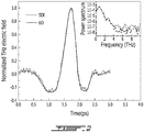
- the THz electric field measured using the present system and method is shown in Figure 2 .
- the EO sampling was done as well and is shown in dashed lines in Figure 2 .
- the corresponding spectrum is shown as an inset of Figure 2 .
- the signal to noise of the SDI appears to be lower than the EO sampling, but it can be improved using a low readout noise camera of the spectrometer 38.
- the optical probe beam was focused at the detection crystal 34 in a line. This line was imaged back on the 2D CCD camera of the spectrometer 38 along the vertical direction i.e. perpendicular to the diffraction plane of the grating in the spectrometer 38. This way the phase change or the OPD measured along vertical direction of the CCD camera gives the spatial profile of the THz signal.
- the reconstructed spatial profile of the THz beam is shown in Figure 3 .
- the full width at half maximum (FWHM) of the THz focal spot is measured to be 0.8 mm.
- Eo the THz peak electric field
- ⁇ 0 the free-space impedance (377 ⁇ )
- W is the THz energy
- ⁇ I is the intensity beam waist
- g(t) is the temporal shape of the THz electric field (with a peak value normalized to 1).
- the evaluated electric field is about 109 kV/cm.
- the scan length was limited to 3 ps due to the use of a glass plate 28 with thickness 300 ⁇ m (3 ps).
- This time frame can be increased by using a plate 28 of a larger thickness within the depth range of the SDI system. This decreases the signal-to-noise ratio (SNR) associated with the larger OPD between the two interfering signal [13].
- SNR signal-to-noise ratio
- a Mach-Zehnder interferometer configuration can be used.
- the above demonstrates a simple method and system, using spectral domain interferometry (SDI) to measure the change in the phase delay between the probe beam and the reference beam introduced by the EO crystal due to birefringence induced by the THz electric field. They allow to take long THz-TDS scans for increased spectral resolution without facing the limitation of over-rotation in the measurement.
- SDI spectral domain interferometry
- the present method and system allows measuring the THz electric field with good signal-to-noise ratio (SNR), which can further be improved by using a good quality CCD camera.
- SNR signal-to-noise ratio
- the present method and system allow reconstructing the spatial profile of the THz beam profile in a single shot.
- the present method and system not only allow measuring the intense THz electric field for spectroscopic purposes with good spectral resolution, but also simplify the required equipment by eliminating complicated components, such as lock-in amplifiers.
- the present method and system allow the use of thick detection crystals, by solving the problem of over-rotation for recently developed high power THz sources.
Landscapes
- Physics & Mathematics (AREA)
- Spectroscopy & Molecular Physics (AREA)
- General Physics & Mathematics (AREA)
- Investigating Or Analysing Materials By Optical Means (AREA)
Description
- The present invention relates to terahertz radiation. More specifically, the present invention is concerned with a method and a system for characterizing terahertz radiation.
- Terahertz (THz) radiation, with frequencies ranging from 0.1 to 10 THz, bridges the gap between radio frequencies and the infrared. This part of the electromagnetic spectrum remains the least explored, mainly due to technical difficulties involved in making efficient and compact THz sources and detectors. The lack of suitable technologies led to the THz band being called the "THz gap". This technological gap is rapidly diminishing with tremendous advances in optical technologies in the last two decades.
- THz sources and detectors have many important potential applications in the areas of spectroscopy, detection, and security [1-3]. For example, the low energy photons of the THz radiation can be safely used on humans for security purposes at airports, to detect weapons and explosives. THz radiation can also be used to study the vibrational modes of several biological and chemical molecules, since these modes have energies corresponding to THz photon energies. One example is the twisting and deformation of the double-helix structure in DNA. THz radiation is also suitable to study carrier transport and relaxation dynamics in condensed matter, such as bulk semiconductors, semiconductor quantum wells, carbon nanotubes, semiconductor quantum wells, and single-monolayer graphene sheets.
- Various methods such as photoconductive antenna [4], electro-optic (EO) sampling [5], and air-biased-coherent-detection (ABCD) [6] have been proposed and demonstrated in order to measure the spatial and temporal profile of the THz electric field.
- Among these, the electro-optic (EO) sampling method is widely used for THz time-domain spectroscopy (THz-TDS), due to the relatively straightforward physics involved and its wide bandwidth [7].
- In the electro-optic (EO) sampling method, a linearly polarized femtosecond laser pulse copropagates with a few picosecond THz pulse in an electro-optic (EO) crystal. The THz electric field induces birefringence in the crystal, which changes the polarization of the linearly co-propagating laser pulse. The change in the phase between the two polarization components of the probe beam, which is proportional to the THz electric field, is measured by using two cross polarizers before and after the detector crystal, and appears as a modulation in the intensity of the probe beam. The complete THz waveform is then reconstructed by scanning the probe pulse over the entire THz pulse.
- Several improvements over the EO sampling method have been proposed in the past to improve the detection of THz radiation. Such methods include a chirped-pulse or spectral-encoding method [8], a cross-correlation method [9], a two dimensional THz pulse characterization method with dual echelons [10], and a tilted wavefront detection method using prism [11].
- Since a major advantage of THz radiation is the possibility of coherent detection, in which information on both the electric field and phase can be measured simultaneously, THz radiation is a very important tool for spectroscopy and imaging applications [15]. In order to make use of advantageous features, such as wide bandwidth, of THz sources, a detection technique with (i) high spectral resolution and (ii) high sensitivity is needed.
- The spectral resolution (Δµ) obtained from a temporal scan of THz pulse depends on the length (T) of the scan (Δµ = 1/T). Therefore, to realize higher spectral resolution in THz-TDS, one needs to take waveform scans over longer time. In order to allow longer time scans, one needs to use thicker detection crystals. This is because part of the femtosecond probe beam is reflected from the two faces of the crystal. If a thin crystal is used, these internal reflections interfere with the main detected THz signal, which induces beating in the spectrum, thus distorting the measurement.
- High sensitivity is achieved with the use of a lock-in amplifier. In order to use the lock-in amplifier, first the THz signal is chopped at f/2 frequency where f is the repetition rate of the laser and then this signal is fed to the lock-in amplifier, which filters the THz signal, increasing its sensitivity.
- All methods up to now, which are based on EO sampling, use two cross polarizers, i.e. a first one placed before and a second one placed after, the detector crystal, to measure the polarization rotation of the probe beam, from which THz electric field is evaluated. However, when the polarization of the probe beam rotates more than 900, a reversal in the intensity modulation of the detection beam occurs, thus not allowing the correct measurement of the THz electric field and waveform [12]. This situation is referred to as "over-rotation". The birefringence introduced in the EO crystal is proportional to the THz electric field and the thickness of the crystal. Thus the issue of over-rotation increases with the increasing thickness of the crystal. One could in principle use thinner crystals to avoid over-rotation, but the use of thin crystal causes interference effects discussed above. With the recent advances in high power THz generation methods, over-rotation is becoming a major issue for THz-TDS.
- On the other hand, thinner crystals result in reduced THz signal and thus poor signal-to-noise ratio (SNR) of the measurement, due to a decrease in the interaction length. In a previously proposed ABCD method [6], although not limited by the problem of over-rotation, the use of a high voltage supply and lock-in amplifier makes it more complicated when compared to the EO sampling method.
- There is still a need for a THz electric field measurement method and system.
- More specifically, in accordance with the present invention, there is provided a spectral domain interferometry system for characterizing terahertz radiation according to
claim 4. - There is further provided a method for characterizing terahertz radiation comprising using spectral domain interferometry according to
claim 1. - Other objects, advantages and features of the present invention will become more apparent upon reading of the following non-restrictive description of specific embodiments thereof, given by way of example only with reference to the accompanying drawings.
- In the appended drawings:
-
Figure 1 shows a system according to an embodiment of an aspect of the present invention; -
Figure 2 shows THz electric field measurement with spectral domain interferometry (SDI) (solid line) and EO sampling (dashed line), the inset showing the corresponding spectrum of the THz field taken with the two methods respectively; and -
Figure 3 shows the spatial profile of the THz focal spot at the detector position according to an embodiment of an aspect of the present invention. - The present invention is illustrated in further details by the following non-limiting examples.
- In conventional spectral domain interferometry (SDI), a broadband light source of bandwidth Δλ centered around λ 0 is used to illuminate a reference surface and a sample surface in a Michelson interferometer scheme. The reflected signals from the reference and the sample surface, with intensities IR and IS respectively, are dispersed over a charged-coupled device (CCD) camera using a grating, to yield an interference signal that can be represented by:


- The instantaneous phase difference between the reference surface and the sample surface is determined using the following relation:

- Thus, change in the optical path difference (OPD) over the time can be tracked13 by monitoring the phase change given by relation (2). The phase measured with relation (2) is discontinuous due to the presence of arctangent but one can circumvent this issue by using conventional phase unwrapping methods14.
- A
system 10 according to an embodiment of an aspect of the present invention is shown inFigure 1 . - The input laser from a
laser 14 is split into twobeams first beam splitter 12. Thepump beam 18 is used to generate aTHz signal 22 using a tilted pulse front method in aTHz source 20 such as a LiNbO3 crystal for example. This THz source generates 0.3 µJ THz pulses, with bandwidth extending from 0.1 THz to 3 THz. - The
probe beam 16 is used for detecting the THz electric field. Asecond beam splitter 24 splits theprobe beam 16 into two equal parts. Areflected part 26 of the beam goes to aglass plate 28. The two surfaces of theglass plate 28 reflect about 4% of thisincident beam 26. Half of theprobe beam 16 that is reflected from theglass plate 28 is transmitted through thesecond beam splitter 24. The reflected signal from the glass plate consists of two pulses, i.e. a first pulse that is reflected from the front surface of the glass plate 28 (the right surface of theglass plate 28 inFigure 1 ), referred to hereinafter as the front pulse, and a second pulse reflected from the back surface of the glass plate 28 (the left surface of theglass plate 28 inFigure 1 ), referred to hereinafter as the back pulse. The delay between the two pulses is set by the thickness of theglass plate 28, which is selected so that the delay is longer than the duration of the THz pulse, thereby ensuring that the front pulse is not affected by the THz pulse. In case of aglass plate 28 having a refractive index of 1.5 and a thickness of 0.3 mm, the front pulse and the back pulse are separated by 3 ps. - The
THz beam 22 is focused into a 0.5mmthick detector crystal 34 such as aZnTe crystal 34 by an off-axis mirror 32. The front pulse and the back pulse propagate through a firstcylindrical lens 30 and a hole in the off-axis mirror 32, and are line focused onto thedetector crystal 34 at the same position as theTHz beam 22. The front pulse and the THz pulse are overlapped in space and time in thedetector crystal 34 while the back pulse and the THz pulse are overlapped in space only in thedetector crystal 34. - A second
cylindrical lens 36 is used to collimate the probe beam, which is then sent to aspectrometer 38, where the front pulse and the back pulse interfere. The first and secondcylindrical lenses - The
spectrometer 38 consists of a grating with 600 groves/mm, a cylindrical lens with focal length of f= 100 mm and a 2D CCD (Charge-Coupled Device) camera of 760 × 1024 pixels. At thespectrometer 38, interference fringes are caused by the interference between the front and back pulses. Since the different spectral components of the beam are separated after the diffraction grating of thespectrometer 38, the various spectral components of the probe pulse are not mode locked any more. This is why one can measure the interference pattern over the depth range of the SDI technique, determined by thespectrometer 38 used. For a Gaussian profiled spectrum, the depth range can be written as follows:
- Using the values of the parameters for the system illustrated in
Figure 1 , i.e. central wavelength λ 0 = 790nm, bandwidth Δλ = 40nm and number of pixels of the CCD camera of the spectrometer 38 N=1024 in relation (3), the theoretical depth range of the system is calculated to be 3.51 mm. This is the reason why the interference between the front and back probe pulses separated by the thickness of the glass plate 28 (3 ps) can easily be measured with SDI. Considering a change of 2π in the phase for one wavelength change in OPD, with the depth range of 3.51 mm, an OPD equal to 8898π at λ0 = 790nm can thus be measured. In contrast, in EO sampling one can measure a maximum phase change of π/2, which is approximately 18,000 times smaller than the OPD measurable with the present method. - To measure the complete THz pulse, an optical delay line is used to vary the time between the THz pulse and the optical pulse. The THz pulse is temporally matched with the optical back probe pulse. The delay between the front pulse and the back pulse is large enough (3 ps) so that the front pulse can pass through the
detector crystal 34 without seeing the THz electric field. The presence of the THz electric field changes the refractive index of thedetector crystal 34 via the Pockel effect, which affects the back pulse, which is temporally matched with the THz pulse, but not the front pulse, thus introducing a phase difference between the two optical probe pulses. This phase change between the two optical probe pulses is proportional to the THz electric field. Therefore, the THz pulse shape may be reconstructed by changing the delay stage. In the present SDI method, the change in the phase introduced by the change in refractive index of thedetector crystal 34 is measured, from which the THz electric field can be measured up to the depth range of the spectral domain method. - In order to reconstruct the THz signal, the data from the camera are numerically treated, involving some intermediate steps, as follows. First, the data from the camera of the
spectrometer 38 which were acquired in the wavelength space are rescaled in the wave vector (k)-space. These data were then Fourier transformed to obtain the frequency corresponding to the OPD between the two signals reflected from theglass plate 28. The phase between the two pulses reflected from theglass plate 28 are determined using relation (2) above. This phase is tracked over time by changing the delay between the THz signal and the probe signal. The phase waveform gives the waveform of the THz signal. - The THz electric field measured using the present system and method is shown in
Figure 2 . To make a comparison, the EO sampling was done as well and is shown in dashed lines inFigure 2 . The corresponding spectrum is shown as an inset ofFigure 2 . - The signal to noise of the SDI appears to be lower than the EO sampling, but it can be improved using a low readout noise camera of the
spectrometer 38. In the SDI detection method, the optical probe beam was focused at thedetection crystal 34 in a line. This line was imaged back on the 2D CCD camera of thespectrometer 38 along the vertical direction i.e. perpendicular to the diffraction plane of the grating in thespectrometer 38. This way the phase change or the OPD measured along vertical direction of the CCD camera gives the spatial profile of the THz signal. - The reconstructed spatial profile of the THz beam is shown in
Figure 3 . FromFigure 3 , the full width at half maximum (FWHM) of the THz focal spot is measured to be 0.8 mm. Knowing the energy and the temporal and the spatial shape of the THz pulse, the THz electric field is evaluated using following relation:
- In the system illustrated herein, the scan length was limited to 3 ps due to the use of a
glass plate 28 with thickness 300 µm (3 ps). This time frame can be increased by using aplate 28 of a larger thickness within the depth range of the SDI system. This decreases the signal-to-noise ratio (SNR) associated with the larger OPD between the two interfering signal [13]. However, in order to work around the zero OPD between the interfering signals where the signal-to-noise ratio (SNR) of the SDI is maximum, a Mach-Zehnder interferometer configuration can be used. - The above demonstrates a simple method and system, using spectral domain interferometry (SDI) to measure the change in the phase delay between the probe beam and the reference beam introduced by the EO crystal due to birefringence induced by the THz electric field. They allow to take long THz-TDS scans for increased spectral resolution without facing the limitation of over-rotation in the measurement.
- The present method and system allows measuring the THz electric field with good signal-to-noise ratio (SNR), which can further be improved by using a good quality CCD camera. The use of SDI in EO sampling eliminates the need of cross polarizers and thus overcomes the limitation of over-rotation for intense THz electric fields detections. Simple calculation suggest that a phase difference as high as 8898π at λ 0 = 790nm can be measured, which is approximately 18,000 times higher than the OPD measurable with the electro-optic sampling method (π/2).
- Moreover, the present method and system allow reconstructing the spatial profile of the THz beam profile in a single shot.
- The present method and system not only allow measuring the intense THz electric field for spectroscopic purposes with good spectral resolution, but also simplify the required equipment by eliminating complicated components, such as lock-in amplifiers.
- The present method and system allow the use of thick detection crystals, by solving the problem of over-rotation for recently developed high power THz sources.
- The scope of the claims should not be limited by the embodiments set forth in the examples, but should be given the broadest interpretation consistent with the description as a whole.
-
- 1. D. L. Woolard, W. R. Loerop, and M. S. Shur, Terahertz Sensing Technology (World Scientific, New Jersey, 2003).
- 2. D. Mittleman, Sensing with Terahertz Radiation (Springer-Verlag, Berlin, 2003).
- 3. A. G. Markelz, A. Roitberg, and E. J. Heilweil, "Pulsed terahertz spectroscopy of DNA, bovine serum albumin and collagen between 0.1 and 2.0 THz," Chemical Physics Letters 320, 42-48 (2000).
- 4. S. Kono, M. Tani, P. Gu, and K. Sakai, "Detection of up to 20 THz with a low-temperature-grown GaAs photoconductive antenna gated with 15 fs light pulses," Applied Physics Letters 77, 4104-4106 (2000).
- 5. X.-C. Zhang, J. A. Riordan, and F.-G. Sun, "Electro-optical and magneto-optical sensing apparatus and method for characterizing free-space electromagnetic radiation ", U. S. Patent, ed. (Rensselaer Polytechnic Institute USA, 2000).
- 6. X. Lu, and X. C. Zhang, "Balanced terahertz wave air-biased-coherent-detection," Applied Physics Letters 98, 151111-151113 (2011).
- 7. Q. Wu, and X. C. Zhang, "Free-space electro-optic sampling of terahertz beams," Applied Physics Letters 67, 3523-3525 (1995).
- 8. Z. Jiang, and X. C. Zhang, "Single-shot spatiotemporal terahertz field imaging," Opt. Lett. 23, 1114-1116 (1998).
- 9. S. P. Jamison, J. Shen, A. M. MacLeod, W. A. Gillespie, and D. A. Jaroszynski, "High-temporal-resolution, single-shot characterization of terahertz pulses," Opt. Lett. 28, 1710-1712 (2003).
- 10. K. Y. Kim, B. Yellampalle, A. J. Taylor, G. Rodriguez, and J. H. Glownia, "Single-shot terahertz pulse characterization via two-dimensional electro-optic imaging with dual echelons," Opt. Lett. 32, 1968-1970 (2007).
- 11. Y. Kawada, T. Yasuda, H. Takahashi, and S.-i. Aoshima, "Real-time measurement of temporal waveforms of a terahertz pulse using a probe pulse with a tilted pulse front," Opt. Lett. 33, 180-182 (2008).
- 12. J. Fletcher, "Distortion and uncertainty in chirped pulse THz," Opt. ).
- 13. T. Bajraszewski, M. Wojtkowski, M. Szkulmowski, A. Szkulmowska, R. Huber and A. Kowalczyk, " Improved spectral optical coherence tomography using optical frequency comb", Opt. Express 16 (6), 4163-4176 (2008).
- 14. J. Zhang, B. Rao, L. Yu and Z. Chen, "High-dynamic-range quantitaive phase imaging with spectral domain phase microscopy," Opt. Lett. 34, 3442-3444 (2009)
- 15.
D. H. Hurley, "Systems, methods, devices, and computer readable media for terahertz radiation detection," U.S. Patent application, Pub. No. US2011267599 (2011 ).
Claims (8)
- A method for characterizing terahertz radiation comprising using spectral domain interferometry to measure a change in the phase delay between a probe beam and a reference beam introduced by an electro-optic detector crystal due to birefringence induced by a terahertz electric field, characterized in that said method comprises:splitting an input broadband light beam into a pump pulse (18) and a probe pulse (16);passing the pump pulse (18) through a terahertz crystal (20) to generate a terahertz radiation (22);focusing the terahertz radiation (22) into a detector crystal (34) by an off-axis mirror (32);passing the probe pulse (16) through a glass plate (28) to generate a front pulse, reflecting from a front surface of the glass plate (28), and a back pulse, reflecting from a back surface of the glass plate (28), separated by an optical delay set by a thickness of the glass plate (28) and longer than a duration of the terahertz radiation (22);passing the front and back pulses through a hole in the off-axis mirror (32);overlapping the front pulse in time and space with the THz radiation (22) and the back pulse in space only with the THz radiation (22) in the detector crystal (34);sending the front and back pulses to a spectrometer (38); andobserving interferences between the front and back pulses.
- The method of claim 1, comprising a Fourier transform of the front and back pulses, thereby providing information on a relative phase difference between the front and back pulse.
- The method of claim 2, comprising tracking the relative phase difference between the front and back pulse over time.
- A spectral domain interferometry system (20) for characterizing terahertz radiation, comprising:a terahertz source (20), generating a terahertz pulse (22) from a pump beam (18);a glass plate (28) generating, from a probe beam (16), a front optical pulse beam and a back optical pulse beam separated by an optical delay longer than the duration of the THz pulse (22);an off-axis mirror (32);a first (30) and a second (36) cylindrical lenses;a detector crystal (34); anda spectrometer (38);characterized in that the terahertz pulse (22) is focused into the detector crystal (34) by said off-axis mirror (32); said two pulses propagate through the first cylindrical lens (30) and a hole in said off-axis mirror (32), and are line focused onto the detector crystal (34) at the same position as the terahertz pulse (22), the front pulse beam and the terahertz pulse (22) overlapping in space and time in the detector crystal (34) whereas the back pulse beam and the terahertz pulse (22) overlap in space only in the detector crystal (34), and the front and back pulses being sent to the spectrometer (38), said spectrometer (38) measuring changes in interference between the two pulses generated by said glass plate (28) due to birefringence induced by the terahertz electric field.
- The system (10) of claim 4, comprising:a broadband light source (14);a first beam splitter (12) splitting a beam from said broadband light source (14) into the probe beam (16) and the pump beam (18);a second beam splitter (24) splitting the probe beam (16) into a first optical beam and a second optical beam, said glass plate (28) reflecting the first optical beam as the front optical pulse beam and the back optical pulse beam;wherein the front pulse and the back pulse are sent to the spectrometer (38) where they interfere.
- The system (10) of any one of claims 4 and 5, wherein said terahertz source (20) is a LiNbO3 crystal; said glass plate (28) has a refractive index of 1.5 and a thickness of 0.3 mm, said two pulses being separated by an optical delay of 3 ps; and said detector crystal (34) is a 0.5mm thick ZnTe crystal.
- The system (10) of any one of claims 4 to 6, wherein said spectrometer (38) comprises a diffraction grating, a cylindrical lens and a CCD camera.
- The system (10) of any one of claims 4 to 7, further comprising an optical delay line used to vary the time between the THz pulse (22) and the probe beam (16).
Applications Claiming Priority (2)
| Application Number | Priority Date | Filing Date | Title |
|---|---|---|---|
| US201261678156P | 2012-08-01 | 2012-08-01 | |
| PCT/CA2013/050596 WO2014019091A1 (en) | 2012-08-01 | 2013-08-01 | Spectral-domain interferometric method and system for characterizing terahertz radiation |
Publications (3)
| Publication Number | Publication Date |
|---|---|
| EP2870442A1 EP2870442A1 (en) | 2015-05-13 |
| EP2870442A4 EP2870442A4 (en) | 2016-07-06 |
| EP2870442B1 true EP2870442B1 (en) | 2017-03-22 |
Family
ID=50027033
Family Applications (1)
| Application Number | Title | Priority Date | Filing Date |
|---|---|---|---|
| EP13826108.6A Not-in-force EP2870442B1 (en) | 2012-08-01 | 2013-08-01 | Spectral-domain interferometric method and system for characterizing terahertz radiation |
Country Status (4)
| Country | Link |
|---|---|
| US (1) | US9335213B2 (en) |
| EP (1) | EP2870442B1 (en) |
| CA (1) | CA2880828C (en) |
| WO (1) | WO2014019091A1 (en) |
Families Citing this family (13)
| Publication number | Priority date | Publication date | Assignee | Title |
|---|---|---|---|---|
| US10175111B2 (en) * | 2014-11-07 | 2019-01-08 | Institut National De La Recherche Scientifique | Method and apparatus for characterization of terahertz radiation |
| DE102015208796A1 (en) * | 2015-05-12 | 2016-11-17 | Technische Universität München | Static Fourier transform spectrometer |
| US11274969B2 (en) | 2016-07-20 | 2022-03-15 | Institut National De La Recherche Scientifique | Method and system for terahertz radiation detection and characterization |
| US11112454B2 (en) * | 2016-11-15 | 2021-09-07 | Ohio State Innovation Foundation | Antenna-coupled radio frequency (RF) probe with a replaceable tip |
| CN107014492B (en) * | 2017-05-26 | 2019-01-25 | 深圳大学 | A Self-Reference Terahertz Electro-Optical Sampling Spectral Interferometer and Measurement System |
| CN107167241A (en) * | 2017-07-07 | 2017-09-15 | 上海朗研光电科技有限公司 | Terahertz light spectrum imaging system and its fast scanning method |
| CN108387319B (en) * | 2018-01-03 | 2020-01-07 | 上海交通大学 | A single-shot broadband terahertz spectrum analyzer |
| CN108444913A (en) * | 2018-01-30 | 2018-08-24 | 中国科学院上海技术物理研究所 | Based on unit born of the same parents' solid phase grating and mutually with reference to the THz spectrometers of technology |
| CN111750990B (en) * | 2020-08-17 | 2025-04-04 | 江苏程泉智能装备有限公司 | Time-resolved spectrometer based on synchronization of electronics |
| CN112255190B (en) * | 2020-09-15 | 2023-05-02 | 华太极光光电技术有限公司 | Method, system, medium and device for filtering reflected pulse interference during THz-TDS test sample |
| CA3221522A1 (en) * | 2021-06-29 | 2023-01-05 | Junliang Dong | Single-shot multi-frame ultrafast terahertz imaging method and system |
| CN115235618B (en) * | 2022-09-08 | 2022-12-13 | 中国工程物理研究院激光聚变研究中心 | Single-frame measurement system and method for three-dimensional space-time distribution of ultrafast laser field |
| US12359972B2 (en) * | 2022-10-17 | 2025-07-15 | Lawrence Livermore National Security, Llc | Three phase spectral interferometry |
Family Cites Families (6)
| Publication number | Priority date | Publication date | Assignee | Title |
|---|---|---|---|---|
| CA2255762C (en) | 1996-05-31 | 2002-06-25 | Rensselaer Polytechnic Institute | Electro-optical and magneto-optical sensing apparatus and method for characterizing free-space electromagnetic radiation |
| US6479822B1 (en) | 2000-07-07 | 2002-11-12 | Massachusetts Institute Of Technology | System and Method for terahertz frequency measurements |
| US8759778B2 (en) * | 2007-09-27 | 2014-06-24 | Anis Rahman | Terahertz time domain and frequency domain spectroscopy |
| JP4280654B2 (en) * | 2004-02-17 | 2009-06-17 | アイシン精機株式会社 | Multi-channel terahertz spectrum measuring method and measuring apparatus |
| US8653462B2 (en) * | 2010-04-27 | 2014-02-18 | Rensselaer Polytechnic Institute | Methods and systems for detecting terahertz radiation by radiation enhanced emission of fluorescence |
| US20110267599A1 (en) | 2010-05-03 | 2011-11-03 | Battelle Energy Alliance, Llc | Systems, methods, devices, and computer readable media for terahertz radiation detection |
-
2013
- 2013-08-01 US US14/417,968 patent/US9335213B2/en not_active Expired - Fee Related
- 2013-08-01 WO PCT/CA2013/050596 patent/WO2014019091A1/en not_active Ceased
- 2013-08-01 CA CA2880828A patent/CA2880828C/en not_active Expired - Fee Related
- 2013-08-01 EP EP13826108.6A patent/EP2870442B1/en not_active Not-in-force
Non-Patent Citations (1)
| Title |
|---|
| None * |
Also Published As
| Publication number | Publication date |
|---|---|
| CA2880828C (en) | 2020-08-18 |
| WO2014019091A1 (en) | 2014-02-06 |
| US20150192467A1 (en) | 2015-07-09 |
| CA2880828A1 (en) | 2014-02-06 |
| EP2870442A1 (en) | 2015-05-13 |
| US9335213B2 (en) | 2016-05-10 |
| EP2870442A4 (en) | 2016-07-06 |
Similar Documents
| Publication | Publication Date | Title |
|---|---|---|
| US9335213B2 (en) | Spectral-domain interferometric method and system for characterizing terahertz radiation | |
| JP5711123B2 (en) | Fourier transform spectrometer with frequency comb light source | |
| US6504612B2 (en) | Electromagnetic wave analyzer | |
| Cousin et al. | Three-dimensional spatiotemporal pulse characterization with an acousto-optic pulse shaper and a Hartmann-Shack wavefront sensor | |
| EP3206014B1 (en) | Optical response measuring device and optical response measuring method | |
| Sharma et al. | Terahertz detection using spectral<? A3B2 show [pmg: line-break justify=" yes"/]?> domain interferometry | |
| JP5213167B2 (en) | Terahertz measurement device, time waveform acquisition method, and inspection device | |
| Weigel et al. | Ultra-rapid electro-optic sampling of octave-spanning mid-infrared waveforms | |
| Ito et al. | Single-beam phase-modulated stimulated Raman scattering microscopy with spectrally focused detection | |
| US10175111B2 (en) | Method and apparatus for characterization of terahertz radiation | |
| Ushakov et al. | Broadband in-line terahertz 2D imaging: comparative study with time-of-flight, cross-correlation, and Fourier transform data processing | |
| JPWO2006085403A1 (en) | Real-time terahertz tomography equipment and spectroscopic imaging equipment | |
| Couture et al. | Performance analysis of tabletop single-pulse terahertz detection at rates up to 1.1 MHz | |
| JP5510851B2 (en) | Terahertz measurement method | |
| Zhai et al. | Time-resolved single-shot terahertz time-domain spectroscopy for ultrafast irreversible processes | |
| Zaytsev et al. | A method of studying spectral optical characteristics of a homogeneous medium by means of terahertz time-domain spectroscopy | |
| US20110267599A1 (en) | Systems, methods, devices, and computer readable media for terahertz radiation detection | |
| Roberts et al. | A fast-scanning Fourier transform 2D IR interferometer | |
| US10203248B2 (en) | Electro-optic terahertz detector | |
| Ibrahim et al. | Terahertz detection based on spectral-domain interferometry using Mach-Zehnder interferometer | |
| Gorodetsky et al. | THz pulse time-domain holography | |
| Li et al. | Non-scanning systems for far-infrared radiation detection from laser-induced plasmas | |
| Lo et al. | Pulsed terahertz bi-directional reflection distribution function (BRDF) measurements of materials and obscurants | |
| Lu et al. | High-time-resolution and high-contrast spatiotemporal vortex measurement technology | |
| August et al. | Compressive Fourier Domain Optical Coherence Tomography |
Legal Events
| Date | Code | Title | Description |
|---|---|---|---|
| PUAI | Public reference made under article 153(3) epc to a published international application that has entered the european phase |
Free format text: ORIGINAL CODE: 0009012 |
|
| 17P | Request for examination filed |
Effective date: 20150129 |
|
| AK | Designated contracting states |
Kind code of ref document: A1 Designated state(s): AL AT BE BG CH CY CZ DE DK EE ES FI FR GB GR HR HU IE IS IT LI LT LU LV MC MK MT NL NO PL PT RO RS SE SI SK SM TR |
|
| AX | Request for extension of the european patent |
Extension state: BA ME |
|
| RIN1 | Information on inventor provided before grant (corrected) |
Inventor name: SHARMA, GARGI Inventor name: SINGH, KANWARPAL Inventor name: OZAKI, TSUNEYUKI Inventor name: MORANDOTTI, ROBERTO |
|
| DAX | Request for extension of the european patent (deleted) | ||
| RA4 | Supplementary search report drawn up and despatched (corrected) |
Effective date: 20160606 |
|
| RIC1 | Information provided on ipc code assigned before grant |
Ipc: G01J 3/45 20060101AFI20160531BHEP Ipc: G01N 21/3586 20140101ALI20160531BHEP Ipc: G01J 11/00 20060101ALI20160531BHEP Ipc: G01J 3/10 20060101ALI20160531BHEP Ipc: G01J 3/453 20060101ALI20160531BHEP |
|
| GRAP | Despatch of communication of intention to grant a patent |
Free format text: ORIGINAL CODE: EPIDOSNIGR1 |
|
| INTG | Intention to grant announced |
Effective date: 20161013 |
|
| GRAS | Grant fee paid |
Free format text: ORIGINAL CODE: EPIDOSNIGR3 |
|
| GRAA | (expected) grant |
Free format text: ORIGINAL CODE: 0009210 |
|
| AK | Designated contracting states |
Kind code of ref document: B1 Designated state(s): AL AT BE BG CH CY CZ DE DK EE ES FI FR GB GR HR HU IE IS IT LI LT LU LV MC MK MT NL NO PL PT RO RS SE SI SK SM TR |
|
| REG | Reference to a national code |
Ref country code: GB Ref legal event code: FG4D |
|
| REG | Reference to a national code |
Ref country code: CH Ref legal event code: EP |
|
| REG | Reference to a national code |
Ref country code: AT Ref legal event code: REF Ref document number: 878257 Country of ref document: AT Kind code of ref document: T Effective date: 20170415 |
|
| REG | Reference to a national code |
Ref country code: IE Ref legal event code: FG4D |
|
| REG | Reference to a national code |
Ref country code: DE Ref legal event code: R096 Ref document number: 602013019006 Country of ref document: DE |
|
| REG | Reference to a national code |
Ref country code: NL Ref legal event code: MP Effective date: 20170322 |
|
| PG25 | Lapsed in a contracting state [announced via postgrant information from national office to epo] |
Ref country code: NO Free format text: LAPSE BECAUSE OF FAILURE TO SUBMIT A TRANSLATION OF THE DESCRIPTION OR TO PAY THE FEE WITHIN THE PRESCRIBED TIME-LIMIT Effective date: 20170622 Ref country code: HR Free format text: LAPSE BECAUSE OF FAILURE TO SUBMIT A TRANSLATION OF THE DESCRIPTION OR TO PAY THE FEE WITHIN THE PRESCRIBED TIME-LIMIT Effective date: 20170322 Ref country code: LT Free format text: LAPSE BECAUSE OF FAILURE TO SUBMIT A TRANSLATION OF THE DESCRIPTION OR TO PAY THE FEE WITHIN THE PRESCRIBED TIME-LIMIT Effective date: 20170322 Ref country code: GR Free format text: LAPSE BECAUSE OF FAILURE TO SUBMIT A TRANSLATION OF THE DESCRIPTION OR TO PAY THE FEE WITHIN THE PRESCRIBED TIME-LIMIT Effective date: 20170623 Ref country code: FI Free format text: LAPSE BECAUSE OF FAILURE TO SUBMIT A TRANSLATION OF THE DESCRIPTION OR TO PAY THE FEE WITHIN THE PRESCRIBED TIME-LIMIT Effective date: 20170322 |
|
| REG | Reference to a national code |
Ref country code: FR Ref legal event code: PLFP Year of fee payment: 5 |
|
| REG | Reference to a national code |
Ref country code: LT Ref legal event code: MG4D |
|
| REG | Reference to a national code |
Ref country code: AT Ref legal event code: MK05 Ref document number: 878257 Country of ref document: AT Kind code of ref document: T Effective date: 20170322 |
|
| PG25 | Lapsed in a contracting state [announced via postgrant information from national office to epo] |
Ref country code: RS Free format text: LAPSE BECAUSE OF FAILURE TO SUBMIT A TRANSLATION OF THE DESCRIPTION OR TO PAY THE FEE WITHIN THE PRESCRIBED TIME-LIMIT Effective date: 20170322 Ref country code: LV Free format text: LAPSE BECAUSE OF FAILURE TO SUBMIT A TRANSLATION OF THE DESCRIPTION OR TO PAY THE FEE WITHIN THE PRESCRIBED TIME-LIMIT Effective date: 20170322 Ref country code: SE Free format text: LAPSE BECAUSE OF FAILURE TO SUBMIT A TRANSLATION OF THE DESCRIPTION OR TO PAY THE FEE WITHIN THE PRESCRIBED TIME-LIMIT Effective date: 20170322 Ref country code: BG Free format text: LAPSE BECAUSE OF FAILURE TO SUBMIT A TRANSLATION OF THE DESCRIPTION OR TO PAY THE FEE WITHIN THE PRESCRIBED TIME-LIMIT Effective date: 20170622 |
|
| PG25 | Lapsed in a contracting state [announced via postgrant information from national office to epo] |
Ref country code: NL Free format text: LAPSE BECAUSE OF FAILURE TO SUBMIT A TRANSLATION OF THE DESCRIPTION OR TO PAY THE FEE WITHIN THE PRESCRIBED TIME-LIMIT Effective date: 20170322 |
|
| PG25 | Lapsed in a contracting state [announced via postgrant information from national office to epo] |
Ref country code: AT Free format text: LAPSE BECAUSE OF FAILURE TO SUBMIT A TRANSLATION OF THE DESCRIPTION OR TO PAY THE FEE WITHIN THE PRESCRIBED TIME-LIMIT Effective date: 20170322 Ref country code: CZ Free format text: LAPSE BECAUSE OF FAILURE TO SUBMIT A TRANSLATION OF THE DESCRIPTION OR TO PAY THE FEE WITHIN THE PRESCRIBED TIME-LIMIT Effective date: 20170322 Ref country code: ES Free format text: LAPSE BECAUSE OF FAILURE TO SUBMIT A TRANSLATION OF THE DESCRIPTION OR TO PAY THE FEE WITHIN THE PRESCRIBED TIME-LIMIT Effective date: 20170322 Ref country code: RO Free format text: LAPSE BECAUSE OF FAILURE TO SUBMIT A TRANSLATION OF THE DESCRIPTION OR TO PAY THE FEE WITHIN THE PRESCRIBED TIME-LIMIT Effective date: 20170322 Ref country code: SK Free format text: LAPSE BECAUSE OF FAILURE TO SUBMIT A TRANSLATION OF THE DESCRIPTION OR TO PAY THE FEE WITHIN THE PRESCRIBED TIME-LIMIT Effective date: 20170322 Ref country code: EE Free format text: LAPSE BECAUSE OF FAILURE TO SUBMIT A TRANSLATION OF THE DESCRIPTION OR TO PAY THE FEE WITHIN THE PRESCRIBED TIME-LIMIT Effective date: 20170322 Ref country code: IT Free format text: LAPSE BECAUSE OF FAILURE TO SUBMIT A TRANSLATION OF THE DESCRIPTION OR TO PAY THE FEE WITHIN THE PRESCRIBED TIME-LIMIT Effective date: 20170322 |
|
| PGFP | Annual fee paid to national office [announced via postgrant information from national office to epo] |
Ref country code: CH Payment date: 20170915 Year of fee payment: 5 Ref country code: GB Payment date: 20170914 Year of fee payment: 5 Ref country code: FR Payment date: 20170808 Year of fee payment: 5 Ref country code: DE Payment date: 20170911 Year of fee payment: 5 |
|
| PG25 | Lapsed in a contracting state [announced via postgrant information from national office to epo] |
Ref country code: PL Free format text: LAPSE BECAUSE OF FAILURE TO SUBMIT A TRANSLATION OF THE DESCRIPTION OR TO PAY THE FEE WITHIN THE PRESCRIBED TIME-LIMIT Effective date: 20170322 Ref country code: PT Free format text: LAPSE BECAUSE OF FAILURE TO SUBMIT A TRANSLATION OF THE DESCRIPTION OR TO PAY THE FEE WITHIN THE PRESCRIBED TIME-LIMIT Effective date: 20170724 Ref country code: IS Free format text: LAPSE BECAUSE OF FAILURE TO SUBMIT A TRANSLATION OF THE DESCRIPTION OR TO PAY THE FEE WITHIN THE PRESCRIBED TIME-LIMIT Effective date: 20170722 Ref country code: SM Free format text: LAPSE BECAUSE OF FAILURE TO SUBMIT A TRANSLATION OF THE DESCRIPTION OR TO PAY THE FEE WITHIN THE PRESCRIBED TIME-LIMIT Effective date: 20170322 |
|
| REG | Reference to a national code |
Ref country code: DE Ref legal event code: R097 Ref document number: 602013019006 Country of ref document: DE |
|
| PLBE | No opposition filed within time limit |
Free format text: ORIGINAL CODE: 0009261 |
|
| STAA | Information on the status of an ep patent application or granted ep patent |
Free format text: STATUS: NO OPPOSITION FILED WITHIN TIME LIMIT |
|
| PG25 | Lapsed in a contracting state [announced via postgrant information from national office to epo] |
Ref country code: DK Free format text: LAPSE BECAUSE OF FAILURE TO SUBMIT A TRANSLATION OF THE DESCRIPTION OR TO PAY THE FEE WITHIN THE PRESCRIBED TIME-LIMIT Effective date: 20170322 |
|
| 26N | No opposition filed |
Effective date: 20180102 |
|
| PG25 | Lapsed in a contracting state [announced via postgrant information from national office to epo] |
Ref country code: SI Free format text: LAPSE BECAUSE OF FAILURE TO SUBMIT A TRANSLATION OF THE DESCRIPTION OR TO PAY THE FEE WITHIN THE PRESCRIBED TIME-LIMIT Effective date: 20170322 |
|
| PG25 | Lapsed in a contracting state [announced via postgrant information from national office to epo] |
Ref country code: MC Free format text: LAPSE BECAUSE OF FAILURE TO SUBMIT A TRANSLATION OF THE DESCRIPTION OR TO PAY THE FEE WITHIN THE PRESCRIBED TIME-LIMIT Effective date: 20170322 |
|
| REG | Reference to a national code |
Ref country code: IE Ref legal event code: MM4A |
|
| REG | Reference to a national code |
Ref country code: BE Ref legal event code: MM Effective date: 20170831 |
|
| PG25 | Lapsed in a contracting state [announced via postgrant information from national office to epo] |
Ref country code: LU Free format text: LAPSE BECAUSE OF NON-PAYMENT OF DUE FEES Effective date: 20170801 |
|
| PG25 | Lapsed in a contracting state [announced via postgrant information from national office to epo] |
Ref country code: IE Free format text: LAPSE BECAUSE OF NON-PAYMENT OF DUE FEES Effective date: 20170801 |
|
| PG25 | Lapsed in a contracting state [announced via postgrant information from national office to epo] |
Ref country code: BE Free format text: LAPSE BECAUSE OF NON-PAYMENT OF DUE FEES Effective date: 20170831 |
|
| PG25 | Lapsed in a contracting state [announced via postgrant information from national office to epo] |
Ref country code: MT Free format text: LAPSE BECAUSE OF NON-PAYMENT OF DUE FEES Effective date: 20170801 |
|
| REG | Reference to a national code |
Ref country code: DE Ref legal event code: R119 Ref document number: 602013019006 Country of ref document: DE |
|
| REG | Reference to a national code |
Ref country code: CH Ref legal event code: PL |
|
| GBPC | Gb: european patent ceased through non-payment of renewal fee |
Effective date: 20180801 |
|
| PG25 | Lapsed in a contracting state [announced via postgrant information from national office to epo] |
Ref country code: LI Free format text: LAPSE BECAUSE OF NON-PAYMENT OF DUE FEES Effective date: 20180831 Ref country code: CH Free format text: LAPSE BECAUSE OF NON-PAYMENT OF DUE FEES Effective date: 20180831 |
|
| PG25 | Lapsed in a contracting state [announced via postgrant information from national office to epo] |
Ref country code: HU Free format text: LAPSE BECAUSE OF FAILURE TO SUBMIT A TRANSLATION OF THE DESCRIPTION OR TO PAY THE FEE WITHIN THE PRESCRIBED TIME-LIMIT; INVALID AB INITIO Effective date: 20130801 |
|
| PG25 | Lapsed in a contracting state [announced via postgrant information from national office to epo] |
Ref country code: DE Free format text: LAPSE BECAUSE OF NON-PAYMENT OF DUE FEES Effective date: 20190301 |
|
| PG25 | Lapsed in a contracting state [announced via postgrant information from national office to epo] |
Ref country code: FR Free format text: LAPSE BECAUSE OF NON-PAYMENT OF DUE FEES Effective date: 20180831 |
|
| PG25 | Lapsed in a contracting state [announced via postgrant information from national office to epo] |
Ref country code: CY Free format text: LAPSE BECAUSE OF FAILURE TO SUBMIT A TRANSLATION OF THE DESCRIPTION OR TO PAY THE FEE WITHIN THE PRESCRIBED TIME-LIMIT Effective date: 20170322 Ref country code: GB Free format text: LAPSE BECAUSE OF NON-PAYMENT OF DUE FEES Effective date: 20180801 |
|
| PG25 | Lapsed in a contracting state [announced via postgrant information from national office to epo] |
Ref country code: MK Free format text: LAPSE BECAUSE OF FAILURE TO SUBMIT A TRANSLATION OF THE DESCRIPTION OR TO PAY THE FEE WITHIN THE PRESCRIBED TIME-LIMIT Effective date: 20170322 |
|
| PG25 | Lapsed in a contracting state [announced via postgrant information from national office to epo] |
Ref country code: TR Free format text: LAPSE BECAUSE OF FAILURE TO SUBMIT A TRANSLATION OF THE DESCRIPTION OR TO PAY THE FEE WITHIN THE PRESCRIBED TIME-LIMIT Effective date: 20170322 |
|
| PG25 | Lapsed in a contracting state [announced via postgrant information from national office to epo] |
Ref country code: AL Free format text: LAPSE BECAUSE OF FAILURE TO SUBMIT A TRANSLATION OF THE DESCRIPTION OR TO PAY THE FEE WITHIN THE PRESCRIBED TIME-LIMIT Effective date: 20170322 |