EP2870028B1 - A shelf - Google Patents
A shelf Download PDFInfo
- Publication number
- EP2870028B1 EP2870028B1 EP12735491.8A EP12735491A EP2870028B1 EP 2870028 B1 EP2870028 B1 EP 2870028B1 EP 12735491 A EP12735491 A EP 12735491A EP 2870028 B1 EP2870028 B1 EP 2870028B1
- Authority
- EP
- European Patent Office
- Prior art keywords
- shelf
- side wall
- pair
- opposite sides
- base
- Prior art date
- Legal status (The legal status is an assumption and is not a legal conclusion. Google has not performed a legal analysis and makes no representation as to the accuracy of the status listed.)
- Active
Links
- 238000003466 welding Methods 0.000 claims description 8
- 239000000463 material Substances 0.000 claims description 7
- 230000002787 reinforcement Effects 0.000 claims description 6
- 229910000797 Ultra-high-strength steel Inorganic materials 0.000 claims description 3
- 229910052751 metal Inorganic materials 0.000 description 6
- 239000002184 metal Substances 0.000 description 6
- 229910000831 Steel Inorganic materials 0.000 description 2
- 239000010959 steel Substances 0.000 description 2
- 230000007704 transition Effects 0.000 description 2
- 239000004411 aluminium Substances 0.000 description 1
- 229910052782 aluminium Inorganic materials 0.000 description 1
- XAGFODPZIPBFFR-UHFFFAOYSA-N aluminium Chemical compound [Al] XAGFODPZIPBFFR-UHFFFAOYSA-N 0.000 description 1
- 238000005452 bending Methods 0.000 description 1
- 230000001419 dependent effect Effects 0.000 description 1
- 238000000034 method Methods 0.000 description 1
Images


Classifications
-
- B—PERFORMING OPERATIONS; TRANSPORTING
- B60—VEHICLES IN GENERAL
- B60R—VEHICLES, VEHICLE FITTINGS, OR VEHICLE PARTS, NOT OTHERWISE PROVIDED FOR
- B60R11/00—Arrangements for holding or mounting articles, not otherwise provided for
- B60R11/06—Arrangements for holding or mounting articles, not otherwise provided for for tools or spare parts
-
- B—PERFORMING OPERATIONS; TRANSPORTING
- B60—VEHICLES IN GENERAL
- B60P—VEHICLES ADAPTED FOR LOAD TRANSPORTATION OR TO TRANSPORT, TO CARRY, OR TO COMPRISE SPECIAL LOADS OR OBJECTS
- B60P3/00—Vehicles adapted to transport, to carry or to comprise special loads or objects
- B60P3/14—Vehicles adapted to transport, to carry or to comprise special loads or objects the object being a workshop for servicing, for maintenance, or for carrying workmen during work
-
- A—HUMAN NECESSITIES
- A47—FURNITURE; DOMESTIC ARTICLES OR APPLIANCES; COFFEE MILLS; SPICE MILLS; SUCTION CLEANERS IN GENERAL
- A47B—TABLES; DESKS; OFFICE FURNITURE; CABINETS; DRAWERS; GENERAL DETAILS OF FURNITURE
- A47B96/00—Details of cabinets, racks or shelf units not covered by a single one of groups A47B43/00 - A47B95/00; General details of furniture
- A47B96/02—Shelves
- A47B96/021—Structural features of shelf bases
-
- A—HUMAN NECESSITIES
- A47—FURNITURE; DOMESTIC ARTICLES OR APPLIANCES; COFFEE MILLS; SPICE MILLS; SUCTION CLEANERS IN GENERAL
- A47B—TABLES; DESKS; OFFICE FURNITURE; CABINETS; DRAWERS; GENERAL DETAILS OF FURNITURE
- A47B96/00—Details of cabinets, racks or shelf units not covered by a single one of groups A47B43/00 - A47B95/00; General details of furniture
- A47B96/02—Shelves
- A47B96/024—Shelves characterised by support bracket location means, e.g. fixing means between support bracket and shelf
Definitions
- said second wall portion is connected to said first wall portion by mechanical fasteners at said locations.
- said mechanical fasteners are rivets and/or screws.
- the channel 23 is not limited to have a rectangular shaped cross-section, it may have any suitable shape. It may for example be circular or semi-circular.
- a sub-portion 25 of the second wall portion 22 is extending essentially parallel to the first wall portion in a direction towards the base 11 and it is abutting the first wall portion 21.
- the second wall portion 22 is connected to the first wall portion 21 in the area of the sub-portion 25 of the second wall portion 22 by clinching the two metal parts together so that one kind of rivet 40 is formed.
- connections are arranged in this area along the longitudinal direction of the first wall.
- rivets, screws and nuts, or sheet metal screws could be used to connect the two wall portions 21, 22 together. They could also be spot welded or welded over a distance or over the whole length of the first side wall 13a.
- Fig. 4g shows the first side wall 13a, similar to Fig. 4f , with the second side portion 22 welded to the first portion 21, but mirror inverted.
- Fig. 10 shows the cross-section B-B with the base reinforcement 50 on one side.
- the base 11 continues into a base portion 51 (see also Fig. 9 ), which overlaps at least partly said base 11 on the underside in such a way that said base portion 51 and said base 11 forms a channel 53, i.e. a second channel, along the longitudinal direction of the first side wall 13a.
- the base portion 51 has a sub portion 54 which is abutting the underside of the base 11.
- the base portion 53 is at least in some positions at the area of the sub portion 54 connected to said base 11 along the longitudinal direction of the first side wall 13 so that the channel 53 is at least partly a closed channel 53 in the longitudinal direction of the first side wall 13a.
- the connection can be done in the same way as described for the first side wall 13a.
Description
- The present invention relates to a shelf for a shelf system in a service vehicle comprising a base for arranging articles thereon and a first side wall.
- Service vehicles are used for a wide range of areas and the cargo space may be equipped to suit a particular application. For instance, a service vehicle may be used for storage and transport of tools for different kinds of craftsmen. It is common practise to equip the cargo space of a service vehicle with for instance storage cabinets, tool holders, shelves or other module units.
- Within the vehicle industry it is always a desire to reduce the weight of a vehide and the interior within it. Normally, shelves like disclosed in
US20100052490 in service vehicles are made of relatively thick metal, such as aluminium or steel, in order to be able to carry a lot of weight. Thus, these shelves are often quite heavy and also expensive due to the amount of material. Hence, there is a need for an improved shelf adapted for cargo spaces of service vehicles, which preferably is of less weight, but at the same time should be able to carry the same amount of weight as a known shelf. - The object of the present invention is to provide a shelf that overcomes the above issues. According to a first aspect of the invention this is accomplished by a shelf for a shelf system in a service vehicle comprising a base for arranging articles thereon and a first side wall, wherein said first side wall comprises a first wall portion connected to the base and a second wall portion, wherein said first wall portion continues into said second wall portion and said second wall portion overlaps at least partly said first wall portion in such a way that said first and second wall portions form a channel along the longitudinal direction of the first side wall, and said second wall portion is at least in some locations connected to said first wall portion along the longitudinal direction of the first side wall so that said channel is at least partly a closed channel in the longitudinal direction of the first side wall. If a side wall has at least a partly closed channel-structure, it will make the side wall more stable, which will make the shelf more durable. For example if the base of the shelf is relatively thin, the base will tend to buckle at the place where a heavy article is arranged due to the heavy load and this deformation/force will also apply to the side wall which will tend to bend towards the centre of shelf. The closed channel-structure will prevent that the side wall deforms towards the centre of the shelf. This reinforced side wall makes it possible to use a thinner sheet metal for making the shelf. The shelf may then weigh less. For example, a shelf may be made by a high-strength steel, for example ultra high strength steel, and by having the shape on the side wall described above the sheet for making the shelf may, for example be 0,6 mm thick instead of 1.2 mm. The geometry of the side wall reinforces the material and makes it stronger.
- The shelf may be arrangable to a module system, module unit or a shelf system. These systems may be adapted to be used in a back space of a service vehicle.
- According to at least one exemplary embodiment said channel is arranged at the upper part of said first side wall.
- According to at least one exemplary embodiment a sub-portion of said second wall portion is extending essential parallel to said first wall portion in a direction towards the base and abutting said first wall portion, and said second wall portion is connected to said first wall portion in the area of said sub-portion of said second wall portion. A sub-portion gives an extra area where it is possible to create a connection between the first and the second wall portions.
- According to at least one exemplary embodiment said second wall portion is connected to said first wall portion by mechanical fasteners at said locations. According to at least one exemplary embodiment said mechanical fasteners are rivets and/or screws.
- According to at least one exemplary embodiment said second wall portion is connected to said first wall portion by welding or clinching. When using welding the parts can be connected to each other by spot welding or seam welding. By using clinching no extra fasteners are necessary. The two wall portions will form a kind of rivet by itself.
- According to at least one exemplary embodiment said channel has a rectangular cross-section. It may, however, have any suitable shape.
- According to at least one exemplary embodiment said first side wall has a longitudinal extension along the longitudinal direction of the shelf. If the shelf is a very long shelf, having a longitudinal direction, it is preferable that the reinforced wall has its extension along the longitudinal direction of the shelf since this side wall will easier collapse than a side wall which is arranged on a side which is perpendicular to the longitudinal direction of a shelf.
- According to at least one exemplary embodiment said shelf comprises four sides with a first pair of opposite sides and a second pair of opposite sides, wherein said first side wall is arranged on one of the sides of said first pair of opposite sides and a second side wall is arranged on the second side of said pair first pair of opposite sides and said second side wall has the same design as said first side wall.
- According to at least one exemplary embodiment said.shelf comprises four sides with a first pair of opposite sides and a second pair of opposite sides, wherein said first side wall is arranged on one of the sides of said first pair of opposite sides and a second side wall is arranged on the second side of said first pair of opposite sides and said second side wall has the same design as said first side wall but mirror inverted. By having a second side wall on the opposite side of the shelf, which has the same design as the first side wall but mirror inverted the shelf will have the same look from both sides. The shelf can then be mounted with either side wall showing towards the user, and the shelf system will always look the same.
- According to at least one exemplary embodiment said shelf comprises four sides with a first pair of opposite sides and a second pair of opposite sides, wherein said first side wall is arranged on one of the sides of said first pair of opposite sides and said base comprises a base reinforcement on the second side of said first pair of opposite sides, wherein said base continues into a base portion, said base portion overlaps at least partly said base in such a way that said base portion and said base forms a channel parallel to the longitudinal direction of said first side wall, and said base portion is at least in some locations connected to said base along the longitudinal direction of the first side wall so that said channel is at least partly a closed channel parallel to longitudinal direction of the first side wall. If one side of the shelf shall be open in order to make it easier to reach articles arranged therein the shelf is preferable reinforced this way. The reinforced base side will prevent the base to deform when a heavy article is arranged on the thin base. The base reinforcement may be on the underside of said base, then it will not be in the way. The base portion may be connected to the base in the same way as described above in regard to the first wall portion and the second wall portion, i.e. by rivets, screws, welding or clinching.
- According to at least one exemplary embodiment said second pair of opposite sides are arranged perpendicular to said first pair of opposite sides wherein a third side wall is arranged on one of the sides of said second pair of opposite sides and/or a fourth side wall is arranged on the other one of the sides of said second pair of opposite sides. By having a third and/or a fourth side wall the shelf gets sturdier. This, since each side wall reinforces the base of the shelf.
- According to at least one exemplary embodiment said shelf comprises four sides with a first pair of opposite sides and a second pair of opposite sides, wherein said first side wall is arranged on one of the sides of said first pair of opposite sides and a third side wall is arranged on one of the sides of said second pair of opposite sides and/or a fourth side wall is arranged on the other one of the sides of said second pair of opposite sides.
- According to at least one exemplary embodiment a corner clip is arranged to the first side wall and to the third and/or fourth side walls in order to connect the corner of the shelf. A corner clip connects two sidewalls together and reinforces the corner of the shelf.
- According to at least one exemplary embodiment said first side wall is connected to the third side wall and/or to the fourth side wall. The first side wall may be connected to the third side wall and/or the fourth side walls by spot welding, clinching etc.
- According to at least one exemplary embodiment said shelf is made of a high-strength material, for example ultra high strength steel. With these materials the Young's modulus (modulus of elasticity) is the limited factor, however the shelf is improved by the shape of the shelf i.e. the side wall/side walls of the shelf, with its partly closed channel and/or the base reinforcement discussed above.
- Generally, all terms used in the claims are to be interpreted according to their ordinary meaning in the technical field, unless explicitly defined otherwise herein. All references to "a/an/the [element, device, component, means, step, etc]" are to be interpreted openly as referring to at least one instance of said element, device, component, means, step, etc., unless explicitly stated otherwise. The steps of any method disclosed herein do not have to be performed in the exact order disclosed, unless explicitly stated.
- Other objectives, features and advantages of the present invention will appear from the following detailed disclosure, from the attached dependent claims as well as from the drawings.
- The above, as well as additional objects, features and advantages of the present invention, will be better understood through the following illustrative and non-limiting detailed description of preferred embodiments of the present invention, with reference to the appended drawings, where the same reference numerals will be used for similar elements, wherein:
-
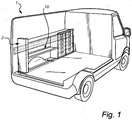
Fig. 1 discloses an open-up perspective view of a service vehicle comprising a module unit with a shelf according to the invention. -
Fig. 2 discloses a perspective view of a shelf according to a first embodiment of the invention. -
Fig. 3 discloses an exploded view ofFig. 2 with one side wall not bent. -
Figs. 4a, 4b, 4c, 4d, 4e, 4f and 4g disclose different variants of the cross-section A-A of the side wall inFig. 3 . -
Fig. 5 shows a part ofFig. 2 with one corner clip of a first embodiment exploded from the shelf. -
Fig. 6 shows a second embodiment of a corner clip. -
Fig. 7 shows a third embodiment of a corner clip. -
Fig. 8 shows a shelf similar toFig. 1 with the side walls according toFig. 4b with the corners connected to each other. -
Fig. 9 shows a shelf according to a second embodiment of the invention with only one side wall. -
Fig. 10 shows the cross-section B-B ofFig. 9 . - Currently preferred embodiments of the present invention will now be described in more detail, with reference to the accompanying drawings.
-
Fig. 1 shows a service vehicle 1 with amodule unit 2 comprising ashelf 10. The shelf is arranged in the module unit and connected to the module unit by fasteners, for example screws (not shown). -
Fig. 2 shows ashelf 10, which is extending in a longitudinal direction. The shelf comprises abase 11. Thebase 11 has foursides opposite sides 14 extending in the longitudinal direction of theshelf 10 and a second pair ofopposite sides 15 which are arranged perpendicular to the first pair ofopposite sides 14. On each side of said first pair ofopposite sides 14 is afirst side wall 13a and asecond side wall 13b arranged. On each side of said second pair ofopposite sides 15 is athird side wall 13c and afourth side wall 13d arranged. Theside walls side walls -
Fig. 3 shows theshelf 10 inFig. 2 but with thefourth side wall 13d unbent, i.e. when it is in the same plane as thebase 11 of theshelf 10 and with the corner clips 30 removed. The first and thesecond side walls shelf 10, have the same shape, however they are mirror inverted. Hence, only thefirst side wall 13a will hereinafter be described. Thefirst side wall 13a is so designed that it has a closed or at least a partly closed structure on its top portion, which creates achannel 23 in the longitudinal direction of theshelf 10. Thechannel 23 is created by theside wall 13a being bent into a suitable channel shape. Here thechannel 23 is exemplified by a rectangular shape, however it may take any suitable shape, for example some of the walls of the channel may be in an angle to the other walls which are larger or smaller than 90°. Thechannel 23 is in at least some locations in the longitudinal direction of the side wall a closed channel. Thechannel 23 is, as here exemplified, closed by usingrivets 40. Therivets 40 are arranged at equal distances from each other over the whole length of the shelf. Thechannel 23 is not limited to being closed by using rivets and they do not have to be arranged at equal distances. Further alternatives are discussed in regard toFig. 4a and Figs. 4f and 4g . -
Fig. 4a shows one exemplary embodiment of the cross-section of thefirst side wall 13a at cross-section A-A inFig. 3 . The cross-section shown inFig. 3 will be discussed in regard toFig. 4c . Thefirst side wall 13a inFig. 4a comprises afirst wall portion 21 and asecond wall portion 22. Thefirst wall portion 21 is connected to thebase 11 and it is extending perpendicular to thebase 11 via acurved portion 24. Thefirst wall portion 21 is not limited to be perpendicular to thebase 11 and to have acurved portion 24. It may be in an angle to thebase 11. Further thefirst wall portion 21 may be curved. - The
first wall portion 21 continues into thesecond wall portion 22. This can be done via atransition portion 28, which is exemplified as perpendicular to saidfirst wall portion 21. Thesecond wall portion 22 overlaps partly thefirst wall portion 21 on the outside ofshelf 10 in such a way that the first and thesecond wall portions loop 23, i.e. achannel 23 in the longitudinal direction of thefirst side wall 13a. Theloop 23 has a rectangular shape and is directed towards the outside of the shelf. That is, thechannel 23 has a rectangular shaped cross section. Hence, thefirst side wall 13a has a P-shaped top portion, which is protruding over the outer contour of the shelf. However, thechannel 23 is not limited to have a rectangular shaped cross-section, it may have any suitable shape. It may for example be circular or semi-circular. Asub-portion 25 of thesecond wall portion 22 is extending essentially parallel to the first wall portion in a direction towards thebase 11 and it is abutting thefirst wall portion 21. Thesecond wall portion 22 is connected to thefirst wall portion 21 in the area of thesub-portion 25 of thesecond wall portion 22 by clinching the two metal parts together so that one kind ofrivet 40 is formed. Several connections are arranged in this area along the longitudinal direction of the first wall. Alternatively rivets, screws and nuts, or sheet metal screws could be used to connect the twowall portions first side wall 13a. -
Fig. 4b shows a similar design of thefirst side wall 13a as the one described with regard toFig. 4a , with the differences that thesecond wall portion 22 is overlapping thefirst wall portion 21 on the inside of the self, so that the loop, i.e. thechannel 23 is on the inside of the shelf. That is the P-shaped top portion is pointing in the opposite direction, i.e. it has a mirror inverted P-shape to the one shown inFig. 4a . Thesecond wall portion 22 also has asimilar sub-portion 25 as described above, however arranged on the inside of the shelf and it can be connected to thefirst wall portion 21 in a similar way as described above. -
Fig. 4c shows the cross-section at A-A inFig. 3 of thefirst side wall 13a. The shape of the cross-section is almost the same as the one described in regard toFig. 4a , except that the whole overlappingsecond wall portion 22, including thesub-portion 25, and a sub-portion 29 of thefirst wall portion 21 which is being overlapped by thesecond wall portion 22 is projecting into the shelf. Hence, thefirst side wall 13a has a step shaped shape. This way the outer contour of the top portion of thefirst wall 13a follows the outer contour of the shelf, i.e. the P-shaped top portion is not protruding outside the outer contour of the shelf. That is thefirst wall portion 21. Thesecond wall portion 22 also has asimilar sub-portion 25 as described above and it can be connected to thefirst wall portion 21 in a similar way as described above. -
Fig. 4d shows another exemplary embodiment where theloop 23, i.e. thechannel 23 is centrally arranged over thefirst side wall 13a. Thefirst wall portion 21 has a step shapedtop portion 26 which continues into thesecond wall portion 22 via atransition portion 28 and thesecond wall portion 22 overlaps partly thefirst wall portion 21 in such a way that the step shapedtop portion 26 and thesecond wall portion 22 forms theloop 23, i.e. thechannel 23 in the longitudinal direction of thefirst side wall 13a. Theloop 23 has a rectangular shape and is directed towards both the outside and the inside of the shelf. The loop/channel 3 may however have a different shape than rectangular. Thesecond wall portion 22 also has asimilar sub-portion 25 as described above and it can be connected to thefirst wall portion 21 in a similar way as described above. - The
side wall 13a inFig. 4e has a similar shape as theside wall 13a inFig. 4a , except that theloop 23, i.e. the channel is not right on the top of thefirst wall 13a. The loop, i.e. thechannel 23 is positioned at a distance from the top. -
Fig. 4f shows thefirst side wall 13a, similar toFig. 4a but without a sub-portion (sub-portion 25 inFig. 4a ) on thesecond wall portion 22. Instead thesecond wall portion 22 is directly welded 27 to thefirst wall portion 21 and it ends perpendicular to thefirst wall portion 21. -
Fig. 4g shows thefirst side wall 13a, similar toFig. 4f , with thesecond side portion 22 welded to thefirst portion 21, but mirror inverted. - In
Fig. 2 and Fig. 3 both thefirst side wall 13a and thesecond side wall 13b are the same, however mirror inverted. They may, however, differ. For example thefirst side wall 13a may have a side wall as described in regard toFig. 4a and thesecond side wall 13b may have a side wall as described in regard to for exampleFig. 4d . - The third and the
fourth side walls Fig. 2 , which are extending perpendicular to the longitudinal direction of theshelf 10 are each a one portion wall which is here extending perpendicular to thebase 11 of the shelf. In the area where theend clip 30 shall be positioned, openings are provided which correspond to connecting parts of the corner clips. - In
Fig. 5 onecorner clip 30 is removed. Thecorner clip 30 has an approximately rectangular shape which is adapted to follow the outer contour of the shelf. It has a protruding connectingportion 36, which has an outer contour which follows the inner contour of theloop 23, i.e. the inner contour of thechannel 23, however it is slightly smaller so that it fits into the loop/channel 23. Theclip 30 has a larger rectangular 31 a and a smallershelf mounting opening 31 b. Thefourth sidewall 13d has on each respective side a larger rectangular 32a and a smallershelf mounting opening 32b which each will be in register with the larger rectangular 31 a and the smallershelf mounting opening 31 b of arespective corner clip 30 when theclip 30 is arranged to the corners of the shelf. These openings can be used to arrange the shelf to a side unit or to a module unit. Through theholes -
Fig. 6 shows another corner clip 30'. This is a sheet metal corner clip 30'. The corner clip 30' has an approximately rectangular shape which is adapted to follow the outer contour of the shelf. It has a protruding connecting portion 36' with atab 35 on the side facing the inner side of the shelf when arranged to the shelf. The protruding connecting portion 36'and itstab 35 will connect to thechannel 23. Thetab 35 will protrude into a hole (not shown) on the top of the channel. The clip 30' has a larger rectangular 31 a' and a smallershelf mounting opening 31b'. Thefourth sidewall 13d has on each respective side a larger rectangular 32a and a smallershelf mounting opening 32b, similar to the one shown inFig. 5 , which each will be in register with the larger rectangular 31 a' and the smallershelf mounting opening 31 b' of the corner clip 30' when the corner clip 30' is arranged to the corners of the shelf. These openings can be used to arrange the shelf to a side unit. The larger rectangularshelf mounting opening 31 a' has atongue 38 which is bent from the material in the clip towards the side facing the inner side of the shelf when arranged to the shelf. The corner clip 31 will be attached on the shelf by being pushed onto theside wall 13d from above, see arrow C. Thetongue 38 will pass through the larger rectangular mountingopening 32a and will overlap part of thethird side wall 13d on the inside of the shelf. Thetongue 38 also. has anopening 37 which will be in register with the smallershelf mounting opening 31 b when arranged in a correct position on theside wall 13d. -
Fig. 7 shows acorner clip 30" which will connect two corners to each other. Thecorner clip 30" comprises of twocorner clips 30 as described in regard toFig. 5 , and will hence not be further described, and they are connected by a connectingpart 37 which connects the twocorner clips 30 into asingle corner clip 30". Thecorner clip 30" is preferably made of plastic and made in one piece. Theconnected corner clip 30" andshelf 10 may also have theholes Fig. 5 but not shown inFig. 7 . If it has the holes the corner clip can be fastened to the shelf, for example by screws. -
Fig. 8 shows ashelf 10 without corner clips. Here thefirst side wall 13a and thefourth side wall 13d are connected to each other by aportion 50 of thefirst side wall 13a, which is being bent so that it overlaps thefourth side wall 13d and they are connected by, for example, spot welding. However they can be riveted or clinched or attached in any suitable way. All corners are connected this way. Alternatively, thefourth side wall 13d may comprise a portion which is bent so that it overlaps thefirst side wall 13a and they may then be attached together. -
Fig. 9 shows a second embodiment of theshelf 10. Theshelf 10 has a similar design to the shelf as described in regard toFig. 2 . It has afirst side wall 13a with itschannel 23, i.e. a first channel. However at thesecond side 12b of the base there is no second side wall arranged and no third and fourth side walls are shown, however they may be there and the corners can be connected to each other by, for examples, corner clips. Instead of a second side wall the shelf is open and comprises abase reinforcement 50 on thesecond side 12b. -
Fig. 10 shows the cross-section B-B with thebase reinforcement 50 on one side. Thebase 11 continues into a base portion 51 (see alsoFig. 9 ), which overlaps at least partly saidbase 11 on the underside in such a way that saidbase portion 51 and saidbase 11 forms achannel 53, i.e. a second channel, along the longitudinal direction of thefirst side wall 13a. Thebase portion 51 has asub portion 54 which is abutting the underside of thebase 11. Thebase portion 53 is at least in some positions at the area of thesub portion 54 connected to saidbase 11 along the longitudinal direction of the first side wall 13 so that thechannel 53 is at least partly aclosed channel 53 in the longitudinal direction of thefirst side wall 13a. The connection can be done in the same way as described for thefirst side wall 13a. - The
channel 53 has a rectangular cross-section. However it is not limited to be rectangular, it may take any suitable shape, for example any one of the ones described in regard to thechannel 23 of thefirst side wall 13a. Thebase portion 51 does not have to overlap on the underside of thebase 11, it may overlap on the upper side. - The shelves described in regard to the
Figs. 1-10 are made of sheet metal which are being roll formed or bent.
Claims (15)
- A shelf (10) for a shelf system in a service vehicle (1) comprising abase (11) for arranging articles thereon anda first side wall (13a), wherein
said first side wall (13a) comprisesa first wall portion (21) connected to the base (11) and a secondwall portion (22),
wherein said first wall portion (21) continues into said second wall portion (22) andsaid second wall portion (22) overlaps at least partly said first wall portion (21) in such a way that said first and second wall portion (21, 22) form a channel (23) along the longitudinal direction of the first side wall, andsaid second wall portion (22) is at least in some locations connected to said first wall portion (21) along the longitudinal direction of the first side wall (13a) so that said channel (23) is at least partly a closed channel (23) in the longitudinal direction of the first side wall (13a), characterized in that said shelf (10) comprises four sides (12a, 12b, 12c, 12d) with a first pair of opposite sides (14) and a second pair of opposite sides (15), wherein said first side wall (13a) is arranged on one (12a) of the sides (12a, 12b) of said first pair of opposite sides (14) and a third side wall (13c) is arranged on one of the sides of said second pair of opposite sides (15) and/or a fourth side wall (13d) is arranged on the other one of the sides of said second pair of opposite sides (15). - A shelf (10) according to claim 1, wherein said channel (23) is arranged at the upper part of said first side wall (13a).
- A shelf (10) according to any one of the preceding claims, wherein a sub-portion (25) of said second wall portion (22) is extending essentially parallel to said first wall portion (21) in a direction towards the base (11) and abutting said first wall portion (21), and said second wall portion (22) is connected to said first wall portion (21) in the area of said sub-portion (25) of said second wall portion (22).
- A shelf (10) according to any one of the preceding claims, wherein said second wall portion (22) is connected to said first wall portion (21) by mechanical fasteners at said locations.
- A shelf (10) according to claim 4, wherein said mechanical fasteners are rivets (25) and/or screws.
- A shelf (10) according to any one of claims 1 to 3, wherein said second wall portion (22) is connected to said first wall portion (21) by welding or clinching.
- A shelf (10) according to any one of the preceding claims, wherein said channel (23) has a rectangular cross-section.
- A shelf (10) according to any one of the preceding claims, wherein said first side wall (13a) has a longitudinal extension along the longitudinal direction of the shelf (10).
- A shelf (10) according to any one of the preceding claims, wherein said shelf (10) comprises four sides (12a, 12b, 12c, 12d) with a first pair of opposite sides (14) and a second pair of opposite sides (15), wherein said first side wall (13a) is arranged on one of the sides of said first pair of opposite sides (14) and a second side wall (13b) is arranged on the second side of said first pair of opposite sides (14) and said second side wall (13b) has the same design as said first side wall (13a).
- A shelf (10) according to claim 9 wherein said second side wall (13b) is mirror inverted to said first side wall (13a).
- A shelf (10) according to any one of claims 1 to 8, wherein said shelf (10) comprises four sides (12a, 12b, 12c, 12d) with a first pair of opposite sides (14) and a second pair of opposite sides (15), wherein said first side wall (13a) is arranged on one (12a) of the sides (12a, 12b) of said first pair of opposite sides (14) and said base (11) comprises a base reinforcement (50) on the second side of said pair first pair of opposite sides (14), wherein said base (11) continues into a base portion (51),
said base portion (51) overlaps at least partly said base (11) in such a way that said base portion (51) and said base (11) forms a channel (53) parallel to the longitudinal direction of said first side wall (13a), and
said base portion (51) is at least in some locations connected to said base (11) along the longitudinal direction of the first side wall (13a) so that said channel (53) is at least partly a closed channel parallel to longitudinal direction of the first side wall (13a). - A shelf according to claim 9 or 10 or 11, wherein said second pair of opposite sides (15) is arranged perpendicular to said first pair of opposite sides (14) wherein a third side wall (13c) is arranged on one of the sides of said second pair of opposite sides (15) and/or a fourth side wall (13d) is arranged on the other one of the sides of said second pair of opposite sides (15).
- A shelf according to claim 12, wherein a corner clip (30) is arranged to said first side wall (13a) and to at least one of said third or fourth side walls (13c, 13d) in order to connect the corner of the shelf.
- A shelf according to claim 12, wherein said first side wall (13a) is connected to said third side wall (13c) and/or to said fourth side wall (13d).
- A shelf according to any one of preceding claims, wherein said shelf is made of a high-strength material, for example ultra high strength steel.
Applications Claiming Priority (1)
| Application Number | Priority Date | Filing Date | Title |
|---|---|---|---|
| PCT/EP2012/062905 WO2014005620A1 (en) | 2012-07-03 | 2012-07-03 | A shelf |
Publications (2)
| Publication Number | Publication Date |
|---|---|
| EP2870028A1 EP2870028A1 (en) | 2015-05-13 |
| EP2870028B1 true EP2870028B1 (en) | 2017-02-01 |
Family
ID=47173710
Family Applications (1)
| Application Number | Title | Priority Date | Filing Date |
|---|---|---|---|
| EP12735491.8A Active EP2870028B1 (en) | 2012-07-03 | 2012-07-03 | A shelf |
Country Status (6)
| Country | Link |
|---|---|
| US (1) | US20150203053A1 (en) |
| EP (1) | EP2870028B1 (en) |
| JP (1) | JP6122109B2 (en) |
| DE (1) | DE202012008829U1 (en) |
| ES (1) | ES2622355T3 (en) |
| WO (1) | WO2014005620A1 (en) |
Families Citing this family (2)
| Publication number | Priority date | Publication date | Assignee | Title |
|---|---|---|---|---|
| US20150034580A1 (en) * | 2013-07-30 | 2015-02-05 | Henrik Hofvander | Modular Storage in Passenger Compartments |
| US11208048B2 (en) | 2019-07-11 | 2021-12-28 | Adrian Steel Company | Vehicle shelf system and method of use |
Family Cites Families (19)
| Publication number | Priority date | Publication date | Assignee | Title |
|---|---|---|---|---|
| US2210019A (en) * | 1934-08-15 | 1940-08-06 | Zalkind Philip | Three sided casing |
| US2374658A (en) * | 1941-03-12 | 1945-05-01 | Lyon Metal Products Inc | Shelf construction |
| US3100572A (en) * | 1960-10-14 | 1963-08-13 | Carl E Gingher | Adjustable supporting surfaces |
| US3081717A (en) * | 1962-01-10 | 1963-03-19 | Neiman Steel Equipment Co Inc | Boltless metal shelf construction with mounting clips |
| BE759735R (en) * | 1969-12-11 | 1971-05-17 | Rous Pierre | SHELVING |
| JPS537868Y2 (en) * | 1973-02-20 | 1978-02-28 | ||
| US3886698A (en) * | 1973-06-15 | 1975-06-03 | Hauserman Inc | Panel and structural units for wall assemblies |
| JPS5527470Y2 (en) * | 1973-11-21 | 1980-07-01 | ||
| JPS5754700Y2 (en) * | 1976-08-27 | 1982-11-26 | ||
| JPS6239731Y2 (en) * | 1980-01-21 | 1987-10-09 | ||
| DE8307469U1 (en) * | 1983-03-15 | 1983-10-13 | Bbp-Kunststoffwerk Marbach Baier & Co, 7142 Marbach | PLASTIC DRAWER FOR FURNITURE |
| SE454562B (en) * | 1986-09-23 | 1988-05-16 | Electrolux Const Ab | DEVICE FOR SHELVING SHEET |
| US5711435A (en) * | 1995-04-14 | 1998-01-27 | Peerless Home Products Inc. | Faucet display unit and method of forming shelf for use with same |
| DE10046947C2 (en) * | 2000-09-21 | 2002-11-28 | Tegometall International Ag Le | carrier |
| AU2003235443A1 (en) * | 2003-05-27 | 2005-01-21 | Nippon Steel Corporation | High strength thin steel sheet excellent in resistance to delayed fracture after forming and method for preparation thereof, and automobile parts requiring strength manufactured from high strength thin steel sheet |
| GB0622027D0 (en) * | 2006-11-06 | 2006-12-13 | Ford Global Tech Llc | A reinforcing member for a motor vehicle |
| SE530769C2 (en) * | 2006-12-22 | 2008-09-09 | Modul System Hh Ab | Modular system and use of such a system |
| US7731026B2 (en) * | 2008-09-04 | 2010-06-08 | Daws Manufacturing Co., Inc. | Insert for truck box |
| JP5540999B2 (en) * | 2010-08-25 | 2014-07-02 | 株式会社イトーキ | Side panel mounting device |
-
2012
- 2012-07-03 EP EP12735491.8A patent/EP2870028B1/en active Active
- 2012-07-03 US US14/411,016 patent/US20150203053A1/en not_active Abandoned
- 2012-07-03 JP JP2015518865A patent/JP6122109B2/en not_active Expired - Fee Related
- 2012-07-03 WO PCT/EP2012/062905 patent/WO2014005620A1/en active Application Filing
- 2012-07-03 ES ES12735491.8T patent/ES2622355T3/en active Active
- 2012-09-13 DE DE202012008829U patent/DE202012008829U1/en not_active Expired - Lifetime
Also Published As
| Publication number | Publication date |
|---|---|
| JP2015526330A (en) | 2015-09-10 |
| ES2622355T3 (en) | 2017-07-06 |
| DE202012008829U1 (en) | 2012-10-17 |
| JP6122109B2 (en) | 2017-04-26 |
| WO2014005620A1 (en) | 2014-01-09 |
| US20150203053A1 (en) | 2015-07-23 |
| EP2870028A1 (en) | 2015-05-13 |
Similar Documents
| Publication | Publication Date | Title |
|---|---|---|
| US7540085B2 (en) | Method of constructing a cargo body utilizing a plurality of panels | |
| US20130221702A1 (en) | Sidewall construction for trailer | |
| US7963588B2 (en) | Vehicle body lower structure | |
| EP2889187A2 (en) | Vehicle body impact absorption structure | |
| EP2448790B1 (en) | Bumper for a vehicle | |
| KR20080078915A (en) | Method for joining planar sheets and sheets therefor | |
| US20140015264A1 (en) | Vehicle end section structure | |
| US20170311721A1 (en) | Rack, load carrier and method of production | |
| JP6004910B2 (en) | Reinforcement structure for vehicle back door | |
| EP2870028B1 (en) | A shelf | |
| WO2016035501A1 (en) | Vehicle bumper beam | |
| JP2013220807A (en) | Vehicle body side structure | |
| US8857897B2 (en) | Light-load absorbing structure | |
| US9555838B2 (en) | Mixed material tunable rocker system | |
| EP3050731A1 (en) | Weather-strip-equipped vehicle body structure | |
| US20080258488A1 (en) | Load-carrying bed system and construction | |
| US11548570B2 (en) | Two panel cab back in unibody pick-up truck | |
| JP2008308133A (en) | Pillar structure of vehicle | |
| US20180229641A1 (en) | Logistic rail assembly for a composite panel | |
| JP4462994B2 (en) | Below the waist of the transport container | |
| US11104254B2 (en) | Console support structure | |
| US20180020832A1 (en) | Frame for a movable furniture part | |
| JP2005041598A (en) | Panel reinforcing member for elevator | |
| CN217456128U (en) | Outer panel connection structure and vehicle in luggage-boot lid | |
| JP6539053B2 (en) | Wagon type shelf device |
Legal Events
| Date | Code | Title | Description |
|---|---|---|---|
| PUAI | Public reference made under article 153(3) epc to a published international application that has entered the european phase |
Free format text: ORIGINAL CODE: 0009012 |
|
| 17P | Request for examination filed |
Effective date: 20150126 |
|
| AK | Designated contracting states |
Kind code of ref document: A1 Designated state(s): AL AT BE BG CH CY CZ DE DK EE ES FI FR GB GR HR HU IE IS IT LI LT LU LV MC MK MT NL NO PL PT RO RS SE SI SK SM TR |
|
| AX | Request for extension of the european patent |
Extension state: BA ME |
|
| DAX | Request for extension of the european patent (deleted) | ||
| GRAP | Despatch of communication of intention to grant a patent |
Free format text: ORIGINAL CODE: EPIDOSNIGR1 |
|
| INTG | Intention to grant announced |
Effective date: 20160817 |
|
| GRAS | Grant fee paid |
Free format text: ORIGINAL CODE: EPIDOSNIGR3 |
|
| GRAA | (expected) grant |
Free format text: ORIGINAL CODE: 0009210 |
|
| AK | Designated contracting states |
Kind code of ref document: B1 Designated state(s): AL AT BE BG CH CY CZ DE DK EE ES FI FR GB GR HR HU IE IS IT LI LT LU LV MC MK MT NL NO PL PT RO RS SE SI SK SM TR |
|
| REG | Reference to a national code |
Ref country code: GB Ref legal event code: FG4D |
|
| REG | Reference to a national code |
Ref country code: CH Ref legal event code: EP Ref country code: AT Ref legal event code: REF Ref document number: 865258 Country of ref document: AT Kind code of ref document: T Effective date: 20170215 |
|
| REG | Reference to a national code |
Ref country code: IE Ref legal event code: FG4D |
|
| REG | Reference to a national code |
Ref country code: DE Ref legal event code: R096 Ref document number: 602012028282 Country of ref document: DE |
|
| REG | Reference to a national code |
Ref country code: SE Ref legal event code: TRGR |
|
| REG | Reference to a national code |
Ref country code: NL Ref legal event code: FP |
|
| REG | Reference to a national code |
Ref country code: LT Ref legal event code: MG4D |
|
| REG | Reference to a national code |
Ref country code: AT Ref legal event code: MK05 Ref document number: 865258 Country of ref document: AT Kind code of ref document: T Effective date: 20170201 |
|
| REG | Reference to a national code |
Ref country code: FR Ref legal event code: PLFP Year of fee payment: 6 |
|
| REG | Reference to a national code |
Ref country code: ES Ref legal event code: FG2A Ref document number: 2622355 Country of ref document: ES Kind code of ref document: T3 Effective date: 20170706 |
|
| PG25 | Lapsed in a contracting state [announced via postgrant information from national office to epo] |
Ref country code: GR Free format text: LAPSE BECAUSE OF FAILURE TO SUBMIT A TRANSLATION OF THE DESCRIPTION OR TO PAY THE FEE WITHIN THE PRESCRIBED TIME-LIMIT Effective date: 20170502 Ref country code: HR Free format text: LAPSE BECAUSE OF FAILURE TO SUBMIT A TRANSLATION OF THE DESCRIPTION OR TO PAY THE FEE WITHIN THE PRESCRIBED TIME-LIMIT Effective date: 20170201 Ref country code: NO Free format text: LAPSE BECAUSE OF FAILURE TO SUBMIT A TRANSLATION OF THE DESCRIPTION OR TO PAY THE FEE WITHIN THE PRESCRIBED TIME-LIMIT Effective date: 20170501 Ref country code: FI Free format text: LAPSE BECAUSE OF FAILURE TO SUBMIT A TRANSLATION OF THE DESCRIPTION OR TO PAY THE FEE WITHIN THE PRESCRIBED TIME-LIMIT Effective date: 20170201 Ref country code: IS Free format text: LAPSE BECAUSE OF FAILURE TO SUBMIT A TRANSLATION OF THE DESCRIPTION OR TO PAY THE FEE WITHIN THE PRESCRIBED TIME-LIMIT Effective date: 20170601 Ref country code: LT Free format text: LAPSE BECAUSE OF FAILURE TO SUBMIT A TRANSLATION OF THE DESCRIPTION OR TO PAY THE FEE WITHIN THE PRESCRIBED TIME-LIMIT Effective date: 20170201 |
|
| PG25 | Lapsed in a contracting state [announced via postgrant information from national office to epo] |
Ref country code: AT Free format text: LAPSE BECAUSE OF FAILURE TO SUBMIT A TRANSLATION OF THE DESCRIPTION OR TO PAY THE FEE WITHIN THE PRESCRIBED TIME-LIMIT Effective date: 20170201 Ref country code: PL Free format text: LAPSE BECAUSE OF FAILURE TO SUBMIT A TRANSLATION OF THE DESCRIPTION OR TO PAY THE FEE WITHIN THE PRESCRIBED TIME-LIMIT Effective date: 20170201 Ref country code: PT Free format text: LAPSE BECAUSE OF FAILURE TO SUBMIT A TRANSLATION OF THE DESCRIPTION OR TO PAY THE FEE WITHIN THE PRESCRIBED TIME-LIMIT Effective date: 20170601 Ref country code: RS Free format text: LAPSE BECAUSE OF FAILURE TO SUBMIT A TRANSLATION OF THE DESCRIPTION OR TO PAY THE FEE WITHIN THE PRESCRIBED TIME-LIMIT Effective date: 20170201 Ref country code: LV Free format text: LAPSE BECAUSE OF FAILURE TO SUBMIT A TRANSLATION OF THE DESCRIPTION OR TO PAY THE FEE WITHIN THE PRESCRIBED TIME-LIMIT Effective date: 20170201 Ref country code: BG Free format text: LAPSE BECAUSE OF FAILURE TO SUBMIT A TRANSLATION OF THE DESCRIPTION OR TO PAY THE FEE WITHIN THE PRESCRIBED TIME-LIMIT Effective date: 20170501 |
|
| PG25 | Lapsed in a contracting state [announced via postgrant information from national office to epo] |
Ref country code: SK Free format text: LAPSE BECAUSE OF FAILURE TO SUBMIT A TRANSLATION OF THE DESCRIPTION OR TO PAY THE FEE WITHIN THE PRESCRIBED TIME-LIMIT Effective date: 20170201 Ref country code: CZ Free format text: LAPSE BECAUSE OF FAILURE TO SUBMIT A TRANSLATION OF THE DESCRIPTION OR TO PAY THE FEE WITHIN THE PRESCRIBED TIME-LIMIT Effective date: 20170201 Ref country code: EE Free format text: LAPSE BECAUSE OF FAILURE TO SUBMIT A TRANSLATION OF THE DESCRIPTION OR TO PAY THE FEE WITHIN THE PRESCRIBED TIME-LIMIT Effective date: 20170201 Ref country code: RO Free format text: LAPSE BECAUSE OF FAILURE TO SUBMIT A TRANSLATION OF THE DESCRIPTION OR TO PAY THE FEE WITHIN THE PRESCRIBED TIME-LIMIT Effective date: 20170201 |
|
| REG | Reference to a national code |
Ref country code: DE Ref legal event code: R097 Ref document number: 602012028282 Country of ref document: DE |
|
| PG25 | Lapsed in a contracting state [announced via postgrant information from national office to epo] |
Ref country code: SM Free format text: LAPSE BECAUSE OF FAILURE TO SUBMIT A TRANSLATION OF THE DESCRIPTION OR TO PAY THE FEE WITHIN THE PRESCRIBED TIME-LIMIT Effective date: 20170201 Ref country code: DK Free format text: LAPSE BECAUSE OF FAILURE TO SUBMIT A TRANSLATION OF THE DESCRIPTION OR TO PAY THE FEE WITHIN THE PRESCRIBED TIME-LIMIT Effective date: 20170201 |
|
| PLBE | No opposition filed within time limit |
Free format text: ORIGINAL CODE: 0009261 |
|
| STAA | Information on the status of an ep patent application or granted ep patent |
Free format text: STATUS: NO OPPOSITION FILED WITHIN TIME LIMIT |
|
| 26N | No opposition filed |
Effective date: 20171103 |
|
| PG25 | Lapsed in a contracting state [announced via postgrant information from national office to epo] |
Ref country code: SI Free format text: LAPSE BECAUSE OF FAILURE TO SUBMIT A TRANSLATION OF THE DESCRIPTION OR TO PAY THE FEE WITHIN THE PRESCRIBED TIME-LIMIT Effective date: 20170201 |
|
| REG | Reference to a national code |
Ref country code: CH Ref legal event code: PL |
|
| REG | Reference to a national code |
Ref country code: IE Ref legal event code: MM4A |
|
| PG25 | Lapsed in a contracting state [announced via postgrant information from national office to epo] |
Ref country code: LI Free format text: LAPSE BECAUSE OF NON-PAYMENT OF DUE FEES Effective date: 20170731 Ref country code: CH Free format text: LAPSE BECAUSE OF NON-PAYMENT OF DUE FEES Effective date: 20170731 Ref country code: IE Free format text: LAPSE BECAUSE OF NON-PAYMENT OF DUE FEES Effective date: 20170703 |
|
| REG | Reference to a national code |
Ref country code: BE Ref legal event code: MM Effective date: 20170731 |
|
| REG | Reference to a national code |
Ref country code: FR Ref legal event code: PLFP Year of fee payment: 7 |
|
| PG25 | Lapsed in a contracting state [announced via postgrant information from national office to epo] |
Ref country code: LU Free format text: LAPSE BECAUSE OF NON-PAYMENT OF DUE FEES Effective date: 20170703 |
|
| PG25 | Lapsed in a contracting state [announced via postgrant information from national office to epo] |
Ref country code: BE Free format text: LAPSE BECAUSE OF NON-PAYMENT OF DUE FEES Effective date: 20170731 |
|
| PG25 | Lapsed in a contracting state [announced via postgrant information from national office to epo] |
Ref country code: MT Free format text: LAPSE BECAUSE OF NON-PAYMENT OF DUE FEES Effective date: 20170703 |
|
| PG25 | Lapsed in a contracting state [announced via postgrant information from national office to epo] |
Ref country code: HU Free format text: LAPSE BECAUSE OF FAILURE TO SUBMIT A TRANSLATION OF THE DESCRIPTION OR TO PAY THE FEE WITHIN THE PRESCRIBED TIME-LIMIT; INVALID AB INITIO Effective date: 20120703 Ref country code: MC Free format text: LAPSE BECAUSE OF FAILURE TO SUBMIT A TRANSLATION OF THE DESCRIPTION OR TO PAY THE FEE WITHIN THE PRESCRIBED TIME-LIMIT Effective date: 20170201 |
|
| PG25 | Lapsed in a contracting state [announced via postgrant information from national office to epo] |
Ref country code: CY Free format text: LAPSE BECAUSE OF FAILURE TO SUBMIT A TRANSLATION OF THE DESCRIPTION OR TO PAY THE FEE WITHIN THE PRESCRIBED TIME-LIMIT Effective date: 20170201 |
|
| PG25 | Lapsed in a contracting state [announced via postgrant information from national office to epo] |
Ref country code: MK Free format text: LAPSE BECAUSE OF FAILURE TO SUBMIT A TRANSLATION OF THE DESCRIPTION OR TO PAY THE FEE WITHIN THE PRESCRIBED TIME-LIMIT Effective date: 20170201 |
|
| PG25 | Lapsed in a contracting state [announced via postgrant information from national office to epo] |
Ref country code: TR Free format text: LAPSE BECAUSE OF FAILURE TO SUBMIT A TRANSLATION OF THE DESCRIPTION OR TO PAY THE FEE WITHIN THE PRESCRIBED TIME-LIMIT Effective date: 20170201 |
|
| PG25 | Lapsed in a contracting state [announced via postgrant information from national office to epo] |
Ref country code: AL Free format text: LAPSE BECAUSE OF FAILURE TO SUBMIT A TRANSLATION OF THE DESCRIPTION OR TO PAY THE FEE WITHIN THE PRESCRIBED TIME-LIMIT Effective date: 20170201 |
|
| PGFP | Annual fee paid to national office [announced via postgrant information from national office to epo] |
Ref country code: NL Payment date: 20230621 Year of fee payment: 12 Ref country code: FR Payment date: 20230616 Year of fee payment: 12 |
|
| PGFP | Annual fee paid to national office [announced via postgrant information from national office to epo] |
Ref country code: SE Payment date: 20230616 Year of fee payment: 12 |
|
| PGFP | Annual fee paid to national office [announced via postgrant information from national office to epo] |
Ref country code: IT Payment date: 20230620 Year of fee payment: 12 Ref country code: GB Payment date: 20230615 Year of fee payment: 12 Ref country code: ES Payment date: 20230801 Year of fee payment: 12 |
|
| PGFP | Annual fee paid to national office [announced via postgrant information from national office to epo] |
Ref country code: DE Payment date: 20230619 Year of fee payment: 12 |