EP2869930B1 - Spout for producing a foam - Google Patents
Spout for producing a foam Download PDFInfo
- Publication number
- EP2869930B1 EP2869930B1 EP13812488.8A EP13812488A EP2869930B1 EP 2869930 B1 EP2869930 B1 EP 2869930B1 EP 13812488 A EP13812488 A EP 13812488A EP 2869930 B1 EP2869930 B1 EP 2869930B1
- Authority
- EP
- European Patent Office
- Prior art keywords
- spout
- screen
- screens
- pressurized mixture
- inlet
- Prior art date
- Legal status (The legal status is an assumption and is not a legal conclusion. Google has not performed a legal analysis and makes no representation as to the accuracy of the status listed.)
- Active
Links
- 239000006260 foam Substances 0.000 title claims description 51
- 239000000203 mixture Substances 0.000 claims description 131
- 239000007788 liquid Substances 0.000 claims description 44
- 235000013361 beverage Nutrition 0.000 claims description 15
- 238000012216 screening Methods 0.000 claims description 11
- 230000007246 mechanism Effects 0.000 claims description 8
- 239000002904 solvent Substances 0.000 claims description 7
- 230000001131 transforming effect Effects 0.000 claims description 4
- 238000005086 pumping Methods 0.000 claims description 2
- 239000007789 gas Substances 0.000 description 18
- 238000000034 method Methods 0.000 description 17
- 238000004140 cleaning Methods 0.000 description 13
- XLYOFNOQVPJJNP-UHFFFAOYSA-N water Substances O XLYOFNOQVPJJNP-UHFFFAOYSA-N 0.000 description 12
- 239000012530 fluid Substances 0.000 description 11
- 239000008267 milk Substances 0.000 description 9
- 238000013019 agitation Methods 0.000 description 8
- 235000013336 milk Nutrition 0.000 description 8
- 210000004080 milk Anatomy 0.000 description 8
- 244000299461 Theobroma cacao Species 0.000 description 7
- 235000015115 caffè latte Nutrition 0.000 description 7
- 235000013353 coffee beverage Nutrition 0.000 description 7
- 238000004519 manufacturing process Methods 0.000 description 7
- 239000011800 void material Substances 0.000 description 6
- 235000019219 chocolate Nutrition 0.000 description 5
- CURLTUGMZLYLDI-UHFFFAOYSA-N Carbon dioxide Chemical compound O=C=O CURLTUGMZLYLDI-UHFFFAOYSA-N 0.000 description 4
- 230000008901 benefit Effects 0.000 description 4
- 235000020289 caffè mocha Nutrition 0.000 description 4
- 235000015116 cappuccino Nutrition 0.000 description 4
- 230000014509 gene expression Effects 0.000 description 4
- 239000004615 ingredient Substances 0.000 description 4
- 239000000126 substance Substances 0.000 description 4
- 238000011144 upstream manufacturing Methods 0.000 description 4
- 239000006071 cream Substances 0.000 description 3
- 238000009826 distribution Methods 0.000 description 3
- 235000015114 espresso Nutrition 0.000 description 3
- 239000000463 material Substances 0.000 description 3
- 235000021481 specialty coffee Nutrition 0.000 description 3
- 235000009470 Theobroma cacao Nutrition 0.000 description 2
- 229910002092 carbon dioxide Inorganic materials 0.000 description 2
- 239000001569 carbon dioxide Substances 0.000 description 2
- 235000020140 chocolate milk drink Nutrition 0.000 description 2
- 235000020186 condensed milk Nutrition 0.000 description 2
- 230000001276 controlling effect Effects 0.000 description 2
- 238000013461 design Methods 0.000 description 2
- 235000020187 evaporated milk Nutrition 0.000 description 2
- 239000004744 fabric Substances 0.000 description 2
- 239000000796 flavoring agent Substances 0.000 description 2
- 235000019634 flavors Nutrition 0.000 description 2
- 238000011010 flushing procedure Methods 0.000 description 2
- 238000005187 foaming Methods 0.000 description 2
- 235000020278 hot chocolate Nutrition 0.000 description 2
- 235000020183 skimmed milk Nutrition 0.000 description 2
- 239000007787 solid Substances 0.000 description 2
- 239000004677 Nylon Substances 0.000 description 1
- 239000005862 Whey Substances 0.000 description 1
- 102000007544 Whey Proteins Human genes 0.000 description 1
- 108010046377 Whey Proteins Proteins 0.000 description 1
- 238000005054 agglomeration Methods 0.000 description 1
- 230000002776 aggregation Effects 0.000 description 1
- 239000000956 alloy Substances 0.000 description 1
- 229910045601 alloy Inorganic materials 0.000 description 1
- 229910052782 aluminium Inorganic materials 0.000 description 1
- XAGFODPZIPBFFR-UHFFFAOYSA-N aluminium Chemical compound [Al] XAGFODPZIPBFFR-UHFFFAOYSA-N 0.000 description 1
- 230000003190 augmentative effect Effects 0.000 description 1
- 208000027697 autoimmune lymphoproliferative syndrome due to CTLA4 haploinsuffiency Diseases 0.000 description 1
- 230000009286 beneficial effect Effects 0.000 description 1
- 235000015155 buttermilk Nutrition 0.000 description 1
- 239000005018 casein Substances 0.000 description 1
- BECPQYXYKAMYBN-UHFFFAOYSA-N casein, tech. Chemical compound NCCCCC(C(O)=O)N=C(O)C(CC(O)=O)N=C(O)C(CCC(O)=N)N=C(O)C(CC(C)C)N=C(O)C(CCC(O)=O)N=C(O)C(CC(O)=O)N=C(O)C(CCC(O)=O)N=C(O)C(C(C)O)N=C(O)C(CCC(O)=N)N=C(O)C(CCC(O)=N)N=C(O)C(CCC(O)=N)N=C(O)C(CCC(O)=O)N=C(O)C(CCC(O)=O)N=C(O)C(COP(O)(O)=O)N=C(O)C(CCC(O)=N)N=C(O)C(N)CC1=CC=CC=C1 BECPQYXYKAMYBN-UHFFFAOYSA-N 0.000 description 1
- 235000021240 caseins Nutrition 0.000 description 1
- 230000008859 change Effects 0.000 description 1
- 238000006243 chemical reaction Methods 0.000 description 1
- 239000003795 chemical substances by application Substances 0.000 description 1
- 235000020965 cold beverage Nutrition 0.000 description 1
- 239000002131 composite material Substances 0.000 description 1
- 238000005260 corrosion Methods 0.000 description 1
- 230000007797 corrosion Effects 0.000 description 1
- 230000001419 dependent effect Effects 0.000 description 1
- 230000035622 drinking Effects 0.000 description 1
- 238000001035 drying Methods 0.000 description 1
- 239000003995 emulsifying agent Substances 0.000 description 1
- 230000006870 function Effects 0.000 description 1
- 230000005484 gravity Effects 0.000 description 1
- 235000012171 hot beverage Nutrition 0.000 description 1
- 230000006872 improvement Effects 0.000 description 1
- 230000003993 interaction Effects 0.000 description 1
- 235000020191 long-life milk Nutrition 0.000 description 1
- 238000012423 maintenance Methods 0.000 description 1
- 229910052751 metal Inorganic materials 0.000 description 1
- 239000002184 metal Substances 0.000 description 1
- 150000002739 metals Chemical class 0.000 description 1
- 238000012986 modification Methods 0.000 description 1
- 230000004048 modification Effects 0.000 description 1
- 229920001778 nylon Polymers 0.000 description 1
- 239000000123 paper Substances 0.000 description 1
- 239000004033 plastic Substances 0.000 description 1
- 229920000728 polyester Polymers 0.000 description 1
- 229920000642 polymer Polymers 0.000 description 1
- 235000008476 powdered milk Nutrition 0.000 description 1
- 230000008569 process Effects 0.000 description 1
- 235000018102 proteins Nutrition 0.000 description 1
- 102000004169 proteins and genes Human genes 0.000 description 1
- 108090000623 proteins and genes Proteins 0.000 description 1
- 230000001105 regulatory effect Effects 0.000 description 1
- 238000009877 rendering Methods 0.000 description 1
- 230000008439 repair process Effects 0.000 description 1
- 230000004044 response Effects 0.000 description 1
- 235000013570 smoothie Nutrition 0.000 description 1
- 235000013322 soy milk Nutrition 0.000 description 1
- 239000010935 stainless steel Substances 0.000 description 1
- 229910001220 stainless steel Inorganic materials 0.000 description 1
- 238000003860 storage Methods 0.000 description 1
- 235000020357 syrup Nutrition 0.000 description 1
- 239000006188 syrup Substances 0.000 description 1
- 238000012360 testing method Methods 0.000 description 1
- 238000012546 transfer Methods 0.000 description 1
- 230000009466 transformation Effects 0.000 description 1
Images

Classifications
-
- A—HUMAN NECESSITIES
- A47—FURNITURE; DOMESTIC ARTICLES OR APPLIANCES; COFFEE MILLS; SPICE MILLS; SUCTION CLEANERS IN GENERAL
- A47J—KITCHEN EQUIPMENT; COFFEE MILLS; SPICE MILLS; APPARATUS FOR MAKING BEVERAGES
- A47J31/00—Apparatus for making beverages
- A47J31/44—Parts or details or accessories of beverage-making apparatus
- A47J31/4485—Nozzles dispensing heated and foamed milk, i.e. milk is sucked from a milk container, heated and foamed inside the device, and subsequently dispensed from the nozzle
-
- B—PERFORMING OPERATIONS; TRANSPORTING
- B01—PHYSICAL OR CHEMICAL PROCESSES OR APPARATUS IN GENERAL
- B01F—MIXING, e.g. DISSOLVING, EMULSIFYING OR DISPERSING
- B01F23/00—Mixing according to the phases to be mixed, e.g. dispersing or emulsifying
- B01F23/20—Mixing gases with liquids
- B01F23/23—Mixing gases with liquids by introducing gases into liquid media, e.g. for producing aerated liquids
- B01F23/235—Mixing gases with liquids by introducing gases into liquid media, e.g. for producing aerated liquids for making foam
-
- B—PERFORMING OPERATIONS; TRANSPORTING
- B01—PHYSICAL OR CHEMICAL PROCESSES OR APPARATUS IN GENERAL
- B01F—MIXING, e.g. DISSOLVING, EMULSIFYING OR DISPERSING
- B01F25/00—Flow mixers; Mixers for falling materials, e.g. solid particles
- B01F25/40—Static mixers
- B01F25/45—Mixers in which the materials to be mixed are pressed together through orifices or interstitial spaces, e.g. between beads
- B01F25/452—Mixers in which the materials to be mixed are pressed together through orifices or interstitial spaces, e.g. between beads characterised by elements provided with orifices or interstitial spaces
- B01F25/4521—Mixers in which the materials to be mixed are pressed together through orifices or interstitial spaces, e.g. between beads characterised by elements provided with orifices or interstitial spaces the components being pressed through orifices in elements, e.g. flat plates or cylinders, which obstruct the whole diameter of the tube
-
- B—PERFORMING OPERATIONS; TRANSPORTING
- B01—PHYSICAL OR CHEMICAL PROCESSES OR APPARATUS IN GENERAL
- B01F—MIXING, e.g. DISSOLVING, EMULSIFYING OR DISPERSING
- B01F25/00—Flow mixers; Mixers for falling materials, e.g. solid particles
- B01F25/40—Static mixers
- B01F25/45—Mixers in which the materials to be mixed are pressed together through orifices or interstitial spaces, e.g. between beads
- B01F25/452—Mixers in which the materials to be mixed are pressed together through orifices or interstitial spaces, e.g. between beads characterised by elements provided with orifices or interstitial spaces
- B01F25/4523—Mixers in which the materials to be mixed are pressed together through orifices or interstitial spaces, e.g. between beads characterised by elements provided with orifices or interstitial spaces the components being pressed through sieves, screens or meshes which obstruct the whole diameter of the tube
-
- B—PERFORMING OPERATIONS; TRANSPORTING
- B01—PHYSICAL OR CHEMICAL PROCESSES OR APPARATUS IN GENERAL
- B01F—MIXING, e.g. DISSOLVING, EMULSIFYING OR DISPERSING
- B01F33/00—Other mixers; Mixing plants; Combinations of mixers
- B01F33/80—Mixing plants; Combinations of mixers
- B01F33/81—Combinations of similar mixers, e.g. with rotary stirring devices in two or more receptacles
Definitions
- the present invention relates to a device, system, and method for producing a foam for use in the beverage-making industry, for example. More particularly, in one preferred use, the present invention relates to a spout, system and method for mechanically producing a "microfoam" from various types of liquid/air mixtures.
- Microfoams are known in the art.
- the term "microfoam” is generally understood to mean a mass of small bubbles.
- Foam substances characterized as “microfoam” generally have smaller bubbles than those of a regular foam, which gives the microfoam a liquid-like consistency.
- Microfoams are desirable in the beverage industry. Most of these beverage microfoams are usually produced by "frothing" the liquid with steam.
- microfoams In the specific field of preparing coffee beverages, creamier and shinier microfoams, made of milk, cream, chocolate, or any other ingredient, are very much in demand. The connoisseur appreciates, and often demands, the smooth, velvety taste of a microfoam-like substance, which sits afloat their beverage and is an enjoyable aspect of their coffee-drinking experience. Such microfoams can be made manually by a barista, who is generally an expert in the foaming art, and who can create homogeneously creamy and tasty foams that mix with the coffee, thereby making a latte, for example. This microfoam can also be manipulated to make "latte art” (i.e. designs out of the microfoam).
- the consistency of the microfoam to be produced this way can often vary. For example, for a classic "dry" cappuccino, the foam should be light and floats on top of the more dense espresso. The latte, however, requires a heavier "wetter” foam, that can mix with the coffee.
- foam is created when stem is introduced into a solution, such as milk.
- Milk can be foamed because of its low surface tension.
- Proteins in the milk such as casein and whey, help in the creation of foam because they attract and hold air from the steam, the air acting as an emulsifier.
- the air-to-milk ratio is a parameter which may determine foam density and viscosity and which may affect the ability to create several types of specialty coffee beverages.
- the size of the bubbles in the foam affect its texture, sometimes referred to in the field as its "feel" or "creaminess". The smaller that the bubbles can be made in the foam, the more creaminess the foam will have for the consumer of the beverage.
- Document EP 2 397 219 A2 discloses such device for foaming Soya milk.
- the outlet nozzle of the device may be provided with several screens having mesh size of between 0.3 to 0.4 mm.
- microfoam can be made in a variety of ways, the highest quality microfoams are currently achieved manually, whereby a barista or other operator uses a steam wand in conjunction with a professional espresso machine.
- this technique of producing a microfoam is barista-dependent, and the quality of the microfoam can change with the barista.
- Another disadvantage of such a system is that the creation of a steamed microfoam involves designing a complex and expensive water system, which must comply with numerous consumer safety standards.
- microfoams in colder speciality beverages as well, the most common of these being iced cappuccino and iced lattes.
- the microfoam created for these types of beverages is made from cold milk at around 4°C.
- Steam wands are not suitable for creating cold microfoams.
- microfoams work relatively well with microfoams made from homogenous liquids such as milk and cream, for example, but do not lend themselves to easily making microfoams from different, non-homogenous liquids such as the liquid obtained by insufficiently pre-mixing water with one or more condensed solutes, such as condensed milk.
- a spout for producing a foam from a pressurized mixture comprising a liquid containing gas bubbles comprising:
- a system for producing a foam comprising:
- the pressurized mixture is allowed to settle in a transitional volume before being passed through the screens.
- the transitional volume is located between the inlet and the plurality of screens, and receives the pressurized mixture from the inlet and conveys the pressurized mixture out through an output region.
- the transitional volume is fed by a mixing chamber.
- the mixing chamber receives the pressurized mixture from the inlet and conveys the pressurized mixture to the input of the transitional volume.
- a turbulence mechanism agitates or mixes the pressurized mixture within the mixing chamber, thereby ensuring a proper mixing of both homogenous and non-homogenous liquids in the pressurized mixture before the bubbles are screened by the plurality of screens.
- each screen there are between two and eight screens to screen the bubbles in the pressurized mixture to the desired size.
- the screen size and open area of each screen can also vary, depending on the particular microfoam desired and the pressurized mixture being used, among other factors.
- the screen spacing can also affect the microfoam produced.
- water or a cleaning fluid can be flushed through the system or spout after each use, thereby cleaning them.
- a pressurization unit can be used in combination with the system and spout to introduce either pressurized liquid or air into the system or spout.
- a spout in combination with a beverage-making machine for producing a foam.
- the term “foam” is understood to encompass foams and/or microfoams having bubbles of all sizes and consistencies. Therefore, the expressions “foam” and “microfoam”, and any other equivalent expressions known in the art will be used interchangeably.
- a spout 10 for producing a foam from a pressurized mixture according to one embodiment.
- the spout 10 can be any tube, conduit or other structure through which the pressurized mixture can be conveyed and altered.
- elements such as a "conduit”, “tube”, “pipe”, “chute”, “duct”, and the like which are capable of the functions ascribed herein are considered as "spouts" as used herein.
- the spout 10 can be incorporated into a beverage-making machine, such as a coffee machine, or it may be a separate component which is external to any such machine, such as when part of a nozzle which is connected to a machine via a bridging component.
- a beverage-making machine such as a coffee machine
- a separate component which is external to any such machine, such as when part of a nozzle which is connected to a machine via a bridging component.
- spout does not necessarily refer to the component ultimately delivering the foam to a cup or the like, but may be a component internal to the beverage-making machine.
- the spout 10 produces a foam or microfoam.
- foam By “produce”, it is understood that by passing the pressurized mixture through the spout 10, the pressurized mixture is altered such that a foam, preferably a microfoam, is generated from this passage of the pressurized mixture.
- the pressurized mixture consists of a liquid into which a gas is added, thus distributing gas bubbles throughout the liquid.
- gases can be used to produce the microfoam.
- a carbonated microfoam requires the use of carbon dioxide.
- air will be the gas used to describe the embodiments herein.
- foam means that the liquid and air are already somewhat mixed together, but may require additional agitation if certain liquids are used.
- pressurized can mean that the pressurized mixture of liquid/air bubbles travels through the spout 10 under a certain pressure, that is to say, under a force that is greater than the force resulting from gravity.
- the liquids to which air is added, thus producing the pressurized mixture can be broadly classified into two categories: homogenous and non-homogenous.
- Homogenous liquids can be those liquids which have a relatively uniform consistency. Prior to being transformed into a microfoam via the spout 10, homogenous liquids often only require that air be added to them.
- Some homogenous liquids include: partly skimmed milk, skim milk, UHT milk, chocolate milk, buttermilk, powdered milk (when sufficiently pre-mixed with water before being used according to the invention), chocolate and other types of sugar-based beverages, and artificial and natural flavour beverages.
- non-homogenous can refer to those liquids which do not have a relatively uniform consistency.
- these liquids are solutions consisting of a condensed solute being dissolved in water, which acts as a solvent.
- a condensed solute being dissolved in water, which acts as a solvent.
- this pressurized mixture may still require further mixing/agitation before it can be transformed into a microfoam.
- condensed solutes which can be used to produce these non-homogenous liquids include: evaporated milk, condensed milk, chocolate and other types of sugar-based syrups, and artificial and natural flavours.
- the spout 10 includes a spout enclosure 12 which has an inlet 14 and an outlet 16.
- the spout enclosure 12 gives structural support to the spout 10 and defines a fluid passage through which the pressurized mixture can travel.
- the spout enclosure 12 is generally cylindrical in shape, and thus resembles a tube.
- the shape of the spout enclosure 12 can vary.
- Figure 1B illustrates one such a varied shaped of the spout enclosure 12, where the spout enclosure 12 is exemplified as consisting of a narrower upper portion 12a joined with a wider lower portion 12b.
- the spout enclosure 12 may have a diameter which can vary depending on the size of the spout enclosure 12 that is needed for a particular application.
- One exemplary range of diameter values for the spout enclosure 12 is about 9.6 mm (0.375 inches) to about 25.4 mm (1 inch).
- the inlet 14 of the spout enclosure 12 receives the pressurized mixture from upstream of the spout 10.
- the inlet 14 receives the pressurized mixture from a manifold.
- the inlet 14 can be a volume, a void or a conduit, for example.
- the inlet 14 can be connected to a bespoke physical component such as a tube or a housing, which can be distinct from or integral to the spout enclosure 12, and which convey the pressurized mixture from upstream of the spout 10 to the inlet 14.
- This space and/or component receives the pressurized mixture so as to preferably convey it downstream within the spout enclosure 12.
- the outlet 16 conveys the microfoam (in contrast to the pressurized mixture) out of the spout enclosure 12 because the pressurized mixture has been converted into foam upstream of the outlet 16.
- the outlet 16 can be a void and it can be connected to a separate physical component.
- the outlet 16 is such a void, which can convey the microfoam out of the spout enclosure 12 to an outlet module for preparing the microfoam for delivery to a user's cup, or directly to the cup itself.
- the spout 10 also includes a plurality of screens 24.
- the purpose of the screens 24 is to reduce the size of the air bubbles in the pressurized mixture, as explained below. In some instances, the screens 24 may provide additional agitation or "frothing" to the pressurized mixture.
- the term "screen” as used herein refers to any perforated interface such as a surface, meshed wire, or cloth, which is mounted to a support. The screen can be used to separate large objects (i.e. large air bubbles) from smaller objects (i.e. smaller air bubbles), while allowing only these smaller objects to pass through the interface.
- each screen can be embodied by one of the devices known in the art such as a mesh, sieve, filter, or the like.
- the screens 24 are arranged in series or sequentially, which means that the outflow of the pressurized mixture from one screen 24 passes directly to the inflow of the subsequent or successive screen 24 downstream.
- Each screen 24 includes a plurality of holes, the disposition of which is referred to in the art as the screen's 24 "size” and its "open area".
- each screen 24 is made from a suitable material, such as stainless steel, aluminum, polyester, nylon, paper, cloth or the like, or a combination thereof.
- the screens 24 are separated from each other by a space designated herein as the screen spacing 26.
- the microfoam is produced by successively screening the pressurized mixture, which through the interaction of screens 24, screen sizes and open areas, and screen spacing 26, transforms the air bubbles in the pressurized mixture into foam bubbles which are smaller and generally more uniform in size than the air bubbles of the unscreened pressurized mixture.
- the screens 24 may be provided as part of a removable screen assembly 24a.
- the screen assembly 24a may for example include multiple screens 24 housed within a cartridge 24b.
- the cartridge 24b can be removed from the spout 10 for repair or replacement after a certain number of cycles, for example.
- the screen assembly 24a can be joined to, and removed from, the spout enclosure 12 just upstream of the outlet 16.
- a number of factors relating to the plurality of screens 24 can affect the microfoam produced. Some of these factors, such as the number of screens 24, the screen size and open area of the screens 24, and the screen spacing 26, are now discussed separately.
- the bubbles When the pressurized mixture passes through a given screen 24, the bubbles may be divided into smaller bubbles, thus creating an agglomeration of microbubbles.
- the bubbles since the bubbles are highly compressible, they may be compressed as pressure forces them through the holes of the screen 24. Having more screens 24 can facilitate the transformation of bubbles into microbubbles, thus obtaining an improved microfoam.
- the plurality of screens 24 may consist of between two and eight screens 24, although a greater number of screens 24 may also be used depending on the overall requirements. In one exemplary embodiment, a minimum of two screens 24 may be used thereby ensuring that a modicum of successive or "in series" screening occurs.
- a spout 10 equipped with six screens 24 may produce a relatively refined microfoam, but may have attendant clogging and cleaning issues.
- the final number of screens 24 can depend on the desired output for a given application or user. Furthermore, the number of screens 24 may not solely depend on issues of refinement, clogging, and cleaning, but may also depend on other factors such as, but not limited to, screen spacing 26, screen sizes and open areas, pumping capabilities, cleaning capabilities, liquid used, and the like. Therefore, the final determination of an optimal number of screens 24 for a given embodiment may require considering and integrating one or more of these factors.
- the disposition of the holes of the screens 24 can also affect the microfoam produced.
- two parameters may be chosen to define this disposition of holes in the screens 24: screen size and open area.
- the parameter "screen size” or “screen hole size” may refer to the diameter of a given hole in the screen 24 (i.e. where the screen 24 has circular holes), or may refer to the length and width of a given hole in the screen 24 (i.e. where the screen 24 has rectangular holes).
- the parameter "open area” is used in the context of the present disclosure to mean the percentage of the area of the screen 24 that is "open", or through which fluid may pass. The open area is calculated by dividing the total area occupied by the holes in the screen 24 by the total surface area of the screen 24.
- each screen 24 may vary, and can be measured in microns ( ⁇ m).
- the screen size is in the range of about 40 ⁇ m to about 300 ⁇ m.
- the open area is typically measured in percentage, and the open area of the screens 24 can vary between about 25% to about 50%. It will be readily understood that this range is given by way of example only and is not considered limitative to the scope of the invention.
- a "coarse" screen 24 would have a relatively large screen size and a relatively large open area, such as for example a screen 24 having a 300 ⁇ m screen size and an open area of 50%.
- a "fine" screen 24 may be considered to be one that has a relatively small screen size and a relatively small open area, such as for example a screen 24 having a 40 ⁇ m screen size and an open area of 25%.
- the screen size and open area of all the screens 24 are the same.
- the screen size and open area of each screen 24 can for example be in the order of about 80 ⁇ m x 80 ⁇ m and about 30%, respectively.
- the screen size and open area of each screen 24 can vary, and each screen 24 can be larger or more "coarse" than a successive screen 24.
- the first screen 24i can have a relatively large screen size of about 300 ⁇ m and an open area of about 50%.
- the second screen 24ii in series and downstream to the first screen 24i can be smaller or "finer", and may have a screen size of about 200 ⁇ m and an open area of about 30%.
- the second screen 24ii screens the bubbles of the pressurized mixture in the same way as the first screen 24i, thus producing even smaller bubbles than were produced by the first screen 24i.
- the third screen 24iii is successive to the second screen 24ii, and can be even finer than the second screen 24ii.
- the third screen 24iii can have a screen size of about 40 ⁇ m and an open area of about 25%.
- the third screen 24iii screens the bubbles in the same way as the first and second screens 24i,24ii.
- This general example illustrates how the microfoam may be produced as the pressurized mixture passes through the plurality of screens 24 arranged in series, each screen 24 reducing the size of the bubbles that pass through it until an acceptable bubble size is reached for the microfoam.
- the screen size of a given "mesh-type" screen 24 can vary throughout the mesh of the screen 24.
- Each of these differently sized mesh areas can be referred to as "mesh regions".
- Each mesh region, or at least one of them, can have a unique screen size and/or open area which differs from the screen size/open area of an adjacent mesh region.
- a first mesh region m1 can be defined by a circular band extending from the center of the mesh to a given radius, r1.
- the screen size and open area of mesh region m1 can be for example about 40 ⁇ m and 25%, respectively.
- An adjacent second mesh region m2 is another circular band extending from radius r1 to another radius r2.
- the screen size and open area of mesh region m2 can be for example about 200 ⁇ m and 40%, respectively.
- a third and final mesh region m3 is adjacent to mesh region m2, and is yet another circular band extending from radius r2 to an outer radius of the mesh r3.
- the screen size and open area of mesh region m3 can be for example about 300 ⁇ m and about 50%, respectively.
- Each mesh region going from m1 to m3 is progressively coarser.
- the plurality of mesh regions m1,m2,m3 may encourage an even distribution of bubbles across a given screen, which can improve the screening process.
- a subsequent screen 24 can have a similar distribution of mesh regions as described for m1, m2, and m3, but with screen sizes and open areas that are respectively finer than for mesh regions m1,m2,m3.
- the screen spacing 26 can also affect the microfoam produced by aiding in the distribution of bubbles and of pressurized mixture, thereby helping to produce a more uniform microfoam.
- the screen spacing 26 can be any space, volume, or void between consecutive screens 24. It is believed that if the screen spacing 26 is too small (i.e. the screens 24 are too close together), the quality of the microfoam produced may not be sufficient for many applications because the series of screens 24 essentially act as a single screen 24, loosing the beneficial effects of a succession of screens. Conversely, if the screen spacing 26 is too large (i.e.
- An exemplary range of screen spacing 26 values that may be used includes about 0.076 mm (a few thousandths of an inch) to about 6.35 mm (250 thousandths of an inch). In one exemplary embodiment, the screen spacing 26 between consecutive screens 24 can be about 1.52 mm (60 thousandths of an inch).
- the spout enclosure 12 further includes a transitional volume 18 between the inlet 14 and the screens 24.
- the transitional volume 18 is understood to be any space, void, cavity, and the like defined by any suitable structure (i.e. walls of the spout enclosure 12, separate physical component, etc.) which advantageously allows the pressurized mixture to settle and/or accumulate before being screened by the screens 24.
- the transitional volume 18 is similar in size and dimension to the screen spacing 26.
- the transitional volume 18 can be cylindrical in shape, and has an input region 18a where the pressurized mixture is received from the inlet 14.
- the transitional volume 18 also includes an output region 18b where the pressurized mixture is conveyed to the screens 24 downstream.
- the input region 18a is shown being narrower than the output region 18b, although the input region 18a may also be the same size or larger than the output region 18b.
- the spout enclosure 12 further includes a mixing chamber 20.
- the mixing chamber 20 is preferably cylindrical in shape, and allows for the agitation of the pressurized mixture passing therethrough.
- the mixing of pressurized mixture can be useful for pressurized mixtures made up of non-homogenous liquids. These non-homogenous liquids may require an additional mixing so as to create a pressurized mixture that is more uniformly mixed before being passed through the plurality of screens 24 so as to create the microfoam.
- a mixing chamber 20 can be used but is not usually necessary.
- the mixing chamber 20 is not necessarily a physically distinct chamber or housing; as with the inlet 14, outlet 16, and transitional volume 18, the mixing chamber can also consist of a void or space defined by the walls of the spout enclosure 12.
- the various bodies through which the pressurized mixture passes i.e. the inlet 14, the transitional volume 18, the mixing chamber 20, etc.
- turbulence may be generated and maintained, thereby ensuring that the pressurized mixture is properly mixed, or "homogenous", before passing through the screens 24.
- the mixing chamber 20 is positioned between the inlet 14 and the transitional volume 18. It receives the pressurized mixture from the inlet 14 and conveys the further agitated or mixed pressurized mixture to the input region 18a. Between the period at which the pressurized mixture is received from the inlet 14 and conveyed to the input region 18a, an agitation or mixing occurs. Preferably, this is accomplished by a turbulence mechanism 22, which imparts turbulence and/or agitation to the pressurized mixture.
- the turbulence mechanism 22 can be housed within the mixing chamber 20. Alternatively, the turbulence mechanism 22 can be an exterior component or stand-alone part that is functionally connected to the mixing chamber 20. The turbulence mechanism 22 also may allow for the maintenance of a desired liquid-to-air ratio.
- the turbulence mechanism 22 includes an inlet port 22a and an outlet port 22b of the mixing chamber 20.
- the inlet port 22a is positioned between the inlet 14 and the mixing chamber 20 (or the space 20a defined thereby).
- the inlet port 22a can be any aperture, hole, channel, or similar passage which allows for the constricted passage of the pressurized mixture from the inlet 14 to the mixing chamber 20.
- the inlet port 22a is substantially narrower than both the inlet 14 and the space 20a.
- the expression “substantially narrower” is understood to mean that the dimensions (i.e. width, circumference, diameter, cross-sectional area, etc.) of the inlet port 22a are significantly less than the dimensions of the inlet 14 and of the space 20a.
- the pressurized mixture would first pass through the inlet 14 and then be confined to a much narrower volume as it passed through the inlet port 22a, before finally exiting into the much larger space 20a.
- the inlet port 22a therefore restricts the flow of the pressurized mixture from the inlet 14 to mixing chamber 20, thereby increasing the pressure of the pressurized mixture entering the space 20a.
- the outlet port 22b is preferably similar to the inlet port 22a.
- the outlet port 22b is positioned between mixing chamber 20 and the input region 18a. As with the inlet port 22a, the outlet port 22b is also substantially narrower than both the space 20a and the input region 18a. Therefore, the outlet port 22b can also increase the pressure of the pressurized mixture. Preferably, in restricting the flow of the pressurized mixture out of the mixing chamber 20, the outlet port 22b also allows pressure to build up inside the mixing chamber 20.
- pressure inside the mixing chamber 20 can be increased in two ways: first, by augmenting the pressure of the pressurized mixture entering from the inlet port 22a, and second, by having the outlet port 22b restrict the flow of the pressurized mixture out of the mixing chamber 20.
- This increase in pressure caused by the inlet and outlet ports 22a,22b can significantly increase the turbulence in the mixing chamber, thereby agitating the pressurized mixture and causing further mixing.
- the spout 10 in combination with a beverage-making machine 40 to produce a foam, such as a microfoam.
- the beverage-making machine 40 can be a coffee machine, a hot chocolate machine, an espresso maker, or other machine capable of making a hot or cold beverage.
- the expression "in combination" as used to describe the relationship of the spout 10 with the beverage-making machine 40 can mean that the spout 10 can be exterior to the beverage-making machine 40 or a stand-alone component, and functionally connected thereto.
- the spout 10 can be incorporated into the beverage-making machine 40.
- the positioning and placement of the spout 10 in relation to the beverage-making machine 40 can depend upon many factors such as, but not limited to, aesthetic appearance, machine space constraints, spout 10 requirements, and other like factors.
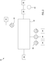
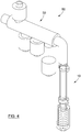
- Figure 4 exemplifies an embodiment of the system 50, which includes a manifold 30, and a spout 10 such as the one described above.
- the manifold 30 can be any chamber, conduit, receptacle, storage area, or other container which can receive multiple inputs and mix the elements thereby received, and which can then convey these mixed elements downstream of the manifold 30 via at least one outlet.
- the manifold 30 according to an embodiment of the invention includes a chamber 32 which can receive and mix the elements received therein.
- the chamber 32 has a plurality of intakes 34 which introduce into the chamber 32 pressurized air, and at least one of the following elements: a solute, a solvent or a homogenous liquid.
- the elements introduced into the chamber mix together under pressure, thereby generating a pressurized mixture.
- a solute need not be introduced into the chamber 32 at all.
- the pressurized mixture may be generated from introducing into the chamber 32 only air and a homogenous liquid, such as milk and the like.
- a solute such as evaporated milk may be dissolved in a solvent such as water to create a non-homogenous liquid.
- pressurized air can then be added to create the pressurized mixture.
- the pressurized mixture is then transferred via the at least one outtake 36 to the inlet of the spout. This transfer may occur through the use of a bridging component, such as a mixture conduit, which links the outtake 36 of the manifold 30 with the inlet of the spout.
- a mixture conduit include a plastic tube or hose.
- the spout of the system may be similar to embodiments of a spout described above. In some embodiments, however, the spout of the system may include only one screen to transform the air bubbles of the pressurized mixture into foam bubbles of a smaller and more uniform size. This configuration may be useful where less consistent foam is required and may reduce any related clogging and system pressure issues.
- Valves 38 can be used in combination with the intakes 34. These valves 38 may be check valves, one-way valves, or non-return valves for introducing into the chamber 32 the elements from the intakes 34 and for preventing their return. These valves 38 may also be control valves for controlling the flow of the elements into the chamber 32 and/or out of the outtake 36. Alternatively, the flow control of elements into the chamber 32 can be achieved with dedicated feeder systems or pumps, which when operated in conjunction with monitoring software and appropriate sensors, can control the exact amount of the elements introduced into the chamber 32, thereby helping to control and maintain a liquid-to-air ratio.
- the precise amount of air, a particular solvent, a particular solute or a particular homogeneous liquid through the intakes 34 can be controlled, it is possible to establish and maintain a liquid-to-air ratio (LAR) or a liquid-to-gas ratio (LGR) of the pressurized mixture.
- the LAR is a variable which can affect the quality of the microfoam produced.
- Other input variables can also affect the microfoam produced, examples of which include liquid and air temperature, liquid and air flow, stream velocity, and stream pulse.
- the manifold 30 can unite a precise dosage of air, solid ingredients, and liquids to create the pressurized mixture.
- the system can be cleaned after each use, after a predetermined number of uses, and/or in response to a user's input.
- the cleaning may be performed by flushing water or another cleaning fluid through the manifold 30 and then on through the spout and its outlet.
- air can then be flushed through the same components to dry them out.
- the water and air for flushing may be obtained from the plurality of the intakes 34 of the manifold 30 which introduce these elements.
- the water or cleaning fluid may be coupled to an external component such as a dedicated pump, which pumps the water and/or cleaning fluid through one of the intakes 34 of the manifold 30, and then on through the spout and out its outlet.
- Another one of the external components can be a pressurization unit 60.
- the pressurization unit 60 can include at least one mixture pump 62 which connects to one of the intakes 34 of the manifold 30.
- the mixture pump 62 can pump a liquid or air into the chamber 32 of the manifold 30, which provides pressure to the pressurized mixture.
- no mixture pump may be needed to pressurize the gas introduced into the chamber 32.
- a gas such as carbon dioxide could be created by a chemical reaction between two substances which is then introduced into the system.
- Pressurized air may also be introduced via gas/air canisters, which store gas/air under pressure. All techniques for introducing pressurized gas into the chamber 32 can help to control the LGR.
- Figures 3A and 3B illustrate step a), where the pressurized mixture is introduced into the spout enclosure 12.
- this involves introducing the pressurized mixture first through the inlet 14 and then through the inlet port 22a of the mixing chamber 20, if one is provided.
- the pressure of the pressurized mixture can increase as it goes through the inlet port 22a, thus causing agitation and turbulence in the pressurized mixture within the mixing chamber 20, as exemplified schematically in Figure 3B .
- the pressurized mixture preferably continues to flow through the spout 10, through the mixing chamber 20, and out through the outlet port 22b. As it flows through the outlet port 22b, the pressure of the pressurized mixture is increased which can cause further mixing, as exemplified schematically in Figure 3C . Once out of the outlet port 22b, the pressurized mixture can enter the input and output regions 18a,18b of the transitional volume 18, before entering the plurality of screens 24.
- Figures 3E to 3G illustrate step b), where the pressurized mixture is passed through a succession of screens 24, which transform the bubbles into bubbles of a smaller size.
- Figures 3E to 3F exemplify the decrease in bubble size of the pressurized mixture as it passes through each screen 24 in series.
- the pressurized mixture preferably becomes a microfoam, which exits the spout 10 as shown in Figure 3G .
- Figure 3H shows the spout 10 being cleaned by the cleaning fluid.
- a cleaning fluid such as water can be flushed through the spout 10 and out its outlet 16.
- a stream of pressurized air can then be flushed through the system/spout 10 after the water, thereby at least partially drying the spout 10.
- the LAR of the pressurized mixture may be controlled and/or determined by the manifold, for example.
- the spout 10, system, and corresponding parts are preferably made of substantially rigid materials, such as metals, alloys, hardened polymers, composite materials, and/or the like, depending on the particular applications for which the invention is intended for, and the different parameters in cause (temperature of fluids, corrosion, screen clogging, dimensions, etc.).
- the spout, system, and method for producing a microfoam according to described embodiments represent advantages over other methods and devices known in the art.
- the spout, system and method can allow for the controlled and automated production of a microfoam in a relatively quick manner, especially when compared to the steam wand technique known in the art.
- This production can be achieved mechanically and repeatedly by using the basic physics and chemical properties of the fluids and solid ingredients involved.
- Microfoams of different densities, viscosities, feels, and the like can be readily produced according to the invention by controlling such variables as the LAR, the number of screens, the screen size and open area, and the screen spacing.
- the production of a microfoam does not involve complex machinery such as the steam wand, which may reduce the need to perform costly testing so as to obtain regulatory approval.
- microfoam can be produced from both cold and hot liquids, with some liquid temperatures being as low as 4°C.
- both cold and hot microfoams can be created by the same spout, system, or method, an advantage that is difficultly achieved with known devices, if at all. This advantageously allows for the production of cold specialty coffee beverages such as iced cappuccinos and lattes.
- Another advantage provided is that the spout and system can be cleaned and then air-dried, quickly and automatically, thus reducing the intervention required of a human agent.
- the mixing chamber further allows non-homogenous liquids to be used in the pressurized mixture, thereby significantly increasing the number and types of microfoams that can be produced.
- chocolate is a basic specialty coffee ingredient utilized in beverages such as the mochaccino and cafe mocha. Additionally, many operators would like to offer hot cocoa and hot chocolate milk in their range of choices.
- the presence and use of the mixing chamber allows for the creation of a chocolate-based microfoam, thus inventing new beverages and expanding on the available selection.
- the use of the spout in combination with the beverage-making machine may allow for the control of the ratio of a microfoam produced to liquid in a cup.
- a drinking cup may be filled entirely with the microfoam, if desired.
- the machine can produce a cup filled half with a microfoam, and half with a beverage such as coffee, for example.
- hot and cold consumable products which can be used and produced by the spout and machine include, but are not limited to, cappuccino, cocoa, cafe latte, chocolate milk, chai latte, steamer, cafe mocha, smoothie, mochaccino, and whip cream.
Description
- The present invention relates to a device, system, and method for producing a foam for use in the beverage-making industry, for example. More particularly, in one preferred use, the present invention relates to a spout, system and method for mechanically producing a "microfoam" from various types of liquid/air mixtures.
- Microfoams are known in the art. The term "microfoam" is generally understood to mean a mass of small bubbles. Foam substances characterized as "microfoam" generally have smaller bubbles than those of a regular foam, which gives the microfoam a liquid-like consistency.
- Microfoams are desirable in the beverage industry. Most of these beverage microfoams are usually produced by "frothing" the liquid with steam.
- In the specific field of preparing coffee beverages, creamier and shinier microfoams, made of milk, cream, chocolate, or any other ingredient, are very much in demand. The connoisseur appreciates, and often demands, the smooth, velvety taste of a microfoam-like substance, which sits afloat their beverage and is an enjoyable aspect of their coffee-drinking experience. Such microfoams can be made manually by a barista, who is generally an expert in the foaming art, and who can create homogeneously creamy and tasty foams that mix with the coffee, thereby making a latte, for example. This microfoam can also be manipulated to make "latte art" (i.e. designs out of the microfoam). The consistency of the microfoam to be produced this way can often vary. For example, for a classic "dry" cappuccino, the foam should be light and floats on top of the more dense espresso. The latte, however, requires a heavier "wetter" foam, that can mix with the coffee.
- It is known that foam is created when stem is introduced into a solution, such as milk. Milk can be foamed because of its low surface tension. Proteins in the milk, such as casein and whey, help in the creation of foam because they attract and hold air from the steam, the air acting as an emulsifier. The air-to-milk ratio is a parameter which may determine foam density and viscosity and which may affect the ability to create several types of specialty coffee beverages. It is also known that the size of the bubbles in the foam affect its texture, sometimes referred to in the field as its "feel" or "creaminess". The smaller that the bubbles can be made in the foam, the more creaminess the foam will have for the consumer of the beverage.
-
Document EP 2 397 219 A2 discloses such device for foaming Soya milk. The outlet nozzle of the device may be provided with several screens having mesh size of between 0.3 to 0.4 mm. - Document
US 4 219 159 discloses a spout according to the preamble of claim 1. - Although a microfoam can be made in a variety of ways, the highest quality microfoams are currently achieved manually, whereby a barista or other operator uses a steam wand in conjunction with a professional espresso machine. However, this technique of producing a microfoam is barista-dependent, and the quality of the microfoam can change with the barista. Another disadvantage of such a system is that the creation of a steamed microfoam involves designing a complex and expensive water system, which must comply with numerous consumer safety standards.
- It is also desired to use microfoams in colder speciality beverages as well, the most common of these being iced cappuccino and iced lattes. Typically, the microfoam created for these types of beverages is made from cold milk at around 4°C. Steam wands are not suitable for creating cold microfoams. Furthermore, it is often time-consuming and not commercially feasible to make fresh cold microfoams on demand, especially in the busy environment of a modern-day coffee shop.
- An additional disadvantage of known techniques for making microfoams is that they work relatively well with microfoams made from homogenous liquids such as milk and cream, for example, but do not lend themselves to easily making microfoams from different, non-homogenous liquids such as the liquid obtained by insufficiently pre-mixing water with one or more condensed solutes, such as condensed milk.
- There remains a need for devices and/or methods for producing a foam having the consistency generally associated with a microfoam, which by virtue of their components, steps, and design, satisfy some of the above-mentioned needs and are thus an improvement over other related devices and/or methods known in the art.
- According to the invention, there is provided a spout according to claim 1 and a beverage-making machine according to claim 9.
- According to an aspect there is provided a spout for producing a foam from a pressurized mixture comprising a liquid containing gas bubbles, the spout comprising:
- a spout enclosure having an inlet receiving the pressurized mixture and an outlet conveying the foam out of the spout enclosure; and
- a plurality of screens disposed in series within the spout enclosure for successively screening the pressurized mixture, each screen having a plurality of holes therein and consecutive screens of said series having a screen spacing therebetween, the successive screening of the pressurized mixture progressively transforming the gas bubbles therein into foam bubbles of a smaller and generally uniform size, thereby producing the foam.
- According to another aspect, there is provided a system for producing a foam, the system comprising:
- a manifold comprising a chamber having a plurality of intakes, each intake introducing under pressure into the chamber gas, and at least one of a solute, a solvent and a liquid, thereby generating a pressurized mixture containing gas bubbles, the chamber also having at least one outtake conveying the pressurized mixture out of the manifold; and
- a spout for producing a foam from the pressurized mixture, the spout comprising:
- a spout enclosure having an inlet receiving the pressurized mixture from the at least one outtake of the manifold via a mixture conduit, and an outlet conveying the foam out of the spout enclosure; and
- at least one screen within the spout enclosure for screening the pressurized mixture, the at least one screen having a plurality of holes therein, the screening of the pressurized mixture transforming the gas bubbles therein into foam bubbles of a smaller and generally uniform size, thereby producing the foam.
- According to yet another aspect there is provided a method of producing a foam from a pressurized mixture comprising a liquid containing gas bubbles by using a spout, the spout comprising a spout enclosure and a plurality of screens disposed in series within the spout enclosure, consecutive screens of said series having a screen spacing therebetween, the method comprising the steps of :
- a) introducing the pressurized mixture into the spout enclosure; and
- b) passing the pressurized mixture successively through the plurality of screens, the successive screening of the pressurized mixture progressively transforming the gas bubbles therein into foam bubbles of a smaller and generally uniform size, thereby producing the foam.
- The pressurized mixture is allowed to settle in a transitional volume before being passed through the screens. The transitional volume is located between the inlet and the plurality of screens, and receives the pressurized mixture from the inlet and conveys the pressurized mixture out through an output region.
- The transitional volume is fed by a mixing chamber. The mixing chamber receives the pressurized mixture from the inlet and conveys the pressurized mixture to the input of the transitional volume. A turbulence mechanism agitates or mixes the pressurized mixture within the mixing chamber, thereby ensuring a proper mixing of both homogenous and non-homogenous liquids in the pressurized mixture before the bubbles are screened by the plurality of screens.
- Preferably, there are between two and eight screens to screen the bubbles in the pressurized mixture to the desired size. The screen size and open area of each screen can also vary, depending on the particular microfoam desired and the pressurized mixture being used, among other factors. The screen spacing can also affect the microfoam produced.
- According to another embodiment, water or a cleaning fluid can be flushed through the system or spout after each use, thereby cleaning them. Similarly, a pressurization unit can be used in combination with the system and spout to introduce either pressurized liquid or air into the system or spout.
- According to another aspect there is provided a use of a spout in combination with a beverage-making machine for producing a foam.
- The objects, advantages and other features of the present invention will become more apparent upon reading of the following non-restrictive description of preferred embodiments thereof, given for the purpose of exemplification only, with reference to the accompanying drawings.
-
-
Figure 1A is a perspective view of a spout for producing a foam, according to a preferred embodiment of the present invention. -
Figure 1B is a cross-sectional view of an interior of the spout ofFigure 1A taken along theline 1B-1B. -
Figure 2 is a schematic view of a manifold of a system for producing a foam, according to another embodiment of the present invention. -
Figures 3A to 3H are cross-sectional views of the interior of the spout ofFigure 1B showing the movement of the pressurized mixture and cleaning fluid through said spout. -
Figure 4 is a perspective view of a system for producing a foam, according to another embodiment of the present invention. - In the following description, the same numerical references refer to similar elements. Furthermore, for sake of simplicity and clarity, namely so as to not unduly burden the figures with several reference numbers, not all figures contain references to all the components and features of the present invention and references to some components and features may be found in only one figure, and components and features of the present invention illustrated in other figures can be easily inferred therefrom. The embodiments, geometrical configurations, materials mentioned and/or dimensions shown in the figures are preferred, for exemplification purposes only.
- Moreover, in the context of the description, the term "foam" is understood to encompass foams and/or microfoams having bubbles of all sizes and consistencies. Therefore, the expressions "foam" and "microfoam", and any other equivalent expressions known in the art will be used interchangeably.
- In addition, although the embodiments of the present invention as illustrated in the accompanying drawings comprise various components and although the described embodiments of the spout, system and method as shown consist of certain geometrical configurations as explained and illustrated herein, not all of these components and geometries are essential to the invention and thus should not be taken in their restrictive sense, i.e. should not be taken as to limit the scope of the present invention. It is to be understood, as also apparent to a person skilled in the art, that other suitable components and cooperations thereinbetween, as well as other suitable geometrical configurations may be used for the spout, system and corresponding parts, according to the present invention, as briefly explained and as can be easily inferred herefrom by a person skilled in the art, without departing from the scope of the invention as defined by the claims.
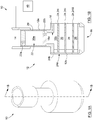
- Referring to
Figures 1A and 1B , there is shown aspout 10 for producing a foam from a pressurized mixture according to one embodiment. It is understood that thespout 10 can be any tube, conduit or other structure through which the pressurized mixture can be conveyed and altered. For this reason, elements such as a "conduit", "tube", "pipe", "chute", "duct", and the like which are capable of the functions ascribed herein are considered as "spouts" as used herein. Thespout 10 can be incorporated into a beverage-making machine, such as a coffee machine, or it may be a separate component which is external to any such machine, such as when part of a nozzle which is connected to a machine via a bridging component. One skilled in the art will therefore readily understand that the term "spout" does not necessarily refer to the component ultimately delivering the foam to a cup or the like, but may be a component internal to the beverage-making machine. - The
spout 10 produces a foam or microfoam. By "produce", it is understood that by passing the pressurized mixture through thespout 10, the pressurized mixture is altered such that a foam, preferably a microfoam, is generated from this passage of the pressurized mixture. The pressurized mixture consists of a liquid into which a gas is added, thus distributing gas bubbles throughout the liquid. Many different types of gases can be used to produce the microfoam. For example, a carbonated microfoam requires the use of carbon dioxide. However, for the purposes of clarity and succinctness, air will be the gas used to describe the embodiments herein. One skilled in the art will however understand that other embodiments may make the foam using a different gas without departing from the scope of the present invention. The term "mixture" means that the liquid and air are already somewhat mixed together, but may require additional agitation if certain liquids are used. The term "pressurized" can mean that the pressurized mixture of liquid/air bubbles travels through thespout 10 under a certain pressure, that is to say, under a force that is greater than the force resulting from gravity. - The liquids to which air is added, thus producing the pressurized mixture, can be broadly classified into two categories: homogenous and non-homogenous. Homogenous liquids can be those liquids which have a relatively uniform consistency. Prior to being transformed into a microfoam via the
spout 10, homogenous liquids often only require that air be added to them. Some homogenous liquids include: partly skimmed milk, skim milk, UHT milk, chocolate milk, buttermilk, powdered milk (when sufficiently pre-mixed with water before being used according to the invention), chocolate and other types of sugar-based beverages, and artificial and natural flavour beverages. The term "non-homogenous" can refer to those liquids which do not have a relatively uniform consistency. Typically, these liquids are solutions consisting of a condensed solute being dissolved in water, which acts as a solvent. When air is added to these non-homogenous liquids, thus generating a pressurized mixture, this pressurized mixture may still require further mixing/agitation before it can be transformed into a microfoam. Examples of condensed solutes which can be used to produce these non-homogenous liquids include: evaporated milk, condensed milk, chocolate and other types of sugar-based syrups, and artificial and natural flavours. - Referring more particularly to
Figure 1B , thespout 10 according to the illustrated embodiment includes aspout enclosure 12 which has aninlet 14 and anoutlet 16. Thespout enclosure 12 gives structural support to thespout 10 and defines a fluid passage through which the pressurized mixture can travel. In the illustrated embodiment, thespout enclosure 12 is generally cylindrical in shape, and thus resembles a tube. The shape of thespout enclosure 12 can vary.Figure 1B illustrates one such a varied shaped of thespout enclosure 12, where thespout enclosure 12 is exemplified as consisting of a narrowerupper portion 12a joined with a widerlower portion 12b. In its cylindrical embodiment, thespout enclosure 12 may have a diameter which can vary depending on the size of thespout enclosure 12 that is needed for a particular application. One exemplary range of diameter values for thespout enclosure 12 is about 9.6 mm (0.375 inches) to about 25.4 mm (1 inch). - The
inlet 14 of thespout enclosure 12 receives the pressurized mixture from upstream of thespout 10. Preferably, theinlet 14 receives the pressurized mixture from a manifold. Theinlet 14 can be a volume, a void or a conduit, for example. In another embodiment, theinlet 14 can be connected to a bespoke physical component such as a tube or a housing, which can be distinct from or integral to thespout enclosure 12, and which convey the pressurized mixture from upstream of thespout 10 to theinlet 14. This space and/or component receives the pressurized mixture so as to preferably convey it downstream within thespout enclosure 12. Theoutlet 16 conveys the microfoam (in contrast to the pressurized mixture) out of thespout enclosure 12 because the pressurized mixture has been converted into foam upstream of theoutlet 16. As with theinlet 14, theoutlet 16 can be a void and it can be connected to a separate physical component. In the illustrated embodiment shown inFigure 1B , theoutlet 16 is such a void, which can convey the microfoam out of thespout enclosure 12 to an outlet module for preparing the microfoam for delivery to a user's cup, or directly to the cup itself. - Still referring to
Figure 1B , thespout 10 also includes a plurality ofscreens 24. The purpose of thescreens 24 is to reduce the size of the air bubbles in the pressurized mixture, as explained below. In some instances, thescreens 24 may provide additional agitation or "frothing" to the pressurized mixture. The term "screen" as used herein refers to any perforated interface such as a surface, meshed wire, or cloth, which is mounted to a support. The screen can be used to separate large objects (i.e. large air bubbles) from smaller objects (i.e. smaller air bubbles), while allowing only these smaller objects to pass through the interface. Therefore, it is understood that each screen can be embodied by one of the devices known in the art such as a mesh, sieve, filter, or the like. Thescreens 24 are arranged in series or sequentially, which means that the outflow of the pressurized mixture from onescreen 24 passes directly to the inflow of the subsequent orsuccessive screen 24 downstream. Eachscreen 24 includes a plurality of holes, the disposition of which is referred to in the art as the screen's 24 "size" and its "open area". Preferably, eachscreen 24 is made from a suitable material, such as stainless steel, aluminum, polyester, nylon, paper, cloth or the like, or a combination thereof. Thescreens 24 are separated from each other by a space designated herein as thescreen spacing 26. The microfoam is produced by successively screening the pressurized mixture, which through the interaction ofscreens 24, screen sizes and open areas, andscreen spacing 26, transforms the air bubbles in the pressurized mixture into foam bubbles which are smaller and generally more uniform in size than the air bubbles of the unscreened pressurized mixture. - In one embodiment of the invention, the
screens 24 may be provided as part of aremovable screen assembly 24a. Thescreen assembly 24a may for example includemultiple screens 24 housed within acartridge 24b. Thecartridge 24b can be removed from thespout 10 for repair or replacement after a certain number of cycles, for example. In one embodiment, thescreen assembly 24a can be joined to, and removed from, thespout enclosure 12 just upstream of theoutlet 16. - A number of factors relating to the plurality of
screens 24 can affect the microfoam produced. Some of these factors, such as the number ofscreens 24, the screen size and open area of thescreens 24, and thescreen spacing 26, are now discussed separately. - When the pressurized mixture passes through a given
screen 24, the bubbles may be divided into smaller bubbles, thus creating an agglomeration of microbubbles. Alternatively or additionally, since the bubbles are highly compressible, they may be compressed as pressure forces them through the holes of thescreen 24. Havingmore screens 24 can facilitate the transformation of bubbles into microbubbles, thus obtaining an improved microfoam. Preferably, the plurality ofscreens 24 may consist of between two and eightscreens 24, although a greater number ofscreens 24 may also be used depending on the overall requirements. In one exemplary embodiment, a minimum of twoscreens 24 may be used thereby ensuring that a modicum of successive or "in series" screening occurs. It is believed that with eachscreen 24 added, the pressure required to force the pressurized mixture through thescreens 24 increases, and the greater number ofscreens 24 may potentially lead to them becoming clogged. On the other hand, the greater the number ofscreens 24 used, the more refined (i.e. smaller and more uniformly distributed) the bubbles of the microfoam may become. Therefore, a balance should be struck, depending on the requirements of a particular application. - In one example of
possible screen 24 variations for a givenspout 10, it is believed that for some embodiments, having threescreens 24 could reduce the pressure needs, clogging potential, and also facilitate cleaning of thespout 10, but may result in less refined microfoams. By contrast, aspout 10 equipped with sixscreens 24 may produce a relatively refined microfoam, but may have attendant clogging and cleaning issues. The final number ofscreens 24 can depend on the desired output for a given application or user. Furthermore, the number ofscreens 24 may not solely depend on issues of refinement, clogging, and cleaning, but may also depend on other factors such as, but not limited to, screen spacing 26, screen sizes and open areas, pumping capabilities, cleaning capabilities, liquid used, and the like. Therefore, the final determination of an optimal number ofscreens 24 for a given embodiment may require considering and integrating one or more of these factors. - The disposition of the holes of the
screens 24 can also affect the microfoam produced. In some embodiments, two parameters may be chosen to define this disposition of holes in the screens 24: screen size and open area. The parameter "screen size" or "screen hole size" may refer to the diameter of a given hole in the screen 24 (i.e. where thescreen 24 has circular holes), or may refer to the length and width of a given hole in the screen 24 (i.e. where thescreen 24 has rectangular holes). The parameter "open area" is used in the context of the present disclosure to mean the percentage of the area of thescreen 24 that is "open", or through which fluid may pass. The open area is calculated by dividing the total area occupied by the holes in thescreen 24 by the total surface area of thescreen 24. - The screen size of each
screen 24 may vary, and can be measured in microns (µm). The screen size is in the range of about 40 µm to about 300 µm. The open area is typically measured in percentage, and the open area of thescreens 24 can vary between about 25% to about 50%. It will be readily understood that this range is given by way of example only and is not considered limitative to the scope of the invention. Typically, a "coarse"screen 24 would have a relatively large screen size and a relatively large open area, such as for example ascreen 24 having a 300 µm screen size and an open area of 50%. In contrast, a "fine"screen 24 may be considered to be one that has a relatively small screen size and a relatively small open area, such as for example ascreen 24 having a 40 µm screen size and an open area of 25%. - In one embodiment, the screen size and open area of all the
screens 24 are the same. In such an embodiment, for example, the screen size and open area of eachscreen 24 can for example be in the order of about 80 µm x 80 µm and about 30%, respectively. Alternatively, and as mentioned previously, the screen size and open area of eachscreen 24 can vary, and eachscreen 24 can be larger or more "coarse" than asuccessive screen 24. In but one example of such an embodiment, and as exemplified inFigure 1B , consider aspout 10 equipped with three sequential screens 24i,24ii,24iii. The first screen 24i can have a relatively large screen size of about 300 µm and an open area of about 50%. As the pressurized mixture goes through this screen 24i, the screen 24i reduces the size of the bubbles. This can create a dense "cloud" of uniform microbubbles. The second screen 24ii in series and downstream to the first screen 24i can be smaller or "finer", and may have a screen size of about 200 µm and an open area of about 30%. The second screen 24ii screens the bubbles of the pressurized mixture in the same way as the first screen 24i, thus producing even smaller bubbles than were produced by the first screen 24i. The third screen 24iii is successive to the second screen 24ii, and can be even finer than the second screen 24ii. The third screen 24iii can have a screen size of about 40 µm and an open area of about 25%. The third screen 24iii screens the bubbles in the same way as the first and second screens 24i,24ii. This general example illustrates how the microfoam may be produced as the pressurized mixture passes through the plurality ofscreens 24 arranged in series, eachscreen 24 reducing the size of the bubbles that pass through it until an acceptable bubble size is reached for the microfoam. - In an alternative embodiment, the screen size of a given "mesh-type"
screen 24 can vary throughout the mesh of thescreen 24. Each of these differently sized mesh areas can be referred to as "mesh regions". Each mesh region, or at least one of them, can have a unique screen size and/or open area which differs from the screen size/open area of an adjacent mesh region. In an example of such a mesh of ascreen 24, consider acircular screen 24. A first mesh region m1 can be defined by a circular band extending from the center of the mesh to a given radius, r1. The screen size and open area of mesh region m1 can be for example about 40 µm and 25%, respectively. An adjacent second mesh region m2 is another circular band extending from radius r1 to another radius r2. The screen size and open area of mesh region m2 can be for example about 200 µm and 40%, respectively. A third and final mesh region m3 is adjacent to mesh region m2, and is yet another circular band extending from radius r2 to an outer radius of the mesh r3. The screen size and open area of mesh region m3 can be for example about 300 µm and about 50%, respectively. Each mesh region going from m1 to m3 is progressively coarser. Thus, the plurality of mesh regions m1,m2,m3 may encourage an even distribution of bubbles across a given screen, which can improve the screening process. Asubsequent screen 24 can have a similar distribution of mesh regions as described for m1, m2, and m3, but with screen sizes and open areas that are respectively finer than for mesh regions m1,m2,m3. - Finally, the
screen spacing 26 can also affect the microfoam produced by aiding in the distribution of bubbles and of pressurized mixture, thereby helping to produce a more uniform microfoam. Thescreen spacing 26 can be any space, volume, or void betweenconsecutive screens 24. It is believed that if thescreen spacing 26 is too small (i.e. thescreens 24 are too close together), the quality of the microfoam produced may not be sufficient for many applications because the series ofscreens 24 essentially act as asingle screen 24, loosing the beneficial effects of a succession of screens. Conversely, if thescreen spacing 26 is too large (i.e. thescreens 24 are too far apart), the agitation of the pressurized mixture within thescreen spacing 26 may decrease, allowing the bubbles to remerge and grow in size, thus rendering the previous screening useless. Thus, as with the number ofscreens 24 used, a balance is preferably struck withscreen spacing 26. An exemplary range of screen spacing 26 values that may be used includes about 0.076 mm (a few thousandths of an inch) to about 6.35 mm (250 thousandths of an inch). In one exemplary embodiment, thescreen spacing 26 betweenconsecutive screens 24 can be about 1.52 mm (60 thousandths of an inch). - Still referring to
Figure 1B , thespout enclosure 12 further includes atransitional volume 18 between theinlet 14 and thescreens 24. Thetransitional volume 18 is understood to be any space, void, cavity, and the like defined by any suitable structure (i.e. walls of thespout enclosure 12, separate physical component, etc.) which advantageously allows the pressurized mixture to settle and/or accumulate before being screened by thescreens 24. In one optional embodiment, thetransitional volume 18 is similar in size and dimension to thescreen spacing 26. Thetransitional volume 18 can be cylindrical in shape, and has aninput region 18a where the pressurized mixture is received from theinlet 14. Thetransitional volume 18 also includes anoutput region 18b where the pressurized mixture is conveyed to thescreens 24 downstream. In the illustrated preferred embodiment ofFigure 1B , theinput region 18a is shown being narrower than theoutput region 18b, although theinput region 18a may also be the same size or larger than theoutput region 18b. - The
spout enclosure 12 further includes a mixingchamber 20. The mixingchamber 20 is preferably cylindrical in shape, and allows for the agitation of the pressurized mixture passing therethrough. The mixing of pressurized mixture can be useful for pressurized mixtures made up of non-homogenous liquids. These non-homogenous liquids may require an additional mixing so as to create a pressurized mixture that is more uniformly mixed before being passed through the plurality ofscreens 24 so as to create the microfoam. For relatively homogenous liquids, a mixingchamber 20 can be used but is not usually necessary. It is understood that the mixingchamber 20 is not necessarily a physically distinct chamber or housing; as with theinlet 14,outlet 16, andtransitional volume 18, the mixing chamber can also consist of a void or space defined by the walls of thespout enclosure 12. In all the various bodies through which the pressurized mixture passes (i.e. theinlet 14, thetransitional volume 18, the mixingchamber 20, etc.) turbulence may be generated and maintained, thereby ensuring that the pressurized mixture is properly mixed, or "homogenous", before passing through thescreens 24. - As shown in
Figure 1B , the mixingchamber 20 is positioned between theinlet 14 and thetransitional volume 18. It receives the pressurized mixture from theinlet 14 and conveys the further agitated or mixed pressurized mixture to theinput region 18a. Between the period at which the pressurized mixture is received from theinlet 14 and conveyed to theinput region 18a, an agitation or mixing occurs. Preferably, this is accomplished by aturbulence mechanism 22, which imparts turbulence and/or agitation to the pressurized mixture. Theturbulence mechanism 22 can be housed within the mixingchamber 20. Alternatively, theturbulence mechanism 22 can be an exterior component or stand-alone part that is functionally connected to the mixingchamber 20. Theturbulence mechanism 22 also may allow for the maintenance of a desired liquid-to-air ratio. - The
turbulence mechanism 22 includes aninlet port 22a and anoutlet port 22b of the mixingchamber 20. Theinlet port 22a is positioned between theinlet 14 and the mixing chamber 20 (or thespace 20a defined thereby). Theinlet port 22a can be any aperture, hole, channel, or similar passage which allows for the constricted passage of the pressurized mixture from theinlet 14 to the mixingchamber 20. Theinlet port 22a is substantially narrower than both theinlet 14 and thespace 20a. The expression "substantially narrower" is understood to mean that the dimensions (i.e. width, circumference, diameter, cross-sectional area, etc.) of theinlet port 22a are significantly less than the dimensions of theinlet 14 and of thespace 20a. Put differently, and from the view of the pressurized mixture travelling through thespout 10, the pressurized mixture would first pass through theinlet 14 and then be confined to a much narrower volume as it passed through theinlet port 22a, before finally exiting into the muchlarger space 20a. Theinlet port 22a therefore restricts the flow of the pressurized mixture from theinlet 14 to mixingchamber 20, thereby increasing the pressure of the pressurized mixture entering thespace 20a. - The
outlet port 22b is preferably similar to theinlet port 22a. Theoutlet port 22b is positioned between mixingchamber 20 and theinput region 18a. As with theinlet port 22a, theoutlet port 22b is also substantially narrower than both thespace 20a and theinput region 18a. Therefore, theoutlet port 22b can also increase the pressure of the pressurized mixture. Preferably, in restricting the flow of the pressurized mixture out of the mixingchamber 20, theoutlet port 22b also allows pressure to build up inside the mixingchamber 20. Therefore, in such an embodiment, pressure inside the mixingchamber 20 can be increased in two ways: first, by augmenting the pressure of the pressurized mixture entering from theinlet port 22a, and second, by having theoutlet port 22b restrict the flow of the pressurized mixture out of the mixingchamber 20. This increase in pressure caused by the inlet andoutlet ports - According to another aspect, and referring to
Figure 1B , there is provided a use of thespout 10 in combination with a beverage-makingmachine 40 to produce a foam, such as a microfoam. The beverage-makingmachine 40 can be a coffee machine, a hot chocolate machine, an espresso maker, or other machine capable of making a hot or cold beverage. It is understood that the expression "in combination" as used to describe the relationship of thespout 10 with the beverage-makingmachine 40 can mean that thespout 10 can be exterior to the beverage-makingmachine 40 or a stand-alone component, and functionally connected thereto. Alternatively, thespout 10 can be incorporated into the beverage-makingmachine 40. The positioning and placement of thespout 10 in relation to the beverage-makingmachine 40 can depend upon many factors such as, but not limited to, aesthetic appearance, machine space constraints, spout 10 requirements, and other like factors. - According to yet another aspect there is provided a system for producing a foam.
Figure 4 exemplifies an embodiment of thesystem 50, which includes a manifold 30, and aspout 10 such as the one described above. - Referring now to
Figure 2 , the manifold 30 can be any chamber, conduit, receptacle, storage area, or other container which can receive multiple inputs and mix the elements thereby received, and which can then convey these mixed elements downstream of the manifold 30 via at least one outlet. The manifold 30 according to an embodiment of the invention includes achamber 32 which can receive and mix the elements received therein. Thechamber 32 has a plurality ofintakes 34 which introduce into thechamber 32 pressurized air, and at least one of the following elements: a solute, a solvent or a homogenous liquid. The elements introduced into the chamber mix together under pressure, thereby generating a pressurized mixture. A solute need not be introduced into thechamber 32 at all. For example, the pressurized mixture may be generated from introducing into thechamber 32 only air and a homogenous liquid, such as milk and the like. Alternatively, a solute such as evaporated milk may be dissolved in a solvent such as water to create a non-homogenous liquid. In either embodiment, pressurized air can then be added to create the pressurized mixture. The pressurized mixture is then transferred via the at least oneouttake 36 to the inlet of the spout. This transfer may occur through the use of a bridging component, such as a mixture conduit, which links theouttake 36 of the manifold 30 with the inlet of the spout. Examples of such a mixture conduit include a plastic tube or hose. - The spout of the system may be similar to embodiments of a spout described above. In some embodiments, however, the spout of the system may include only one screen to transform the air bubbles of the pressurized mixture into foam bubbles of a smaller and more uniform size. This configuration may be useful where less consistent foam is required and may reduce any related clogging and system pressure issues.
-
Valves 38 can be used in combination with theintakes 34. Thesevalves 38 may be check valves, one-way valves, or non-return valves for introducing into thechamber 32 the elements from theintakes 34 and for preventing their return. Thesevalves 38 may also be control valves for controlling the flow of the elements into thechamber 32 and/or out of theouttake 36. Alternatively, the flow control of elements into thechamber 32 can be achieved with dedicated feeder systems or pumps, which when operated in conjunction with monitoring software and appropriate sensors, can control the exact amount of the elements introduced into thechamber 32, thereby helping to control and maintain a liquid-to-air ratio. - Advantageously, in embodiments of the
system 32, since the precise amount of air, a particular solvent, a particular solute or a particular homogeneous liquid through theintakes 34 can be controlled, it is possible to establish and maintain a liquid-to-air ratio (LAR) or a liquid-to-gas ratio (LGR) of the pressurized mixture. The LAR is a variable which can affect the quality of the microfoam produced. Other input variables can also affect the microfoam produced, examples of which include liquid and air temperature, liquid and air flow, stream velocity, and stream pulse. Thus, the manifold 30 can unite a precise dosage of air, solid ingredients, and liquids to create the pressurized mixture. - In one embodiment, the system can be cleaned after each use, after a predetermined number of uses, and/or in response to a user's input. The cleaning may be performed by flushing water or another cleaning fluid through the manifold 30 and then on through the spout and its outlet. Optionally, air can then be flushed through the same components to dry them out. The water and air for flushing may be obtained from the plurality of the
intakes 34 of the manifold 30 which introduce these elements. Alternatively, the water or cleaning fluid may be coupled to an external component such as a dedicated pump, which pumps the water and/or cleaning fluid through one of theintakes 34 of the manifold 30, and then on through the spout and out its outlet. Another one of the external components can be apressurization unit 60. Thepressurization unit 60 can include at least onemixture pump 62 which connects to one of theintakes 34 of the manifold 30. Themixture pump 62 can pump a liquid or air into thechamber 32 of the manifold 30, which provides pressure to the pressurized mixture. In alternative embodiments, no mixture pump may be needed to pressurize the gas introduced into thechamber 32. For example, a gas such as carbon dioxide could be created by a chemical reaction between two substances which is then introduced into the system. Pressurized air may also be introduced via gas/air canisters, which store gas/air under pressure. All techniques for introducing pressurized gas into thechamber 32 can help to control the LGR. - According to yet another aspect, there is provided a method for producing a foam for the pressurized mixture. The steps of method will now be described with reference to the accompanying figures.
- Referring to
Figures 3A to 3H , the method uses thespout 10.Figures 3A and 3B illustrate step a), where the pressurized mixture is introduced into thespout enclosure 12. Preferably, this involves introducing the pressurized mixture first through theinlet 14 and then through theinlet port 22a of the mixingchamber 20, if one is provided. As previously mentioned, the pressure of the pressurized mixture can increase as it goes through theinlet port 22a, thus causing agitation and turbulence in the pressurized mixture within the mixingchamber 20, as exemplified schematically inFigure 3B . - Referring now to
Figures 3C and 3D , the pressurized mixture preferably continues to flow through thespout 10, through the mixingchamber 20, and out through theoutlet port 22b. As it flows through theoutlet port 22b, the pressure of the pressurized mixture is increased which can cause further mixing, as exemplified schematically inFigure 3C . Once out of theoutlet port 22b, the pressurized mixture can enter the input andoutput regions transitional volume 18, before entering the plurality ofscreens 24. -
Figures 3E to 3G illustrate step b), where the pressurized mixture is passed through a succession ofscreens 24, which transform the bubbles into bubbles of a smaller size.Figures 3E to 3F exemplify the decrease in bubble size of the pressurized mixture as it passes through eachscreen 24 in series. Finally, the pressurized mixture preferably becomes a microfoam, which exits thespout 10 as shown inFigure 3G . -
Figure 3H shows thespout 10 being cleaned by the cleaning fluid. A cleaning fluid such as water can be flushed through thespout 10 and out itsoutlet 16. A stream of pressurized air can then be flushed through the system/spout 10 after the water, thereby at least partially drying thespout 10. - According to one embodiment, and prior to the steps of the method, the LAR of the pressurized mixture may be controlled and/or determined by the manifold, for example.
- Finally, the
spout 10, system, and corresponding parts are preferably made of substantially rigid materials, such as metals, alloys, hardened polymers, composite materials, and/or the like, depending on the particular applications for which the invention is intended for, and the different parameters in cause (temperature of fluids, corrosion, screen clogging, dimensions, etc.). - The spout, system, and method for producing a microfoam according to described embodiments represent advantages over other methods and devices known in the art. Advantageously, the spout, system and method can allow for the controlled and automated production of a microfoam in a relatively quick manner, especially when compared to the steam wand technique known in the art. This production can be achieved mechanically and repeatedly by using the basic physics and chemical properties of the fluids and solid ingredients involved. Microfoams of different densities, viscosities, feels, and the like can be readily produced according to the invention by controlling such variables as the LAR, the number of screens, the screen size and open area, and the screen spacing. Furthermore, the production of a microfoam does not involve complex machinery such as the steam wand, which may reduce the need to perform costly testing so as to obtain regulatory approval.
- Furthermore, the microfoam can be produced from both cold and hot liquids, with some liquid temperatures being as low as 4°C. Thus, both cold and hot microfoams can be created by the same spout, system, or method, an advantage that is difficultly achieved with known devices, if at all. This advantageously allows for the production of cold specialty coffee beverages such as iced cappuccinos and lattes.
- Another advantage provided is that the spout and system can be cleaned and then air-dried, quickly and automatically, thus reducing the intervention required of a human agent.
- Furthermore, the mixing chamber further allows non-homogenous liquids to be used in the pressurized mixture, thereby significantly increasing the number and types of microfoams that can be produced. As but one example, chocolate is a basic specialty coffee ingredient utilized in beverages such as the mochaccino and cafe mocha. Additionally, many operators would like to offer hot cocoa and hot chocolate milk in their range of choices. The presence and use of the mixing chamber allows for the creation of a chocolate-based microfoam, thus inventing new beverages and expanding on the available selection.
- Moreover, the use of the spout in combination with the beverage-making machine may allow for the control of the ratio of a microfoam produced to liquid in a cup. As but one example of such control, a drinking cup may be filled entirely with the microfoam, if desired. Alternatively, the machine can produce a cup filled half with a microfoam, and half with a beverage such as coffee, for example. Of course, other ratios and other types of liquids can be produced and used. Thus, hot and cold consumable products which can be used and produced by the spout and machine include, but are not limited to, cappuccino, cocoa, cafe latte, chocolate milk, chai latte, steamer, cafe mocha, smoothie, mochaccino, and whip cream.
- Of course, numerous modifications could be made to the above-described embodiments without departing from the scope of the invention as defined by the claims.
Claims (10)
- A spout (10) for a beverage-making machine for producing a foam for a beverage from a pressurized mixture comprising a liquid containing gas bubbles, the spout comprising:a spout enclosure (12) having an inlet (14) receiving the pressurized mixture and an outlet (16) conveying the foam out of the spout enclosure;a plurality of screens (24) disposed in series within the spout enclosure for successively screening the pressurized mixture, each screen having a plurality of holes therein and consecutive screens of said series having a screen spacing therebetween, the successive screening of the pressurized mixture progressively transforming the gas bubbles therein into foam bubbles of a smaller and generally uniform size, thereby producing the foam;a transitional volume (18) disposed between the inlet and the plurality of screens, the transitional volume comprising an input region (18a) receiving the pressurized mixture from the inlet, and an output region (18b) conveying the pressurized mixture to the plurality of screens;a mixing chamber (20) disposed between the inlet and the transitional volume; anda turbulence mechanism (22) imparting turbulence to the pressurized mixture within said mixing chamber, wherein the turbulence mechanism comprises an inlet port (22a) disposed between the inlet of the spout enclosure and the mixing chamber, the inlet port being narrower than the inlet and the mixing chamber thereby restricting a flow of the pressurized mixture from the inlet to the mixing chamber, and an outlet port (22b) disposed between the mixing chamber and the input region of the transitional volume, the outlet port being narrower than the mixing chamber and the input region thereby restricting a flow of the pressurized mixture out of the mixing chamber and into the input region , characterized in thateach screen comprises a screen size in the range of about 40 µm to about 300 µm andthe mixing chamber is adapted to receive the pressurized mixture from the inlet, maintain the pressurized mixture under pressure in the mixing chamber, and convey the pressurized mixture to the input region of the transitional volume.
- A spout according to claim 1, wherein the plurality of screens comprises between two and eight of said screens, and preferably comprises six of said screens.
- A spout according to any one of claims 1 to 2, wherein the plurality of screens comprises at least three of said screens.
- A spout according to any one of claims 1 to 3, wherein the plurality of screens is housed within a cartridge (24b), the cartridge being removably mountable to the spout enclosure.
- A spout according to any one of claims 1 to 4, wherein each screen comprises an open area in the range of about 25% to about 50%, the screen size and open area of each screen being preferably substantially identical for all of said screens.
- A spout according to claim 5, wherein the screen size and open area of at least one of said plurality of screens differ from the screen size and open area of at least another one of said screens, the screen size and open area of each screen being preferably coarser than the screen size and open area of the successive screen.
- A spout according to claim 5 or 6, wherein each screen comprises a plurality of adjacent mesh regions, each mesh region comprising a screen size and open area, the screen size and open area of at least one of said plurality of mesh regions differing from the screen size and open area of at least one adjacent mesh region.
- A spout according to any one of claims 1 to 2, wherein the screen spacing between consecutive screens is between about a few 0.076 mm (0.001 inch) to about 6.35 mm (0.250 inch), and preferably about 1.52 mm (0.060 inch).
- A beverage-making machine (40) for producing a foam for a beverage, the machine comprising:a manifold (30) comprising a chamber (32) having a plurality of intakes (34), each intake introducing under pressure into the chamber gas, and at least one of a solute, a solvent and a liquid, thereby generating a pressurized mixture containing gas bubbles, the chamber also having at least one outtake (36) conveying the pressurized mixture out of the manifold; anda spout for producing a foam from the pressurized mixture, the spout comprising:
a spout according to claim 1 having an inlet receiving the pressurized mixture from the at least one outtake of the manifold via a mixture conduit. - The machine according to claim 9 in combination with a pressurization unit (60), the pressurization unit having at least one mixture pump (62) functionally connectable to at least one of the plurality of intakes of the manifold, the at least one mixture pump pumping at least one of the liquid, the solvent, and the gas under pressure into the chamber of the manifold, thereby generating the pressurized mixture.
Applications Claiming Priority (2)
| Application Number | Priority Date | Filing Date | Title |
|---|---|---|---|
| US201261667992P | 2012-07-04 | 2012-07-04 | |
| PCT/CA2013/050516 WO2014005228A1 (en) | 2012-07-04 | 2013-07-04 | Spout, system, and method for producing a foam |
Publications (3)
| Publication Number | Publication Date |
|---|---|
| EP2869930A1 EP2869930A1 (en) | 2015-05-13 |
| EP2869930A4 EP2869930A4 (en) | 2016-07-06 |
| EP2869930B1 true EP2869930B1 (en) | 2020-09-02 |
Family
ID=49878722
Family Applications (1)
| Application Number | Title | Priority Date | Filing Date |
|---|---|---|---|
| EP13812488.8A Active EP2869930B1 (en) | 2012-07-04 | 2013-07-04 | Spout for producing a foam |
Country Status (7)
| Country | Link |
|---|---|
| US (1) | US8968449B2 (en) |
| EP (1) | EP2869930B1 (en) |
| JP (1) | JP6224096B2 (en) |
| CN (1) | CN104640640B (en) |
| AU (1) | AU2013286784B2 (en) |
| CA (1) | CA2877606C (en) |
| WO (1) | WO2014005228A1 (en) |
Families Citing this family (20)
| Publication number | Priority date | Publication date | Assignee | Title |
|---|---|---|---|---|
| CN104707497A (en) * | 2015-03-13 | 2015-06-17 | 上海行恒科技有限公司 | Tiny bubble generation device |
| JP2017113687A (en) * | 2015-12-22 | 2017-06-29 | アイシン精機株式会社 | Gas-liquid mixer |
| JP6650598B2 (en) * | 2016-03-10 | 2020-02-19 | パナソニックIpマネジメント株式会社 | Beverage production equipment |
| EP3245916A1 (en) * | 2016-05-19 | 2017-11-22 | Jura Elektroapparate Ag | Outlet device for a milk foamer |
| CN106136889A (en) * | 2016-07-22 | 2016-11-23 | 宁波全景电器技术有限公司 | A kind of milk froth generator |
| KR101747605B1 (en) * | 2016-10-19 | 2017-06-14 | 노재호 | Foam generator |
| DE102017114638B4 (en) * | 2017-06-30 | 2019-11-21 | Das Environmental Expert Gmbh | Electrostatic precipitator and method for the electrostatic precipitation of substances from an exhaust gas stream |
| JP7040697B2 (en) * | 2017-07-07 | 2022-03-23 | 株式会社かいわ | Bubble generator |
| KR102423151B1 (en) | 2017-07-11 | 2022-07-21 | 누브루, 엘엘씨 | Method and apparatus for improving the consistency of espresso shots |
| CN107376683B (en) * | 2017-08-22 | 2024-03-08 | 河北态及环保科技有限公司 | Liquid mixing device and odor control generating device using same |
| CN107377252A (en) * | 2017-08-22 | 2017-11-24 | 河北态及环保科技有限公司 | A kind of foam-making apparatus and apply its odor suppressing agents flusher |
| CN107825565B (en) * | 2017-09-29 | 2020-04-24 | 佛山汇众森泰科技有限公司 | Environment-friendly magnesium oxide foam material processing device |
| EP3513880B1 (en) | 2018-01-23 | 2021-08-25 | The Procter & Gamble Company | Dispensing device suitable for a foamable product |
| CN108704499B (en) * | 2018-08-02 | 2023-07-07 | 上海捷乔纳米科技有限公司 | Microbubble generator |
| US11267644B2 (en) * | 2018-11-08 | 2022-03-08 | The Procter And Gamble Company | Aerosol foam dispenser and methods for delivering a textured foam product |
| CN110102128A (en) * | 2019-05-10 | 2019-08-09 | 中国矿业大学(北京) | A kind of more liquid separate types mixing controllable foam spraying device and dust-removing method |
| US11571719B2 (en) * | 2019-10-04 | 2023-02-07 | Ebara Corporation | Nozzle and a substrate cleaning device |
| CN110787676A (en) * | 2019-11-12 | 2020-02-14 | 嘉兴圣蕾克卫浴科技有限公司 | Milk bath generating device |
| CN114126749A (en) * | 2020-03-27 | 2022-03-01 | 真共生株式会社 | Rotary mixer, bubble shear filter, ultrafine bubble generation device, and method for producing ultrafine bubble fluid |
| CN115553636B (en) * | 2022-12-07 | 2023-03-24 | 广东新宝电器股份有限公司 | Foaming device, foaming system and beverage machine |
Family Cites Families (13)
| Publication number | Priority date | Publication date | Assignee | Title |
|---|---|---|---|---|
| US4219159A (en) * | 1979-01-05 | 1980-08-26 | The Afa Corporation | Foam device |
| GB2060420B (en) * | 1979-10-16 | 1983-03-16 | Hamptonns Aercrete Ltd | Production of foam |
| CH679127A5 (en) * | 1989-07-21 | 1991-12-31 | Nestle Sa | |
| US5356565A (en) * | 1992-08-26 | 1994-10-18 | Marathon Oil Company | In-line foam generator for hydrocarbon recovery applications and its use |
| PL223344B1 (en) * | 2003-11-17 | 2016-10-31 | Btg Int Ltd | Therapeutic foam |
| DE202004014737U1 (en) * | 2004-09-22 | 2006-02-09 | Pav Patentverwertung Kg | Milk frother with bubble former |
| EP2133010A1 (en) * | 2008-06-13 | 2009-12-16 | Koninklijke Philips Electronics N.V. | Device for whisking milk and method for cleaning such a device |
| CN101306234B (en) * | 2008-07-12 | 2014-05-28 | 韩铁夫 | Dispensing devices with pre-disposed heat-sensitive mechanism and its use method |
| DE102008058934C5 (en) | 2008-11-25 | 2017-11-09 | Volker Barth | Device for frothing milk |
| CN201658242U (en) | 2010-02-11 | 2010-12-01 | 广东新宝电器股份有限公司 | Filter of pressure coffee maker |
| EP2572795A4 (en) | 2010-05-06 | 2013-10-16 | Mitani Valve Co Ltd | Attachment for foaming container contents, and pump product and aerosol product provided with an attachment for foaming container contents |
| DE102010023781B4 (en) * | 2010-06-15 | 2015-09-17 | Volker Barth | Device for foaming a liquid |
| DE202011050649U1 (en) * | 2011-07-07 | 2011-10-24 | Wu-Chiao Chou | foam generator |
-
2013
- 2013-03-14 US US13/828,465 patent/US8968449B2/en active Active
- 2013-07-04 AU AU2013286784A patent/AU2013286784B2/en active Active
- 2013-07-04 JP JP2015518746A patent/JP6224096B2/en active Active
- 2013-07-04 CA CA2877606A patent/CA2877606C/en active Active
- 2013-07-04 WO PCT/CA2013/050516 patent/WO2014005228A1/en active Application Filing
- 2013-07-04 CN CN201380035585.4A patent/CN104640640B/en active Active
- 2013-07-04 EP EP13812488.8A patent/EP2869930B1/en active Active
Non-Patent Citations (1)
| Title |
|---|
| None * |
Also Published As
| Publication number | Publication date |
|---|---|
| CA2877606A1 (en) | 2014-01-09 |
| JP2015526129A (en) | 2015-09-10 |
| US20140010936A1 (en) | 2014-01-09 |
| WO2014005228A1 (en) | 2014-01-09 |
| CA2877606C (en) | 2021-02-16 |
| AU2013286784B2 (en) | 2016-10-27 |
| US8968449B2 (en) | 2015-03-03 |
| CN104640640A (en) | 2015-05-20 |
| EP2869930A4 (en) | 2016-07-06 |
| AU2013286784A1 (en) | 2015-01-29 |
| EP2869930A1 (en) | 2015-05-13 |
| CN104640640B (en) | 2017-10-20 |
| JP6224096B2 (en) | 2017-11-01 |
Similar Documents
| Publication | Publication Date | Title |
|---|---|---|
| EP2869930B1 (en) | Spout for producing a foam | |
| JP4751885B2 (en) | Consumable powder reconstitution and foaming method and apparatus | |
| US9807975B2 (en) | Device for producing milk foam | |
| JP5422391B2 (en) | Apparatus and method for producing foaming liquid from soluble raw materials and diluents | |
| JP5398825B2 (en) | Mixing and dispensing apparatus having movable mixing chamber | |
| EP2225976B1 (en) | Device for producing milk foam | |
| JP5306452B2 (en) | Beverage dispensing outlet | |
| US6183800B1 (en) | Method for preparing frothed milk or café crème | |
| US9144344B2 (en) | Method for automatically producing milk froth | |
| JP7365404B2 (en) | Beverage device with mixing chamber | |
| MXPA05000041A (en) | System and method for producing foamed and steamed milk for hot beverages. | |
| US20110076374A1 (en) | Mixing assembly comprising a mixing chamber and an overflow chamber and process for mixing | |
| US20080050496A1 (en) | Mixing apparatus | |
| US20190150660A1 (en) | Output device for a milk foaming apparatus | |
| JP2022550801A (en) | Preparation of warm milk-containing beverages | |
| EP3437528B1 (en) | Crema foamer | |
| CN113455904A (en) | Milk foam generating device and coffee machine comprising same | |
| JP2022542672A (en) | Method for preparing milk and coffee-based beverages | |
| US20150289711A1 (en) | Method for preparing a foamed beverage |
Legal Events
| Date | Code | Title | Description |
|---|---|---|---|
| PUAI | Public reference made under article 153(3) epc to a published international application that has entered the european phase |
Free format text: ORIGINAL CODE: 0009012 |
|
| 17P | Request for examination filed |
Effective date: 20150203 |
|
| AK | Designated contracting states |
Kind code of ref document: A1 Designated state(s): AL AT BE BG CH CY CZ DE DK EE ES FI FR GB GR HR HU IE IS IT LI LT LU LV MC MK MT NL NO PL PT RO RS SE SI SK SM TR |
|
| AX | Request for extension of the european patent |
Extension state: BA ME |
|
| DAX | Request for extension of the european patent (deleted) | ||
| RIC1 | Information provided on ipc code assigned before grant |
Ipc: B01F 5/06 20060101ALI20160208BHEP Ipc: B01F 3/04 20060101ALI20160208BHEP Ipc: B01F 13/10 20060101ALI20160208BHEP Ipc: A47J 31/44 20060101AFI20160208BHEP |
|
| REG | Reference to a national code |
Ref country code: DE Ref legal event code: R079 Ref document number: 602013072199 Country of ref document: DE Free format text: PREVIOUS MAIN CLASS: B05B0001220000 Ipc: A47J0031440000 |
|
| RA4 | Supplementary search report drawn up and despatched (corrected) |
Effective date: 20160602 |
|
| RIC1 | Information provided on ipc code assigned before grant |
Ipc: B01F 3/04 20060101ALI20160527BHEP Ipc: B01F 5/06 20060101ALI20160527BHEP Ipc: A47J 31/44 20060101AFI20160527BHEP Ipc: B01F 13/10 20060101ALI20160527BHEP |
|
| STAA | Information on the status of an ep patent application or granted ep patent |
Free format text: STATUS: EXAMINATION IS IN PROGRESS |
|
| 17Q | First examination report despatched |
Effective date: 20181025 |
|
| GRAP | Despatch of communication of intention to grant a patent |
Free format text: ORIGINAL CODE: EPIDOSNIGR1 |
|
| STAA | Information on the status of an ep patent application or granted ep patent |
Free format text: STATUS: GRANT OF PATENT IS INTENDED |
|
| INTG | Intention to grant announced |
Effective date: 20200220 |
|
| RIN1 | Information on inventor provided before grant (corrected) |
Inventor name: ST-GERMAIN, MARC Inventor name: VAILLANT, MARC-ANDRE Inventor name: BOILY, ALAIN Inventor name: BARBALES, JORGE |
|
| GRAS | Grant fee paid |
Free format text: ORIGINAL CODE: EPIDOSNIGR3 |
|
| GRAA | (expected) grant |
Free format text: ORIGINAL CODE: 0009210 |
|
| STAA | Information on the status of an ep patent application or granted ep patent |
Free format text: STATUS: THE PATENT HAS BEEN GRANTED |
|
| AK | Designated contracting states |
Kind code of ref document: B1 Designated state(s): AL AT BE BG CH CY CZ DE DK EE ES FI FR GB GR HR HU IE IS IT LI LT LU LV MC MK MT NL NO PL PT RO RS SE SI SK SM TR |
|
| REG | Reference to a national code |
Ref country code: GB Ref legal event code: FG4D |
|
| REG | Reference to a national code |
Ref country code: AT Ref legal event code: REF Ref document number: 1307808 Country of ref document: AT Kind code of ref document: T Effective date: 20200915 Ref country code: CH Ref legal event code: EP |
|
| REG | Reference to a national code |
Ref country code: DE Ref legal event code: R096 Ref document number: 602013072199 Country of ref document: DE |
|
| REG | Reference to a national code |
Ref country code: IE Ref legal event code: FG4D |
|
| REG | Reference to a national code |
Ref country code: LT Ref legal event code: MG4D |
|
| PG25 | Lapsed in a contracting state [announced via postgrant information from national office to epo] |
Ref country code: HR Free format text: LAPSE BECAUSE OF FAILURE TO SUBMIT A TRANSLATION OF THE DESCRIPTION OR TO PAY THE FEE WITHIN THE PRESCRIBED TIME-LIMIT Effective date: 20200902 Ref country code: LT Free format text: LAPSE BECAUSE OF FAILURE TO SUBMIT A TRANSLATION OF THE DESCRIPTION OR TO PAY THE FEE WITHIN THE PRESCRIBED TIME-LIMIT Effective date: 20200902 Ref country code: FI Free format text: LAPSE BECAUSE OF FAILURE TO SUBMIT A TRANSLATION OF THE DESCRIPTION OR TO PAY THE FEE WITHIN THE PRESCRIBED TIME-LIMIT Effective date: 20200902 Ref country code: GR Free format text: LAPSE BECAUSE OF FAILURE TO SUBMIT A TRANSLATION OF THE DESCRIPTION OR TO PAY THE FEE WITHIN THE PRESCRIBED TIME-LIMIT Effective date: 20201203 Ref country code: BG Free format text: LAPSE BECAUSE OF FAILURE TO SUBMIT A TRANSLATION OF THE DESCRIPTION OR TO PAY THE FEE WITHIN THE PRESCRIBED TIME-LIMIT Effective date: 20201202 Ref country code: NO Free format text: LAPSE BECAUSE OF FAILURE TO SUBMIT A TRANSLATION OF THE DESCRIPTION OR TO PAY THE FEE WITHIN THE PRESCRIBED TIME-LIMIT Effective date: 20201202 Ref country code: SE Free format text: LAPSE BECAUSE OF FAILURE TO SUBMIT A TRANSLATION OF THE DESCRIPTION OR TO PAY THE FEE WITHIN THE PRESCRIBED TIME-LIMIT Effective date: 20200902 |
|
| REG | Reference to a national code |
Ref country code: NL Ref legal event code: MP Effective date: 20200902 |
|
| REG | Reference to a national code |
Ref country code: AT Ref legal event code: MK05 Ref document number: 1307808 Country of ref document: AT Kind code of ref document: T Effective date: 20200902 |
|
| PG25 | Lapsed in a contracting state [announced via postgrant information from national office to epo] |
Ref country code: RS Free format text: LAPSE BECAUSE OF FAILURE TO SUBMIT A TRANSLATION OF THE DESCRIPTION OR TO PAY THE FEE WITHIN THE PRESCRIBED TIME-LIMIT Effective date: 20200902 Ref country code: PL Free format text: LAPSE BECAUSE OF FAILURE TO SUBMIT A TRANSLATION OF THE DESCRIPTION OR TO PAY THE FEE WITHIN THE PRESCRIBED TIME-LIMIT Effective date: 20200902 Ref country code: LV Free format text: LAPSE BECAUSE OF FAILURE TO SUBMIT A TRANSLATION OF THE DESCRIPTION OR TO PAY THE FEE WITHIN THE PRESCRIBED TIME-LIMIT Effective date: 20200902 |
|
| PG25 | Lapsed in a contracting state [announced via postgrant information from national office to epo] |
Ref country code: NL Free format text: LAPSE BECAUSE OF FAILURE TO SUBMIT A TRANSLATION OF THE DESCRIPTION OR TO PAY THE FEE WITHIN THE PRESCRIBED TIME-LIMIT Effective date: 20200902 Ref country code: PT Free format text: LAPSE BECAUSE OF FAILURE TO SUBMIT A TRANSLATION OF THE DESCRIPTION OR TO PAY THE FEE WITHIN THE PRESCRIBED TIME-LIMIT Effective date: 20210104 Ref country code: RO Free format text: LAPSE BECAUSE OF FAILURE TO SUBMIT A TRANSLATION OF THE DESCRIPTION OR TO PAY THE FEE WITHIN THE PRESCRIBED TIME-LIMIT Effective date: 20200902 Ref country code: SM Free format text: LAPSE BECAUSE OF FAILURE TO SUBMIT A TRANSLATION OF THE DESCRIPTION OR TO PAY THE FEE WITHIN THE PRESCRIBED TIME-LIMIT Effective date: 20200902 Ref country code: EE Free format text: LAPSE BECAUSE OF FAILURE TO SUBMIT A TRANSLATION OF THE DESCRIPTION OR TO PAY THE FEE WITHIN THE PRESCRIBED TIME-LIMIT Effective date: 20200902 Ref country code: CZ Free format text: LAPSE BECAUSE OF FAILURE TO SUBMIT A TRANSLATION OF THE DESCRIPTION OR TO PAY THE FEE WITHIN THE PRESCRIBED TIME-LIMIT Effective date: 20200902 |
|
| PG25 | Lapsed in a contracting state [announced via postgrant information from national office to epo] |
Ref country code: AT Free format text: LAPSE BECAUSE OF FAILURE TO SUBMIT A TRANSLATION OF THE DESCRIPTION OR TO PAY THE FEE WITHIN THE PRESCRIBED TIME-LIMIT Effective date: 20200902 Ref country code: AL Free format text: LAPSE BECAUSE OF FAILURE TO SUBMIT A TRANSLATION OF THE DESCRIPTION OR TO PAY THE FEE WITHIN THE PRESCRIBED TIME-LIMIT Effective date: 20200902 Ref country code: ES Free format text: LAPSE BECAUSE OF FAILURE TO SUBMIT A TRANSLATION OF THE DESCRIPTION OR TO PAY THE FEE WITHIN THE PRESCRIBED TIME-LIMIT Effective date: 20200902 Ref country code: IS Free format text: LAPSE BECAUSE OF FAILURE TO SUBMIT A TRANSLATION OF THE DESCRIPTION OR TO PAY THE FEE WITHIN THE PRESCRIBED TIME-LIMIT Effective date: 20210102 |
|
| REG | Reference to a national code |
Ref country code: DE Ref legal event code: R097 Ref document number: 602013072199 Country of ref document: DE |
|
| PG25 | Lapsed in a contracting state [announced via postgrant information from national office to epo] |
Ref country code: SK Free format text: LAPSE BECAUSE OF FAILURE TO SUBMIT A TRANSLATION OF THE DESCRIPTION OR TO PAY THE FEE WITHIN THE PRESCRIBED TIME-LIMIT Effective date: 20200902 |
|
| PLBE | No opposition filed within time limit |
Free format text: ORIGINAL CODE: 0009261 |
|
| STAA | Information on the status of an ep patent application or granted ep patent |
Free format text: STATUS: NO OPPOSITION FILED WITHIN TIME LIMIT |
|
| 26N | No opposition filed |
Effective date: 20210603 |
|
| PG25 | Lapsed in a contracting state [announced via postgrant information from national office to epo] |
Ref country code: SI Free format text: LAPSE BECAUSE OF FAILURE TO SUBMIT A TRANSLATION OF THE DESCRIPTION OR TO PAY THE FEE WITHIN THE PRESCRIBED TIME-LIMIT Effective date: 20200902 Ref country code: DK Free format text: LAPSE BECAUSE OF FAILURE TO SUBMIT A TRANSLATION OF THE DESCRIPTION OR TO PAY THE FEE WITHIN THE PRESCRIBED TIME-LIMIT Effective date: 20200902 |
|
| PG25 | Lapsed in a contracting state [announced via postgrant information from national office to epo] |
Ref country code: MC Free format text: LAPSE BECAUSE OF FAILURE TO SUBMIT A TRANSLATION OF THE DESCRIPTION OR TO PAY THE FEE WITHIN THE PRESCRIBED TIME-LIMIT Effective date: 20200902 |
|
| REG | Reference to a national code |
Ref country code: BE Ref legal event code: MM Effective date: 20210731 |
|
| PG25 | Lapsed in a contracting state [announced via postgrant information from national office to epo] |
Ref country code: LU Free format text: LAPSE BECAUSE OF NON-PAYMENT OF DUE FEES Effective date: 20210704 |
|
| PG25 | Lapsed in a contracting state [announced via postgrant information from national office to epo] |
Ref country code: IE Free format text: LAPSE BECAUSE OF NON-PAYMENT OF DUE FEES Effective date: 20210704 Ref country code: BE Free format text: LAPSE BECAUSE OF NON-PAYMENT OF DUE FEES Effective date: 20210731 |
|
| PG25 | Lapsed in a contracting state [announced via postgrant information from national office to epo] |
Ref country code: HU Free format text: LAPSE BECAUSE OF FAILURE TO SUBMIT A TRANSLATION OF THE DESCRIPTION OR TO PAY THE FEE WITHIN THE PRESCRIBED TIME-LIMIT; INVALID AB INITIO Effective date: 20130704 |
|
| PG25 | Lapsed in a contracting state [announced via postgrant information from national office to epo] |
Ref country code: CY Free format text: LAPSE BECAUSE OF FAILURE TO SUBMIT A TRANSLATION OF THE DESCRIPTION OR TO PAY THE FEE WITHIN THE PRESCRIBED TIME-LIMIT Effective date: 20200902 |
|
| PGFP | Annual fee paid to national office [announced via postgrant information from national office to epo] |
Ref country code: IT Payment date: 20230720 Year of fee payment: 11 Ref country code: GB Payment date: 20230727 Year of fee payment: 11 Ref country code: CH Payment date: 20230802 Year of fee payment: 11 |
|
| PGFP | Annual fee paid to national office [announced via postgrant information from national office to epo] |
Ref country code: FR Payment date: 20230725 Year of fee payment: 11 Ref country code: DE Payment date: 20230727 Year of fee payment: 11 |