EP2869878B1 - Cradle cushion having side stabilizers - Google Patents
Cradle cushion having side stabilizers Download PDFInfo
- Publication number
- EP2869878B1 EP2869878B1 EP13762569.5A EP13762569A EP2869878B1 EP 2869878 B1 EP2869878 B1 EP 2869878B1 EP 13762569 A EP13762569 A EP 13762569A EP 2869878 B1 EP2869878 B1 EP 2869878B1
- Authority
- EP
- European Patent Office
- Prior art keywords
- patient
- cradle style
- cushion according
- central sealing
- cradle
- Prior art date
- Legal status (The legal status is an assumption and is not a legal conclusion. Google has not performed a legal analysis and makes no representation as to the accuracy of the status listed.)
- Active
Links
- 239000003381 stabilizer Substances 0.000 title description 3
- 238000007789 sealing Methods 0.000 claims description 113
- 230000000087 stabilizing effect Effects 0.000 claims description 45
- 230000029058 respiratory gaseous exchange Effects 0.000 claims description 8
- 230000000284 resting effect Effects 0.000 claims description 4
- 210000003484 anatomy Anatomy 0.000 claims description 2
- 230000001815 facial effect Effects 0.000 claims description 2
- 210000001331 nose Anatomy 0.000 description 14
- 238000010586 diagram Methods 0.000 description 7
- 210000003128 head Anatomy 0.000 description 6
- 238000002644 respiratory therapy Methods 0.000 description 6
- 238000002560 therapeutic procedure Methods 0.000 description 4
- 230000000903 blocking effect Effects 0.000 description 2
- 230000008878 coupling Effects 0.000 description 2
- 238000010168 coupling process Methods 0.000 description 2
- 238000005859 coupling reaction Methods 0.000 description 2
- 239000000463 material Substances 0.000 description 2
- 238000000034 method Methods 0.000 description 2
- 210000000492 nasalseptum Anatomy 0.000 description 2
- 230000007704 transition Effects 0.000 description 2
- 238000009423 ventilation Methods 0.000 description 2
- 230000000295 complement effect Effects 0.000 description 1
- 230000001010 compromised effect Effects 0.000 description 1
- 230000001419 dependent effect Effects 0.000 description 1
- 230000000694 effects Effects 0.000 description 1
- 210000003238 esophagus Anatomy 0.000 description 1
- 239000004744 fabric Substances 0.000 description 1
- 239000006260 foam Substances 0.000 description 1
- 210000001061 forehead Anatomy 0.000 description 1
- 230000005484 gravity Effects 0.000 description 1
- 238000004519 manufacturing process Methods 0.000 description 1
- 238000012986 modification Methods 0.000 description 1
- 230000004048 modification Effects 0.000 description 1
- 229920001296 polysiloxane Polymers 0.000 description 1
- 239000011148 porous material Substances 0.000 description 1
- 230000000241 respiratory effect Effects 0.000 description 1
- 229920002379 silicone rubber Polymers 0.000 description 1
- 239000004945 silicone rubber Substances 0.000 description 1
- 239000007779 soft material Substances 0.000 description 1
- 229920002725 thermoplastic elastomer Polymers 0.000 description 1
- 238000004448 titration Methods 0.000 description 1
- -1 without limitation Substances 0.000 description 1
- 239000002759 woven fabric Substances 0.000 description 1
Images


Classifications
-
- A—HUMAN NECESSITIES
- A61—MEDICAL OR VETERINARY SCIENCE; HYGIENE
- A61M—DEVICES FOR INTRODUCING MEDIA INTO, OR ONTO, THE BODY; DEVICES FOR TRANSDUCING BODY MEDIA OR FOR TAKING MEDIA FROM THE BODY; DEVICES FOR PRODUCING OR ENDING SLEEP OR STUPOR
- A61M16/00—Devices for influencing the respiratory system of patients by gas treatment, e.g. mouth-to-mouth respiration; Tracheal tubes
- A61M16/06—Respiratory or anaesthetic masks
- A61M16/0605—Means for improving the adaptation of the mask to the patient
- A61M16/0616—Means for improving the adaptation of the mask to the patient with face sealing means comprising a flap or membrane projecting inwards, such that sealing increases with increasing inhalation gas pressure
- A61M16/0622—Means for improving the adaptation of the mask to the patient with face sealing means comprising a flap or membrane projecting inwards, such that sealing increases with increasing inhalation gas pressure having an underlying cushion
-
- A—HUMAN NECESSITIES
- A61—MEDICAL OR VETERINARY SCIENCE; HYGIENE
- A61M—DEVICES FOR INTRODUCING MEDIA INTO, OR ONTO, THE BODY; DEVICES FOR TRANSDUCING BODY MEDIA OR FOR TAKING MEDIA FROM THE BODY; DEVICES FOR PRODUCING OR ENDING SLEEP OR STUPOR
- A61M16/00—Devices for influencing the respiratory system of patients by gas treatment, e.g. mouth-to-mouth respiration; Tracheal tubes
- A61M16/0057—Pumps therefor
-
- A—HUMAN NECESSITIES
- A61—MEDICAL OR VETERINARY SCIENCE; HYGIENE
- A61M—DEVICES FOR INTRODUCING MEDIA INTO, OR ONTO, THE BODY; DEVICES FOR TRANSDUCING BODY MEDIA OR FOR TAKING MEDIA FROM THE BODY; DEVICES FOR PRODUCING OR ENDING SLEEP OR STUPOR
- A61M16/00—Devices for influencing the respiratory system of patients by gas treatment, e.g. mouth-to-mouth respiration; Tracheal tubes
- A61M16/06—Respiratory or anaesthetic masks
- A61M16/0666—Nasal cannulas or tubing
-
- A—HUMAN NECESSITIES
- A61—MEDICAL OR VETERINARY SCIENCE; HYGIENE
- A61M—DEVICES FOR INTRODUCING MEDIA INTO, OR ONTO, THE BODY; DEVICES FOR TRANSDUCING BODY MEDIA OR FOR TAKING MEDIA FROM THE BODY; DEVICES FOR PRODUCING OR ENDING SLEEP OR STUPOR
- A61M16/00—Devices for influencing the respiratory system of patients by gas treatment, e.g. mouth-to-mouth respiration; Tracheal tubes
- A61M16/06—Respiratory or anaesthetic masks
- A61M16/0683—Holding devices therefor
-
- A—HUMAN NECESSITIES
- A61—MEDICAL OR VETERINARY SCIENCE; HYGIENE
- A61M—DEVICES FOR INTRODUCING MEDIA INTO, OR ONTO, THE BODY; DEVICES FOR TRANSDUCING BODY MEDIA OR FOR TAKING MEDIA FROM THE BODY; DEVICES FOR PRODUCING OR ENDING SLEEP OR STUPOR
- A61M16/00—Devices for influencing the respiratory system of patients by gas treatment, e.g. mouth-to-mouth respiration; Tracheal tubes
- A61M16/08—Bellows; Connecting tubes ; Water traps; Patient circuits
- A61M16/0816—Joints or connectors
-
- A—HUMAN NECESSITIES
- A61—MEDICAL OR VETERINARY SCIENCE; HYGIENE
- A61M—DEVICES FOR INTRODUCING MEDIA INTO, OR ONTO, THE BODY; DEVICES FOR TRANSDUCING BODY MEDIA OR FOR TAKING MEDIA FROM THE BODY; DEVICES FOR PRODUCING OR ENDING SLEEP OR STUPOR
- A61M16/00—Devices for influencing the respiratory system of patients by gas treatment, e.g. mouth-to-mouth respiration; Tracheal tubes
- A61M16/06—Respiratory or anaesthetic masks
-
- A—HUMAN NECESSITIES
- A61—MEDICAL OR VETERINARY SCIENCE; HYGIENE
- A61M—DEVICES FOR INTRODUCING MEDIA INTO, OR ONTO, THE BODY; DEVICES FOR TRANSDUCING BODY MEDIA OR FOR TAKING MEDIA FROM THE BODY; DEVICES FOR PRODUCING OR ENDING SLEEP OR STUPOR
- A61M2210/00—Anatomical parts of the body
- A61M2210/06—Head
- A61M2210/0618—Nose
Definitions
- the present invention pertains to patient interface devices structured to deliver a flow of breathing gas to a user, and, in particular, to a cradle style sealing cushion for a patient interface device that has side stabilizers providing an improved fit and seal.
- CPAP continuous positive airway pressure
- variable airway pressure wherein the pressure provided to the airway of the patient is varied with the patient's respiratory cycle.
- Such therapies are typically provided to the patient at night while the patient is sleeping.
- Non-invasive ventilation and pressure support therapies involve the placement of a patient interface device including a mask component having a soft, flexible sealing cushion on the face of a patient.
- the mask component may be, without limitation, a nasal mask that covers the patient's nose, a nasal/oral mask that covers the patient's nose and mouth, or a full face mask that covers the patient's face.
- Such patient interface devices may also employ other patient contacting components, such as forehead supports, cheek pads and chin pads.
- the patient interface device is connected to a gas delivery tube or conduit and interfaces the ventilator or pressure support device with the airway of the patient, so that a flow of breathing gas can be delivered from the pressure/flow generating device to the airway of the patient. It is known to maintain such devices on the face of a wearer by a headgear having one or more straps adapted to fit over/around the patient's head.
- a cradle style sealing cushion is structured to rest beneath the patient's nose and provides an air-tight seal against the surfaces of the nasal septum and nostrils (and also possibly the upper lip).
- a patient interface assembly with such a cushion is disclosed in document WO2005/076874 .
- One major disadvantage of current cradle style sealing cushions is that the seal between the cushion and the nose is very sensitive to the alignment of the cushion to the nose. For this reason, many wearers find it difficult to maintain a reliable seal when using a mask with a cradle style sealing cushion due to misalignment caused by movement of the wearer or external forces acting on the mask (e.g. from a bed pillow). When the seal is broken, the ability of the respiratory therapy device to deliver adequate airflow to the wearer may be compromised. Additionally, air leakage may be directed into the wearer's face, causing discomfort.
- cradle style sealing cushion that overcomes the shortcomings of conventional cradle style sealing cushions.
- This object is achieved according to one embodiment of the present invention by providing cradle style sealing cushion that includes side stabilizers providing an improved fit and seal.
- a cradle style cushion for a patient interface device includes a central sealing body portion defining an internal chamber, the central sealing body portion including a front wall, a rear wall, a top wall and a bottom wall.
- the top wall includes a central sealing surface structured to engage a septum and a bottom of each nostril of a patent (and possibly the portion of the patient's mouth above the upper lip) when the patient interface device is donned by the patient, a first stabilizing surface and a second stabilizing surface, the first and second stabilizing surfaces each extending upwardly and outwardly with respect to the central sealing surface and a top edge of the front wall in a direction away from the bottom wall and being structured to wrap around and at portions thereof engage an outer side (transverse to the bottom) of a respective one of the nostrils when the patient interface device is donned by the patient, wherein the first stabilizing surface includes a first front side edge portion and the second stabilizing surface includes a second front side edge portion, and wherein the top edge of the front wall,
- the word "unitary” means a component is created as a single piece or unit. That is, a component that includes pieces that are created separately and then coupled together as a unit is not a “unitary” component or body.
- the statement that two or more parts or components "engage” one another shall mean that the parts exert a force against one another either directly or through one or more intermediate parts or components.
- the term “number” shall mean one or an integer greater than one (i.e., a plurality).
- FIG. 1 A system 2 adapted to provide a regimen of respiratory therapy to a patient according to one exemplary embodiment of the invention is generally shown in FIG. 1 .
- System 2 includes a pressure generating device 4, a delivery conduit 6, and a patient interface device 8.
- Pressure generating device 4 is structured to generate a flow of breathing gas and may include, without limitation, ventilators, constant pressure support devices (such as a continuous positive airway pressure device, or CPAP device), variable pressure devices (e.g., BiPAP®, Bi-Flex®, or C-FlexTM devices manufactured and distributed by Philips Respironics of Murrysville, Pennsylvania), and auto-titration pressure support devices.
- Delivery conduit 6 is structured to communicate the flow of breathing gas from pressure generating device 4 to patient interface device 8.
- patient interface device 8 comprises a cradle style nasal mask structured to engage the nose of the patient and provide a seal against the surfaces of the nasal septum and nostrils (and possibly the portion of the patient's mouth above the upper lip) as described in detail herein.
- patient interface device 8 includes a cradle style sealing cushion 10 coupled to a tubing assembly 12.
- tubing assembly 12 includes a first arm 14A structured to rest along a first side of the patient's head and a second arm 14B structured to rest along a second side of the patient's head when patient interface device 8 is donned by the patient.
- a first end of first arm 14A and a first end of second arm 14B are each fluidly coupled to cradle style sealing cushion 10.
- a second end of first arm 14A and a second end of second arm 14B are each fluidly coupled to a coupling connector 16 structured to rest on top of the head of the patient when patient interface device 8 is donned by the patient.
- Delivery conduit 6 is fluidly coupled to coupling connector 16 to allow the flow of breathing gas from pressure generating device 4 to be communicated to cradle style sealing cushion 10 through tubing assembly 12, and then, to the airway of a patient.
- Straps 18 of a headgear component are attached to first arm 14A and second arm 14B via attachment members 20 to secure patient interface device 8 to the patient's head.
- FIG. 2 is a front isometric view
- FIG. 3 is a front elevational view
- FIG. 4 is a side elevational view
- FIG. 5 is a rear elevational view
- FIG. 6 is a top plan view of cradle style sealing cushion 10 according to an exemplary embodiment of the present invention.
- cradle style sealing cushion 10 is defined from a unitary piece of soft, flexible, cushiony material, such as, without limitation, silicone rubber, an appropriately soft thermoplastic elastomer, a fabric, or any combination of such materials. It will be understood, however, that cradle style sealing cushion 10 does not need to be unitary within the scope of the present invention. Rather, cradle style sealing cushion 10, and the parts thereof, may be made of separate components that are coupled to one another by suitable means.
- Cradle style sealing cushion 10 includes a central sealing body portion 22 defining an internal chamber, a first port portion 24A provided on and extending from a first side of central sealing body portion 22, and a second port portion 24B provided on and extending from a second, opposite side of central sealing body portion 22.
- First port portion 24A and second port portion 24B are fluidly coupled to the internal chamber of central sealing body portion 22.
- First port portion 24A includes a first opening 26A and is structured to be fluidly coupled to first arm 14A, while second port portion 24B includes a second opening 26B and is structured to be fluidly coupled to second arm 14B.
- Central sealing body portion 22 includes a front side 28 including a front wall 29 and a rear side 30 opposite front side 28 and including a rear wall 31.
- a plurality of exhaust holes 32 are provided in front wall 29 and act as an exhaust port for patient interface device 8. Exhaust holes 32 may be directed in any direction (or combination of directions) including directly away from the wearer (as shown in the illustrated embodiment), up towards the top of the wearer's head, down towards the wearer's chin, or to the sides. Alternatively, an exhaust port in the form of a semi-permeable porous material, such as a woven fabric, may be provided in place of exhaust holes 32.
- Central sealing body portion 22 also includes a top wall 34 and bottom wall 36 opposite top wall 34.
- Top wall 34 includes a central sealing surface 38 including a hole 39 (providing access to the internal chamber of central sealing body portion 22), and first and second stabilizing surfaces 40A and 40B.
- central sealing surface 38 is structured to engage and form a seal against a septum and a bottom of each nostril of a patent (and possibly the portion of the patient's mouth above the upper lip in one particular embodiment) when the patient interface device is donned by the patient.
- first and second stabilizing surfaces 40A and 40B extend upwardly and outwardly from central sealing surface 38 (and the top edge of front wall 29) in a direction away from bottom wall 36 (and the top edge of front wall 29), and are structured to wrap around and, at portions thereof, contact the outer sides (transverse to the bottom) of the nostrils (the alare) of the patient when patient interface device 8 is donned by the patient.
- first and second stabilizing surfaces 40A and 40B with central sealing surface 38 each comprises a rounded, filleted portion (forming a part of first and second stabilizing surfaces 40A and 40B in the exemplary embodiment) which in each case provides a smooth transition between the two surfaces.
- first stabilizing surface 40A and second stabilizing surface 40B are provided between the top edge of front wall 29 and the top edge of rear wall 31.
- first stabilizing surface 40A has a generally triangular shape including a base portion 42A, a front side edge portion 44A, a rear side edge portion 46A, and an apex portion 48A.
- second stabilizing surface 40B also has a generally triangular shape including a base portion 42B, a front side edge portion 44B, a rear side edge portion 46B, and an apex portion 48B.
- first and second stabilizing surfaces 40A, 40B may have other shapes, such as generally rectangular or trapezoidal shapes.
- cradle style sealing cushion 10 has a transverse axis 52 that is a line of symmetry for cradle style sealing cushion 10.
- Transverse axis 52 is perpendicular to a longitudinal axis 54 of central sealing body portion 22, shown in FIGS. 3 and 4 .
- a center line 56 of central sealing surface 38 extends through the middle of central sealing surface 38 from the center of front side 28 (and front wall 29) to the center of rear side 30 (and rear wall 31).
- Center line 56 lies in and defines a sealing plane of cradle style sealing cushion 10.
- the sealing plane of cradle style sealing cushion 10 when viewed from the front as shown in FIG.
- 3 is not orthogonal to transverse axis 52, but instead is angled and extends/slopes downwardly from front to back at an angle of slightly more than zero to thirty degrees with respect to a line or axis that is orthogonal to transverse axis 52.
- first and second stabilizing surfaces 40A and 40B each include a contacting portion 41 A, 41B that is structured to engage the outside of the nostrils (the alare) of the patient when patient interface device 8 is donned by the patient.
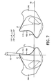
- contacting portions 41A and 41B are configured to lie at an angle ⁇ 1 ( FIGS. 7 and 8 ) (which may be constant or vary within contacting portions 41 A and 41B) with respect to the sealing plane (labeled 58 in FIG. 7 ) of cradle style sealing cushion 10 that is less than or equal to 135 degrees and greater than or equal to 30 degrees.
- contacting portions 41 A and 41 B are configured to lie at an angle ⁇ 1 with respect to sealing plane 58 that is less than or equal to 90 degrees and greater than or equal to 30 degrees.
- a complementary angle ⁇ 2 is also shown in FIG.
- ⁇ 2 is measured with respect to a plane 60 that is orthogonal to sealing plane 58 and is less than or equal to 60 degrees and greater than or equal to -45 degrees (less than or equal to 60 degrees and greater than or equal to 0 degrees in the particular exemplary embodiment).
- the distance between contacting portions 41A and 41B is 25 mm to 55 mm.
- the combination of the side stabilizing features comprising first and second stabilizing surfaces 40A and 40B and the open front (opening 50) serves to direct any air leakage away from the wearer, while blocking the flow of air leakage from the sides of cradle style sealing cushion 10.
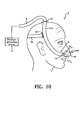
- headgear attachment points 62 serve to anchor cradle style sealing cushion 10 to the face, but an external force (e.g. gravity) of sufficient magnitude could cause cradle style sealing cushion 10 to rotate about this anchor point ( FIG. 10 ).
- the cradle style sealing cushion 10 is blocked by the patient's nose from rotating in a counterclockwise direction, but could potentially rotate clockwise away from the nose. In this situation, the seal adjacent to the face would be maintained, blocking air from jetting into the face of the wearer, while the open front of cradle style sealing cushion 10 (opening 50) facilitates air flow away from the wearer, thereby minimizing discomfort.
- FIGS. 11-13 show cradle style sealing cushions 10', 10" and 10"' according to alterative embodiments wherein first and second stabilizing surfaces 40A', 40A", 40A"' and 40B', 40B", 40B'" thereof curve around toward the nose tip to varying degrees while still maintaining a front opening 50', 50", 50"'. Maintaining a wider front opening may help to accommodate noses of extreme length, while maintaining a narrower opening may offer increased stability due to the corresponding larger stabilizing surfaces.
- FIGS. 1-13 cradle style sealing cushions 10, 10', 10" and 10'" are shown and described in a resting, non-inflated/non-deformed state (i.e., without pressurized gas therein).
- FIG. 1-13 cradle style sealing cushions 10, 10', 10" and 10'" are shown and described in a resting, non-inflated/non-deformed state (i.e., without pressurized gas therein).
- first and second stabilizing surfaces 40A-1 and 40B-1 thereof may or may not satisfy the angular specifications ( ⁇ 1 and ⁇ 2 ) described herein with respect to cradle style sealing cushion 10, but wherein in an inflated/deformed state (responsive to an internal pressure of 4-30 cmH 2 0), cradle style sealing cushion 10-1 will expand (see arrows in FIG.
- first and second stabilizing surfaces 40A-1 and 40B-1 thereof will be caused to satisfy the angular specifications ( ⁇ 1 and ⁇ 2 ) described herein with respect to cradle style sealing cushion 10 and will be caused to engage the outside of the patient's nostrils.
- the cradle style sealing cushions described herein could be constructed of a very soft material (e.g., soft silicone, a gel, or a visco-foam) that could be deformed by contact with the facial anatomy such that first and second stabilizing surfaces 40A-1 and 40B-1 thereof will be caused to satisfy the angular specifications ( ⁇ 1 and ⁇ 2 ) described herein with respect to cradle style sealing cushion 10 (in the resting state, those condition may or may not be satisfied).
- a very soft material e.g., soft silicone, a gel, or a visco-foam
- System 2-2 adapted to provide a regimen of respiratory therapy to a patient according to an alternative exemplary embodiment of the invention is generally shown in FIG. 15 .
- System 2-2 includes a pressure generating device 4 and a delivery conduit 6 as described elsewhere herein.
- System 2-2 includes an alternative patient interface device 8-2.
- Patient interface device 8-2 comprises a cradle style nasal mask structured to engage the nose of the patient that includes a cradle style sealing cushion 10-2 that is similar to cradle style sealing cushion 10.
- cradle style sealing cushion 10-2 includes a central sealing body portion 22-2 defining an internal chamber that is similar in structure to central sealing body portion 22 in that it includes first and second stabilizing surfaces 40A-2 and 40B-2 having contacting portions that satisfy the angular specifications ( ⁇ 1 and ⁇ 2 ) described herein with respect to cradle style sealing cushion 10 and a front opening 50-2 similar in structure to front opening 50.
- first and second stabilizing surfaces 40A-2 and 40B-2 having contacting portions that satisfy the angular specifications ( ⁇ 1 and ⁇ 2 ) described herein with respect to cradle style sealing cushion 10 and a front opening 50-2 similar in structure to front opening 50.
- the sides of cradle style sealing cushion 10-2 are coupled (not fluidly) to the arms of headgear assembly 64.
- the front of central sealing body portion 22-2 is provided with an orifice 66 that provides access to the inner chamber of central sealing body portion 22-2.
- An elbow conduit 68 having an exhaust port 70 is fluidly coupled to both central sealing body portion 22-2 through orifice 66 and to delivery conduit 6 so that pressured gas from pressure generating device 4 may be supplied to the inner chamber of central sealing body portion 22-2, and then to the airways of the patient.
- FIG. 16 is a top plan view of a cradle style sealing cushion 10-3 that is similar to (and may be substituted for) cradle style sealing cushion 10 (like parts are labeled with like reference numerals including a "-3" designation). However, rather than including a top wall 34 that includes a central sealing surface 38 including a single hole 39, cradle style sealing cushion 10-3 includes a top wall 34-3 that includes a central sealing surface 38-3 including a first hole 72A and a second hole 72B, wherein each hole 72A, 72B is structured to be aligned with a respective nostril of the patient.
- the first stabilizing surface (40A, 40A', 40A", 40A'", 40A-1, 40A-2, 40A-3) and the second stabilizing surface (40B, 40B', 40B", 40B"', 40B-1, 40B-2, 40B-3) each include at least a portion wherein the radius of curvature has a certain minimum value that is within a pre-defined minimum range. In the exemplary embodiment, that range is 0 mm to 15 mm.
- FIGS. 17A, 17B and 17C using stabilizing surface 40A
- the portion has a radius of curvature r that is equal to 0 (the rest of the stabilizing surface is flat with r equal to infinity), wherein in FIG. 17B , the portion has a radius of curvature r that is equal to about 3 mm (the rest of the stabilizing surface has a radius of curvature r equal to about 300 mm), and wherein in FIG. 17C , the portion comprises the entire stabilizing surface and has a radius of curvature r that is equal to about 15 mm.
- any reference signs placed between parentheses shall not be construed as limiting the claim.
- the word “comprising” or “including” does not exclude the presence of elements or steps other than those listed in a claim.
- several of these means may be embodied by one and the same item of hardware.
- the word “a” or “an” preceding an element does not exclude the presence of a plurality of such elements.
- any device claim enumerating several means several of these means may be embodied by one and the same item of hardware.
- the mere fact that certain elements are recited in mutually different dependent claims does not indicate that these elements cannot be used in combination.
Description
- The present invention pertains to patient interface devices structured to deliver a flow of breathing gas to a user, and, in particular, to a cradle style sealing cushion for a patient interface device that has side stabilizers providing an improved fit and seal.
- There are numerous situations where it is necessary or desirable to deliver a flow of breathing gas non-invasively to the airway of a patient, i.e., without intubating the patient or surgically inserting a tracheal tube into the patient's esophagus. For example, it is known to ventilate a patient using a technique known as non-invasive ventilation. It is also known to deliver positive airway pressure (PAP) therapy to treat certain medical disorders, the most notable of which is OSA. Known PAP therapies include continuous positive airway pressure (CPAP), wherein a constant positive pressure is provided to the airway of the patient in order to splint open the patient's airway, and variable airway pressure, wherein the pressure provided to the airway of the patient is varied with the patient's respiratory cycle. Such therapies are typically provided to the patient at night while the patient is sleeping.
- Non-invasive ventilation and pressure support therapies as just described involve the placement of a patient interface device including a mask component having a soft, flexible sealing cushion on the face of a patient. The mask component may be, without limitation, a nasal mask that covers the patient's nose, a nasal/oral mask that covers the patient's nose and mouth, or a full face mask that covers the patient's face. Such patient interface devices may also employ other patient contacting components, such as forehead supports, cheek pads and chin pads. The patient interface device is connected to a gas delivery tube or conduit and interfaces the ventilator or pressure support device with the airway of the patient, so that a flow of breathing gas can be delivered from the pressure/flow generating device to the airway of the patient. It is known to maintain such devices on the face of a wearer by a headgear having one or more straps adapted to fit over/around the patient's head.
- One type of known sealing cushion is called a cradle style sealing cushion. A cradle style sealing cushion is structured to rest beneath the patient's nose and provides an air-tight seal against the surfaces of the nasal septum and nostrils (and also possibly the upper lip). A patient interface assembly with such a cushion is disclosed in document
WO2005/076874 . One major disadvantage of current cradle style sealing cushions is that the seal between the cushion and the nose is very sensitive to the alignment of the cushion to the nose. For this reason, many wearers find it difficult to maintain a reliable seal when using a mask with a cradle style sealing cushion due to misalignment caused by movement of the wearer or external forces acting on the mask (e.g. from a bed pillow). When the seal is broken, the ability of the respiratory therapy device to deliver adequate airflow to the wearer may be compromised. Additionally, air leakage may be directed into the wearer's face, causing discomfort. - Accordingly, it is an object of the present invention to provide a cradle style sealing cushion that overcomes the shortcomings of conventional cradle style sealing cushions. This object is achieved according to one embodiment of the present invention by providing cradle style sealing cushion that includes side stabilizers providing an improved fit and seal.
- In one embodiment, a cradle style cushion for a patient interface device is provided that includes a central sealing body portion defining an internal chamber, the central sealing body portion including a front wall, a rear wall, a top wall and a bottom wall. The top wall includes a central sealing surface structured to engage a septum and a bottom of each nostril of a patent (and possibly the portion of the patient's mouth above the upper lip) when the patient interface device is donned by the patient, a first stabilizing surface and a second stabilizing surface, the first and second stabilizing surfaces each extending upwardly and outwardly with respect to the central sealing surface and a top edge of the front wall in a direction away from the bottom wall and being structured to wrap around and at portions thereof engage an outer side (transverse to the bottom) of a respective one of the nostrils when the patient interface device is donned by the patient, wherein the first stabilizing surface includes a first front side edge portion and the second stabilizing surface includes a second front side edge portion, and wherein the top edge of the front wall, the first front side edge portion and the second front side edge portion together define a front opening of the central sealing body portion.
- These and other objects, features, and characteristics of the present invention, as well as the methods of operation and functions of the related elements of structure and the combination of parts and economies of manufacture, will become more apparent upon consideration of the following description and the appended claims with reference to the accompanying drawings, all of which form a part of this specification, wherein like reference numerals designate corresponding parts in the various figures. It is to be expressly understood, however, that the drawings are for the purpose of illustration and description only and are not intended as a definition of the limits of the invention.
-
-
FIG. 1 is a schematic diagram of a system adapted to provide a regimen of respiratory therapy to a patient according to one exemplary embodiment of the invention; -
FIG. 2 is a front isometric view,FIG. 3 is a front elevational view,FIG. 4 is a side elevational view,FIG. 5 is a rear elevational view, andFIG. 6 is a top plan view of a cradle style sealing cushion according to an exemplary embodiment of the present invention that may be employed in a patient interface device of the system ofFIG. 1 ; -
FIG. 7 is a cross-sectional view of cradle style sealing cushion taken along lines A-A ofFIG. 6 ; -
FIG. 8 is a schematic diagram of the system ofFIG. 1 wherein the cradle style sealing cushion is shown in cross-section; -
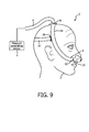
FIGS. 9 and10 are schematic diagrams of the system ofFIG. 1 illustrating the effect of gravitational or similar forces on the patient interface device; -
FIGS. 11-13 are schematic diagrams of alternative cradle style sealing cushions that may be employed in a patient interface device of the system ofFIG. 1 ; -
FIG. 14 is a schematic diagram of a system adapted to provide a regimen of respiratory therapy to a patient according to another exemplary embodiment of the invention; -
FIG. 15 is a schematic diagram of a system adapted to provide a regimen of respiratory therapy to a patient according to yet another exemplary embodiment of the invention; -
FIG. 16 is a top plan view of a cradle style sealing cushion according to an alternative exemplary embodiment of the present invention that may be employed in a patient interface device of the system ofFIG. 1 ; and -
FIGS. 17A, 17B and 17C are schematic diagrams of a cradle style sealing cushion according to another alternative exemplary embodiment of the present invention that may be employed in a patient interface device of the system ofFIG. 1 . - As used herein, the singular form of "a", "an", and "the" include plural references unless the context clearly dictates otherwise. As used herein, the statement that two or more parts or components are "coupled" shall mean that the parts are joined or operate together either directly or indirectly, i.e., through one or more intermediate parts or components, so long as a link occurs. As used herein, "directly coupled" means that two elements are directly in contact with each other. As used herein, "fixedly coupled" or "fixed" means that two components are coupled so as to move as one while maintaining a constant orientation relative to each other.
- As used herein, the word "unitary" means a component is created as a single piece or unit. That is, a component that includes pieces that are created separately and then coupled together as a unit is not a "unitary" component or body. As employed herein, the statement that two or more parts or components "engage" one another shall mean that the parts exert a force against one another either directly or through one or more intermediate parts or components. As employed herein, the term "number" shall mean one or an integer greater than one (i.e., a plurality).
- Directional phrases used herein, such as, for example and without limitation, top, bottom, left, right, upper, lower, front, back, and derivatives thereof, relate to the orientation of the elements shown in the drawings and are not limiting upon the claims unless expressly recited therein.
- A
system 2 adapted to provide a regimen of respiratory therapy to a patient according to one exemplary embodiment of the invention is generally shown inFIG. 1 .System 2 includes apressure generating device 4, adelivery conduit 6, and apatient interface device 8. Pressure generatingdevice 4 is structured to generate a flow of breathing gas and may include, without limitation, ventilators, constant pressure support devices (such as a continuous positive airway pressure device, or CPAP device), variable pressure devices (e.g., BiPAP®, Bi-Flex®, or C-Flex™ devices manufactured and distributed by Philips Respironics of Murrysville, Pennsylvania), and auto-titration pressure support devices.Delivery conduit 6 is structured to communicate the flow of breathing gas frompressure generating device 4 topatient interface device 8. - In the exemplary embodiment,
patient interface device 8 comprises a cradle style nasal mask structured to engage the nose of the patient and provide a seal against the surfaces of the nasal septum and nostrils (and possibly the portion of the patient's mouth above the upper lip) as described in detail herein. In the present embodiment,patient interface device 8 includes a cradlestyle sealing cushion 10 coupled to atubing assembly 12. As seen inFIG. 1 ,tubing assembly 12 includes afirst arm 14A structured to rest along a first side of the patient's head and asecond arm 14B structured to rest along a second side of the patient's head whenpatient interface device 8 is donned by the patient. A first end offirst arm 14A and a first end ofsecond arm 14B are each fluidly coupled to cradlestyle sealing cushion 10. In addition, a second end offirst arm 14A and a second end ofsecond arm 14B are each fluidly coupled to acoupling connector 16 structured to rest on top of the head of the patient whenpatient interface device 8 is donned by the patient.Delivery conduit 6 is fluidly coupled tocoupling connector 16 to allow the flow of breathing gas frompressure generating device 4 to be communicated to cradlestyle sealing cushion 10 throughtubing assembly 12, and then, to the airway of a patient.Straps 18 of a headgear component are attached tofirst arm 14A andsecond arm 14B viaattachment members 20 to securepatient interface device 8 to the patient's head. -
FIG. 2 is a front isometric view,FIG. 3 is a front elevational view,FIG. 4 is a side elevational view,FIG. 5 is a rear elevational view, andFIG. 6 is a top plan view of cradlestyle sealing cushion 10 according to an exemplary embodiment of the present invention. In the exemplary embodiment, cradlestyle sealing cushion 10 is defined from a unitary piece of soft, flexible, cushiony material, such as, without limitation, silicone rubber, an appropriately soft thermoplastic elastomer, a fabric, or any combination of such materials. It will be understood, however, that cradlestyle sealing cushion 10 does not need to be unitary within the scope of the present invention. Rather, cradlestyle sealing cushion 10, and the parts thereof, may be made of separate components that are coupled to one another by suitable means. - Cradle
style sealing cushion 10 includes a centralsealing body portion 22 defining an internal chamber, afirst port portion 24A provided on and extending from a first side of centralsealing body portion 22, and asecond port portion 24B provided on and extending from a second, opposite side of centralsealing body portion 22.First port portion 24A andsecond port portion 24B are fluidly coupled to the internal chamber of centralsealing body portion 22.First port portion 24A includes afirst opening 26A and is structured to be fluidly coupled tofirst arm 14A, whilesecond port portion 24B includes asecond opening 26B and is structured to be fluidly coupled tosecond arm 14B. - Central sealing
body portion 22 includes afront side 28 including afront wall 29 and arear side 30 oppositefront side 28 and including arear wall 31. A plurality of exhaust holes 32 are provided infront wall 29 and act as an exhaust port forpatient interface device 8. Exhaust holes 32 may be directed in any direction (or combination of directions) including directly away from the wearer (as shown in the illustrated embodiment), up towards the top of the wearer's head, down towards the wearer's chin, or to the sides. Alternatively, an exhaust port in the form of a semi-permeable porous material, such as a woven fabric, may be provided in place of exhaust holes 32. Central sealingbody portion 22 also includes atop wall 34 andbottom wall 36 oppositetop wall 34. -
Top wall 34 includes acentral sealing surface 38 including a hole 39 (providing access to the internal chamber of central sealing body portion 22), and first and second stabilizingsurfaces central sealing surface 38 is structured to engage and form a seal against a septum and a bottom of each nostril of a patent (and possibly the portion of the patient's mouth above the upper lip in one particular embodiment) when the patient interface device is donned by the patient. In addition, first and second stabilizingsurfaces patient interface device 8 is donned by the patient. - As seen in
FIGS. 2 and 3 , in the exemplary embodiment, the junction of first and second stabilizingsurfaces central sealing surface 38 each comprises a rounded, filleted portion (forming a part of first and second stabilizingsurfaces surface 40A and second stabilizingsurface 40B are provided between the top edge offront wall 29 and the top edge ofrear wall 31. In the exemplary, non-limiting embodiment, first stabilizingsurface 40A has a generally triangular shape including abase portion 42A, a frontside edge portion 44A, a rearside edge portion 46A, and anapex portion 48A. Similarly, in the exemplary, non-limiting embodiment, second stabilizingsurface 40B also has a generally triangular shape including abase portion 42B, a frontside edge portion 44B, a rearside edge portion 46B, and anapex portion 48B. - Thus, as seen most readily in
FIG. 3 , the top edge offront wall 29, frontside edge portion 44A and frontside edge portion 44B together define afront opening 50 of centralsealing body portion 22 which exposes the front and top of the patient's nose (i.e., the cradlestyle sealing cushion 10 does not cover the front and top of the patient's nose). The significance of this feature is described elsewhere herein. Also, the top edge ofrear wall 31, rearside edge portion 46A and rearside edge portion 46B together define arear opening 51 of centralsealing body portion 22 that is structured to receive the patient's nose therethrough. In alternative embodiments, first and second stabilizingsurfaces - Moreover, as seen in
FIG. 3 , cradlestyle sealing cushion 10 has atransverse axis 52 that is a line of symmetry for cradlestyle sealing cushion 10.Transverse axis 52 is perpendicular to alongitudinal axis 54 of centralsealing body portion 22, shown inFIGS. 3 and4 . In addition, as shown inFIG. 6 , acenter line 56 ofcentral sealing surface 38 extends through the middle ofcentral sealing surface 38 from the center of front side 28 (and front wall 29) to the center of rear side 30 (and rear wall 31).Center line 56 lies in and defines a sealing plane of cradlestyle sealing cushion 10. In the non-limiting, exemplary embodiment, the sealing plane of cradlestyle sealing cushion 10, when viewed from the front as shown inFIG. 3 , is not orthogonal totransverse axis 52, but instead is angled and extends/slopes downwardly from front to back at an angle of slightly more than zero to thirty degrees with respect to a line or axis that is orthogonal totransverse axis 52. - In another, exemplary embodiment, the sealing plane of cradle
style sealing cushion 10, when viewed from the front as shown inFIG. 3 , is a orthogonal totransverse axis 52. In still another, exemplary embodiment,central sealing surface 38 is not flat, but rather actually has an arc where the apex is not necessarily at the front edge but rather closer to the middle ofcentral sealing surface 38. These axes, lines and planes help to define another important feature of cradlestyle sealing cushion 10. In particular, first and second stabilizingsurfaces portion patient interface device 8 is donned by the patient. In the exemplary embodiment, at any point along the surface of contactingportions portions FIGS. 7 and8 ) (which may be constant or vary within contactingportions FIG. 7 ) of cradlestyle sealing cushion 10 that is less than or equal to 135 degrees and greater than or equal to 30 degrees. In one particular exemplary embodiment, at any point along the surface of contactingportions portions plane 58 that is less than or equal to 90 degrees and greater than or equal to 30 degrees. A complementary angle θ2 is also shown inFIG. 7 , wherein θ2 is measured with respect to aplane 60 that is orthogonal to sealingplane 58 and is less than or equal to 60 degrees and greater than or equal to -45 degrees (less than or equal to 60 degrees and greater than or equal to 0 degrees in the particular exemplary embodiment). - In the exemplary embodiment, the distance between contacting
portions - The combination of the side stabilizing features comprising first and second stabilizing
surfaces style sealing cushion 10. In particular, as seen inFIGS. 9 and10 , headgear attachment points 62 serve to anchor cradlestyle sealing cushion 10 to the face, but an external force (e.g. gravity) of sufficient magnitude could cause cradlestyle sealing cushion 10 to rotate about this anchor point (FIG. 10 ). With reference toFIG. 10 , the cradlestyle sealing cushion 10 is blocked by the patient's nose from rotating in a counterclockwise direction, but could potentially rotate clockwise away from the nose. In this situation, the seal adjacent to the face would be maintained, blocking air from jetting into the face of the wearer, while the open front of cradle style sealing cushion 10 (opening 50) facilitates air flow away from the wearer, thereby minimizing discomfort. -
FIGS. 11-13 show cradlestyle sealing cushions 10', 10" and 10"' according to alterative embodiments wherein first and second stabilizingsurfaces 40A', 40A", 40A"' and 40B', 40B", 40B'" thereof curve around toward the nose tip to varying degrees while still maintaining afront opening 50', 50", 50"'. Maintaining a wider front opening may help to accommodate noses of extreme length, while maintaining a narrower opening may offer increased stability due to the corresponding larger stabilizing surfaces. - In the embodiments of
FIGS. 1-13 , cradlestyle sealing cushions FIG. 14 shows an alternative system 2-1 having an alternative cradle style sealing cushion 10-1 wherein in a resting, non-inflated/non-deformed state, first and second stabilizingsurfaces 40A-1 and 40B-1 thereof may or may not satisfy the angular specifications (θ1 and θ2) described herein with respect to cradlestyle sealing cushion 10, but wherein in an inflated/deformed state (responsive to an internal pressure of 4-30 cmH20), cradle style sealing cushion 10-1 will expand (see arrows inFIG. 14 ) and first and second stabilizingsurfaces 40A-1 and 40B-1 thereofwill be caused to satisfy the angular specifications (θ1 and θ2) described herein with respect to cradlestyle sealing cushion 10 and will be caused to engage the outside of the patient's nostrils. Additionally, the cradle style sealing cushions described herein could be constructed of a very soft material (e.g., soft silicone, a gel, or a visco-foam) that could be deformed by contact with the facial anatomy such that first and second stabilizingsurfaces 40A-1 and 40B-1 thereof will be caused to satisfy the angular specifications (θ1 and θ2) described herein with respect to cradle style sealing cushion 10 (in the resting state, those condition may or may not be satisfied). - A system 2-2 adapted to provide a regimen of respiratory therapy to a patient according to an alternative exemplary embodiment of the invention is generally shown in
FIG. 15 . System 2-2 includes apressure generating device 4 and adelivery conduit 6 as described elsewhere herein. System 2-2 includes an alternative patient interface device 8-2. Patient interface device 8-2 comprises a cradle style nasal mask structured to engage the nose of the patient that includes a cradle style sealing cushion 10-2 that is similar to cradlestyle sealing cushion 10. More specifically, cradle style sealing cushion 10-2 includes a central sealing body portion 22-2 defining an internal chamber that is similar in structure to centralsealing body portion 22 in that it includes first and second stabilizingsurfaces 40A-2 and 40B-2 having contacting portions that satisfy the angular specifications (θ1 and θ2) described herein with respect to cradlestyle sealing cushion 10 and a front opening 50-2 similar in structure tofront opening 50. However, rather than havingport portions tubing assembly 12, the sides of cradle style sealing cushion 10-2 are coupled (not fluidly) to the arms ofheadgear assembly 64. In addition, the front of central sealing body portion 22-2 is provided with anorifice 66 that provides access to the inner chamber of central sealing body portion 22-2. Anelbow conduit 68 having anexhaust port 70 is fluidly coupled to both central sealing body portion 22-2 throughorifice 66 and todelivery conduit 6 so that pressured gas frompressure generating device 4 may be supplied to the inner chamber of central sealing body portion 22-2, and then to the airways of the patient. -
FIG. 16 is a top plan view of a cradle style sealing cushion 10-3 that is similar to (and may be substituted for) cradle style sealing cushion 10 (like parts are labeled with like reference numerals including a "-3" designation). However, rather than including atop wall 34 that includes acentral sealing surface 38 including asingle hole 39, cradle style sealing cushion 10-3 includes a top wall 34-3 that includes a central sealing surface 38-3 including afirst hole 72A and asecond hole 72B, wherein eachhole - Furthermore, according to yet another embodiment of the present invention, the first stabilizing surface (40A, 40A', 40A", 40A'", 40A-1, 40A-2, 40A-3) and the second stabilizing surface (40B, 40B', 40B", 40B"', 40B-1, 40B-2, 40B-3) (including the transition between the central sealing surface and such side stabilizing surfaces) each include at least a portion wherein the radius of curvature has a certain minimum value that is within a pre-defined minimum range. In the exemplary embodiment, that range is 0 mm to 15 mm. This embodiment is shown schematically in
FIGS. 17A, 17B and 17C (using stabilizingsurface 40A), wherein inFIG. 17A , the portion has a radius of curvature r that is equal to 0 (the rest of the stabilizing surface is flat with r equal to infinity), wherein inFIG. 17B , the portion has a radius of curvature r that is equal to about 3 mm (the rest of the stabilizing surface has a radius of curvature r equal to about 300 mm), and wherein inFIG. 17C , the portion comprises the entire stabilizing surface and has a radius of curvature r that is equal to about 15 mm. - In the claims, any reference signs placed between parentheses shall not be construed as limiting the claim. The word "comprising" or "including" does not exclude the presence of elements or steps other than those listed in a claim. In a device claim enumerating several means, several of these means may be embodied by one and the same item of hardware. The word "a" or "an" preceding an element does not exclude the presence of a plurality of such elements. In any device claim enumerating several means, several of these means may be embodied by one and the same item of hardware. The mere fact that certain elements are recited in mutually different dependent claims does not indicate that these elements cannot be used in combination.
- Although the invention has been described in detail for the purpose of illustration based on what is currently considered to be the most practical and preferred embodiments, it is to be understood that such detail is solely for that purpose and that the invention is not limited to the disclosed embodiments, but, on the contrary, is intended to cover modifications and equivalent arrangements that are within the scope of the appended claims. For example, it is to be understood that the present invention contemplates that, to the extent possible, one or more features of any embodiment can be combined with one or more features of any other embodiment.
Claims (17)
- A cradle style cushion (10, 10', 10", 10"', 10-1, 10-2, 10-3) for a patient interface device (8, 8-1, 8-2), comprising:a central sealing body portion (22, 22-1, 22-2, 22-3) defining an internal chamber, the central sealing body portion comprising:a front wall (29),a rear wall (31),a top wall (34), anda bottom wall (36), the top wall includinga central sealing surface (38) structured to engage a septum and a bottom of each nostril of a patient when the patient interface device is donned by the patient,a first stabilizing surface (40A, 40A', 40A", 40A"', 40A-1, 40A-2, 40A-3) anda second stabilizing surface (40B, 40B', 40B", 40B"', 40B-1, 40B-2, 40B-3), characterised in that the first and second stabilizing surfaces each extend upwardly and outwardly with respect to the central sealing surface and a top edge of the front wall in a direction away from the bottom wall and being structured to wrap around and at portions thereof engage an outer side of a respective one of the nostrils of the patient when the patient interface device is donned by the patient, wherein the first stabilizing surface includes a first front side edge portion (44A) and the second stabilizing surface includes a second front side edge portion (44B), and wherein the top edge of the front wall, the first front side edge portion and the second front side edge portion together define a front opening (50) of the central sealing body portion.
- The cradle style cushion according to claim 1, wherein a center line (56) of the central sealing surface extends through a middle of the central sealing surface from a center of the front wall to a center of the rear wall, wherein the center line lies in and defines a sealing plane of the cradle style sealing cushion, wherein the first stabilizing surface includes a first contacting portion that is structured to engage the outside of a first one of the nostrils when the patient interface device is donned by the patient, wherein the second stabilizing surface includes a second contacting portion that is structured to engage the outside of a second one of the nostrils when the patient interface device is donned by the patient, and wherein at any point along a surface of each of the first and second contacting portions, the first and second contacting portions are each configured to lie at an angle with respect to the sealing plane that is less than or equal to 135 degrees and greater than or equal to 30 degrees.
- The cradle style cushion according to claim 2, wherein at any point along the surface of each of the first and second contacting portions, the first and second contacting portions are each configured to lie at an angle with respect to the sealing plane that is less than or equal to 90 degrees and greater than or equal to 30 degrees.
- The cradle style cushion according to claim 3, wherein at any point along the surface of each of the first and second contacting portions, the first and second contacting portions are each configured to lie at an angle with respect to the sealing plane that is less than or equal to 90 degrees and greater than or equal to 30 degrees when the cradle style cushion is in a resting state and is not filled with a pressurized gas of 4-30 cmH20.
- The cradle style cushion according to claim 3, wherein at any point along the surface of each of the first and second contacting portions, the first and second contacting portions are each configured to lie at an angle with respect to the sealing plane that is less than or equal to 90 degrees and greater than or equal to 30 degrees responsive to the cradle style cushion being filled with a pressurized gas of 4-30 cmH20.
- The cradle style cushion according to claim 1, wherein the first stabilizing surface and the second stabilizing surface are each provided between the top edge of front wall and a top edge of the rear wall.
- The cradle style cushion according to claim 1, wherein the first stabilizing surface has a generally triangular shape including a first base portion, the first front side edge portion, a first rear side edge portion, and a first apex portion, and wherein the second stabilizing surface has a generally triangular shape including a second base portion, the second front side edge portion, a second rear side edge portion, and a second apex portion.
- The cradle style cushion according to claim 1, the central sealing surface includes a single hole (39).
- The cradle style cushion according to claim 1, the central sealing surface includes a first hole (72A) and a second hole (72B).
- The cradle style cushion according to claim 1, further comprising a first port portion (24A) provided on and extending from a first side of the central sealing body portion, and a second port portion (24B) provided on and extending from a second, opposite side of the central sealing body portion, the first port portion and the second port portion being fluidly coupled to the internal chamber of the central sealing body portion, the first port portion including a first opening (26A) and the second port portion including a second opening (26B).
- The cradle style cushion according to claim 1, wherein the central sealing body portion is provided with an orifice that provides access to the inner chamber of the central sealing body portion, the orifice being structured to be coupled to an elbow conduit (68).
- The cradle style cushion according to claim 1, wherein at least a portion of the first stabilizing surface has a first radius of curvature of 0 mm to 15 mm and wherein at least a portion of the second stabilizing surface has a second radius of curvature of 0 mm to 15 mm.
- The cradle style cushion according to claim 1, wherein the central sealing surface is structured to engage a portion of the patient's mouth above an upper lip of the patient when the patient interface device is donned by the patient.
- The cradle style cushion according to claim 3, wherein at any point along the surface of each of the first and second contacting portions, the first and second contacting portions are each configured to lie at an angle with respect to the sealing plane that is less than or equal to 90 degrees and greater than or equal to 30 degrees responsive to the cradle style cushion being deformed by the patient's facial anatomy.
- The cradle style cushion according to claim 1, wherein the first stabilizing surface and the second stabilizing surface each have a generally triangular, rectangular or trapezoidal shape.
- A patient interface device including a cradle style cushion according to claim 1.
- A system (2, 2-1, 2-2) for delivering a flow of breathing gas to a patient, comprising a pressure generating system (4) structured to generate the flow of breathing gas and a patient interface device fluidly coupled to the pressure generating system, wherein the patient interface device includes a cradle style cushion according to claim 1.
Applications Claiming Priority (2)
| Application Number | Priority Date | Filing Date | Title |
|---|---|---|---|
| US201261671926P | 2012-07-16 | 2012-07-16 | |
| PCT/IB2013/055440 WO2014013371A1 (en) | 2012-07-16 | 2013-07-03 | Cradle cushion having side stabilizers |
Publications (2)
| Publication Number | Publication Date |
|---|---|
| EP2869878A1 EP2869878A1 (en) | 2015-05-13 |
| EP2869878B1 true EP2869878B1 (en) | 2015-12-23 |
Family
ID=49170758
Family Applications (1)
| Application Number | Title | Priority Date | Filing Date |
|---|---|---|---|
| EP13762569.5A Active EP2869878B1 (en) | 2012-07-16 | 2013-07-03 | Cradle cushion having side stabilizers |
Country Status (7)
| Country | Link |
|---|---|
| US (4) | US9764107B2 (en) |
| EP (1) | EP2869878B1 (en) |
| JP (1) | JP5895103B2 (en) |
| CN (1) | CN104487121B (en) |
| BR (1) | BR112015000758B1 (en) |
| RU (1) | RU2640443C2 (en) |
| WO (1) | WO2014013371A1 (en) |
Families Citing this family (41)
| Publication number | Priority date | Publication date | Assignee | Title |
|---|---|---|---|---|
| EP4282456A3 (en) | 2011-04-15 | 2024-02-14 | Fisher & Paykel Healthcare Limited | Interface comprising a rolling nasal bridge portion |
| US10603456B2 (en) | 2011-04-15 | 2020-03-31 | Fisher & Paykel Healthcare Limited | Interface comprising a nasal sealing portion |
| EP4279106A3 (en) | 2012-09-04 | 2024-01-17 | Fisher & Paykel Healthcare Limited | Valsalva mask |
| GB2522582B (en) * | 2012-11-16 | 2019-09-04 | Fisher & Paykel Healthcare Ltd | Nasal seal and respiratory interface |
| NZ777015A (en) | 2013-01-16 | 2022-12-23 | ResMed Pty Ltd | Patient interface and method for making same |
| SG11201508589QA (en) | 2013-04-26 | 2015-11-27 | Fisher & Paykel Healthcare Ltd | Headgear for breathing mask |
| DE112014003604T5 (en) | 2013-08-05 | 2016-06-02 | Fisher & Paykel Healthcare Limited | Seal for a patient interface, junction assemblies, and aspects thereof |
| WO2015070289A1 (en) * | 2013-11-15 | 2015-05-21 | Resmed Limited | Patient interface and method for making same |
| SG11201608616VA (en) | 2014-06-17 | 2017-01-27 | Fisher & Paykel Healthcare Ltd | Patient interfaces |
| GB2544428B (en) | 2014-08-25 | 2021-03-24 | Fisher & Paykel Healthcare Ltd | A cushion module for a respiratory interface |
| JP2016049132A (en) * | 2014-08-28 | 2016-04-11 | アトムメディカル株式会社 | Cannula apparatus |
| NZ732522A (en) * | 2014-11-26 | 2023-04-28 | ResMed Pty Ltd | Textile patient interface |
| JP6720186B2 (en) * | 2014-12-30 | 2020-07-08 | コーニンクレッカ フィリップス エヌ ヴェKoninklijke Philips N.V. | Patient interface device |
| USD799699S1 (en) | 2015-10-09 | 2017-10-10 | Koninklijke Philips N.V. | Mask frame for CPAP therapy |
| EP3344318B1 (en) | 2015-09-04 | 2021-11-03 | Fisher & Paykel Healthcare Limited | Patient interfaces |
| CN114191672B (en) | 2016-01-14 | 2024-02-27 | 瑞思迈私人有限公司 | Oral nasal patient interface |
| EP3405244B1 (en) | 2016-01-21 | 2021-11-03 | ResMed Pty Ltd | Adjustable headgear tubing for a patient interface |
| USD825053S1 (en) * | 2016-03-23 | 2018-08-07 | Fisher & Paykel Healthcare Limited | Nasal cannula |
| EP3936179A1 (en) | 2016-04-28 | 2022-01-12 | ResMed Pty Ltd | Patient interface |
| USD844132S1 (en) | 2016-07-01 | 2019-03-26 | Fisher & Paykel Healthcare Limited | Cannula pad |
| CN109803706B (en) * | 2016-10-04 | 2021-12-31 | 皇家飞利浦有限公司 | Conduit, tubing assembly and patient interface device |
| EP4122516A1 (en) | 2016-10-05 | 2023-01-25 | Fisher & Paykel Healthcare Limited | Patient interfaces |
| CN106730192B (en) * | 2016-11-23 | 2018-12-18 | 中国人民解放军第三军医大学第三附属医院 | Noninvasive ventilator lower jaw fixes device |
| USD829322S1 (en) * | 2016-12-05 | 2018-09-25 | Koninklijke Philips N.V. | Mask |
| USD824020S1 (en) | 2017-02-23 | 2018-07-24 | Fisher & Paykel Healthcare Limited | Cushion assembly for breathing mask assembly |
| USD823455S1 (en) | 2017-02-23 | 2018-07-17 | Fisher & Paykel Healthcare Limited | Cushion assembly for breathing mask assembly |
| USD823454S1 (en) | 2017-02-23 | 2018-07-17 | Fisher & Paykel Healthcare Limited | Cushion assembly for breathing mask assembly |
| WO2019063339A1 (en) * | 2017-09-28 | 2019-04-04 | Koninklijke Philips N.V. | Cushion with protrusion and patient interface device including same |
| US20190298954A1 (en) * | 2018-03-30 | 2019-10-03 | Koninklijke Philips N.V. | Adjustable frame for an interface device |
| USD884153S1 (en) | 2018-04-04 | 2020-05-12 | Fisher & Paykel Healthcare Limited | Frame for a mask assembly |
| USD942614S1 (en) | 2018-07-10 | 2022-02-01 | ResMed Pty Ltd | Combined cushion and frame module for patient interface |
| USD924388S1 (en) | 2018-07-10 | 2021-07-06 | ResMed Pty Ltd | Patient interface |
| USD862686S1 (en) * | 2018-07-16 | 2019-10-08 | Mohamed Aly Helmy Mohamed | CPAP cannula device |
| AU2019323224B2 (en) | 2018-08-20 | 2021-10-21 | ResMed Pty Ltd | Headgear for a patient interface |
| US11406781B2 (en) | 2018-08-20 | 2022-08-09 | ResMed Pty Ltd | Patient interface |
| USD942615S1 (en) | 2018-09-12 | 2022-02-01 | ResMed Pty Ltd | Patient interface |
| AU2019361356A1 (en) | 2018-10-16 | 2021-05-13 | ResMed Pty Ltd | Patient interface |
| US20200246572A1 (en) | 2018-10-16 | 2020-08-06 | ResMed Pty Ltd | Textile seal-forming structure with multiple curvatures |
| USD978332S1 (en) * | 2019-03-01 | 2023-02-14 | Koninklijke Phlips N.V. | Medical device |
| US11844887B2 (en) | 2019-10-16 | 2023-12-19 | ResMed Pty Ltd | Textile seal-forming structure with multiple curvatures |
| CN115485006A (en) * | 2020-03-20 | 2022-12-16 | 瑞思迈私人有限公司 | Patient interface and occipital anchor |
Family Cites Families (38)
| Publication number | Priority date | Publication date | Assignee | Title |
|---|---|---|---|---|
| EP0406258A4 (en) | 1988-03-23 | 1991-03-13 | Christa Ursula Palfy | Nasal tube holder |
| US5724965A (en) | 1995-06-06 | 1998-03-10 | Respironics Inc. | Nasal mask |
| US6119694A (en) | 1997-07-24 | 2000-09-19 | Respironics Georgia, Inc. | Nasal mask and headgear |
| US5931854A (en) * | 1998-01-26 | 1999-08-03 | Dillon; Michael M. | Nasal dilator |
| NZ750285A (en) * | 2003-02-21 | 2020-08-28 | ResMed Pty Ltd | Nasal assembly |
| US7178525B2 (en) * | 2004-02-06 | 2007-02-20 | Ric Investments, Llc | Patient interface assembly supported under the mandible |
| US7975694B2 (en) * | 2005-10-24 | 2011-07-12 | Koninklijke Philips Electronics N.V. | Non-intrusive mask interface with nasal support |
| CN101516427B (en) * | 2006-07-28 | 2012-08-08 | 雷斯梅德有限公司 | Delivery of respiratory therapy |
| NZ596570A (en) * | 2006-07-28 | 2014-02-28 | Resmed Ltd | Delivery of respiratory therapy |
| US8161971B2 (en) | 2006-08-04 | 2012-04-24 | Ric Investments, Llc | Nasal and oral patient interface |
| EP2481434B1 (en) * | 2006-12-15 | 2016-04-13 | ResMed Ltd. | Delivery of respiratory therapy |
| EP2452715B1 (en) * | 2007-07-30 | 2021-12-29 | ResMed Pty Ltd | Patient interface |
| JP5462798B2 (en) * | 2007-11-19 | 2014-04-02 | コーニンクレッカ フィリップス エヌ ヴェ | Patient interface device including a coating adhesive layer |
| US20110000492A1 (en) * | 2008-03-04 | 2011-01-06 | Resmed Ltd | Foam respiratory mask |
| EP3639878B1 (en) | 2008-05-12 | 2022-02-09 | Fisher & Paykel Healthcare Limited | Patient interface |
| US10792451B2 (en) | 2008-05-12 | 2020-10-06 | Fisher & Paykel Healthcare Limited | Patient interface and aspects thereof |
| US8291906B2 (en) * | 2008-06-04 | 2012-10-23 | Resmed Limited | Patient interface systems |
| US8905031B2 (en) * | 2008-06-04 | 2014-12-09 | Resmed Limited | Patient interface systems |
| CN103656823B (en) | 2008-11-27 | 2016-09-07 | 帝人制药株式会社 | Breathing mask wear part and breathing mask |
| RU2392010C1 (en) * | 2008-12-11 | 2010-06-20 | Евгений Васильевич Головихин | Breathing exercise device |
| TWI362888B (en) | 2008-12-24 | 2012-04-21 | Acer Inc | Encoding and decoding method for video screen layout, encoding device, decoding device, and data structure |
| CN111973854B (en) * | 2009-05-12 | 2024-02-13 | 费雪派克医疗保健有限公司 | Patient interface and aspects thereof |
| EP3639877A1 (en) | 2009-06-02 | 2020-04-22 | ResMed Pty Ltd | Unobtrusive nasal mask |
| CN101954139B (en) * | 2009-06-04 | 2016-01-20 | 瑞思迈有限公司 | For the cushion of face shield |
| CN101954130B (en) | 2009-07-14 | 2013-06-05 | 昆山福宏康复科技有限公司 | Intravenous drip injection monitor |
| US10265492B2 (en) * | 2010-04-30 | 2019-04-23 | Resmed Limited | Respiratory mask |
| US20110315145A1 (en) | 2010-06-28 | 2011-12-29 | Beevers Timothy R | Infant friendly nasal cpap canula seal |
| EP2621573B1 (en) * | 2010-09-30 | 2016-12-21 | ResMed Limited | Mask system |
| NZ625429A (en) | 2010-09-30 | 2015-12-24 | Resmed Ltd | Patient interface systems |
| CN103328030A (en) * | 2010-10-25 | 2013-09-25 | 因斯利普科技有限公司 | Butterfly nasal mask |
| WO2012061783A1 (en) | 2010-11-04 | 2012-05-10 | Sleep Science Llc | Breathing apparatus |
| RU2013133933A (en) * | 2010-12-20 | 2015-01-27 | Конинклейке Филипс Электроникс Н.В. | PATIENT INTERFACE HAVING TURNED WRAP FROM FABRIC |
| US10603456B2 (en) | 2011-04-15 | 2020-03-31 | Fisher & Paykel Healthcare Limited | Interface comprising a nasal sealing portion |
| WO2013066195A1 (en) * | 2011-10-31 | 2013-05-10 | Fisher & Paykel Healthcare Limited | Interface comprising a nasal sealing portion |
| CN103796700B (en) * | 2011-07-12 | 2017-05-24 | 瑞思迈有限公司 | Textile mask systems |
| US20140251340A1 (en) | 2011-10-21 | 2014-09-11 | Koninklijke Philips N.V. | Patient interface device for being connected to a patient's respiratory system and associated methods |
| US20130160772A1 (en) * | 2011-12-27 | 2013-06-27 | Farrokh Tabrizchi | Multi-functional nasal cannula |
| US10238827B2 (en) * | 2012-03-12 | 2019-03-26 | Mark T. Holtzapple | Air-delivery system for breathing-assist devices |
-
2013
- 2013-07-03 WO PCT/IB2013/055440 patent/WO2014013371A1/en active Application Filing
- 2013-07-03 BR BR112015000758-9A patent/BR112015000758B1/en active IP Right Grant
- 2013-07-03 CN CN201380037953.9A patent/CN104487121B/en active Active
- 2013-07-03 US US14/414,288 patent/US9764107B2/en active Active
- 2013-07-03 RU RU2015105011A patent/RU2640443C2/en active
- 2013-07-03 EP EP13762569.5A patent/EP2869878B1/en active Active
- 2013-07-03 JP JP2015522193A patent/JP5895103B2/en active Active
-
2017
- 2017-08-01 US US15/665,782 patent/US20170326321A1/en not_active Abandoned
-
2021
- 2021-06-25 US US17/358,221 patent/US11890417B2/en active Active
-
2023
- 2023-12-22 US US18/393,826 patent/US20240123173A1/en active Pending
Also Published As
| Publication number | Publication date |
|---|---|
| US20240123173A1 (en) | 2024-04-18 |
| JP5895103B2 (en) | 2016-03-30 |
| US11890417B2 (en) | 2024-02-06 |
| RU2015105011A (en) | 2016-08-27 |
| BR112015000758A2 (en) | 2017-06-27 |
| RU2640443C2 (en) | 2018-01-09 |
| US20150182719A1 (en) | 2015-07-02 |
| WO2014013371A1 (en) | 2014-01-23 |
| JP2015522369A (en) | 2015-08-06 |
| BR112015000758B1 (en) | 2021-07-13 |
| US20170326321A1 (en) | 2017-11-16 |
| US20210361898A1 (en) | 2021-11-25 |
| CN104487121A (en) | 2015-04-01 |
| EP2869878A1 (en) | 2015-05-13 |
| US9764107B2 (en) | 2017-09-19 |
| CN104487121B (en) | 2016-07-06 |
Similar Documents
| Publication | Publication Date | Title |
|---|---|---|
| US11890417B2 (en) | Cradle cushion having side stabilizers | |
| EP2968820B1 (en) | Subnasal sealing cushion | |
| EP3240597B1 (en) | Patient interface device having a custom cushion support assembly | |
| EP2552527B1 (en) | Respiratory mask with ribbed contacting surface | |
| US10737052B2 (en) | Fluid coupling member including valve member | |
| EP2608833B1 (en) | Cushion for a patient interface device | |
| EP2849831B1 (en) | Anti-asphyxia valve assembly | |
| EP2849828B1 (en) | Sealing cushion and patient interface device employing same | |
| EP2861286B1 (en) | Sealing cushion having angled sealing flap | |
| US9333314B2 (en) | Patient interface with torque-resistant connection | |
| WO2015033287A1 (en) | Patient interface device with drawstring adjustment | |
| EP2523718A2 (en) | Replaceable nasal pillow | |
| US20140196720A1 (en) | Nasal cushion including a confortable septum/nare seal | |
| WO2015092621A1 (en) | Oral sealing segment for patient interface device | |
| US20150128949A1 (en) | Patient interface device having headgear providing integrated gas flow and delivery | |
| EP3522967B1 (en) | Magnetic anti-crush feature for conduit | |
| WO2012073147A1 (en) | Patient interface device with multi-axis elbow conduit |
Legal Events
| Date | Code | Title | Description |
|---|---|---|---|
| PUAI | Public reference made under article 153(3) epc to a published international application that has entered the european phase |
Free format text: ORIGINAL CODE: 0009012 |
|
| 17P | Request for examination filed |
Effective date: 20150204 |
|
| AK | Designated contracting states |
Kind code of ref document: A1 Designated state(s): AL AT BE BG CH CY CZ DE DK EE ES FI FR GB GR HR HU IE IS IT LI LT LU LV MC MK MT NL NO PL PT RO RS SE SI SK SM TR |
|
| AX | Request for extension of the european patent |
Extension state: BA ME |
|
| GRAP | Despatch of communication of intention to grant a patent |
Free format text: ORIGINAL CODE: EPIDOSNIGR1 |
|
| INTG | Intention to grant announced |
Effective date: 20150624 |
|
| DAX | Request for extension of the european patent (deleted) | ||
| GRAS | Grant fee paid |
Free format text: ORIGINAL CODE: EPIDOSNIGR3 |
|
| GRAA | (expected) grant |
Free format text: ORIGINAL CODE: 0009210 |
|
| AK | Designated contracting states |
Kind code of ref document: B1 Designated state(s): AL AT BE BG CH CY CZ DE DK EE ES FI FR GB GR HR HU IE IS IT LI LT LU LV MC MK MT NL NO PL PT RO RS SE SI SK SM TR |
|
| REG | Reference to a national code |
Ref country code: GB Ref legal event code: FG4D |
|
| REG | Reference to a national code |
Ref country code: CH Ref legal event code: EP |
|
| REG | Reference to a national code |
Ref country code: IE Ref legal event code: FG4D |
|
| REG | Reference to a national code |
Ref country code: AT Ref legal event code: REF Ref document number: 766254 Country of ref document: AT Kind code of ref document: T Effective date: 20160115 |
|
| REG | Reference to a national code |
Ref country code: DE Ref legal event code: R096 Ref document number: 602013004269 Country of ref document: DE |
|
| REG | Reference to a national code |
Ref country code: LT Ref legal event code: MG4D |
|
| REG | Reference to a national code |
Ref country code: NL Ref legal event code: MP Effective date: 20151223 |
|
| PG25 | Lapsed in a contracting state [announced via postgrant information from national office to epo] |
Ref country code: NO Free format text: LAPSE BECAUSE OF FAILURE TO SUBMIT A TRANSLATION OF THE DESCRIPTION OR TO PAY THE FEE WITHIN THE PRESCRIBED TIME-LIMIT Effective date: 20160323 Ref country code: HR Free format text: LAPSE BECAUSE OF FAILURE TO SUBMIT A TRANSLATION OF THE DESCRIPTION OR TO PAY THE FEE WITHIN THE PRESCRIBED TIME-LIMIT Effective date: 20151223 Ref country code: LT Free format text: LAPSE BECAUSE OF FAILURE TO SUBMIT A TRANSLATION OF THE DESCRIPTION OR TO PAY THE FEE WITHIN THE PRESCRIBED TIME-LIMIT Effective date: 20151223 |
|
| REG | Reference to a national code |
Ref country code: AT Ref legal event code: MK05 Ref document number: 766254 Country of ref document: AT Kind code of ref document: T Effective date: 20151223 |
|
| PG25 | Lapsed in a contracting state [announced via postgrant information from national office to epo] |
Ref country code: RS Free format text: LAPSE BECAUSE OF FAILURE TO SUBMIT A TRANSLATION OF THE DESCRIPTION OR TO PAY THE FEE WITHIN THE PRESCRIBED TIME-LIMIT Effective date: 20151223 Ref country code: FI Free format text: LAPSE BECAUSE OF FAILURE TO SUBMIT A TRANSLATION OF THE DESCRIPTION OR TO PAY THE FEE WITHIN THE PRESCRIBED TIME-LIMIT Effective date: 20151223 Ref country code: SE Free format text: LAPSE BECAUSE OF FAILURE TO SUBMIT A TRANSLATION OF THE DESCRIPTION OR TO PAY THE FEE WITHIN THE PRESCRIBED TIME-LIMIT Effective date: 20151223 Ref country code: GR Free format text: LAPSE BECAUSE OF FAILURE TO SUBMIT A TRANSLATION OF THE DESCRIPTION OR TO PAY THE FEE WITHIN THE PRESCRIBED TIME-LIMIT Effective date: 20160324 Ref country code: LV Free format text: LAPSE BECAUSE OF FAILURE TO SUBMIT A TRANSLATION OF THE DESCRIPTION OR TO PAY THE FEE WITHIN THE PRESCRIBED TIME-LIMIT Effective date: 20151223 Ref country code: NL Free format text: LAPSE BECAUSE OF FAILURE TO SUBMIT A TRANSLATION OF THE DESCRIPTION OR TO PAY THE FEE WITHIN THE PRESCRIBED TIME-LIMIT Effective date: 20151223 |
|
| REG | Reference to a national code |
Ref country code: FR Ref legal event code: PLFP Year of fee payment: 4 |
|
| PG25 | Lapsed in a contracting state [announced via postgrant information from national office to epo] |
Ref country code: ES Free format text: LAPSE BECAUSE OF FAILURE TO SUBMIT A TRANSLATION OF THE DESCRIPTION OR TO PAY THE FEE WITHIN THE PRESCRIBED TIME-LIMIT Effective date: 20151223 Ref country code: IT Free format text: LAPSE BECAUSE OF FAILURE TO SUBMIT A TRANSLATION OF THE DESCRIPTION OR TO PAY THE FEE WITHIN THE PRESCRIBED TIME-LIMIT Effective date: 20151223 Ref country code: CZ Free format text: LAPSE BECAUSE OF FAILURE TO SUBMIT A TRANSLATION OF THE DESCRIPTION OR TO PAY THE FEE WITHIN THE PRESCRIBED TIME-LIMIT Effective date: 20151223 |
|
| PG25 | Lapsed in a contracting state [announced via postgrant information from national office to epo] |
Ref country code: PL Free format text: LAPSE BECAUSE OF FAILURE TO SUBMIT A TRANSLATION OF THE DESCRIPTION OR TO PAY THE FEE WITHIN THE PRESCRIBED TIME-LIMIT Effective date: 20151223 Ref country code: SM Free format text: LAPSE BECAUSE OF FAILURE TO SUBMIT A TRANSLATION OF THE DESCRIPTION OR TO PAY THE FEE WITHIN THE PRESCRIBED TIME-LIMIT Effective date: 20151223 Ref country code: SK Free format text: LAPSE BECAUSE OF FAILURE TO SUBMIT A TRANSLATION OF THE DESCRIPTION OR TO PAY THE FEE WITHIN THE PRESCRIBED TIME-LIMIT Effective date: 20151223 Ref country code: IS Free format text: LAPSE BECAUSE OF FAILURE TO SUBMIT A TRANSLATION OF THE DESCRIPTION OR TO PAY THE FEE WITHIN THE PRESCRIBED TIME-LIMIT Effective date: 20160423 Ref country code: AT Free format text: LAPSE BECAUSE OF FAILURE TO SUBMIT A TRANSLATION OF THE DESCRIPTION OR TO PAY THE FEE WITHIN THE PRESCRIBED TIME-LIMIT Effective date: 20151223 Ref country code: PT Free format text: LAPSE BECAUSE OF FAILURE TO SUBMIT A TRANSLATION OF THE DESCRIPTION OR TO PAY THE FEE WITHIN THE PRESCRIBED TIME-LIMIT Effective date: 20160426 Ref country code: RO Free format text: LAPSE BECAUSE OF FAILURE TO SUBMIT A TRANSLATION OF THE DESCRIPTION OR TO PAY THE FEE WITHIN THE PRESCRIBED TIME-LIMIT Effective date: 20151223 Ref country code: EE Free format text: LAPSE BECAUSE OF FAILURE TO SUBMIT A TRANSLATION OF THE DESCRIPTION OR TO PAY THE FEE WITHIN THE PRESCRIBED TIME-LIMIT Effective date: 20151223 |
|
| REG | Reference to a national code |
Ref country code: DE Ref legal event code: R097 Ref document number: 602013004269 Country of ref document: DE |
|
| PLBE | No opposition filed within time limit |
Free format text: ORIGINAL CODE: 0009261 |
|
| STAA | Information on the status of an ep patent application or granted ep patent |
Free format text: STATUS: NO OPPOSITION FILED WITHIN TIME LIMIT |
|
| PG25 | Lapsed in a contracting state [announced via postgrant information from national office to epo] |
Ref country code: DK Free format text: LAPSE BECAUSE OF FAILURE TO SUBMIT A TRANSLATION OF THE DESCRIPTION OR TO PAY THE FEE WITHIN THE PRESCRIBED TIME-LIMIT Effective date: 20151223 |
|
| 26N | No opposition filed |
Effective date: 20160926 |
|
| PG25 | Lapsed in a contracting state [announced via postgrant information from national office to epo] |
Ref country code: BE Free format text: LAPSE BECAUSE OF FAILURE TO SUBMIT A TRANSLATION OF THE DESCRIPTION OR TO PAY THE FEE WITHIN THE PRESCRIBED TIME-LIMIT Effective date: 20151223 |
|
| PG25 | Lapsed in a contracting state [announced via postgrant information from national office to epo] |
Ref country code: SI Free format text: LAPSE BECAUSE OF FAILURE TO SUBMIT A TRANSLATION OF THE DESCRIPTION OR TO PAY THE FEE WITHIN THE PRESCRIBED TIME-LIMIT Effective date: 20151223 |
|
| REG | Reference to a national code |
Ref country code: CH Ref legal event code: PL |
|
| PG25 | Lapsed in a contracting state [announced via postgrant information from national office to epo] |
Ref country code: MC Free format text: LAPSE BECAUSE OF FAILURE TO SUBMIT A TRANSLATION OF THE DESCRIPTION OR TO PAY THE FEE WITHIN THE PRESCRIBED TIME-LIMIT Effective date: 20151223 |
|
| PG25 | Lapsed in a contracting state [announced via postgrant information from national office to epo] |
Ref country code: CH Free format text: LAPSE BECAUSE OF NON-PAYMENT OF DUE FEES Effective date: 20160731 Ref country code: LI Free format text: LAPSE BECAUSE OF NON-PAYMENT OF DUE FEES Effective date: 20160731 |
|
| REG | Reference to a national code |
Ref country code: IE Ref legal event code: MM4A |
|
| REG | Reference to a national code |
Ref country code: FR Ref legal event code: PLFP Year of fee payment: 5 |
|
| PG25 | Lapsed in a contracting state [announced via postgrant information from national office to epo] |
Ref country code: IE Free format text: LAPSE BECAUSE OF NON-PAYMENT OF DUE FEES Effective date: 20160703 |
|
| PG25 | Lapsed in a contracting state [announced via postgrant information from national office to epo] |
Ref country code: LU Free format text: LAPSE BECAUSE OF NON-PAYMENT OF DUE FEES Effective date: 20160703 |
|
| GBPC | Gb: european patent ceased through non-payment of renewal fee |
Effective date: 20170703 |
|
| PG25 | Lapsed in a contracting state [announced via postgrant information from national office to epo] |
Ref country code: GB Free format text: LAPSE BECAUSE OF NON-PAYMENT OF DUE FEES Effective date: 20170703 |
|
| PG25 | Lapsed in a contracting state [announced via postgrant information from national office to epo] |
Ref country code: HU Free format text: LAPSE BECAUSE OF FAILURE TO SUBMIT A TRANSLATION OF THE DESCRIPTION OR TO PAY THE FEE WITHIN THE PRESCRIBED TIME-LIMIT; INVALID AB INITIO Effective date: 20130703 |
|
| PG25 | Lapsed in a contracting state [announced via postgrant information from national office to epo] |
Ref country code: MT Free format text: LAPSE BECAUSE OF NON-PAYMENT OF DUE FEES Effective date: 20160731 Ref country code: CY Free format text: LAPSE BECAUSE OF FAILURE TO SUBMIT A TRANSLATION OF THE DESCRIPTION OR TO PAY THE FEE WITHIN THE PRESCRIBED TIME-LIMIT Effective date: 20151223 Ref country code: MK Free format text: LAPSE BECAUSE OF FAILURE TO SUBMIT A TRANSLATION OF THE DESCRIPTION OR TO PAY THE FEE WITHIN THE PRESCRIBED TIME-LIMIT Effective date: 20151223 |
|
| REG | Reference to a national code |
Ref country code: FR Ref legal event code: PLFP Year of fee payment: 6 |
|
| PG25 | Lapsed in a contracting state [announced via postgrant information from national office to epo] |
Ref country code: BG Free format text: LAPSE BECAUSE OF FAILURE TO SUBMIT A TRANSLATION OF THE DESCRIPTION OR TO PAY THE FEE WITHIN THE PRESCRIBED TIME-LIMIT Effective date: 20151223 |
|
| PG25 | Lapsed in a contracting state [announced via postgrant information from national office to epo] |
Ref country code: AL Free format text: LAPSE BECAUSE OF FAILURE TO SUBMIT A TRANSLATION OF THE DESCRIPTION OR TO PAY THE FEE WITHIN THE PRESCRIBED TIME-LIMIT Effective date: 20151223 Ref country code: TR Free format text: LAPSE BECAUSE OF FAILURE TO SUBMIT A TRANSLATION OF THE DESCRIPTION OR TO PAY THE FEE WITHIN THE PRESCRIBED TIME-LIMIT Effective date: 20151223 |
|
| PGFP | Annual fee paid to national office [announced via postgrant information from national office to epo] |
Ref country code: FR Payment date: 20230725 Year of fee payment: 11 Ref country code: DE Payment date: 20230726 Year of fee payment: 11 |