EP2869695B1 - A method and apparatus for controlling an animal's tail position - Google Patents
A method and apparatus for controlling an animal's tail position Download PDFInfo
- Publication number
- EP2869695B1 EP2869695B1 EP13813429.1A EP13813429A EP2869695B1 EP 2869695 B1 EP2869695 B1 EP 2869695B1 EP 13813429 A EP13813429 A EP 13813429A EP 2869695 B1 EP2869695 B1 EP 2869695B1
- Authority
- EP
- European Patent Office
- Prior art keywords
- tail
- animal
- hook
- platform
- moving
- Prior art date
- Legal status (The legal status is an assumption and is not a legal conclusion. Google has not performed a legal analysis and makes no representation as to the accuracy of the status listed.)
- Not-in-force
Links
Images



Classifications
-
- A—HUMAN NECESSITIES
- A01—AGRICULTURE; FORESTRY; ANIMAL HUSBANDRY; HUNTING; TRAPPING; FISHING
- A01K—ANIMAL HUSBANDRY; AVICULTURE; APICULTURE; PISCICULTURE; FISHING; REARING OR BREEDING ANIMALS, NOT OTHERWISE PROVIDED FOR; NEW BREEDS OF ANIMALS
- A01K13/00—Devices for grooming or caring of animals, e.g. curry-combs; Fetlock rings; Tail-holders; Devices for preventing crib-biting; Washing devices; Protection against weather conditions or insects
- A01K13/005—Tail-holders
-
- A—HUMAN NECESSITIES
- A01—AGRICULTURE; FORESTRY; ANIMAL HUSBANDRY; HUNTING; TRAPPING; FISHING
- A01J—MANUFACTURE OF DAIRY PRODUCTS
- A01J7/00—Accessories for milking machines or devices
-
- A—HUMAN NECESSITIES
- A01—AGRICULTURE; FORESTRY; ANIMAL HUSBANDRY; HUNTING; TRAPPING; FISHING
- A01K—ANIMAL HUSBANDRY; AVICULTURE; APICULTURE; PISCICULTURE; FISHING; REARING OR BREEDING ANIMALS, NOT OTHERWISE PROVIDED FOR; NEW BREEDS OF ANIMALS
- A01K1/00—Housing animals; Equipment therefor
- A01K1/12—Milking stations
- A01K1/126—Carousels
Definitions
- This invention relates to a method and apparatus for controlling an animal's tail position, for example to create a clear path between a cow's rear legs during dairy milking activities.
- dairy milking operations it is desirable for dairy animals to be standing side-by-side, e.g. to maximize space in a milking shed. Consequently many dairy milking activities involve reaching between a dairy animal's rear legs, e.g. in milk cup attachment or teat spraying.
- WO2005/112617 discloses a guard for an animal's tail to keep it out of contact with animal waste adjacent the bedding area.
- DE9420782U1 discloses a milk hose holder.
- Document EP-B-0167555 discloses a dairy milking system including a tail guide. It would be desirable to provide a tail positioning system which automatically removes the tail from dairy milking activities and is able to be easily retrofitted to most milking platforms or at least provide the public with a useful choice.
- a dairy milking system as defined in claim 1, including a tail positioning apparatus including a hook which engages an animal's tail and moves the tail to one side by relative movement between the animal and the apparatus.
- the hook of the tail positioning apparatus is attached to a lead-in bar which is held against the posterior of the animal such that during relative movement between the animal and the apparatus, the animal and the bar rub against each other guiding the hook towards the expected location of the tail.
- the lead-in bar of the tail positioning apparatus is biased against the posterior of the animal by the force of a spring.
- the hook of the tail positioning apparatus has means to release the tail when the tensile force between the tail and the hook reaches a preset limit.
- the tail positioning apparatus contains the means to continue guiding the tail to the side beyond the point at which the tail is released from the hook.
- means to continue guiding the tail is a trough.
- the means to continue guiding the tail is one or more additional hooks.
- the animal moves past the apparatus on a moving platform.
- the tail positioning apparatus moves.
- a method of moving an animal's tail to one side comprising moving an animal relative to a hook such that the hook engages and moves the animal's tail to one side.
- the method of moving an animal's tail to one side utilises a lead-in bar attached to the hook whereby the lead-in bar is held against the posterior of the animal and during relative movement between the animal and the hook the animal and the bar rub against each other guiding the hook towards the expected location of the tail.
- the lead-in bar is held against the posterior of the animal by spring force.
- the hook has means to release the tail when the tensile force between the tail and the hook reaches a preset limit.
- the method of moving an animal's tail to one side has provision for the tail to be guided to the side beyond the point at which the tail is released from the hook.
- the method of moving an animal's tail to one side has the animal moving past the apparatus on a moving platform.
- the method of moving an animal's tail to one side has the hook and associated apparatus moving.
- the invention will be described with reference to a milking parlour using a rotary platform. However, it is to be appreciated that the tail positioning system of the invention may be applied to any desired milking configuration.
- a milking parlour having a rotary platform (1) is shown. As illustrated, the platform (1) will rotate anti-clockwise (left-to-right) while the outer rail (4) remains stationary. Animals enter a bale on the rotary platform (1) where the bale is defined by bale separators (5) through an opening (not shown) in the stationary rail (4) that encircles the rotating platform at a predefined entry point. As the platform is rotated, the animal is moved to locations at which various tasks such as teat spraying and milk cup attachment are performed. The Tail holder (6) is fixed to the stationary rail (4) that encircles the rotating platform at a location where it is desirable not to have the animal's tail obscuring the pathway between the animal's rear legs.
- the hook (2) may be desirable for the hook (2) to have a limited amount of movement, for example to advance towards the animal's tail or to follow the animal's motion as it moves around part of the platform (1).
- the hook (2) of the tail holder (6) follows the contour of the animal's posterior as the platform (1) rotates past by moving in and out around the pivot (3).
- the tail of the animal is captured by the hook (2) and held in the hook (2) until the platform (1) has rotated a linear distance equal to the length of the animal's tail.
- the platform (1) rotates the animal's tail slides through the hook (2). Once the platform (1) has rotated a linear distance approximately equal to the length of the animals tail, the tail will have slid through the hook (2) completely and have been released.
- the hook (2) is designed with a spring release so that the animal's tail will be released and cannot be hurt.
- any operation being required on the udder can be conducted with access and vision unconstrained by the animals tail.
- an animal (7) is shown being transported on a rotary platform.
- the figures show a sequence in which the animal (7) is moving from left to right and the tail (8) is lifted by the hook (2).
- the hook (2) is of an elongated configuration to lengthen the distance over which the tail (8) remains lifted.
- the elongated section may have any convenient form such as a trough to guide the tail (8) or a second hooking profile as shown.
- the animal (7) is shown approaching the first hooking section of the hook (2).
- the tail (8) will typically be pointing downwards.
- An example (not shown) of the present disclosure may be used in a milking system such as a herringbone parlour in which the animals are stationary and the hook is actuated to engage with the tail and move it to the side.
Landscapes
- Life Sciences & Earth Sciences (AREA)
- Environmental Sciences (AREA)
- Animal Husbandry (AREA)
- Zoology (AREA)
- Biodiversity & Conservation Biology (AREA)
- Housing For Livestock And Birds (AREA)
- Management, Administration, Business Operations System, And Electronic Commerce (AREA)
- Catching Or Destruction (AREA)
Description
- This invention relates to a method and apparatus for controlling an animal's tail position, for example to create a clear path between a cow's rear legs during dairy milking activities.
- In many dairy milking operations it is desirable for dairy animals to be standing side-by-side, e.g. to maximize space in a milking shed. Consequently many dairy milking activities involve reaching between a dairy animal's rear legs, e.g. in milk cup attachment or teat spraying.
- Reaching between the dairy animal's rear legs for said dairy milking activities can have a number of disadvantages due to the presence of the animal's tail. For example:
- The tail can obscure the line-of-sight of the operator or milking activity machine.
- The tail can become entangled with any devices passed between the animal's legs.
- The tail can transfer contaminants such as fecal matter to the operator's arms or milking activity machine.
- Dairy farmers have increasingly looked to minimize the influence of the tail on dairy milking operations. One such method is to dock the tail. However, this removes the ability of the cow to swat flies etc from its back and many consider it a cruel and undesirable method.
- A number of systems for holding the tail have been developed to overcome these problems. One such system is the "Kickbuster" manufactured by Kickbuster Ltd of Whakatane, New Zealand. In this system, an adjustable double ended hook is first hooked on an overhead rail then the tail is hooked on the other end and the tail hook is adjusted to lift the tail high enough that the cow cannot lift its tail out of the device. Similarly,
US1867552 discloses a clamping device which may be attached to a cow's tail. The clamping device is attached to a cable which may pass through a pulley secured to the ceiling of a barn to enable the tail to be lifted.US 5086612 discloses another arrangement for manually tying back a tail. These systems require manual attachment and removal hence takes longer to implement as well as adding to the labour cost. -
WO2005/112617 discloses a guard for an animal's tail to keep it out of contact with animal waste adjacent the bedding area.DE9420782U1 discloses a milk hose holder. - Other systems, such as the "Cow tail Holder" from CattleStore.com are mounted one end overhead, and are an elasticized rope tied to the tail of the animal. This type of system overcomes the issue of tails obscuring the line of sight. However it is again a manual attach/detach system.
- Document
EP-B-0167555 discloses a dairy milking system including a tail guide. It would be desirable to provide a tail positioning system which automatically removes the tail from dairy milking activities and is able to be easily retrofitted to most milking platforms or at least provide the public with a useful choice. - Aspects and features of the present invention are defined in the accompanying claims.
- According to one aspect there is provided a dairy milking system, as defined in
claim 1, including a tail positioning apparatus including a hook which engages an animal's tail and moves the tail to one side by relative movement between the animal and the apparatus. - The hook of the tail positioning apparatus is attached to a lead-in bar which is held against the posterior of the animal such that during relative movement between the animal and the apparatus, the animal and the bar rub against each other guiding the hook towards the expected location of the tail.
- Preferably the lead-in bar of the tail positioning apparatus is biased against the posterior of the animal by the force of a spring.
- In one embodiment the hook of the tail positioning apparatus has means to release the tail when the tensile force between the tail and the hook reaches a preset limit.
- Preferably the tail positioning apparatus contains the means to continue guiding the tail to the side beyond the point at which the tail is released from the hook.
- In one embodiment means to continue guiding the tail is a trough.
- In another embodiment the means to continue guiding the tail is one or more additional hooks.
- In a preferred embodiment the animal moves past the apparatus on a moving platform.
- In an example, the tail positioning apparatus moves.
- According to a second aspect there is provided a method of moving an animal's tail to one side, as defined in
claim 7, comprising moving an animal relative to a hook such that the hook engages and moves the animal's tail to one side. - The method of moving an animal's tail to one side utilises a lead-in bar attached to the hook whereby the lead-in bar is held against the posterior of the animal and during relative movement between the animal and the hook the animal and the bar rub against each other guiding the hook towards the expected location of the tail.
- Preferably the lead-in bar is held against the posterior of the animal by spring force.
- In one embodiment of the method of moving an animal's tail to one side the hook has means to release the tail when the tensile force between the tail and the hook reaches a preset limit.
- Preferably the method of moving an animal's tail to one side has provision for the tail to be guided to the side beyond the point at which the tail is released from the hook.
- In a preferred embodiment the method of moving an animal's tail to one side has the animal moving past the apparatus on a moving platform.
- In another embodiment the method of moving an animal's tail to one side has the hook and associated apparatus moving.
- According to a further aspect there is provided a method of performing dairy milking activities in which the animal's tail is moved to one side using a method as described in the above statements of invention.
- The accompanying drawings which are incorporated in and constitute part of the specification, illustrate embodiments of the invention and, together with the general description of the invention given above, and the detailed description of embodiments given below, serve to explain the principles of the invention.
-
Figure 1 shows a plan view of a milking platform having a rotating platform; -
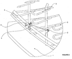
Figure 2 shows an isometric view of the tail holding apparatus attached to the stationary rail of the rotating platform shown inFigure 1 ; -
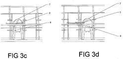
Figures 3a to 3d show a progressive sequence from the rear of an animal on a rotating milking platform in which the animal's tail is being manipulated by a tail holding apparatus; and -
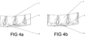
Figures 4a to 4d show a plan view of the same sequence as inFigures 3a to 3d . - The invention will be described with reference to a milking parlour using a rotary platform. However, it is to be appreciated that the tail positioning system of the invention may be applied to any desired milking configuration.
- Referring to
figure 1 &2 a milking parlour having a rotary platform (1) is shown. As illustrated, the platform (1) will rotate anti-clockwise (left-to-right) while the outer rail (4) remains stationary. Animals enter a bale on the rotary platform (1) where the bale is defined by bale separators (5) through an opening (not shown) in the stationary rail (4) that encircles the rotating platform at a predefined entry point. As the platform is rotated, the animal is moved to locations at which various tasks such as teat spraying and milk cup attachment are performed. The Tail holder (6) is fixed to the stationary rail (4) that encircles the rotating platform at a location where it is desirable not to have the animal's tail obscuring the pathway between the animal's rear legs. Alternatively it may be desirable for the hook (2) to have a limited amount of movement, for example to advance towards the animal's tail or to follow the animal's motion as it moves around part of the platform (1). The hook (2) of the tail holder (6) follows the contour of the animal's posterior as the platform (1) rotates past by moving in and out around the pivot (3). The tail of the animal is captured by the hook (2) and held in the hook (2) until the platform (1) has rotated a linear distance equal to the length of the animal's tail. As the platform (1) rotates, the animal's tail slides through the hook (2). Once the platform (1) has rotated a linear distance approximately equal to the length of the animals tail, the tail will have slid through the hook (2) completely and have been released. In the event that the tail was to become entangled in the hook (2) or was too large at some point along its length to slide through the hook (2), the hook (2) is designed with a spring release so that the animal's tail will be released and cannot be hurt. During the time the tail is held in the tail holder any operation being required on the udder can be conducted with access and vision unconstrained by the animals tail. - Referring now to
figures 3a to 3d andfigures 4a to 4d , an animal (7) is shown being transported on a rotary platform. The figures show a sequence in which the animal (7) is moving from left to right and the tail (8) is lifted by the hook (2). In the embodiment shown, the hook (2) is of an elongated configuration to lengthen the distance over which the tail (8) remains lifted. The elongated section may have any convenient form such as a trough to guide the tail (8) or a second hooking profile as shown. Infigures 3a and4a , the animal (7) is shown approaching the first hooking section of the hook (2). The tail (8) will typically be pointing downwards. Infigures 3b and4b , the tail (8) has begun to engage with the first hooking section of the hook (2) and is being pushed to the side. The rear of the animal (7) has also made contact with the hook (2) and the hook (2) is forced outwards to follow the contour of the animal's rear. Infigures 3c and4c , the tail (8) has been pushed sideways sufficiently to allow an unobstructed pathway between the rear legs of the animal (7) allowing various operations to be conducted between the animals rear legs without the influence of the tail (8).Figures 3d and4d show the tail (8) now engaging with the second hooking section of the hook (2), thus holding the tail (8) up for a further distance. Once the animal (7) has been transported far enough for the end of the tail (8) to disengage with the second hooking section of the hook (2) the tail (8) will tend to drop back down to a similar posture as shown infigure 3a . - An example (not shown) of the present disclosure may be used in a milking system such as a herringbone parlour in which the animals are stationary and the hook is actuated to engage with the tail and move it to the side.
Claims (12)
- A dairy milking system including a tail positioning apparatus and a platform (1) for supporting an animal (7), the platform being configured to move with respect to the tail positioning apparatus (6), the tail positioning apparatus (6) including a hook (2) which is configured to engage an animal's tail (8) and to move the tail (8) to one side by relative movement between an animal (7) on the platform (1) and the tail positioning apparatus (6), whereby the hook (2) is attached to a lead-in bar which is configured such that the hook follows the contour of the posterior of the animal (7) in use such that during relative movement between an animal (7) on the platform and the apparatus (6), the animal (7) and the bar rub against each other, guiding the hook (2) towards the expected location of the tail (8).
- A dairy milking system as claimed in claim 1 whereby the hook (2) has means to release the tail (8) when the tensile force between the tail (8) and the hook (2) reaches a preset limit.
- A dairy milking system as claimed in any of the above claims containing means to continue guiding the tail (8) to the side beyond a point at which the tail (8) is released from the hook (2).
- A dairy milking system as claimed in claim 3 in which the means to continue guiding the tail (8) is a trough.
- A dairy milking system as claimed in claim 3 in which the means to continue guiding the tail (8) is one or more additional hooks.
- A dairy milking system as claimed in any of the above claims in which the hook (2) is configured to advance towards the animal's tail or to follow the animal's motion as it moves around part of the platform (1).
- A method of moving an animal's tail to one side comprising moving an animal (7) on a moving platform (1) relative to a hook (2) such that the hook (2) engages and moves the animal's tail (8) to one side, whereby a lead-in bar attached to the hook (2) is held against the posterior of the animal (7) such that during relative movement between the animal (7) and the hook (2), the animal and the bar rub against each other guiding the hook (2) towards the expected location of the tail (8).
- A method of moving an animal's tail (8) to one side as claimed in claim 7 whereby the lead-in bar is held against the posterior of the animal (7) by spring force.
- A method of moving an animal's tail (8) to one side as claimed in claim 7 or claim 8 whereby the hook (2) has means to release the tail (8) when the tensile force between the tail (8) and the hook (2) reaches a preset limit.
- A method of moving an animal's tail (8) to one side as claimed in any of the above claims 7 to 9 whereby the tail (8) can be guided to the side beyond the point at which the tail (8) is released from the hook (2).
- A method of moving an animal's tail to one side as claimed in any of the above claims 7 to 10 in which the hook (2) advances towards the animal's tail or follows the animal's motion as it moves around part of the platform (1).
- A method of performing dairy milking activities in which the animal's tail is moved to one side using a method as claimed in any of claims 7 to 11.
Applications Claiming Priority (2)
| Application Number | Priority Date | Filing Date | Title |
|---|---|---|---|
| NZ60113612 | 2012-07-06 | ||
| PCT/NZ2013/000116 WO2014007662A1 (en) | 2012-07-06 | 2013-07-04 | A method and apparatus for controlling an animal's tail position |
Publications (3)
| Publication Number | Publication Date |
|---|---|
| EP2869695A1 EP2869695A1 (en) | 2015-05-13 |
| EP2869695A4 EP2869695A4 (en) | 2016-03-16 |
| EP2869695B1 true EP2869695B1 (en) | 2017-12-13 |
Family
ID=49882302
Family Applications (1)
| Application Number | Title | Priority Date | Filing Date |
|---|---|---|---|
| EP13813429.1A Not-in-force EP2869695B1 (en) | 2012-07-06 | 2013-07-04 | A method and apparatus for controlling an animal's tail position |
Country Status (6)
| Country | Link |
|---|---|
| US (1) | US9629335B2 (en) |
| EP (1) | EP2869695B1 (en) |
| AU (1) | AU2013285627B2 (en) |
| DK (1) | DK2869695T3 (en) |
| WO (1) | WO2014007662A1 (en) |
| ZA (1) | ZA201408717B (en) |
Families Citing this family (2)
| Publication number | Priority date | Publication date | Assignee | Title |
|---|---|---|---|---|
| US10051832B2 (en) | 2016-08-17 | 2018-08-21 | Technologies Holdings Corp. | Vision system with tail positioner |
| AU2017225080B2 (en) * | 2016-09-30 | 2021-09-09 | Technologies Holdings Corp. | Vision system with tail positioner |
Family Cites Families (36)
| Publication number | Priority date | Publication date | Assignee | Title |
|---|---|---|---|---|
| US255233A (en) * | 1882-03-21 | Thomas o | ||
| US711602A (en) * | 1901-03-19 | 1902-10-21 | Frank S Weed | Cow-tail holder. |
| US1044302A (en) * | 1911-06-03 | 1912-11-12 | William M Underhill | Holder for cows' tails. |
| US1179590A (en) * | 1915-06-15 | 1916-04-18 | Ralph H Whitcomb | Spring-release device. |
| US1458821A (en) * | 1921-12-02 | 1923-06-12 | Haering Joseph | Cow-tail holder |
| US1450774A (en) * | 1922-05-16 | 1923-04-03 | Haering Joseph | Cow-tail holder |
| DE520891C (en) * | 1929-09-03 | 1931-03-14 | Alois Mueller | Cow tail holder attached to the stable ceiling |
| CH154441A (en) * | 1931-03-03 | 1932-05-15 | Imhof Fritz | Cow tail holder. |
| US1867552A (en) * | 1931-08-21 | 1932-07-19 | Fotel George | Cow-tail holder |
| US1904635A (en) * | 1932-09-22 | 1933-04-18 | Ira A Trowbridge | Cow tail hanger |
| US1927119A (en) * | 1933-01-31 | 1933-09-19 | Giese Albert | Holder for cow-tails |
| CH172981A (en) * | 1934-01-03 | 1934-11-15 | Steurer Peter | Cow tail holder. |
| FR773218A (en) * | 1934-05-12 | 1934-11-14 | Cow tail holder | |
| CH185072A (en) * | 1936-01-09 | 1936-07-15 | Heusser Kaspar | Cow tail holder. |
| CH217410A (en) * | 1941-03-22 | 1941-10-31 | Griss Paul | Cow tail holder. |
| CH249301A (en) * | 1946-02-12 | 1947-06-30 | Faehndrich Jos | Device for holding a cow's tail. |
| US2645203A (en) * | 1950-06-27 | 1953-07-14 | Jaksekovich Stephen | Cowtail suspender |
| DE833876C (en) * | 1950-12-10 | 1952-07-17 | Rupert Brugger | Cow tail suspension device for the stable |
| DE947120C (en) * | 1953-12-05 | 1956-08-09 | Wilhelm Vingerhoet | Cow tail holder |
| CH323246A (en) * | 1955-11-29 | 1957-07-31 | Sommer Wilhelm | Device for holding cow tails |
| US3035546A (en) * | 1959-02-17 | 1962-05-22 | John A Peters | Cow tail guard |
| DE1216004B (en) * | 1964-06-19 | 1966-05-05 | Robert Lauber | System for keeping animals clean in cattle sheds |
| CH413481A (en) * | 1964-06-19 | 1966-05-15 | Lauber Robert | System for keeping cattle in stables clean |
| DE1810997A1 (en) * | 1968-11-26 | 1970-06-04 | Franz Wissmiller | Device for hanging the tails of cattle |
| US3962575A (en) * | 1975-02-26 | 1976-06-08 | Vandenberg Ben W | Radial arm milk hose support |
| CH595748A5 (en) * | 1976-02-10 | 1978-02-28 | Niederoest Dobler Walter | Milking parlour tail lifting cable system |
| CH594347A5 (en) * | 1976-04-27 | 1978-01-13 | Niederoest Dobler Walter | Holding device for cow tails |
| NL8304498A (en) | 1983-12-30 | 1985-07-16 | Ir Roelof Geert Middel En Rink | DEVICE FOR MILKING CATTLE AND METHOD FOR OPERATING SUCH A DEVICE |
| SU1503795A1 (en) | 1988-02-19 | 1989-08-30 | Всесоюзный Научно-Исследовательский Институт Овцеводства И Козоводства | Installation for artificial insemination of sheep |
| US5014648A (en) * | 1989-01-25 | 1991-05-14 | Frank Konitzer | Cow anti-kick apparatus, and method of use |
| US4969917A (en) | 1989-05-15 | 1990-11-13 | Gaston Poulin | Animal tail control device |
| US5086612A (en) * | 1991-02-11 | 1992-02-11 | Anderson Heather E | Tail lengthener assembly and method of use |
| DE9420782U1 (en) * | 1994-12-27 | 1995-02-09 | Tenwinkel, Margret, 48691 Vreden | Milk hose holder |
| IES20040353A2 (en) * | 2004-05-20 | 2005-11-30 | Darragh Mooney | A guard for a bovine animal's tail |
| FR2885485B1 (en) * | 2005-05-12 | 2007-07-20 | Binet Sa | MANUFACTURING OF A PASSAGE OF MAN FOR TREATING INSIDE A ROTARY CIRCULAR PLATFORM |
| EP2060172B1 (en) * | 2007-11-16 | 2014-12-17 | DeLaval Holding AB | Apparatus and method for positioning a teat cup |
-
2013
- 2013-07-04 EP EP13813429.1A patent/EP2869695B1/en not_active Not-in-force
- 2013-07-04 WO PCT/NZ2013/000116 patent/WO2014007662A1/en not_active Ceased
- 2013-07-04 US US14/412,837 patent/US9629335B2/en not_active Expired - Fee Related
- 2013-07-04 AU AU2013285627A patent/AU2013285627B2/en not_active Ceased
- 2013-07-04 DK DK13813429.1T patent/DK2869695T3/en active
-
2014
- 2014-11-26 ZA ZA2014/08717A patent/ZA201408717B/en unknown
Non-Patent Citations (1)
| Title |
|---|
| None * |
Also Published As
| Publication number | Publication date |
|---|---|
| DK2869695T3 (en) | 2018-03-26 |
| ZA201408717B (en) | 2015-12-23 |
| US9629335B2 (en) | 2017-04-25 |
| EP2869695A4 (en) | 2016-03-16 |
| AU2013285627A1 (en) | 2014-12-04 |
| AU2013285627B2 (en) | 2018-05-24 |
| WO2014007662A1 (en) | 2014-01-09 |
| US20150156986A1 (en) | 2015-06-11 |
| EP2869695A1 (en) | 2015-05-13 |
Similar Documents
| Publication | Publication Date | Title |
|---|---|---|
| CN103209585B (en) | For the milking parlour of animal | |
| US9675043B2 (en) | Rotary parlour arranged to house animals to be milked | |
| US20120272906A1 (en) | Milking Box With Robotic Attacher | |
| US20160106064A1 (en) | Tag applicator | |
| US20140041591A1 (en) | Milking Cluster and Milking Parlor Having Such a Milking Cluster | |
| EP3051955B1 (en) | A skinning device for removing skin from an animal carcass part when conveyed by a conveyor means | |
| PT1311152E (en) | ORDER AND SUPPORTING APPARATUS FOR TEETH RECEPTION | |
| WO2017051418A3 (en) | Mobile milking robot with minimal footprint configured to operate in a parallel milking parlor | |
| RU2019104786A (en) | METHOD AND SYSTEM OF MANAGEMENT OF DAIRY ANIMALS | |
| US9629335B2 (en) | Method and apparatus for controlling an animal's tail position | |
| NL1038063C2 (en) | DEVICE AND METHOD FOR SEPARATING LIGBOXES IN A WALKING STABLE. | |
| US5950561A (en) | Milking machine upright attachment and storage system | |
| EP3389365B1 (en) | Milking device | |
| NZ609164B2 (en) | A method and apparatus for controlling an animal's tail position | |
| NZ609164A (en) | A method and apparatus for controlling an animal’s tail position | |
| US9222533B2 (en) | Emergency stop device for a rotary platform of a milking parlour | |
| EP2790493B1 (en) | A rotary parlour arranged to house animals to be milked | |
| CN115697047B (en) | Milking installations and milking parlors for animals | |
| NL2015970B1 (en) | Milking establishment | |
| US20110114023A1 (en) | Method and device for treatment of animals | |
| EP2949207A2 (en) | Door for closing a space for keeping livestock and a feeding box with a door | |
| EP1505868B1 (en) | Divider for neck rail | |
| KR200477304Y1 (en) | Pet guide apparatus | |
| KR20170066811A (en) | leash device for livestock | |
| NZ757112A (en) | An expelling device and a milking arrangement provided with such a device |
Legal Events
| Date | Code | Title | Description |
|---|---|---|---|
| PUAI | Public reference made under article 153(3) epc to a published international application that has entered the european phase |
Free format text: ORIGINAL CODE: 0009012 |
|
| 17P | Request for examination filed |
Effective date: 20150129 |
|
| AK | Designated contracting states |
Kind code of ref document: A1 Designated state(s): AL AT BE BG CH CY CZ DE DK EE ES FI FR GB GR HR HU IE IS IT LI LT LU LV MC MK MT NL NO PL PT RO RS SE SI SK SM TR |
|
| AX | Request for extension of the european patent |
Extension state: BA ME |
|
| DAX | Request for extension of the european patent (deleted) | ||
| RA4 | Supplementary search report drawn up and despatched (corrected) |
Effective date: 20160216 |
|
| RIC1 | Information provided on ipc code assigned before grant |
Ipc: A01K 1/12 20060101ALI20160210BHEP Ipc: A01J 7/00 20060101ALI20160210BHEP Ipc: A01K 13/00 20060101AFI20160210BHEP |
|
| GRAP | Despatch of communication of intention to grant a patent |
Free format text: ORIGINAL CODE: EPIDOSNIGR1 |
|
| INTG | Intention to grant announced |
Effective date: 20170616 |
|
| RIN1 | Information on inventor provided before grant (corrected) |
Inventor name: WILSON, JOHN Inventor name: GLOVER, THOMAS Inventor name: WILSON, ROBERT |
|
| GRAS | Grant fee paid |
Free format text: ORIGINAL CODE: EPIDOSNIGR3 |
|
| GRAJ | Information related to disapproval of communication of intention to grant by the applicant or resumption of examination proceedings by the epo deleted |
Free format text: ORIGINAL CODE: EPIDOSDIGR1 |
|
| GRAL | Information related to payment of fee for publishing/printing deleted |
Free format text: ORIGINAL CODE: EPIDOSDIGR3 |
|
| RAP1 | Party data changed (applicant data changed or rights of an application transferred) |
Owner name: SCOTT TECHNOLOGY NZ LIMITED |
|
| GRAR | Information related to intention to grant a patent recorded |
Free format text: ORIGINAL CODE: EPIDOSNIGR71 |
|
| INTC | Intention to grant announced (deleted) | ||
| GRAA | (expected) grant |
Free format text: ORIGINAL CODE: 0009210 |
|
| INTG | Intention to grant announced |
Effective date: 20171107 |
|
| REG | Reference to a national code |
Ref country code: GB Ref legal event code: FG4D |
|
| REG | Reference to a national code |
Ref country code: AT Ref legal event code: REF Ref document number: 953477 Country of ref document: AT Kind code of ref document: T Effective date: 20171215 Ref country code: CH Ref legal event code: EP |
|
| REG | Reference to a national code |
Ref country code: IE Ref legal event code: FG4D |
|
| REG | Reference to a national code |
Ref country code: DE Ref legal event code: R096 Ref document number: 602013030858 Country of ref document: DE |
|
| REG | Reference to a national code |
Ref country code: DK Ref legal event code: T3 Effective date: 20180319 |
|
| REG | Reference to a national code |
Ref country code: SE Ref legal event code: TRGR |
|
| REG | Reference to a national code |
Ref country code: NL Ref legal event code: MP Effective date: 20171213 |
|
| PG25 | Lapsed in a contracting state [announced via postgrant information from national office to epo] |
Ref country code: FI Free format text: LAPSE BECAUSE OF FAILURE TO SUBMIT A TRANSLATION OF THE DESCRIPTION OR TO PAY THE FEE WITHIN THE PRESCRIBED TIME-LIMIT Effective date: 20171213 Ref country code: NO Free format text: LAPSE BECAUSE OF FAILURE TO SUBMIT A TRANSLATION OF THE DESCRIPTION OR TO PAY THE FEE WITHIN THE PRESCRIBED TIME-LIMIT Effective date: 20180313 |
|
| REG | Reference to a national code |
Ref country code: AT Ref legal event code: MK05 Ref document number: 953477 Country of ref document: AT Kind code of ref document: T Effective date: 20171213 |
|
| PG25 | Lapsed in a contracting state [announced via postgrant information from national office to epo] |
Ref country code: HR Free format text: LAPSE BECAUSE OF FAILURE TO SUBMIT A TRANSLATION OF THE DESCRIPTION OR TO PAY THE FEE WITHIN THE PRESCRIBED TIME-LIMIT Effective date: 20171213 Ref country code: GR Free format text: LAPSE BECAUSE OF FAILURE TO SUBMIT A TRANSLATION OF THE DESCRIPTION OR TO PAY THE FEE WITHIN THE PRESCRIBED TIME-LIMIT Effective date: 20180314 Ref country code: RS Free format text: LAPSE BECAUSE OF FAILURE TO SUBMIT A TRANSLATION OF THE DESCRIPTION OR TO PAY THE FEE WITHIN THE PRESCRIBED TIME-LIMIT Effective date: 20171213 Ref country code: LV Free format text: LAPSE BECAUSE OF FAILURE TO SUBMIT A TRANSLATION OF THE DESCRIPTION OR TO PAY THE FEE WITHIN THE PRESCRIBED TIME-LIMIT Effective date: 20171213 Ref country code: BG Free format text: LAPSE BECAUSE OF FAILURE TO SUBMIT A TRANSLATION OF THE DESCRIPTION OR TO PAY THE FEE WITHIN THE PRESCRIBED TIME-LIMIT Effective date: 20180313 |
|
| PG25 | Lapsed in a contracting state [announced via postgrant information from national office to epo] |
Ref country code: NL Free format text: LAPSE BECAUSE OF FAILURE TO SUBMIT A TRANSLATION OF THE DESCRIPTION OR TO PAY THE FEE WITHIN THE PRESCRIBED TIME-LIMIT Effective date: 20171213 |
|
| REG | Reference to a national code |
Ref country code: FR Ref legal event code: PLFP Year of fee payment: 6 |
|
| PG25 | Lapsed in a contracting state [announced via postgrant information from national office to epo] |
Ref country code: EE Free format text: LAPSE BECAUSE OF FAILURE TO SUBMIT A TRANSLATION OF THE DESCRIPTION OR TO PAY THE FEE WITHIN THE PRESCRIBED TIME-LIMIT Effective date: 20171213 Ref country code: SK Free format text: LAPSE BECAUSE OF FAILURE TO SUBMIT A TRANSLATION OF THE DESCRIPTION OR TO PAY THE FEE WITHIN THE PRESCRIBED TIME-LIMIT Effective date: 20171213 Ref country code: ES Free format text: LAPSE BECAUSE OF FAILURE TO SUBMIT A TRANSLATION OF THE DESCRIPTION OR TO PAY THE FEE WITHIN THE PRESCRIBED TIME-LIMIT Effective date: 20171213 Ref country code: CZ Free format text: LAPSE BECAUSE OF FAILURE TO SUBMIT A TRANSLATION OF THE DESCRIPTION OR TO PAY THE FEE WITHIN THE PRESCRIBED TIME-LIMIT Effective date: 20171213 Ref country code: CY Free format text: LAPSE BECAUSE OF FAILURE TO SUBMIT A TRANSLATION OF THE DESCRIPTION OR TO PAY THE FEE WITHIN THE PRESCRIBED TIME-LIMIT Effective date: 20171213 |
|
| PG25 | Lapsed in a contracting state [announced via postgrant information from national office to epo] |
Ref country code: SM Free format text: LAPSE BECAUSE OF FAILURE TO SUBMIT A TRANSLATION OF THE DESCRIPTION OR TO PAY THE FEE WITHIN THE PRESCRIBED TIME-LIMIT Effective date: 20171213 Ref country code: PL Free format text: LAPSE BECAUSE OF FAILURE TO SUBMIT A TRANSLATION OF THE DESCRIPTION OR TO PAY THE FEE WITHIN THE PRESCRIBED TIME-LIMIT Effective date: 20171213 Ref country code: IT Free format text: LAPSE BECAUSE OF FAILURE TO SUBMIT A TRANSLATION OF THE DESCRIPTION OR TO PAY THE FEE WITHIN THE PRESCRIBED TIME-LIMIT Effective date: 20171213 Ref country code: AT Free format text: LAPSE BECAUSE OF FAILURE TO SUBMIT A TRANSLATION OF THE DESCRIPTION OR TO PAY THE FEE WITHIN THE PRESCRIBED TIME-LIMIT Effective date: 20171213 Ref country code: IS Free format text: LAPSE BECAUSE OF FAILURE TO SUBMIT A TRANSLATION OF THE DESCRIPTION OR TO PAY THE FEE WITHIN THE PRESCRIBED TIME-LIMIT Effective date: 20180413 Ref country code: RO Free format text: LAPSE BECAUSE OF FAILURE TO SUBMIT A TRANSLATION OF THE DESCRIPTION OR TO PAY THE FEE WITHIN THE PRESCRIBED TIME-LIMIT Effective date: 20171213 |
|
| REG | Reference to a national code |
Ref country code: DE Ref legal event code: R097 Ref document number: 602013030858 Country of ref document: DE |
|
| PLBE | No opposition filed within time limit |
Free format text: ORIGINAL CODE: 0009261 |
|
| STAA | Information on the status of an ep patent application or granted ep patent |
Free format text: STATUS: NO OPPOSITION FILED WITHIN TIME LIMIT |
|
| 26N | No opposition filed |
Effective date: 20180914 |
|
| PG25 | Lapsed in a contracting state [announced via postgrant information from national office to epo] |
Ref country code: SI Free format text: LAPSE BECAUSE OF FAILURE TO SUBMIT A TRANSLATION OF THE DESCRIPTION OR TO PAY THE FEE WITHIN THE PRESCRIBED TIME-LIMIT Effective date: 20171213 |
|
| REG | Reference to a national code |
Ref country code: CH Ref legal event code: PL |
|
| PG25 | Lapsed in a contracting state [announced via postgrant information from national office to epo] |
Ref country code: LU Free format text: LAPSE BECAUSE OF NON-PAYMENT OF DUE FEES Effective date: 20180704 Ref country code: MC Free format text: LAPSE BECAUSE OF FAILURE TO SUBMIT A TRANSLATION OF THE DESCRIPTION OR TO PAY THE FEE WITHIN THE PRESCRIBED TIME-LIMIT Effective date: 20171213 |
|
| REG | Reference to a national code |
Ref country code: BE Ref legal event code: MM Effective date: 20180731 |
|
| PG25 | Lapsed in a contracting state [announced via postgrant information from national office to epo] |
Ref country code: LI Free format text: LAPSE BECAUSE OF NON-PAYMENT OF DUE FEES Effective date: 20180731 Ref country code: CH Free format text: LAPSE BECAUSE OF NON-PAYMENT OF DUE FEES Effective date: 20180731 |
|
| PG25 | Lapsed in a contracting state [announced via postgrant information from national office to epo] |
Ref country code: BE Free format text: LAPSE BECAUSE OF NON-PAYMENT OF DUE FEES Effective date: 20180731 |
|
| PGFP | Annual fee paid to national office [announced via postgrant information from national office to epo] |
Ref country code: SE Payment date: 20190719 Year of fee payment: 7 Ref country code: FR Payment date: 20190719 Year of fee payment: 7 Ref country code: IE Payment date: 20190724 Year of fee payment: 7 Ref country code: DK Payment date: 20190723 Year of fee payment: 7 Ref country code: DE Payment date: 20190719 Year of fee payment: 7 |
|
| PGFP | Annual fee paid to national office [announced via postgrant information from national office to epo] |
Ref country code: GB Payment date: 20190719 Year of fee payment: 7 |
|
| PG25 | Lapsed in a contracting state [announced via postgrant information from national office to epo] |
Ref country code: MT Free format text: LAPSE BECAUSE OF NON-PAYMENT OF DUE FEES Effective date: 20180704 |
|
| PG25 | Lapsed in a contracting state [announced via postgrant information from national office to epo] |
Ref country code: TR Free format text: LAPSE BECAUSE OF FAILURE TO SUBMIT A TRANSLATION OF THE DESCRIPTION OR TO PAY THE FEE WITHIN THE PRESCRIBED TIME-LIMIT Effective date: 20171213 |
|
| PG25 | Lapsed in a contracting state [announced via postgrant information from national office to epo] |
Ref country code: PT Free format text: LAPSE BECAUSE OF FAILURE TO SUBMIT A TRANSLATION OF THE DESCRIPTION OR TO PAY THE FEE WITHIN THE PRESCRIBED TIME-LIMIT Effective date: 20171213 Ref country code: HU Free format text: LAPSE BECAUSE OF FAILURE TO SUBMIT A TRANSLATION OF THE DESCRIPTION OR TO PAY THE FEE WITHIN THE PRESCRIBED TIME-LIMIT; INVALID AB INITIO Effective date: 20130704 |
|
| PG25 | Lapsed in a contracting state [announced via postgrant information from national office to epo] |
Ref country code: LT Free format text: LAPSE BECAUSE OF FAILURE TO SUBMIT A TRANSLATION OF THE DESCRIPTION OR TO PAY THE FEE WITHIN THE PRESCRIBED TIME-LIMIT Effective date: 20171213 Ref country code: MK Free format text: LAPSE BECAUSE OF NON-PAYMENT OF DUE FEES Effective date: 20171213 |
|
| PG25 | Lapsed in a contracting state [announced via postgrant information from national office to epo] |
Ref country code: AL Free format text: LAPSE BECAUSE OF FAILURE TO SUBMIT A TRANSLATION OF THE DESCRIPTION OR TO PAY THE FEE WITHIN THE PRESCRIBED TIME-LIMIT Effective date: 20171213 |
|
| REG | Reference to a national code |
Ref country code: DE Ref legal event code: R119 Ref document number: 602013030858 Country of ref document: DE |
|
| REG | Reference to a national code |
Ref country code: DK Ref legal event code: EBP Effective date: 20200731 |
|
| REG | Reference to a national code |
Ref country code: SE Ref legal event code: EUG |
|
| GBPC | Gb: european patent ceased through non-payment of renewal fee |
Effective date: 20200704 |
|
| PG25 | Lapsed in a contracting state [announced via postgrant information from national office to epo] |
Ref country code: IE Free format text: LAPSE BECAUSE OF NON-PAYMENT OF DUE FEES Effective date: 20200704 Ref country code: GB Free format text: LAPSE BECAUSE OF NON-PAYMENT OF DUE FEES Effective date: 20200704 Ref country code: FR Free format text: LAPSE BECAUSE OF NON-PAYMENT OF DUE FEES Effective date: 20200731 |
|
| PG25 | Lapsed in a contracting state [announced via postgrant information from national office to epo] |
Ref country code: DE Free format text: LAPSE BECAUSE OF NON-PAYMENT OF DUE FEES Effective date: 20210202 Ref country code: SE Free format text: LAPSE BECAUSE OF NON-PAYMENT OF DUE FEES Effective date: 20200705 |
|
| PG25 | Lapsed in a contracting state [announced via postgrant information from national office to epo] |
Ref country code: DK Free format text: LAPSE BECAUSE OF NON-PAYMENT OF DUE FEES Effective date: 20200731 |