EP2869471A1 - Coding and decoding of runlength limited error correcting codes based on Hamming codes - Google Patents
Coding and decoding of runlength limited error correcting codes based on Hamming codes Download PDFInfo
- Publication number
- EP2869471A1 EP2869471A1 EP20140189177 EP14189177A EP2869471A1 EP 2869471 A1 EP2869471 A1 EP 2869471A1 EP 20140189177 EP20140189177 EP 20140189177 EP 14189177 A EP14189177 A EP 14189177A EP 2869471 A1 EP2869471 A1 EP 2869471A1
- Authority
- EP
- European Patent Office
- Prior art keywords
- bits
- parity
- coded
- data
- hamming
- Prior art date
- Legal status (The legal status is an assumption and is not a legal conclusion. Google has not performed a legal analysis and makes no representation as to the accuracy of the status listed.)
- Ceased
Links
Images


Classifications
-
- G—PHYSICS
- G06—COMPUTING OR CALCULATING; COUNTING
- G06F—ELECTRIC DIGITAL DATA PROCESSING
- G06F11/00—Error detection; Error correction; Monitoring
- G06F11/07—Responding to the occurrence of a fault, e.g. fault tolerance
- G06F11/08—Error detection or correction by redundancy in data representation, e.g. by using checking codes
- G06F11/10—Adding special bits or symbols to the coded information, e.g. parity check, casting out 9's or 11's
-
- H—ELECTRICITY
- H03—ELECTRONIC CIRCUITRY
- H03M—CODING; DECODING; CODE CONVERSION IN GENERAL
- H03M13/00—Coding, decoding or code conversion, for error detection or error correction; Coding theory basic assumptions; Coding bounds; Error probability evaluation methods; Channel models; Simulation or testing of codes
- H03M13/03—Error detection or forward error correction by redundancy in data representation, i.e. code words containing more digits than the source words
- H03M13/05—Error detection or forward error correction by redundancy in data representation, i.e. code words containing more digits than the source words using block codes, i.e. a predetermined number of check bits joined to a predetermined number of information bits
- H03M13/13—Linear codes
- H03M13/19—Single error correction without using particular properties of the cyclic codes, e.g. Hamming codes, extended or generalised Hamming codes
-
- H—ELECTRICITY
- H03—ELECTRONIC CIRCUITRY
- H03M—CODING; DECODING; CODE CONVERSION IN GENERAL
- H03M13/00—Coding, decoding or code conversion, for error detection or error correction; Coding theory basic assumptions; Coding bounds; Error probability evaluation methods; Channel models; Simulation or testing of codes
- H03M13/31—Coding, decoding or code conversion, for error detection or error correction; Coding theory basic assumptions; Coding bounds; Error probability evaluation methods; Channel models; Simulation or testing of codes combining coding for error detection or correction and efficient use of the spectrum
Definitions
- HC Hamming codes
- a Hamming code provides error detection and correction for a plurality of data bits by including a plurality of parity bits, where the parity bits are intermingled among the data bits.
- communications between a sender and a receiver may be synchronized using a clock recovery or clock-data recovery (CDR) process.
- CDR clock-data recovery
- a receiver may generate a clock from an approximate frequency reference using a phase-locked loop (PLL), and then phase-align the generated signal to the transitions in the data stream using CDR.
- PLL phase-locked loop
- recovery of the clock signal can fail if the data run length (e.g., stream of consecutive 1s or 0s) exceeds a particular length due to there being an insufficient number of transitions for the receiver to detect.
- aspects of embodiments of the present invention are directed to systems and methods for reducing or minimizing the run length of digital data.
- a modified Hamming encoding operation is applied to the digital data.
- a method for encoding data includes: computing a plurality of parity bits using a Hamming encoding operation on a plurality of data bits, a first parity bit of the parity bits being computed using even parity and a second parity bit of the parity bits being computed using odd parity; and outputting the data bits and the computed parity bits.
- the second parity bit may be the last parity bit in sequence of the plurality of parity bits.
- the first parity bit may be the second to the last parity bit in sequence of the plurality of parity bits.
- the Hamming encoding operation may correspond to HC(127, 120), the first parity bit may be the 6th parity bit and the second parity bit may be the 7th parity bit.
- a method for encoding data includes: computing a plurality of parity bits utilizing a Hamming encoding operation on a plurality of data bits; interleaving the computed parity bits with the plurality of data bits to generate a plurality of coded data bits; and rearranging the plurality of coded data bits to reduce a maximum run length of a data sequence of the plurality of data bits.
- the rearranging the plurality of coded data bits may include moving a number of the plurality of coded data bits at the beginning of the coded data bits to a position after a last one of the coded data bits.
- the Hamming encoding operation may correspond to HC(127, 120), and the number of the plurality of coded data bits at the beginning may include 32 bits.
- the Hamming encoding operation may utilize odd parity.
- an encoder includes: an input configured to receive a plurality of data bits; a processor configured to encode the data bits utilizing a Hamming encoding operation to generate a plurality of coded bits; and an output configured to output the plurality of coded bits, wherein the processor is configured to reduce a maximum run length of the plurality of coded bits in comparison to coded bits corresponding to standard Hamming code.
- the processor may be configured to compute a plurality of parity bits utilizing the Hamming encoding operation on the plurality of data bits, a first parity bit of the parity bits being computed utilizing even parity and a second parity bit of the parity bits being computed utilizing odd parity, wherein the plurality of coded bits may include the data bits and the computed parity bits.
- the processor may be configured to rearrange the plurality of coded bits to reduce the maximum run length of the plurality of coded bits.
- the plurality of coded bits may be rearranged by moving a number of the plurality of coded bits at the beginning to a position after a last one of the coded bits.
- the Hamming encoding operation may correspond to HC(127, 120), and the number of the plurality of coded bits at the beginning comprises 32 bits.
- a decoder includes: an input configured to receive a plurality of coded bits comprising a plurality of data bits and a plurality of parity bits; a processor configured to: modify received coded bits to generate a plurality of Hamming coded bits; and decode the Hamming coded bits utilizing a Hamming decoding operation to generate a plurality of decoded bits; and an output configured to output the plurality of decoded bits, wherein the received plurality of coded bits has a reduced run length in comparison to coded bits corresponding to standard Hamming code.
- the processor may be configured to modify the received coded bits by rearranging the plurality of received coded bits by moving a number of the plurality of coded bits at the beginning to a position after a last one of the coded bits.
- the processor may be configured to modify the received coded bits by toggling the value of a parity bit of the parity bits.
- a communication system includes: a data source; a serial link; an encoder coupled between the data source and the serial link, the encoder including: an input configured to receive a plurality of bits from the data source; a processor configured to encode the bits utilizing a Hamming encoding operation to generate a plurality of coded bits; and an output configured to output the plurality of coded bits to the serial link, wherein the processor is configured to reduce a maximum run length of the plurality of coded bits in comparison to coded bits corresponding to standard Hamming code.
- the processor may be configured to compute a plurality of parity bits utilizing the Hamming encoding operation on the plurality of bits, a first parity bit of the parity bits being computed utilizing even parity and a second parity bit of the parity bits being computed utilizing odd parity, wherein the plurality of coded bits comprises the data bits and the computed parity bits.
- the processor may be configured to rearrange the plurality of coded bits to reduce the maximum run length of the plurality of coded bits by moving a number of the plurality of coded bits at the beginning to a position after a last one of the coded bits.
- aspects of embodiments of the present invention are directed to systems and methods for reducing or minimizing the run length of digital data in a communications system.
- a sender and a receiver can be synchronized using a clock recovery or clock-data recovery (CDR) process.
- CDR clock-data recovery
- a receiver using a CDR process typically operates by detecting the time of transitions between voltage levels and phase-aligning the clock of the receiver based on the detected transitions.
- the CDR process can fail due to there being an insufficient number of transitions in the received signal, which can cause problems in the recovery of the clock.
- HC Hamming Code
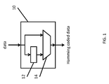
- FIG. 1 is a schematic block diagram illustrating a device 10 configured to compute Hamming codes.
- the device 10 includes a parity generator 12 and a multiplexer 14 that are configured to receive data bits via an input coupled to a data source.
- the parity generator 12 computes parity bits using a Hamming encoding operation on the data bits, and the multiplexer 14 combines the generated parity bits with the received data bits to generate Hamming coded data.
- the parity generator 12 may be an even parity generator or may be an odd parity generator.
- the multiplexer 14 may be, for example, a buffer configured to store the generated parity bits and the data bits before outputting the Hamming coded data to an output (e.g., a serial communications device coupled to a serial link).
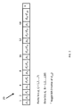
- FIG. 2 illustrates the encoding of one hundred twenty data bits through seven parity bits (referred to as HC(127, 120)).
- the parity bits are located at positions that are powers of two.
- the parity bits are located at positions 1, 2, 4, 8, 16, 32, and 64 in the standard (127, 120) Hamming code 20.
- each of the parity bits is computed based on an XOR operation on a particular set of the data bits.
- p 1 can be computed from an XOR operation on every other bit in the bit stream as follows.
- p 1 ⁇ d 1 ⁇ d 2 ⁇ d 4 ⁇ d 5 ⁇ d 7 ... f
- ⁇ is the XOR operation and f is 0 for even parity and 1 for odd parity.
- p 2 a similar XOR operation is performed by keeping two bits and dropping two bits as follows.
- p 2 ⁇ d 1 ⁇ d 3 ⁇ d 4 ⁇ d 6 ⁇ d 7 ... f
- Other parity bits are found in similar fashion.
- transmissions of data encoded with a Hamming code can result in long runs.
- Embodiments of the present invention are directed to systems and methods using a modified error correction system based on a modified Hamming code (HC) in which the number of transitions in the output of the transmitter is increased or maximized (e.g., in which the maximum run length of data symbols is reduced).
- HC modified Hamming code
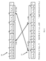
- FIG. 3 is a schematic illustration of generating modified output coded bits 22 of HC(127, 120) coded bits in accordance with one embodiment of the present invention.
- the run length can be reduced by rearranging the original coded bits.
- the parity bits can be computed in HC(127, 120) the usual way to generate coded bits 20.
- the toggle bit is at the last location.
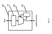
- FIG. 4 is a schematic block diagram illustrating an encoding system or transmitting system (or transmitter) 100 configured to reduce the run length of transmitted data according to one embodiment of the present invention.
- a Hamming coder 10 e.g., a suitable
- the selector 104 may include a counter to count the number of bits received from the Hamming coder 10 (or count a number of clock cycles) to determine when to save output bits in buffer 102 (e.g., the first 32 bits in HC(127, 120)), when to directly output the bits received from the Hamming coder 10 (e.g., the next 95 bits in HC(127, 120)), and when to output the stored bits (e.g., after outputting the 95 bits in HC(127, 120)).
- the various components of the block diagram of FIG. 4 may be implemented using, for example, a processor, an application specific integrated circuit (ASIC), a field programmable gate array (FPGA), and combinations thereof (e.g., different types of components implementing different parts of the block diagram).
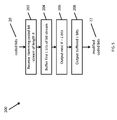
- FIG. 5 is a flow chart illustrating a method 200 for generating modified coded bits 22 from coded bits 20 according to one embodiment of the present invention, the modified coded bits 22 having a reduced run length.
- the Hamming coded bits 20 having length K are received from the Hamming coder 10, which performed a Hamming encoding operation on received data bits.
- the first L bits of the coded bits 20 are then buffered in the buffer 102 in operation 204.
- the next K - L bits of the coded bits 20 are then output as the first part of the modified coded bits 22, and, in operation 208, the L buffered bits are output as the second part of modified coded bits 22.
- the bits may be directly output or may be output to a second buffer before being output from the transmitter 100.
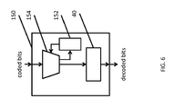
- FIG. 6 is a block diagram illustrating a receiving system (or a receiver) 150 according to one embodiment of the present invention.
- the receiver 150 includes a selector 154 for identifying which bits to store in a buffer 152 and configured to output bits to a Hamming decoder 40, where the Hamming decoder 40 outputs decoded data.
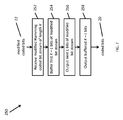
- FIG. 7 is a flowchart illustrating a method 250 for receiving and decoding modified coded bits 22 to recover original coded bits 20 according to one embodiment of the present invention.
- the modified coded bits of length K is received.
- the first K - L bits of the received modified coded bits are buffered in the buffer 152.
- the next L bits of the received modified coded bits are then output in operation 256, followed by the buffered K - L bits in operation 258.
- the output bits may be buffered before being supplied to the Hamming decoder 40 to perform a Hamming decoding operation.
- the maximum run length is reduced or minimized by using different parity types (e.g., odd versus even) for the last two parity bits.
- parity types e.g., odd versus even
- the last (or ultimate) parity bit p M of the sequence of parity bits is computed using a first parity and the second to last (or penultimate) parity bit p M -1 of the sequence of parity bits is computed using a second parity different from the first parity.
- p 6 XOR( d 27 : d 57 , d 89 : d 120 ) ⁇ 1).
- the other parity bits p 1 to p M -2 (e.g., p 1 to p 5 ) of the sequence of parity bits may have even parity or odd parity.
- Different parity bits of parity bits p 1 to p M -2 may be computed with different (even or odd) parity.
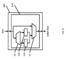
- FIG. 9 is a schematic block diagram illustrating a transmitter 300 configured to output modified Hamming coded bits 24 or 26 according to one embodiment of the present invention.
- the system 300 includes a modified Hamming coder 310 configured to compute a modified Hamming code, the modified Hamming coder 310 including a parity selector 16, a first parity generator 12a, second parity generator 12b, and a multiplexer 14.
- the first parity generator and the second parity generator are configured to compute even parity and odd parity (or perform a Hamming encoding operation), respectively.
- the parity selector 16 identifies and supplies data bits of the input data to the first parity generator and the second parity generator in accordance with the data bits needed to calculate particular parity bits.
- the parity selector 16 supplies data bits d 58 : d 120 to the second parity generator 12b (which is configured to compute odd parity) for computing p 7 and supplies data bits d 27 : d 57 and d 89 : d 120 to the first parity generator 12a to compute parity bit p 6 .
- FIG. 10 is a flow chart illustrating a method for computing modified Hamming coded bits from input data.
- data 20 is received (e.g., from a device or a component outputting data to be sent over a serial link).
- groups of bits are identified for computing the parity bits. For example, in HC(127, 120), bits d 58 : d 120 are identified as being associated with the parity bit p 7 and data bits d 27 : d 57 and d 89 : d 120 are identified as being used to compute the parity bit p 6 .
- the parity of the particular parity bit being computed is identified as being even or odd.
- p 6 is computed using even parity and p 7 is computed using odd parity.
- the data bits corresponding to that parity bit are computed using even parity in operation 408 or odd parity in operation 410.
- data bits d 27 : d 57 and d 89 : d 120 are used to compute the value of the parity bit p 6 in operation 408.
- the computed parity bits are combined (or interleaved) with the data bits 20 in the output modified Hamming coded bits 24 or 26 (e.g., parity bit p a is located at position 2 a-1 ).
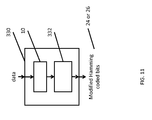
- FIG. 11 is a schematic block diagram illustrating a transmitter 330 configured to output modified Hamming coded bits 24 or 26 according to another embodiment of the present invention.
- the system 330 includes a standard Hamming coder 10 configured to compute a standard Hamming encoding operation (e.g., compute a set of M parity bits p given a set of input data bits d ), in which the last two parity bits p M -1 and p M are computed using the same parity (e.g., both are computed using even parity or both are computed using odd parity).
- a standard Hamming coder 10 configured to compute a standard Hamming encoding operation (e.g., compute a set of M parity bits p given a set of input data bits d ), in which the last two parity bits p M -1 and p M are computed using the same parity (e.g., both are computed using even parity or both are computed using odd parity).
- the system 330 further includes a parity bit modifier 332 (or transmit parity bit modifier), which is configured to modify the parity of the penultimate parity bit p M -1 (e.g., from even to odd or from odd to even) by computing the XOR of p M -1 and 1 (e.g., setting the penultimate parity bit to p M -1 ⁇ 1).
- the modified bit stream is then output as modified Hamming coded bits 24 or 26.
- the parity bit modifier 332 is configured to modify the parity of the ultimate parity bit p M by computing the XOR of p M and 1 (e.g., setting the ultimate parity bit to p M ⁇ 1).
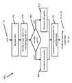
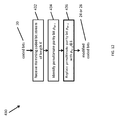
- FIG. 12 is a flow chart illustrating a method 430 for computing modified Hamming coded bits from input data according to another embodiment of the present invention.
- a Hamming coded bit stream of length K including M parity bits p and N data bits d is received.
- the penultimate parity bit p M -1 is identified, and, in operation 436, the penultimate parity bit p M -1 is inverted or replaced with p M -1 ⁇ 1 (in other words, its value is toggled or inverted from 0 to 1 or from 1 to 0).
- the modified Hamming coded bits with the inverted penultimate parity bit is then output as modified coded bits 24 or 26.
- the ultimate parity bit p M is identified, and, in operation 436, the ultimate parity bit p M is inverted or replaced with p M ⁇ 1.
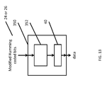
- FIG. 13 is a block diagram illustrating a receiver according to one embodiment of the present invention.
- the receive system 350 includes a receive parity bit modifier 352 configured to modify the parity of the penultimate parity bit p M -1 (e.g., from even to odd or from odd to even) by computing the XOR of p M -1 and 1 (e.g., setting the penultimate parity bit to p M- 1 ⁇ 1).
- the receive parity bit modifier 352 then supplies the bit stream to a standard Hamming decoder 40, which decodes the stream to generate decoded data.
- the ultimate parity p M is inverted instead of the penultimate parity bit p M -1 .
- FIG. 14 is a flowchart illustrating a method 450 for decoding bits in a modified Hamming code according to one embodiment of the present invention.
- a modified Hamming coded bit stream of length K is received.
- the penultimate parity bit p M -1 is identified in operation 454 and is inverted or replaced with the value of the XOR of p M -1 and 1 (e.g., setting the penultimate parity bit to p M -1 ⁇ 1) in operation 456.
- the result of this operation is to restore a standard Hamming coded bit stream 24 or 26 that can be supplied to a standard Hamming decoder.
- the ultimate parity p M is modified instead of the penultimate parity bit p M -1 .
- a reduction of run length can be achieved by mixing odd and even parities.
- Mixing odd and even parities in a Hamming encoder increases the number of transitions in the frame (or equivalently reduce the run length which is harmful for the Clock Data Recovery (CDR) operation).
- CDR Clock Data Recovery
- location 64 breaks the run and so no run bit of length 94 is possible in category (1).
- Embodiments of the present invention can be implemented in a variety of ways as would be appreciated by a person of ordinary skill in the art, and the term "processor” as used herein may refer to any computing device capable of performing the described operations, such as a programmed general purpose processor (e.g., an ARM processor) with instructions stored in memory connected to the general purpose processor, a field programmable gate array (FPGA), and a custom application specific integrated circuit (ASIC).
- a serial communications controller e.g., a universal serial bus or USB controller
- GPU graphical processing unit
Landscapes
- Engineering & Computer Science (AREA)
- Theoretical Computer Science (AREA)
- Physics & Mathematics (AREA)
- Probability & Statistics with Applications (AREA)
- Quality & Reliability (AREA)
- General Engineering & Computer Science (AREA)
- General Physics & Mathematics (AREA)
- Error Detection And Correction (AREA)
- Detection And Prevention Of Errors In Transmission (AREA)
Abstract
Description
- This application claims priority to
U.S. Provisional Patent Application No. 61/898,415 - In data communications, transmissions between a sender and a receiver can be verified and corrected using Hamming codes (HC). Generally speaking, a Hamming code provides error detection and correction for a plurality of data bits by including a plurality of parity bits, where the parity bits are intermingled among the data bits.
- In addition, in electronic data communications such as in a serial data link, communications between a sender and a receiver may be synchronized using a clock recovery or clock-data recovery (CDR) process. For example, a receiver may generate a clock from an approximate frequency reference using a phase-locked loop (PLL), and then phase-align the generated signal to the transitions in the data stream using CDR. However, recovery of the clock signal can fail if the data run length (e.g., stream of consecutive 1s or 0s) exceeds a particular length due to there being an insufficient number of transitions for the receiver to detect.
- Aspects of embodiments of the present invention are directed to systems and methods for reducing or minimizing the run length of digital data. In some embodiments, a modified Hamming encoding operation is applied to the digital data.
- According to one embodiment of the present invention, a method for encoding data includes: computing a plurality of parity bits using a Hamming encoding operation on a plurality of data bits, a first parity bit of the parity bits being computed using even parity and a second parity bit of the parity bits being computed using odd parity; and outputting the data bits and the computed parity bits.
- The second parity bit may be the last parity bit in sequence of the plurality of parity bits.
- The first parity bit may be the second to the last parity bit in sequence of the plurality of parity bits.
- The Hamming encoding operation may correspond to HC(127, 120), the first parity bit may be the 6th parity bit and the second parity bit may be the 7th parity bit.
- According to one embodiment of the present invention, a method for encoding data includes: computing a plurality of parity bits utilizing a Hamming encoding operation on a plurality of data bits; interleaving the computed parity bits with the plurality of data bits to generate a plurality of coded data bits; and rearranging the plurality of coded data bits to reduce a maximum run length of a data sequence of the plurality of data bits.
- The rearranging the plurality of coded data bits may include moving a number of the plurality of coded data bits at the beginning of the coded data bits to a position after a last one of the coded data bits.
- The Hamming encoding operation may correspond to HC(127, 120), and the number of the plurality of coded data bits at the beginning may include 32 bits.
- The Hamming encoding operation may utilize odd parity.
- According to one embodiment of the present invention, an encoder includes: an input configured to receive a plurality of data bits; a processor configured to encode the data bits utilizing a Hamming encoding operation to generate a plurality of coded bits; and an output configured to output the plurality of coded bits, wherein the processor is configured to reduce a maximum run length of the plurality of coded bits in comparison to coded bits corresponding to standard Hamming code.
- The processor may be configured to compute a plurality of parity bits utilizing the Hamming encoding operation on the plurality of data bits, a first parity bit of the parity bits being computed utilizing even parity and a second parity bit of the parity bits being computed utilizing odd parity, wherein the plurality of coded bits may include the data bits and the computed parity bits.
- The processor may be configured to rearrange the plurality of coded bits to reduce the maximum run length of the plurality of coded bits.
- The plurality of coded bits may be rearranged by moving a number of the plurality of coded bits at the beginning to a position after a last one of the coded bits.
- The Hamming encoding operation may correspond to HC(127, 120), and the number of the plurality of coded bits at the beginning comprises 32 bits.
- According to one embodiment of the present invention, a decoder includes: an input configured to receive a plurality of coded bits comprising a plurality of data bits and a plurality of parity bits; a processor configured to: modify received coded bits to generate a plurality of Hamming coded bits; and decode the Hamming coded bits utilizing a Hamming decoding operation to generate a plurality of decoded bits; and an output configured to output the plurality of decoded bits, wherein the received plurality of coded bits has a reduced run length in comparison to coded bits corresponding to standard Hamming code.
- The processor may be configured to modify the received coded bits by rearranging the plurality of received coded bits by moving a number of the plurality of coded bits at the beginning to a position after a last one of the coded bits.
- The processor may be configured to modify the received coded bits by toggling the value of a parity bit of the parity bits.
- According to one embodiment of the present invention, a communication system includes: a data source; a serial link; an encoder coupled between the data source and the serial link, the encoder including: an input configured to receive a plurality of bits from the data source; a processor configured to encode the bits utilizing a Hamming encoding operation to generate a plurality of coded bits; and an output configured to output the plurality of coded bits to the serial link, wherein the processor is configured to reduce a maximum run length of the plurality of coded bits in comparison to coded bits corresponding to standard Hamming code.
- The processor may be configured to compute a plurality of parity bits utilizing the Hamming encoding operation on the plurality of bits, a first parity bit of the parity bits being computed utilizing even parity and a second parity bit of the parity bits being computed utilizing odd parity, wherein the plurality of coded bits comprises the data bits and the computed parity bits.
- The processor may be configured to rearrange the plurality of coded bits to reduce the maximum run length of the plurality of coded bits by moving a number of the plurality of coded bits at the beginning to a position after a last one of the coded bits.
- The accompanying drawings, together with the specification, illustrate example embodiments of the present invention, and, together with the description, serve to explain the principles of the present invention.
-
FIG. 1 is a schematic block diagram illustrating a component configured to receive input data and to generate Hamming coded data. -
FIG. 2 schematically illustrates Hamming 120 data bits with 7 parity bits (or HC(127, 120). -
FIG. 3 schematically illustrates data encoded using a modified Hamming code according to one embodiment of the present invention. -
FIG. 4 is a block diagram illustrating a system configured to encode data using a modified Hamming code according to one embodiment of the present invention. -
FIG. 5 is a flowchart of a method for encoding data according to one embodiment of the present invention. -
FIG. 6 is a block diagram illustrating a system configured to decode data using a modified Hamming code according to one embodiment of the present invention. -
FIG. 7 is a flowchart of a method for decoding data according to one embodiment of the present invention. -
FIGS. 8A and 8B schematically illustrate data encoded using a modified Hamming code according to additional embodiments of the present invention. -
FIG. 9 is a block diagram illustrating a system configured to encode data using a modified hamming code according to an additional embodiment of the present invention. -
FIG. 10 is a flowchart of a method for encoding data according to another embodiment of the present invention. -
FIG. 11 is a schematic block diagram illustrating a transmitter configured to output modified Hamming coded bits according to one embodiment of the present invention. -
FIG. 12 is a flow chart illustrating a method for computing modified Hamming coded bits from input data according to one embodiment of the present invention. -
FIG. 13 is a block diagram illustrating a receiver configured to receive modified Hamming coded bits according to one embodiment of the present invention. -
FIG. 14 is a flowchart illustrating a method for decoding bits in a modified Hamming code according to one embodiment of the present invention. - In the following detailed description, only certain example embodiments of the present invention are shown and described, by way of illustration. As those skilled in the art would recognize, the invention may be embodied in many different forms and should not be construed as being limited to the embodiments set forth herein. Like reference numerals designate like elements throughout the specification.
- Aspects of embodiments of the present invention are directed to systems and methods for reducing or minimizing the run length of digital data in a communications system.
- In digital communications, a sender and a receiver can be synchronized using a clock recovery or clock-data recovery (CDR) process. A receiver using a CDR process typically operates by detecting the time of transitions between voltage levels and phase-aligning the clock of the receiver based on the detected transitions.
- However, if the received signal contains an excessively long run length (e.g., a long sequence of data symbols having the same voltage level), the CDR process can fail due to there being an insufficient number of transitions in the received signal, which can cause problems in the recovery of the clock.
- In addition, in data communications in general, errors in transmissions between a sender and a receiver can be detected and corrected by coding the bit stream. One such coding technique is called Hamming Code (HC) which provides one bit error detection and correction for a plurality of data bits by including (or interleaving) a plurality of parity bits in the communication stream. In a standard Hamming code system, these parity bits are intermingled among the data bits.
-
FIG. 1 is a schematic block diagram illustrating adevice 10 configured to compute Hamming codes. Thedevice 10 includes aparity generator 12 and amultiplexer 14 that are configured to receive data bits via an input coupled to a data source. Theparity generator 12 computes parity bits using a Hamming encoding operation on the data bits, and themultiplexer 14 combines the generated parity bits with the received data bits to generate Hamming coded data. Theparity generator 12 may be an even parity generator or may be an odd parity generator. Themultiplexer 14 may be, for example, a buffer configured to store the generated parity bits and the data bits before outputting the Hamming coded data to an output (e.g., a serial communications device coupled to a serial link). - The number of parity bits (M) depends on the number of data bits (N) in the bit stream. Specifically for N data bits, the number of parity bits M satisfies:

-
FIG. 2 illustrates the encoding of one hundred twenty data bits through seven parity bits (referred to as HC(127, 120)). As shown inFIG. 2 , the seven parity bits p j (where j = 1, 2,..., 7) are intermingled among the 120 data bits d k (where k = 1, 2, ..., 120). In particular, in a standard Hamming code, the parity bits are located at positions that are powers of two. For example, as shown inFIG. 2 , the parity bits are located atpositions Hamming code 20. A toggle bit T (or b T) may also be included at the end, where the toggle bit is the inverse of the last bit. For example, in a HC(127, 120), if d 120 = 0, then T = 1 and if d 120 = 1, then b T = 0. - In a Hamming encoding operation, each of the parity bits is computed based on an XOR operation on a particular set of the data bits. For instance, p 1 can be computed from an XOR operation on every other bit in the bit stream as follows.


- In some instances, transmissions of data encoded with a Hamming code can result in long runs. For example, in an HC(127, 120) using even parity, if d k = 0 for k = 1, 2,..., 120, then p j = 0 for j = 1, 2, ..., 7. Therefore, this sequence using even parity will have a run of 127 consecutive 0s (where toggle bit b T provides the interrupting 1). In addition if the toggle bit of the previous frame is 0, the run length will be 128. As another example in an HC(127, 120) using odd parity, d k = 0 for k = 1, 2,..., 119 and d 120 = 1, then p j = 0 for j = 1, 2, ..., 7. Therefore, this sequence using odd parity will have a run of 126 consecutive 0s (where data bit d 120 provides the interrupting 1). In addition if the toggle bit of the previous frame is 0, the run length will be 127.
- Embodiments of the present invention are directed to systems and methods using a modified error correction system based on a modified Hamming code (HC) in which the number of transitions in the output of the transmitter is increased or maximized (e.g., in which the maximum run length of data symbols is reduced).
-
FIG. 3 is a schematic illustration of generating modified output codedbits 22 of HC(127, 120) coded bits in accordance with one embodiment of the present invention. Referring toFIG. 3 , the run length can be reduced by rearranging the original coded bits. For example, the first L bits of originalcoded bits 20 can be moved to the end of the sequence so that the modified codedbits 22 begins with the last K - L (K = M + N is the total number of bits in the frame) bits of the originalcoded bits 20. For the Hamming Code HC(127, 120), where K = 127, L = 32. In general, L is the number of bits prior (and including) the location of p M-1. (In HC(127, 120) since M = 7, p M-1 = p 6 which is atlocation 32 and so L = 32.) - For example, when using odd parity, the parity bits can be computed in HC(127, 120) the usual way to generate coded
bits 20. The first 32 bits of the output can then be moved to the end (e.g., b 1,b 2,...,b 32,b 33,...,b 127 ==> b 33,...,b 127,b 1,b 2,...,b 32) to generate modified output codedbits 22. (In some embodiments, the toggle bit is at the last location.) Using this technique, when d k = 0 for k = 1, 2,..., 120, a maximum run length of 95 bits can be achieved (e.g., b 33 through b 127 are ninety-five 0s, but b T is the inverse of b 127, so b T = 1), which is a reduction from the maximum run length of a standard HC(127, 120) of 126 bits. -
FIG. 4 is a schematic block diagram illustrating an encoding system or transmitting system (or transmitter) 100 configured to reduce the run length of transmitted data according to one embodiment of the present invention. Theencoding system 100 includes a Hamming coder 10 (e.g., a suitable Hamming coder known to those skilled in the art) configured to receive data bits from an input, to perform a Hamming encoding operation on the received data bits, and to generate a Hamming coded output, abuffer 102 configured to store the first L bits of output from the Hamming coder (e.g., when using HC(127, 120), L = 32), and aselector 104 configured to selectively store the first L bits the output of theHamming coder 10 into thebuffer 102, output the remaining bits after the first L bits (e.g., the next 96 bits when using HC(127, 120)), and output the stored L bits after outputting the remaining bits. For example, theselector 104 may include a counter to count the number of bits received from the Hamming coder 10 (or count a number of clock cycles) to determine when to save output bits in buffer 102 (e.g., the first 32 bits in HC(127, 120)), when to directly output the bits received from the Hamming coder 10 (e.g., the next 95 bits in HC(127, 120)), and when to output the stored bits (e.g., after outputting the 95 bits in HC(127, 120)). The various components of the block diagram ofFIG. 4 may be implemented using, for example, a processor, an application specific integrated circuit (ASIC), a field programmable gate array (FPGA), and combinations thereof (e.g., different types of components implementing different parts of the block diagram). -
FIG. 5 is a flow chart illustrating amethod 200 for generating modified codedbits 22 from codedbits 20 according to one embodiment of the present invention, the modified codedbits 22 having a reduced run length. Inoperation 202, the Hamming codedbits 20 having length K are received from theHamming coder 10, which performed a Hamming encoding operation on received data bits. The first L bits of the codedbits 20 are then buffered in thebuffer 102 inoperation 204. Inoperation 206, the next K - L bits of the codedbits 20 are then output as the first part of the modified codedbits 22, and, inoperation 208, the L buffered bits are output as the second part of modified codedbits 22. The bits may be directly output or may be output to a second buffer before being output from thetransmitter 100. -
FIG. 6 is a block diagram illustrating a receiving system (or a receiver) 150 according to one embodiment of the present invention. Thereceiver 150 includes aselector 154 for identifying which bits to store in abuffer 152 and configured to output bits to aHamming decoder 40, where theHamming decoder 40 outputs decoded data. -
FIG. 7 is a flowchart illustrating amethod 250 for receiving and decoding modified codedbits 22 to recover originalcoded bits 20 according to one embodiment of the present invention. Inoperation 252, the modified coded bits of length K is received. The first K - L bits of the received modified coded bits are buffered in thebuffer 152. The next L bits of the received modified coded bits are then output inoperation 256, followed by the buffered K - L bits inoperation 258. The output bits may be buffered before being supplied to theHamming decoder 40 to perform a Hamming decoding operation. - According to another embodiment of the present invention, the maximum run length is reduced or minimized by using different parity types (e.g., odd versus even) for the last two parity bits. In other words, in a Hamming code using a sequence of M parity bits, the last (or ultimate) parity bit pM of the sequence of parity bits is computed using a first parity and the second to last (or penultimate) parity bit p M-1 of the sequence of parity bits is computed using a second parity different from the first parity.
FIG. 8A is a schematic diagram illustrating modified output codedbits 24 of HC(127, 120) coded bits in accordance with one embodiment of the present invention where the ultimate parity bit pM (in this case, p 7) is computed using odd parity (e.g., p 7 = the XOR of bits d 58 though d 120 plus 1 or, more concisely, p 7 XOR(d 58:d 120) ⊕ 1) and penultimate parity bit p M-1 (in this case, p 6) is computed using even parity (e.g., p 6 = the XOR of bits d 27 through d 57 and bits d 89 through d 120, or more concisely,p 6 = XOR(d 27:d 57, d 89:d 120)). By computing the parity bits of the modified coded bits using a mixture of even and odd parity, a maximum run length of 94 bits can be achieved. -
FIG. 8B is a schematic diagram illustrating modified codedbits 24 of HC(127, 120) coded bits in accordance with yet another embodiment of the present invention in which ultimate parity bit pM (in this case, p 7) of the sequence of parity bits is computed using even parity (e.g., p 7 = XOR(d 58:d 120)) and penultimate parity bit p M-1 (in this case, p 6) of the sequence of parity bits is computed using odd parity (e.g., p 6 = XOR(d 27:d 57, d 89:d 120) ⊕ 1). By computing the sequence of parity bits of the modified coded bits using a mixture of even an odd parity, a maximum run length of 94 bits can be achieved. - According to embodiments of the present invention, the other parity bits p 1 to p M-2 (e.g., p 1 to p 5) of the sequence of parity bits may have even parity or odd parity. Different parity bits of parity bits p 1 to p M-2 may be computed with different (even or odd) parity.
-
FIG. 9 is a schematic block diagram illustrating atransmitter 300 configured to output modified Hamming codedbits system 300 includes a modifiedHamming coder 310 configured to compute a modified Hamming code, the modifiedHamming coder 310 including aparity selector 16, afirst parity generator 12a,second parity generator 12b, and amultiplexer 14. In one embodiment, the first parity generator and the second parity generator are configured to compute even parity and odd parity (or perform a Hamming encoding operation), respectively. Theparity selector 16 identifies and supplies data bits of the input data to the first parity generator and the second parity generator in accordance with the data bits needed to calculate particular parity bits. - For example, in an embodiment in which parity bit p 7 is computed using odd parity and parity bit p 6 is computed using even parity, the
parity selector 16 supplies data bits d 58:d 120 to thesecond parity generator 12b (which is configured to compute odd parity) for computing p 7 and supplies data bits d 27:d 57 and d 89:d 120 to thefirst parity generator 12a to compute parity bit p 6. -
FIG. 10 is a flow chart illustrating a method for computing modified Hamming coded bits from input data. Inoperation 402,data 20 is received (e.g., from a device or a component outputting data to be sent over a serial link). Inoperation 404, groups of bits are identified for computing the parity bits. For example, in HC(127, 120), bits d 58:d 120 are identified as being associated with the parity bit p 7 and data bits d 27:d 57 and d 89:d 120 are identified as being used to compute the parity bit p 6. Inoperation 406, the parity of the particular parity bit being computed is identified as being even or odd. For example, in one embodiment, p 6 is computed using even parity and p 7 is computed using odd parity. Based on the identified parity being used for a particular parity bit, the data bits corresponding to that parity bit are computed using even parity inoperation 408 or odd parity inoperation 410. For example, when the parity bit p 6 is computed using even parity, data bits d 27:d 57 and d 89:d 120 are used to compute the value of the parity bit p 6 inoperation 408. Inoperation 412, the computed parity bits are combined (or interleaved) with thedata bits 20 in the output modified Hamming codedbits 24 or 26 (e.g., parity bit p a is located at position 2a-1). -
FIG. 11 is a schematic block diagram illustrating atransmitter 330 configured to output modified Hamming codedbits system 330 includes astandard Hamming coder 10 configured to compute a standard Hamming encoding operation (e.g., compute a set of M parity bits p given a set of input data bits d), in which the last two parity bits p M-1 and pM are computed using the same parity (e.g., both are computed using even parity or both are computed using odd parity). Thesystem 330 further includes a parity bit modifier 332 (or transmit parity bit modifier), which is configured to modify the parity of the penultimate parity bit p M-1 (e.g., from even to odd or from odd to even) by computing the XOR of p M-1 and 1 (e.g., setting the penultimate parity bit to p M-1 ⊕ 1). The modified bit stream is then output as modified Hamming codedbits - According to other embodiments of the present invention, the
parity bit modifier 332 is configured to modify the parity of the ultimate parity bit pM by computing the XOR of pM and 1 (e.g., setting the ultimate parity bit to pM ⊕ 1). -
FIG. 12 is a flow chart illustrating amethod 430 for computing modified Hamming coded bits from input data according to another embodiment of the present invention. In operation 432 a Hamming coded bit stream of length K including M parity bits p and N data bits d is received. Inoperation 434 the penultimate parity bit p M-1 is identified, and, inoperation 436, the penultimate parity bit p M-1 is inverted or replaced with p M-1 ⊕ 1 (in other words, its value is toggled or inverted from 0 to 1 or from 1 to 0). The modified Hamming coded bits with the inverted penultimate parity bit is then output as modified codedbits - In other embodiments of the present invention, in
operation 434, the ultimate parity bit pM is identified, and, inoperation 436, the ultimate parity bit pM is inverted or replaced with pM ⊕ 1. -
FIG. 13 is a block diagram illustrating a receiver according to one embodiment of the present invention. Referring toFIG. 13 , the receivesystem 350 includes a receiveparity bit modifier 352 configured to modify the parity of the penultimate parity bit p M-1 (e.g., from even to odd or from odd to even) by computing the XOR of p M-1 and 1 (e.g., setting the penultimate parity bit to p M-1 ⊕ 1). The receiveparity bit modifier 352 then supplies the bit stream to astandard Hamming decoder 40, which decodes the stream to generate decoded data. In some embodiments, the ultimate parity pM is inverted instead of the penultimate parity bit p M-1. -
FIG. 14 is a flowchart illustrating amethod 450 for decoding bits in a modified Hamming code according to one embodiment of the present invention. Inoperation 452, a modified Hamming coded bit stream of length K is received. The penultimate parity bit p M-1 is identified inoperation 454 and is inverted or replaced with the value of the XOR of p M-1 and 1 (e.g., setting the penultimate parity bit to p M-1 ⊕ 1) inoperation 456. The result of this operation is to restore a standard Hamming codedbit stream - A reduction of run length can be achieved by mixing odd and even parities. Mixing odd and even parities in a Hamming encoder increases the number of transitions in the frame (or equivalently reduce the run length which is harmful for the Clock Data Recovery (CDR) operation). To illustrate the approach, we use HC(127,120) as an example. However, the method can be similarly applied to any other Hamming code.
- Let us consider a Hamming coded frame of size 127 comprising of 120 data and 7 parity bits located at
locations - To prove this claim, let us note that 94 consecutive and identical bits (called run bits in this report) within a frame of 127 bits can belong to one of the following categories.
- 1. Occupy bit locations 34 to 127.
- 2. Occupy bit locations 33 to 126.
- 3. Occupy bit locations k to k + 93 where k = 1,2,...,32.
- Let us denote by b, the repeated bit in the run of 94 identical bits (b can obviously be 0 or 1). We now examine each of these categories.
- Category (1): If we use odd parity on p 64, we have

- Therefore
location 64 breaks the run and so no run bit of length 94 is possible in category (1). - Category (2): We see that p 6 borders the run bits from the left. As we will see, if p 7 = b (
location 64 does not break the run), then p 6 = b ⊕ 1 which meanslocation 32 will break the run. Thus the run length cannot exceed 94. - Category (3): In this case, p 6 is in the middle of the run bits and so using the fact that if p 7 = b, then p 6 = b ⊕ 1, we will see that in this category also we cannot have a run length more than 94 (in fact even 94 is not achievable in this case).
- Based on the above, we now only have to prove the claim that in categories (2) and (3) in the above, if p 7 = b, then p 6 = b ⊕ 1. To prove this claim, we note that the run bits in categories (2) and (3) occupy locations 34 - A to 127 - A where 1 ≤ A ≤ 33 . Let us define S as the XOR of the last A bits. We will then have

- For simplicity, let us distinguish three possibilities as follows.
- a) b = 1 and A is even. In this case 63 - A is odd and thus


- b) b = 1 and A is odd. In this case 63 - A is even and thus


- c) b = 0. In this case


- Embodiments of the present invention can be implemented in a variety of ways as would be appreciated by a person of ordinary skill in the art, and the term "processor" as used herein may refer to any computing device capable of performing the described operations, such as a programmed general purpose processor (e.g., an ARM processor) with instructions stored in memory connected to the general purpose processor, a field programmable gate array (FPGA), and a custom application specific integrated circuit (ASIC). Embodiments of the present invention can be integrated into a serial communications controller (e.g., a universal serial bus or USB controller), a graphical processing unit (GPU), an intra-panel interface, and other hardware or software systems using Hamming coded signals.
- While the present invention has been described in connection with certain example embodiments, it is to be understood that the invention is not limited to the disclosed embodiments, but, on the contrary, is intended to cover various modifications and equivalent arrangements included within the scope of the appended claims.
Claims (19)
- A method for encoding data, the method comprising:computing a plurality of parity bits using a Hamming encoding operation on a plurality of data bits, a first parity bit of the parity bits being computed using even parity and a second parity bit of the parity bits being computed using odd parity; andoutputting the data bits and the computed parity bits.
- The method of claim 1, wherein the second parity bit is the last parity bit in sequence of the plurality of parity bits.
- The method of claims 1 or 2, wherein the first parity bit is second to the last parity bit in sequence of the plurality of parity bits.
- The method of one of the preceding claims, wherein the Hamming encoding operation corresponds to HC(127, 120), the first parity bit is the 6th parity bit and the second parity bit is the 7th parity bit.
- A method for encoding data, the method comprising:computing a plurality of parity bits utilizing a Hamming encoding operation on a plurality of data bits;interleaving the computed parity bits with the plurality of data bits to generate a plurality of coded data bits; andrearranging the plurality of coded data bits to reduce a maximum run length of a data sequence of the plurality of data bits.
- The method of claim 5, wherein the rearranging the plurality of coded data bits comprises moving a number of the plurality of coded data bits at the beginning of the coded data bits to a position after a last one of the coded data bits.
- The method of claim 6, wherein the Hamming encoding operation corresponds to HC(127, 120), and the number of the plurality of coded data bits at the beginning comprises 32 bits.
- The method of one of the claims 5-7, wherein the Hamming encoding operation utilizes odd parity.
- An encoder comprising:an input configured to receive a plurality of data bits;a processor configured to encode the data bits utilizing a Hamming encoding operation to generate a plurality of coded bits; andan output configured to output the plurality of coded bits,wherein the processor is configured to reduce a maximum run length of the plurality of coded bits in comparison to coded bits corresponding to standard Hamming code.
- The encoder of claim 9, wherein the processor is configured to compute a plurality of parity bits utilizing the Hamming encoding operation on the plurality of data bits, a first parity bit of the parity bits being computed utilizing even parity and a second parity bit of the parity bits being computed utilizing odd parity, wherein the plurality of coded bits comprises the data bits and the computed parity bits.
- The encoder of claims 9 or 10, wherein the processor is configured to rearrange the plurality of coded bits to reduce the maximum run length of the plurality of coded bits.
- The encoder of claim 11, wherein the plurality of coded bits is rearranged by moving a number of the plurality of coded bits at the beginning to a position after a last one of the coded bits.
- The encoder of claim 12, wherein the Hamming encoding operation corresponds to HC(127, 120), and the number of the plurality of coded bits at the beginning comprises 32 bits.
- A decoder comprising:an input configured to receive a plurality of coded bits comprising a plurality of data bits and a plurality of parity bits;a processor configured to:modify received coded bits to generate a plurality of Hamming coded bits; anddecode the Hamming coded bits utilizing a Hamming decoding operation to generate a plurality of decoded bits; andan output configured to output the plurality of decoded bits,wherein the received plurality of coded bits has a reduced run length in comparison to coded bits corresponding to standard Hamming code.
- The decoder of claim 14, wherein the processor is configured to modify the received coded bits by rearranging the plurality of received coded bits by moving a number of the plurality of coded bits at the beginning to a position after a last one of the coded bits.
- The decoder of claims 14 or 15, wherein the processor is configured to modify the received coded bits by toggling the value of a parity bit of the parity bits.
- A communication system comprising:a data source;a serial link;an encoder coupled between the data source and the serial link, comprising:an input configured to receive a plurality of bits from the data source;a processor configured to encode the bits utilizing a Hamming encoding operation to generate a plurality of coded bits; andan output configured to output the plurality of coded bits to the serial link,wherein the processor is configured to reduce a maximum run length of the plurality of coded bits in comparison to coded bits corresponding to standard Hamming code.
- The communication system of claim 17, wherein the processor is configured to compute a plurality of parity bits utilizing the Hamming encoding operation on the plurality of bits, a first parity bit of the parity bits being computed utilizing even parity and a second parity bit of the parity bits being computed utilizing odd parity, wherein the plurality of coded bits comprises the data bits and the computed parity bits.
- The communication system of claims 17 or 18, wherein the processor is configured to rearrange the plurality of coded bits to reduce the maximum run length of the plurality of coded bits by moving a number of the plurality of coded bits at the beginning to a position after a last one of the coded bits.
Applications Claiming Priority (2)
| Application Number | Priority Date | Filing Date | Title |
|---|---|---|---|
| US201361898415P | 2013-10-31 | 2013-10-31 | |
| US14/338,109 US9658921B2 (en) | 2013-10-31 | 2014-07-22 | Maximal transition hamming codes |
Publications (1)
| Publication Number | Publication Date |
|---|---|
| EP2869471A1 true EP2869471A1 (en) | 2015-05-06 |
Family
ID=51703082
Family Applications (1)
| Application Number | Title | Priority Date | Filing Date |
|---|---|---|---|
| EP20140189177 Ceased EP2869471A1 (en) | 2013-10-31 | 2014-10-16 | Coding and decoding of runlength limited error correcting codes based on Hamming codes |
Country Status (7)
| Country | Link |
|---|---|
| US (1) | US9658921B2 (en) |
| EP (1) | EP2869471A1 (en) |
| JP (1) | JP2015089132A (en) |
| KR (1) | KR102281107B1 (en) |
| CN (1) | CN104601275B (en) |
| AU (1) | AU2014227460B2 (en) |
| TW (1) | TWI656746B (en) |
Families Citing this family (8)
| Publication number | Priority date | Publication date | Assignee | Title |
|---|---|---|---|---|
| KR102430173B1 (en) | 2015-11-24 | 2022-08-05 | 삼성전자주식회사 | Display device |
| JP6971538B2 (en) * | 2016-05-18 | 2021-11-24 | ソニーセミコンダクタソリューションズ株式会社 | Communication equipment, communication methods, programs, and communication systems |
| KR102608908B1 (en) * | 2016-06-23 | 2023-12-04 | 에스케이하이닉스 주식회사 | Method of correcting error of data and memory device thereof |
| DE102016118269A1 (en) * | 2016-09-27 | 2018-03-29 | Endress + Hauser Gmbh + Co. Kg | Method and system for the distributed storage of information in a process automation system having a plurality of field devices |
| CN107565979B (en) * | 2017-09-26 | 2020-08-04 | 武汉虹信通信技术有限责任公司 | Coding method and coder |
| US11695429B2 (en) | 2021-07-29 | 2023-07-04 | Samsung Display Co., Ltd. | Systems and methods for transition encoding with protected key |
| US11636057B2 (en) * | 2021-07-30 | 2023-04-25 | Qualcomm Incorporated | Data re-encoding for energy-efficient data transfer in a computing device |
| TWI876685B (en) * | 2023-11-20 | 2025-03-11 | 敦泰電子股份有限公司 | Hamming code encoding and arranging method and storage device detection method |
Family Cites Families (12)
| Publication number | Priority date | Publication date | Assignee | Title |
|---|---|---|---|---|
| US4596014A (en) * | 1984-02-21 | 1986-06-17 | Foster Wheeler Energy Corporation | I/O rack addressing error detection for process control |
| US4680765A (en) * | 1985-07-26 | 1987-07-14 | Doland George D | Autosync circuit for error correcting block decoders |
| JP2593071B2 (en) * | 1987-03-23 | 1997-03-19 | 日本電信電話株式会社 | Biphase code transmission method with error correction function |
| KR20010032626A (en) * | 1998-10-01 | 2001-04-25 | 요트.게.아. 롤페즈 | Generation of a runlength limited digital information signal |
| US6920604B2 (en) * | 2002-04-08 | 2005-07-19 | Galazar Networks, Inc. | Systems and methods for high speed serial encoding and decoding for data and control interfaces |
| US7467335B2 (en) * | 2005-07-01 | 2008-12-16 | Alcatel-Lucent Usa Inc. | Method and apparatus for synchronizing data channels using an alternating parity deskew channel |
| US7596743B2 (en) * | 2005-09-28 | 2009-09-29 | Ati Technologies Inc. | Method and apparatus for error management |
| KR20070112953A (en) | 2006-05-24 | 2007-11-28 | 삼성전자주식회사 | ECC control circuit, control method and semiconductor memory device |
| KR101518507B1 (en) | 2007-07-19 | 2015-05-11 | 한국전자통신연구원 | Apparatus and method for transmit/receive of image data |
| KR100942702B1 (en) | 2007-08-30 | 2010-02-17 | 한국전자통신연구원 | Modulation and demodulation method using frequency selective baseband capable of symbol error correction |
| EP2056510B1 (en) * | 2007-10-30 | 2013-04-03 | Sony Corporation | Data processing apparatus and method |
| US20090271686A1 (en) * | 2008-04-28 | 2009-10-29 | Qualcomm Incorporated | Communication signal decoding with iterative cooperation between turbo and reed-solomon decoding |
-
2014
- 2014-07-22 US US14/338,109 patent/US9658921B2/en active Active
- 2014-09-17 AU AU2014227460A patent/AU2014227460B2/en active Active
- 2014-10-16 EP EP20140189177 patent/EP2869471A1/en not_active Ceased
- 2014-10-28 KR KR1020140147445A patent/KR102281107B1/en active Active
- 2014-10-29 TW TW103137315A patent/TWI656746B/en active
- 2014-10-29 CN CN201410592783.7A patent/CN104601275B/en active Active
- 2014-10-29 JP JP2014220152A patent/JP2015089132A/en active Pending
Non-Patent Citations (3)
| Title |
|---|
| CARLOS M MIRA DA FONSECA: "Runlength Limited Error Control Codes: design, realisation and practical evaluation", UNIVERSITY OF WALES, BANGOR, January 1991 (1991-01-01), pages 1 - 142, XP055161886, Retrieved from the Internet <URL:http://web.archive.org/web/20110123113937/http://eden.dei.uc.pt/~cmfonsec/fonseca-project.pdf> [retrieved on 20150114] * |
| FARKAS P ET AL: "Reed muller-codes with run length properties", MOBILE FUTURE, 2004 AND THE SYMPOSIUM ON TRENDS IN COMMUNICATIONS. SYM POTIC '04. JOINT IST WORKSHOP ON BRATISLAVA, SLOVAKIA 24-26 OCT. 2004, PISCATAWAY, CA, USA,IEEE, US, 24 October 2004 (2004-10-24), pages 66 - 69, XP010778508, ISBN: 978-0-7803-8556-6, DOI: 10.1109/TIC.2004.1409500 * |
| POPPLEWELL A, 0'REILLY J: "RUNLENGTH LIMITED BINARY ERROR CONTROL CODES", IEE PROCEEDINGS I. SOLID- STATE & ELECTRON DEVICES, INSTITUTION OF ELECTRICAL ENGINEERS. STEVENAGE, GB, vol. 139, no. 3 PART 01, June 1992 (1992-06-01), pages 349 - 355, XP000305100, ISSN: 0956-3776 * |
Also Published As
| Publication number | Publication date |
|---|---|
| CN104601275B (en) | 2020-04-21 |
| CN104601275A (en) | 2015-05-06 |
| TW201524136A (en) | 2015-06-16 |
| TWI656746B (en) | 2019-04-11 |
| US9658921B2 (en) | 2017-05-23 |
| KR20150050429A (en) | 2015-05-08 |
| US20150121164A1 (en) | 2015-04-30 |
| JP2015089132A (en) | 2015-05-07 |
| AU2014227460B2 (en) | 2018-09-20 |
| AU2014227460A1 (en) | 2015-05-14 |
| KR102281107B1 (en) | 2021-07-23 |
Similar Documents
| Publication | Publication Date | Title |
|---|---|---|
| EP2869471A1 (en) | Coding and decoding of runlength limited error correcting codes based on Hamming codes | |
| US10063347B2 (en) | Signal segmentation method and CRC attachment method for reducing undetected error | |
| KR101678053B1 (en) | Semiconductor device and decoding method thereof | |
| US6557139B2 (en) | Encoding apparatus and encoding method for multidimensionally coding and encoding method and decoding apparatus for iterative decoding of multidimensionally coded information | |
| US6430721B2 (en) | Method for decreasing the frame error rate in data transmission in the form of data frames | |
| US20120036415A1 (en) | Systems and Methods for Performing Forward Error Correction | |
| US3831143A (en) | Concatenated burst-trapping codes | |
| US20110187565A1 (en) | Efficient rateless distributed compression of non-binary sources | |
| EP3713096A1 (en) | Method and device for decoding staircase code, and storage medium | |
| CN114337686A (en) | Polar code encoding and decoding method and device, information transmission system | |
| KR20090091768A (en) | Encoding device, encoding method, encoding decoding device and communication device | |
| CN103929211A (en) | A BCH coding scheme adaptive adjustment method and system | |
| US6374382B1 (en) | Short block code for concatenated coding system | |
| KR20100008849A (en) | Apparatus and method for cyclic redundancy check in communication system | |
| US20150365107A1 (en) | Data transmission method and apparatus | |
| EP3737013B1 (en) | Encoding method, decoding method and device | |
| CN113507289A (en) | A kind of encoder, decoder and codeword generation method | |
| KR950010768B1 (en) | Error correction code decoding device and method | |
| EP4164131A1 (en) | System and method for transition encoding with reduced error propagation | |
| JP6552776B1 (en) | Error correction decoding apparatus and error correction decoding method | |
| KR20260003276A (en) | Method and system for computing forward error correction with a reduced number of gates in an FEC encoder | |
| KR20260004424A (en) | Method and system for improving forward error correction in serial coding during data transmission | |
| JP3559480B2 (en) | Variable length encoding method and its decoding method | |
| KR20190142991A (en) | Error correction encoder | |
| Frontana et al. | DC-free LDPC convolutional codes |
Legal Events
| Date | Code | Title | Description |
|---|---|---|---|
| PUAI | Public reference made under article 153(3) epc to a published international application that has entered the european phase |
Free format text: ORIGINAL CODE: 0009012 |
|
| 17P | Request for examination filed |
Effective date: 20141016 |
|
| AK | Designated contracting states |
Kind code of ref document: A1 Designated state(s): AL AT BE BG CH CY CZ DE DK EE ES FI FR GB GR HR HU IE IS IT LI LT LU LV MC MK MT NL NO PL PT RO RS SE SI SK SM TR |
|
| AX | Request for extension of the european patent |
Extension state: BA ME |
|
| RAP1 | Party data changed (applicant data changed or rights of an application transferred) |
Owner name: SAMSUNG DISPLAY CO., LTD. |
|
| R17P | Request for examination filed (corrected) |
Effective date: 20150918 |
|
| RBV | Designated contracting states (corrected) |
Designated state(s): AL AT BE BG CH CY CZ DE DK EE ES FI FR GB GR HR HU IE IS IT LI LT LU LV MC MK MT NL NO PL PT RO RS SE SI SK SM TR |
|
| 17Q | First examination report despatched |
Effective date: 20151026 |
|
| STAA | Information on the status of an ep patent application or granted ep patent |
Free format text: STATUS: THE APPLICATION HAS BEEN REFUSED |
|
| 18R | Application refused |
Effective date: 20161012 |