EP2869035B1 - Position measuring system and control method for linear motors linked together - Google Patents
Position measuring system and control method for linear motors linked together Download PDFInfo
- Publication number
- EP2869035B1 EP2869035B1 EP13190680.2A EP13190680A EP2869035B1 EP 2869035 B1 EP2869035 B1 EP 2869035B1 EP 13190680 A EP13190680 A EP 13190680A EP 2869035 B1 EP2869035 B1 EP 2869035B1
- Authority
- EP
- European Patent Office
- Prior art keywords
- receiver
- carriage
- measuring system
- position sensor
- carriages
- Prior art date
- Legal status (The legal status is an assumption and is not a legal conclusion. Google has not performed a legal analysis and makes no representation as to the accuracy of the status listed.)
- Active
Links
- 238000000034 method Methods 0.000 title claims description 25
- 238000001514 detection method Methods 0.000 claims description 15
- 230000001360 synchronised effect Effects 0.000 claims description 11
- 230000008901 benefit Effects 0.000 description 5
- 239000011295 pitch Substances 0.000 description 5
- 230000001419 dependent effect Effects 0.000 description 4
- 238000006073 displacement reaction Methods 0.000 description 4
- 230000008878 coupling Effects 0.000 description 3
- 238000010168 coupling process Methods 0.000 description 3
- 238000005859 coupling reaction Methods 0.000 description 3
- 230000001105 regulatory effect Effects 0.000 description 3
- 238000013459 approach Methods 0.000 description 2
- 239000000969 carrier Substances 0.000 description 2
- 230000000694 effects Effects 0.000 description 2
- 238000011156 evaluation Methods 0.000 description 2
- 238000005259 measurement Methods 0.000 description 2
- 238000012986 modification Methods 0.000 description 2
- 230000004048 modification Effects 0.000 description 2
- 230000003287 optical effect Effects 0.000 description 2
- 230000007704 transition Effects 0.000 description 2
- XEEYBQQBJWHFJM-UHFFFAOYSA-N Iron Chemical group [Fe] XEEYBQQBJWHFJM-UHFFFAOYSA-N 0.000 description 1
- 230000005540 biological transmission Effects 0.000 description 1
- 238000004364 calculation method Methods 0.000 description 1
- 238000011161 development Methods 0.000 description 1
- 239000000428 dust Substances 0.000 description 1
- 238000013507 mapping Methods 0.000 description 1
- 239000003550 marker Substances 0.000 description 1
- 238000012544 monitoring process Methods 0.000 description 1
- 238000013519 translation Methods 0.000 description 1
Images

Classifications
-
- G—PHYSICS
- G01—MEASURING; TESTING
- G01D—MEASURING NOT SPECIALLY ADAPTED FOR A SPECIFIC VARIABLE; ARRANGEMENTS FOR MEASURING TWO OR MORE VARIABLES NOT COVERED IN A SINGLE OTHER SUBCLASS; TARIFF METERING APPARATUS; MEASURING OR TESTING NOT OTHERWISE PROVIDED FOR
- G01D5/00—Mechanical means for transferring the output of a sensing member; Means for converting the output of a sensing member to another variable where the form or nature of the sensing member does not constrain the means for converting; Transducers not specially adapted for a specific variable
- G01D5/48—Mechanical means for transferring the output of a sensing member; Means for converting the output of a sensing member to another variable where the form or nature of the sensing member does not constrain the means for converting; Transducers not specially adapted for a specific variable using wave or particle radiation means
- G01D5/485—Mechanical means for transferring the output of a sensing member; Means for converting the output of a sensing member to another variable where the form or nature of the sensing member does not constrain the means for converting; Transducers not specially adapted for a specific variable using wave or particle radiation means using magnetostrictive devices
-
- H—ELECTRICITY
- H02—GENERATION; CONVERSION OR DISTRIBUTION OF ELECTRIC POWER
- H02K—DYNAMO-ELECTRIC MACHINES
- H02K11/00—Structural association of dynamo-electric machines with electric components or with devices for shielding, monitoring or protection
- H02K11/20—Structural association of dynamo-electric machines with electric components or with devices for shielding, monitoring or protection for measuring, monitoring, testing, protecting or switching
- H02K11/21—Devices for sensing speed or position, or actuated thereby
- H02K11/215—Magnetic effect devices, e.g. Hall-effect or magneto-resistive elements
-
- H—ELECTRICITY
- H02—GENERATION; CONVERSION OR DISTRIBUTION OF ELECTRIC POWER
- H02K—DYNAMO-ELECTRIC MACHINES
- H02K41/00—Propulsion systems in which a rigid body is moved along a path due to dynamo-electric interaction between the body and a magnetic field travelling along the path
- H02K41/02—Linear motors; Sectional motors
- H02K41/03—Synchronous motors; Motors moving step by step; Reluctance motors
- H02K41/031—Synchronous motors; Motors moving step by step; Reluctance motors of the permanent magnet type
- H02K41/033—Synchronous motors; Motors moving step by step; Reluctance motors of the permanent magnet type with armature and magnets on one member, the other member being a flux distributor
Definitions
- Linear motors are known per se. Also linked linear motors are known. A typical example application of a linked linear motor are so-called sorters in which the individual motor links are mounted on carriers coupled to a chain. Typically, the carriers are closed in an infinite loop.
- a linear motor in which either the primary part or the secondary part along the respective route is divided into individual members.
- the links are mechanically interconnected, for example, via a coupling.
- the coupling creates gaps between the motor links and gaps in the magnetic pole sequence.
- encoder-based control methods For optimum control of synchronous motors with good synchronization, encoder-based control methods have, in principle, the advantage over sensorless methods, since the gaps between the links have an unfavorable effect on the motor model-based calculation of the pole position and the speed in the case of sensorless control methods.
- a method is known in which for detection in a route in each route segment a measuring rod functioning as a receiver of the local position measuring system is arranged thereon and a carriage moved along the path has at least two marking magnets as the transmitter cooperating with the receiver. Normally, the position information taken with the first front marker magnet is used. When crossing a border between two measuring rods, the rear marking magnet is used to acquire the position information at a certain distance from the front end of the measuring rod.
- the linear motor comprises at least one primary part and at least two coupled secondary parts or at least one secondary part and at least two coupled primary parts.
- the movable motor members so the coupled primary or secondary parts, each associated with a carriage of a driven with the linear motor carriage chain, the entirety of the carriage during operation of the linear motor along a driving distance is movable.
- Each car is assigned a position transmitter.
- the route is assigned a sensitive for the position sensor receiver.
- the receiver is aligned longitudinally to the route and is located, for example, next to the stationary motor part, ie movable motor links in the form of at least two chained secondary parts next to the at least one primary part or moving motor links in the form of at least two chained primary parts next to the at least one secondary part.
- a position information can be generated or output, which encodes a relative position of the position sensor to the receiver.
- the position information is formed as a numerical value number, which can be generated by the relative position of the position input (20) to the receiver (22).
- the receiver has a length of each carriage, measured in the direction of travel of the car, of at least equal length.
- the receiver has a greater length compared to a length of each carriage measured in the direction of travel of the car, it is ensured that the position transmitter of at least one carriage is always located in a detection range of the receiver.
- a suitable for controlled control of the concatenated linear motor position information is always available, which is not only independent of any fluctuating width of the gaps between the chained primary or secondary parts, but also a hitherto often observed Adding up the resulting errors due to such gaps avoids.
- two position information results, of which only the numerically smaller position information is used. This ensures mathematically simple conditions. A particular constellation in which this is exploited is described below.
- the position measuring system ensures that in more than one position information always only the numerically smallest position information is used by the position measuring system transmits only the numerically smallest position information to a control / regulating device of the concatenated linear motor. The latter minimizes the requirements for an interface between the position measuring system and the control / regulating device.
- a receiver and position sensor are a magnetostrictive transducer or a permanent magnet into consideration.
- a receiver / displacement transducer has the advantage that its generation of position information based on a position of the permanent magnet relative to its longitudinal extent is not influenced by the magnetic fields emanating from the linked linear motor.
- a receiver-position encoder combination comes into consideration, which is based on a capacitive, optical, magnetic, resistive, etc. operating principle.
- the position sensors are each arranged in the middle of a primary or secondary part associated with a car. This ensures adequate coverage of the respective moving and stationary motor links as and as long as the locator is within the detection range of the receiver.
- the abovementioned object is also achieved with a control method for a linked linear motor, which is characterized in that an actual value for a control of the linked linear motor is determined by means of a position measuring system of the type described here and below.
- a position measuring system of the type described here and below.
- the position information obtained from the position measuring system is mapped to an angle range of 0 ° to 359 ° and the motor control is like the control in a rotating synchronous motor.
- the motor control is like the control in a rotating synchronous motor.
- position information in a range of 0 ° to a multiple of 360 ° corresponding to the number of carriages is detected.
- At least one of the carriages is provided with an automatically interrogatable identifier, in particular an RFID tag, it is possible to determine an absolute position after a passage in a closed chain of the movable motor members.
- FIG. 1 schematically shows a simplified linear motor 10 with a stationary primary part 12 and a movable secondary part 14.
- a linear motor 10 may comprise a plurality of movable secondaries 14, which may be used, for example, in a sorter application as the basis for individual carriages 16 (FIG. FIG. 2 ) act.
- the primary part 12 comprises permanent magnets (not shown) in a manner known per se and is integrated in the respective driving route (travel path) 18.
- the or each secondary part 14, in a manner also known per se, has a toothed iron core (not shown) oriented in the direction of movement. The direction of movement is in FIG. 1 illustrated with the left-pointing block arrow.
- the mention of the primary part 12 as stationary is to be understood as an example only. In fact, it is irrelevant whether chained primary parts 12 or chained secondary parts 14 function as movable motor links and thus as the basis for the carriages 16.
- the description of the embodiment is - without waiving a broader generality - continued on the basis of a stationary primary part 12 and a plurality of movable and chained secondary parts 14.
- FIG. 1 acting as the basis for a carriage 16 secondary part 14 includes a position sensor 20 and that the route 18, in particular the primary part 12, an associated with the position sensor 20, elongated and along the route 18 oriented receiver 22 is associated.
- the primary part 12 and the receiver 22 are in parallel alignment next to each other.
- the receiver 22 is, for example, a basically known magnetostrictive displacement transducer.
- a cooperating with such a receiver 22 position sensor 20 is a mounted on each carriage 16 in particular centrally to the local secondary part 14 permanent magnet.
- a description of the function of a magnetostrictive transducer does not seem necessary here. Instead, reference is made to the extent relevant literature.
- a receiver 22 in the form of a magnetostrictive displacement sensor for example, a sensor offered by the company MTS Systems Corporation under the brand "Temposonics" is considered.
- the advantage of using a magnetostrictive displacement transducer as a receiver 22 is, above all, that its position evaluation is apparently independent of the magnetic field emanating from the linear motor 10, at least it has been found that stray fields emanating from the linear motor 10 are not critical due to the distance. Further advantages are a simple transmitter (position sensor 20), namely a transmitter in the form of a permanent magnet, the insensitivity of the position transmitter-receiver combination, against influences that are often to be expected in industrial use, for example, insensitivity to dust, oil and the like, as well as a greater tolerance than, for example, optical encoders with regard to the distance (air gap) between the position sensor and the receiver.
- the representation in FIG. 2 is a snapshot of the movement of the carriage 16 at a first time.
- the representation in FIG. 3 is a snapshot of the movement of the carriage 16 at a later, second time.
- the position information supplied by the receiver 22 ("pos1") to interpret as an absolute angular position in a control of a rotating synchronous motor.
- the maximum value "max” is not reached, if previously the position sensor 20 of the subsequent in the chain Car 16 enters the detection range of the receiver 22.
- a control as it is known from a rotating synchronous motor, is then particularly simple if the angular position is assigned to the minimum value 0 ° and the maximum actually achieved in each case the angular position 359 °. Then, a travel path between two position encoders 20 corresponds to a virtual encoder revolution.
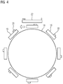
- the representation in FIG. 4 shows a situation with a plurality of carriages 16 coupled to a closed link chain.
- the carriages 16 are provided with an automatically interrogatable identifier.
- RFID tags and a corresponding reader both not shown
- any chain dimension errors can also be eliminated.
- only one of the carriages 16 is provided with an automatically interrogatable identifier.
Description
Die Erfindung betrifft ein Positionsmesssystem für verkettete Linearmotoren sowie ein Regelungsverfahren für solche Linearmotoren, das auf einer von dem Positionsmesssystem erhältlichen Positionsinformation basiert.The invention relates to a position measuring system for chained linear motors and a control method for such linear motors, which is based on a position information obtainable by the position measuring system.
Linearmotoren sind an sich bekannt. Auch verkettete Linearmotoren sind bekannt. Eine typische Beispielanwendung eines verketteten Linearmotors sind sogenannte Sorter, bei denen die einzelnen Motorglieder an zu einer Kette gekuppelten Carriern montiert sind. Typischerweise sind die Carrier in einer Endlosschleife geschlossen.Linear motors are known per se. Also linked linear motors are known. A typical example application of a linked linear motor are so-called sorters in which the individual motor links are mounted on carriers coupled to a chain. Typically, the carriers are closed in an infinite loop.
Unter einem verketteten Aufbau ist also insbesondere ein Linearmotor zu verstehen, bei dem entweder das Primärteil oder das Sekundärteil entlang der jeweiligen Fahrstrecke in einzelne Glieder unterteilt ist. Die Glieder sind zum Beispiel über eine Kupplung mechanisch miteinander verbunden. Aufgrund der Kupplung entstehen Lücken zwischen den Motorgliedern sowie Lücken in der magnetischen Polfolge. Bei Synchronmotoren entspricht die Weite einer solchen Lücke zweckmäßigerweise einem ganzzahligen Vielfachen n der Polteilung T = 360° elektrisch. Aufgrund der mechanischen Kupplung wird die Weite solcher Lücken jedoch niemals exakt der Polteilung entsprechen, sondern vielmehr Toleranzen aufweisen. Solche Toleranzen stören allerdings den Gleichlauf des Linearmotors.Under a concatenated structure is thus to be understood in particular a linear motor, in which either the primary part or the secondary part along the respective route is divided into individual members. The links are mechanically interconnected, for example, via a coupling. The coupling creates gaps between the motor links and gaps in the magnetic pole sequence. In synchronous motors, the width of such a gap expediently corresponds to an integer multiple n of the pole pitch T = 360 ° electrical. Due to the mechanical coupling, however, the width of such gaps will never correspond exactly to the pole pitch, but rather have tolerances. However, such tolerances disturb the synchronization of the linear motor.
Für eine wirkungsgradoptimale Regelung von Synchronmotoren mit gutem Gleichlauf sind gebergestützte Regelverfahren prinzipiell im Vorteil gegenüber geberlosen Verfahren, da sich bei geberlosen Regelungsverfahren die Lücken zwischen den Gliedern ungünstig auf die auf das Motormodell gestützte Berechnung der Pollage und der Geschwindigkeit auswirken.For optimum control of synchronous motors with good synchronization, encoder-based control methods have, in principle, the advantage over sensorless methods, since the gaps between the links have an unfavorable effect on the motor model-based calculation of the pole position and the speed in the case of sensorless control methods.
Problematisch ist in diesem Zusammenhang allerdings die ebenfalls gegliederte Realisierung des jeweiligen Gebers. Die oben erwähnten Toleranzen führen auch bei den Gebern zu Lücken schwankender Breite und damit bei vom Geber gelieferten Positionsinformationen zu Schwankungen über den Lücken. Dies erschwert die Auswertung und Verwendung der jeweiligen Messergebnisse für eine Regelung des Linearmotors bzw. führt wiederum zu schlechten Gleichlaufergebnissen und schlechtem Wirkungsgrad.The problem is in this context, however, the also structured implementation of the respective encoder. The tolerances mentioned above also lead to gaps in the encoders of varying widths and thus to position fluctuations that are supplied by the encoder over the gaps. This complicates the evaluation and use of the respective measurement results for a control of the linear motor or in turn leads to poor synchronization results and poor efficiency.
Als Geber zur Messung einer Pollage kommen zum Beispiel Magnetfeldsensoren in Betracht. Ein Beispiel für solche Magnetfeldsensoren ist ein sogenannter, an sich bekannter Hall-Sensor.For example, magnetic field sensors come into consideration as encoders for measuring a pole position. An example of such magnetic field sensors is a so-called Hall sensor known per se.
Beim Stand der Technik werden Maschinen, zum Beispiel Maschinen für die eingangs erwähnten Sorter-Anwendungen, mit herkömmlichen Linearsynchronmotoren realisiert. Bei der herkömmlichen Synchrontechnik für verkettete Linearmotoren werden im Fall einer Anwendung bei einem Sorter die beweglichen Motorglieder mit den Permanentmagneten des Motors bestückt. Zur Messung der Pollage der Sekundärteile sind als Magnetfeldsensoren Hall-Sensoren in Verlängerung des Primärteils angebracht. Der Nachteil einer solchen Lösung besteht allerdings darin, dass diese nur bei permanentmagnetischen Sekundärteilen anwendbar ist. Darüber hinaus werden die Hall-Sensoren ebenfalls durch Lücken zwischen den Motorgliedern gestört, so dass solche Störungen gegebenenfalls durch mehrere hintereinander angeordnete Hall-Sensoren ausgeglichen werden müssen. Letzteres führt zu einer Verlängerung des Primärteils. Bei Fahrstrecken mit vielen Kurven ist dies ein zusätzlicher Nachteil.In the prior art machines, for example, machines for the sorter applications mentioned above, realized with conventional linear synchronous motors. In the conventional synchronous technique for concatenated linear motors, in the case of application to a sorter, the movable motor members are fitted with the permanent magnets of the motor. To measure the pole position of the secondary parts, Hall sensors are mounted in the extension of the primary part as magnetic field sensors. The disadvantage of such a solution, however, is that it is only applicable to permanent magnetic secondary parts. In addition, the Hall sensors are also disturbed by gaps between the motor links, so that such interference may need to be compensated by several successively arranged Hall sensors. The latter leads to an extension of the primary part. For routes with many curves, this is an additional disadvantage.
Aus der
Eine Aufgabe der vorliegenden Erfindung besteht entsprechend darin, ein Positionsmesssystem anzugeben, das eine unterbrechungsfreie Messung über eine Lücke zwischen den Gliedern eines verketteten Linearmotors hinweg erlaubt. Eine weitere Aufgabe der Erfindung besteht darin, auf Basis einer mittels des Positionsmesssystems erhältlichen Positionsinformation ein Regelungsverfahren für verkettete Linearmotoren anzugeben.Accordingly, it is an object of the present invention to provide a position measuring system which allows uninterrupted measurement across a gap between the links of a chained linear motor. Another object of the invention is based on a means of position information to obtain a control method for chained linear motors.
Diese Aufgabe wird hinsichtlich des Positionsmesssystems erfindungsgemäß mit den Merkmalen des Anspruchs 1 gelöst. Dabei ist bei einem Positionsmesssystem für verkettete Linearmotoren Folgendes vorgesehen: Der Linearmotor umfasst zumindest ein Primärteil und zumindest zwei gekoppelte Sekundärteile oder zumindest ein Sekundärteil und zumindest zwei gekoppelte Primärteile. Die beweglichen Motorglieder, also die gekoppelten Primär- oder Sekundärteile, sind jeweils einem Wagen einer mit dem Linearmotor angetriebenen Wagenkette zugeordnet, wobei die Gesamtheit der Wagen beim Betrieb des Linearmotors entlang einer Fahrstrecke beweglich ist. Jedem Wagen ist ein Positionsgeber zugeordnet. Der Fahrstrecke ist ein für den Positionsgeber sensitiver Empfänger zugeordnet. Der Empfänger ist längs zur Fahrstrecke ausgerichtet und befindet sich zum Beispiel neben dem ortsfesten Motorteil, also bei beweglichen Motorgliedern in Form zumindest zweier verketteter Sekundärteile neben dem zumindest einen Primärteil oder bei beweglichen Motorgliedern in Form zumindest zweier verketteter Primärteile neben dem zumindest einen Sekundärteil. Mittels des Empfängers ist eine Positionsinformation generierbar oder ausgebbar, die eine relative Lage des Positionsgebers zum Empfänger kodiert. Dabei ist die Positionsinformation als eine numerische Wertzahl, welche durch die relative Lage des Positionsgebens (20) zum Empfänger (22) erzeugbar ist, ausgebildet. Der Empfänger weist eine im Vergleich zu einer in Fahrtrichtung der Wagen gemessenen Länge jedes Wagens zumindest gleich große Länge auf. Wenn der Empfänger eine im Vergleich zu einer in Fahrtrichtung der Wagen gemessenen Länge jedes Wagens größere Länge aufweist, ist gewährleistet, dass sich stets der Positionsgeber zumindest eines Wagens in einem Erfassungsbereich des Empfängers befindet. Damit ist stets eine zur geregelten Ansteuerung des verketteten Linearmotors geeignete Positionsinformation erhältlich, die nicht nur unabhängig von einer eventuell schwankenden Breite der Lücken zwischen den verketteten Primär- oder Sekundärteilen ist, sondern auch ein bisher oftmals beobachte tes Aufaddieren der aufgrund solcher Lücken resultierenden Fehler vermeidet. Des Weiteren ist vorgesehen, dass im Falle von zwei gleichzeitig im Erfassungsbereich des Empfängers befindlichen Positionsgebern zwei Positionsinformationen resultieren, von denen nur die numerisch kleinere Positionsinformation verwendet wird. Dies sorgt für mathematisch einfache Verhältnisse. Eine besondere Konstellation, bei der dies ausgenutzt wird, ist weiter unten beschrieben.This object is achieved with regard to the position measuring system according to the invention with the features of claim 1. The linear motor comprises at least one primary part and at least two coupled secondary parts or at least one secondary part and at least two coupled primary parts. The movable motor members, so the coupled primary or secondary parts, each associated with a carriage of a driven with the linear motor carriage chain, the entirety of the carriage during operation of the linear motor along a driving distance is movable. Each car is assigned a position transmitter. The route is assigned a sensitive for the position sensor receiver. The receiver is aligned longitudinally to the route and is located, for example, next to the stationary motor part, ie movable motor links in the form of at least two chained secondary parts next to the at least one primary part or moving motor links in the form of at least two chained primary parts next to the at least one secondary part. By means of the receiver, a position information can be generated or output, which encodes a relative position of the position sensor to the receiver. In this case, the position information is formed as a numerical value number, which can be generated by the relative position of the position input (20) to the receiver (22). The receiver has a length of each carriage, measured in the direction of travel of the car, of at least equal length. If the receiver has a greater length compared to a length of each carriage measured in the direction of travel of the car, it is ensured that the position transmitter of at least one carriage is always located in a detection range of the receiver. Thus, a suitable for controlled control of the concatenated linear motor position information is always available, which is not only independent of any fluctuating width of the gaps between the chained primary or secondary parts, but also a hitherto often observed Adding up the resulting errors due to such gaps avoids. Furthermore, it is provided that in the case of two position sensors located simultaneously in the detection range of the receiver, two position information results, of which only the numerically smaller position information is used. This ensures mathematically simple conditions. A particular constellation in which this is exploited is described below.
Wenn der Empfänger nur eine gleich große Länge wie die Wagen aufweist (oder gegebenenfalls auch kürzer ist), besteht die Möglichkeit, dass zu bestimmten Zeitpunkten, wenn also kein Positionsgeber im Erfassungsbereich des Empfängers ist, keine Positionsinformation vom Empfänger erhältlich ist. Dann schaltet das Positionsmesssystem automatisch in einen geberlosen, insbesondere motormodellgestützten Betrieb um verwendet die so erhältliche Positionsinformation solange, bis wieder ein Positionsgeber in den Erfassungsbereich des Empfängers eintritt und das Positionsmesssystem dann wieder automatisch auf die Erfassung der Positionsinformation mittels des Empfängers umschaltet. Dies ist auch eine Möglichkeit, wie das Positionsmesssystem automatisch mit einer Fehlersituation in Form eines fehlenden oder in seiner Position verstellten Positionsgebers umgehen kann. Dann kommt nämlich in Betracht auf Basis der fehlenden Erfassung eines Positionsgebers nicht unmittelbar ein Fehlersignal zu erzeugen, sondern automatisch ebenfalls auf einen geberlosen, insbesondere motormodellgestützten Betrieb umzuschalten. Die Auslösung eines Fehlersignals kann dann zum Beispiel dennoch erfolgen, wenn innerhalb einer vorgegebenen oder vorgebbaren Zeitspanne kein gültiges Signal von der Positionsgeber-Empfänger-Kombination erhältlich ist. Zur Überwachung kommt zum Beispiel ein sogenannter Watchdog in Betracht.If the receiver has only the same length as the carriages (or shorter if necessary), there is the possibility that at certain times, when there is no position sensor in the detection range of the receiver, no position information from the receiver is available. The position measuring system then automatically switches to an encoderless, in particular motor model-based, operation using the position information available in this way until a position sensor again enters the detection range of the receiver and the position measuring system then automatically switches back to the detection of the position information by means of the receiver. This is also a possibility of how the position measuring system can automatically deal with an error situation in the form of a position transmitter that is missing or displaced in its position. Then comes into consideration on the basis of the lack of detection of a position sensor does not directly generate an error signal, but automatically switch to an encoderless, in particular motor model-based operation. The triggering of an error signal can then take place, for example, if within a given or predefinable time period no valid signal from the position transmitter-receiver combination is available. For monitoring, for example, a so-called watchdog comes into consideration.
Vorteilhafte Ausgestaltungen der Erfindung sind Gegenstand der Unteransprüche. Dabei verwendete Rückbeziehungen weisen auf die weitere Ausbildung des Gegenstandes des Hauptanspruches durch die Merkmale des jeweiligen Unteranspruches hin. Sie sind nicht als ein Verzicht auf die Erzielung eines selbständigen, gegenständlichen Schutzes für die Merkmalskombinationen der rückbezogenen Unteransprüche zu verstehen. Des Weiteren ist im Hinblick auf eine Auslegung der Ansprüche bei einer näheren Konkretisierung eines Merkmals in einem nachgeordneten Anspruch davon auszugehen, dass eine derartige Beschränkung in den jeweils vorangehenden Ansprüchen nicht vorhanden ist. Schließlich ist darauf hinzuweisen, dass das hier angegebene Verfahren auch entsprechend der abhängigen Vorrichtungsansprüche weitergebildet sein kann und umgekehrt.Advantageous embodiments of the invention are the subject of the dependent claims. Here used backlinks indicate the further development of the subject matter of the main claim by the features of the respective subclaim. They should not be construed as a waiver of obtaining independent, objective protection for the feature combinations of the dependent claims. Furthermore, with a view to an interpretation of the claims in a closer specification of a feature in a subordinate claim, it can be assumed that such a restriction is not present in the respective preceding claims. Finally, it should be noted that the method specified here can also be developed according to the dependent device claims and vice versa.
Bei einer besonderen Ausführungsform des Positionsmesssystems wird gewährleistet, dass bei mehr als einer Positionsinformation stets nur die numerisch kleinste Positionsinformation verwendet wird, indem das Positionsmesssystem nur die numerisch kleinste Positionsinformation an eine Steuerungs-/Regelungseinrichtung des verketteten Linearmotors übermittelt. Letzteres minimiert die Anforderungen an eine Schnittstelle zwischen dem Positionsmesssystem und der Steuerungs-/Regelungseinrichtung.In a particular embodiment of the position measuring system ensures that in more than one position information always only the numerically smallest position information is used by the position measuring system transmits only the numerically smallest position information to a control / regulating device of the concatenated linear motor. The latter minimizes the requirements for an interface between the position measuring system and the control / regulating device.
Als Empfänger und Positionsgeber kommen ein magnetostriktiver Wegaufnehmer bzw. ein Permanentmagnet in Betracht. Ein solcher Empfänger/Wegaufnehmer hat den Vorteil, dass dessen Generierung einer Positionsinformation anhand einer Lage des Permanentmagneten relativ zu seiner Längserstreckung nicht durch die von dem verketteten Linearmotor ausgehenden Magnetfelder beeinflusst wird. Alternativ kommt grundsätzlich auch eine Empfänger-Positionsgeber-Kombination in Betracht, die auf einem kapazitiven, optischen, magnetischen, resistiven, usw. Wirkprinzip beruht.As a receiver and position sensor are a magnetostrictive transducer or a permanent magnet into consideration. Such a receiver / displacement transducer has the advantage that its generation of position information based on a position of the permanent magnet relative to its longitudinal extent is not influenced by the magnetic fields emanating from the linked linear motor. Alternatively, in principle, a receiver-position encoder combination comes into consideration, which is based on a capacitive, optical, magnetic, resistive, etc. operating principle.
Bei einer weiteren Ausführungsform des Positionsmesssystems sind die Positionsgeber jeweils in der Mitte des einem Wagen zugeordneten Primär- oder Sekundärteils angeordnet. Dies gewährleistet eine ausreichende Überdeckung der jeweiligen beweglichen und ortsfesten Motorglieder, sobald und solange sich der Positionsgeber im Erfassungsbereich des Empfängers befindet.In a further embodiment of the position measuring system, the position sensors are each arranged in the middle of a primary or secondary part associated with a car. This ensures adequate coverage of the respective moving and stationary motor links as and as long as the locator is within the detection range of the receiver.
Die oben genannte Aufgabe wird auch mit einem Regelungsverfahren für einen verketteten Linearmotor gelöst, das sich dadurch auszeichnet, dass ein Istwert für eine Regelung des verketteten Linearmotors mittels eines Positionsmesssystems der hier und im Folgenden beschrieben Art ermittelt wird. Der Vorteil der Verwendung eines solchen und im Folgenden mit weiteren Details beschriebenen Positionsmesssystems besteht darin, dass die von dem Positionsmesssystem erhältliche Positionsinformation die Verwendung bekannter Regelungsverfahren und -algorithmen erlaubt.The abovementioned object is also achieved with a control method for a linked linear motor, which is characterized in that an actual value for a control of the linked linear motor is determined by means of a position measuring system of the type described here and below. The advantage of using such a position measuring system described below in further detail is that the position information obtainable from the position measuring system allows the use of known control methods and algorithms.
Vorteilhafte Ausgestaltungen des Regelungsverfahrens sind Gegenstand der auf den betreffenden Anspruch rückbezogenen Unteransprüche oder ergeben sich aus einer Umsetzung einzelner oder mehrerer Merkmale des Anspruchs und der darauf rückbezogenen Ansprüche.Advantageous embodiments of the regulatory procedure are the subject of the dependent claims referring back to the claim in question or result from an implementation of one or more features of the claim and the claims based thereon.
Bei einer Ausführungsform des Regelungsverfahrens werden die von dem Positionsmesssystem erhaltenen Positionsinformationen auf einen Winkelbereich von 0° bis 359° abgebildet und die Motorregelung erfolgt wie die Regelung bei einem rotierenden Synchronmotor. Dies ist ein Beispiel für die weiter oben erwähnten einfachen Verhältnisse, die mit dem hier vorgeschlagenen Verfahren ausgenutzt werden können. Die Grundlagen für eine Regelung eines rotierenden Synchronmotors sind seit langem bekannt. Auf diese kann bei der Abbildung der zunächst eine lineare Position kodierenden Positionsinformationen auf den Winkelbereich eines Vollkreises zurückgegriffen werden.In one embodiment of the control method, the position information obtained from the position measuring system is mapped to an angle range of 0 ° to 359 ° and the motor control is like the control in a rotating synchronous motor. This is an example of the above-mentioned simple relationships that can be exploited with the method proposed here. The basics for a control of a rotating synchronous motor have long been known. This can be used in the mapping of the first linear position encoding position information on the angle range of a full circle.
Bei einer weiteren Ausführungsform des Regelungsverfahrens wird zum Erhalt einer Information zur absoluten Position des Linearmotors eine Positionsinformation in einem Bereich von 0° bis zu einem der Anzahl der Wagen entsprechenden Vielfachen von 360° erfasst.In another embodiment of the control method, to obtain information about the absolute position of the linear motor, position information in a range of 0 ° to a multiple of 360 ° corresponding to the number of carriages is detected.
Wenn gemäß einer nochmals weiteren Ausführungsform des Regelungsverfahrens zumindest einer der Wagen mit einer automatisch abfragbaren Kennung, insbesondere einem RFID-Tag, versehen ist, lässt sich bei einer geschlossenen Kette der beweglichen Motorglieder nach einem Durchlauf eine Absolutposition ermitteln.If, according to yet another embodiment of the control method, at least one of the carriages is provided with an automatically interrogatable identifier, in particular an RFID tag, it is possible to determine an absolute position after a passage in a closed chain of the movable motor members.
Wenn bei einer besonderen Ausführungsform alle Wagen mit einer automatisch abfragbaren Kennung versehen sind, braucht ein solcher vollständiger Durchlauf nicht abgewartet werden.In a particular embodiment, if all cars are provided with an automatically interrogatable identifier, such a full pass need not be awaited.
Nachfolgend wird ein Ausführungsbeispiel der Erfindung anhand der Zeichnung näher erläutert. Einander entsprechende Gegenstände oder Elemente sind in allen Figuren mit den gleichen Bezugszeichen versehen.An embodiment of the invention will be explained in more detail with reference to the drawing. Corresponding objects or elements are provided in all figures with the same reference numerals.
Das Ausführungsbeispiel ist nicht als Einschränkung der Erfindung zu verstehen. Vielmehr sind im Rahmen der vorliegenden Offenbarung auch Modifikationen möglich, insbesondere solche Varianten und Kombinationen, die zum Beispiel durch Kombination oder Abwandlung von einzelnen in Verbindung mit den im allgemeinen oder speziellen Beschreibungsteil beschriebenen sowie in den Ansprüchen und/oder der Zeichnung enthaltenen Merkmalen bzw. Elementen oder Verfahrensschritten für den Fachmann im Hinblick auf die Lösung der Aufgabe entnehmbar sind und durch kombinierbare Merkmale zu einem neuen Gegenstand oder zu neuen Verfahrensschritten bzw. Verfahrensschrittfolgen führen.The embodiment is not to be understood as limiting the invention. Rather, in the context of the present disclosure, modifications are possible, in particular those variants and combinations, for example, by combination or modification of individual in combination with the described in the general or specific description part and in the claims and / or the drawings features or elements or process steps for the expert in terms of solving the problem can be removed and lead by combinable features to a new subject or to new process steps or process steps.
Es zeigen:
- FIG 1
- eine schematisch vereinfachte Darstellung eines Line-armotors mit einem einer Fahrstrecke zugeordneten Primärteil und einem beweglichen Sekundärteil,
- FIG 2
- eine schematisch vereinfachte Darstellung eines verketteten Linearmotors mit einem Primärteil und mehreren gekoppelten Sekundärteilen sowie eine Momentaufnahme bei der Bewegung der Sekundärteile,
- FIG 3
- eine Momentaufnahme wie in
FIG 2 , allerdings zu einem anderen Zeitpunkt und - FIG 4
- eine Situation, bei der die beweglichen Motorglieder eines verketteten Linearmotors in einer geschlossenen Kette angeordnet sind, und die damit entlang einer ebenfalls geschlossenen Fahrstrecke beweglichen Wagen einer mit einem solchen Motor realisierten Maschine.
- FIG. 1
- a schematically simplified representation of a line-armotors with a driving distance associated primary part and a movable secondary part,
- FIG. 2
- a schematically simplified representation of a concatenated linear motor with a primary part and several coupled secondary parts as well as a snapshot during the movement of the secondary parts,
- FIG. 3
- a snapshot like in
FIG. 2 but at another time and - FIG. 4
- a situation in which the moving motor links of a chained linear motor are arranged in a closed chain, and thus along a likewise closed driving path movable carriage of a realized with such a motor machine.
Die Darstellung in
Das Primärteil 12 umfasst in an sich bekannter Art und Weise Permanentmagnete (nicht gezeigt) und ist in die jeweilige Fahrstrecke (Fahrweg) 18 integriert. Das oder jedes Sekundärteil 14 weist in ebenfalls an sich bekannter Art und Weise einen in Bewegungsrichtung orientierten, gezahnten Eisenkern (nicht gezeigt) auf. Die Bewegungsrichtung ist in
Die Erwähnung des Primärteils 12 als ortsfest ist nur beispielhaft zu verstehen. Tatsächlich ist es nicht relevant, ob verkettete Primärteile 12 oder verkettete Sekundärteile 14 als bewegliche Motorglieder und damit als Basis für die Wagen 16 fungieren. Die Beschreibung des Ausführungsbeispiels wird - ohne Verzicht auf eine weitergehende Allgemeingültigkeit - anhand eines ortsfesten Primärteils 12 und mehrerer beweglicher und verketteter Sekundärteile 14 fortgesetzt.The mention of the
In
Bei dem Empfänger 22 handelt es zum Beispiel um einen grundsätzlich an sich bekannten, magnetostriktiven Wegaufnehmer. Ein mit einem solchen Empfänger 22 zusammenwirkender Positionsgeber 20 ist ein an jedem Wagen 16 insbesondere mittig zum dortigen Sekundärteil 14 angebrachter Permanentmagnet. Eine Beschreibung der Funktion eines magnetostriktiven Wegaufnehmers scheint hier nicht erforderlich. Stattdessen wird auf die insoweit einschlägige Literatur verwiesen. Als Empfänger 22 in Form eines magnetostriktiven Wegaufnehmers kommt zum Beispiel ein von dem Unternehmen MTS Systems Corporation unter der Marke "Temposonics" angebotener Sensor in Betracht. Der Vorteil der Verwendung eines magnetostriktiven Wegaufnehmers als Empfänger 22 besteht vor allem darin, dass dessen Positionsauswertung offenbar unabhängig von den vom Linearmotor 10 ausgehenden Magnetfeldern ist, zumindest hat sich herausgestellt, dass vom Linearmotor 10 ausgehende Streufelder aufgrund des Abstands unkritisch sind. Weitere Vorteile sind ein einfacher Sender (Positionsgeber 20), nämlich ein Sender in Form eines Permanentmagneten, die Unempfindlichkeit der Positionsgeber-Empfänger-Kombination, gegen Einflüsse, wie sie im industriellen Einsatz oftmals zu erwarten sind, also zum Beispiel eine Unempfindlichkeit gegen Staub, Öl und dergleichen, sowie eine größere Toleranz als zum Beispiel optische Geber im Hinblick auf den Abstand (Luftspalt) zwischen Positionsgeber und Empfänger.The
Die Darstellung in
Wenn sich ein Positionsgeber 20 im Erfassungsbereich des Empfängers 22 befindet, erzeugt der Empfänger 22 eine Positionsinformation entsprechend dem Ort des Positionsgebers 20 relativ zum Empfänger 22. Symbolisch kann die dabei erzeugte Positionsinformation ("pos") als insbesondere natürliche Zahl in einem Intervall von "0" bis zu einem Maximalwert "max" ( pos = [0..max] ) angegeben werden. Diese Werte sind auch in der Darstellung in
Die Darstellung in
Aufgrund der regelmäßigen Abfolge der Positionsgeber 20 innerhalb der durch die gekoppelten Wagen 16 gebildeten Kette wird hier vorgeschlagen, für eine Regelung des verketteten Linearmotors 10 die von dem Empfänger 22 jeweils gelieferte Positionsinformation ("pos1") wie eine absolute Winkelposition bei einer Regelung eines rotierenden Synchronmotors zu interpretieren. Bei einer Bewegung der Wagen 16 (
Die Verwendung einer Regelung, wie sie von einem rotierenden Synchronmotor bekannt ist, wird dann besonders einfach, wenn dem Minimalwert die Winkellage 0° und dem jeweils tatsächlich erreichten Maximalwert die Winkellage 359° zugeordnet wird. Dann entspricht ein Fahrweg zwischen zwei Positionsgebern 20 einer virtuellen Geberumdrehung.The use of a control, as it is known from a rotating synchronous motor, is then particularly simple if the angular position is assigned to the
Bei insgesamt k Wagen 16 innerhalb der Kette haben alle Wagen 16 nach k x 360° den Empfänger 22 passiert, d.h. nach k x 360° ist die gesamte Kette einmal abgefahren. Damit ist auch die Absolutposition der ganzen Kette in jeder Stellung bekannt.For a total of
Innerhalb einer virtuellen Geberumdrehung von 0° bis 359°, die zweckmäßigerweise einem ganzzahligen Vielfachen der Polteilung der Sekundärteile 14 entspricht, kann die bei permanentmagneterregten Synchronmotoren übliche Motorregelung verwendet werden. Bei den Übergängen zwischen 0° und 359° wird die bei einem Synchronmotor mit Singleturnabsolutwertgeber übliche Zählmethode eingesetzt.Within a virtual encoder revolution of 0 ° to 359 °, which expediently corresponds to an integer multiple of the pole pitch of the
Die Darstellung in
Als ideale Position des Positionsgebers 20 relativ zum Sekundärteil 14 (
Obwohl die Erfindung im Detail durch das Ausführungsbeispiel näher illustriert und beschrieben wurde, so ist die Erfindung nicht durch das oder die offenbarten Beispiele eingeschränkt und andere Variationen können vom Fachmann hieraus abgeleitet werden, ohne den Schutzumfang der Erfindung zu verlassen.While the invention has been further illustrated and described in detail by the exemplary embodiment, the invention is not limited by the disclosed or disclosed examples, and other variations can be derived therefrom by those skilled in the art without departing from the scope of the invention.
Einzelne im Vordergrund stehende Aspekte der hier eingereichten Beschreibung lassen sich damit kurz wie folgt zusammenfassen:
- Die Erfindung ist ein Positionsmesssystem für verkettete Linearmotoren 10, mit einem längs zur jeweiligen Fahrstrecke 18 ausgerichteten Empfänger 22 und einem Positionsgeber 20 an jedem beweglichen Motorglied, wobei mittels des Empfängers 22 eine Positionsinformation generierbar oder ausgebbar ist, die eine relative Lage des
Positionsgebers 20zum Empfänger 22 kodiert, und wobei der Empfänger 22 eine im Vergleich zu einer inFahrtrichtung der Wagen 16 gemessenen Länge jedes Wagens 16 größere Länge aufweist. Die beschriebene Positionsmesseinrichtung stellt sicher, dass sich Lücken zwischen mehreren Gliedern eines verketteten Linearmotors 10 über mehrere Glieder (Wagen 16) hinweg nicht zu einem bei der Motorregelung merklichen Kettenfehler aufaddieren können. Eine gegebenenfalls notwendige Lücke zwischenden Sekundärteilen 14 wird man vorzugsweise möglichst genau entsprechend einer Polteilung T = 360° elektrisch realisieren, wobei typische Polteilungen ausgeführter Motoren durchaus Versätze im Bereich von +/- 1 mm zulassen, ohne die Kraftwirkung des Primärteils 12 im Übergangsbereich zwischen zwei Sekundärteilen 14 zu beeinträchtigen. Größere, möglichst ganzzahlige Vielfache von T sind möglich, reduzieren aber die Motorkraftwirkung.
- The invention is a position measuring system for chained
linear motors 10, with a longitudinally to therespective route 18 alignedreceiver 22 and aposition sensor 20 on each movable motor member, wherein by means of thereceiver 22 position information can be generated or output, the relative position of theposition sensor 20 to thereceiver 22, and wherein thereceiver 22 is one compared to a In the direction of travel of thecarriage 16 measured length of eachcarriage 16 has greater length. The described position measuring device ensures that gaps between several links of a linkedlinear motor 10 over several links (carriage 16) can not add up to a chain error that is noticeable during motor control. An optionally necessary gap between thesecondary parts 14 will preferably be realized as accurately as possible according to a pole pitch T = 360 °, with typical pole pitches of executed motors quite allow offsets in the range of +/- 1 mm, without the force of theprimary part 12 in the transition region between two Affectingsecondary parts 14. Larger, possibly integer multiples of T are possible, but reduce the engine power effect.
Claims (7)
- Position measuring system for concatenated linear motors (10),- wherein the linear motor (10) comprises at least one primary part (12) and at least two coupled secondary parts (14) or at least one secondary part (14) and at least two coupled primary parts (12),- wherein the coupled primary or secondary parts (12, 14) in each case are associated with one carriage (16) of a chain of carriages and wherein the entirety of the coupled carriages (16) can move along a track (18) during operation of the linear motor (10),- wherein each carriage (16) is associated with a position sensor (20),- wherein the track (18) is associated with a receiver (22) which is sensitive to the position sensor (20),- wherein the receiver (22) is aligned longitudinally to the track (18),- wherein by means of the receiver (22), position information can be generated or output which encodes a position of the position sensor (20) relative to the receiver (22), and wherein the position information is embodied as a numerical value which can be generated by the position of the position sensor (20) relative to the receiver (22), and- wherein the receiver (22) has a length at least equal in comparison to a length of each carriage (16) measured in the direction of travel of the carriage (16),characterised in that- in the case of two position sensors (20) simultaneously located in a detection area of the receiver (22), namely a first position sensor (20) of a first carriage (16) and a second position sensor (20) of a second carriage (16) coupled to the first carriage (16), the result is two sets of position information and only the numerically smaller set of position information is used and- that the position information received from the position measuring system is mapped to an angular range of between 0° and 359°.
- Position measuring system according to claim 1, wherein the receiver (22) is a magnetostrictive position transducer and the position sensor (20) is a permanent magnet.
- Position measuring system according to one of claims 1 or 2, wherein the position sensor (20) is arranged in the middle of the primary or secondary part (12, 14) associated with a carriage (16).
- Control method for a concatenated linear motor (10), wherein an actual value for control of the concatenated linear motor (10) by means of a position measuring system according to one of claims 1 to 3 is determined and the motor control is effected in the same way as control for a rotary synchronous motor.
- Control method according to claim 4, wherein for obtaining information on the absolute position of the linear motor (10), position information is captured in a range from 0° up to a multiple of 360° corresponding to the number of carriages (16).
- Control method according to one of claims 4 or 5, wherein at least one of the carriages (16) is provided with an automatically interrogatable identifier, in particular an RFID tag.
- Control method according to claim 6, wherein all carriages (16) are provided with an automatically interrogatable identifier.
Priority Applications (1)
| Application Number | Priority Date | Filing Date | Title |
|---|---|---|---|
| EP13190680.2A EP2869035B1 (en) | 2013-10-29 | 2013-10-29 | Position measuring system and control method for linear motors linked together |
Applications Claiming Priority (1)
| Application Number | Priority Date | Filing Date | Title |
|---|---|---|---|
| EP13190680.2A EP2869035B1 (en) | 2013-10-29 | 2013-10-29 | Position measuring system and control method for linear motors linked together |
Publications (2)
| Publication Number | Publication Date |
|---|---|
| EP2869035A1 EP2869035A1 (en) | 2015-05-06 |
| EP2869035B1 true EP2869035B1 (en) | 2016-08-03 |
Family
ID=49552169
Family Applications (1)
| Application Number | Title | Priority Date | Filing Date |
|---|---|---|---|
| EP13190680.2A Active EP2869035B1 (en) | 2013-10-29 | 2013-10-29 | Position measuring system and control method for linear motors linked together |
Country Status (1)
| Country | Link |
|---|---|
| EP (1) | EP2869035B1 (en) |
Cited By (1)
| Publication number | Priority date | Publication date | Assignee | Title |
|---|---|---|---|---|
| CN108574378A (en) * | 2017-03-13 | 2018-09-25 | B和R工业自动化有限公司 | The method of the absolute position of mover for determining linear motor |
Families Citing this family (2)
| Publication number | Priority date | Publication date | Assignee | Title |
|---|---|---|---|---|
| CN113714113A (en) * | 2021-01-11 | 2021-11-30 | 北京京东乾石科技有限公司 | Monitoring device and system of secondary plate and cross belt sorting machine |
| CN114142669A (en) * | 2021-12-03 | 2022-03-04 | 航天科技控股集团股份有限公司 | Linear motor adjusting structure for track system |
Family Cites Families (5)
| Publication number | Priority date | Publication date | Assignee | Title |
|---|---|---|---|---|
| WO2004103792A1 (en) * | 2003-05-21 | 2004-12-02 | Schierholz-Translift Schweiz Ag | Rail assembly, rail switch and a transport device provided with a magnetostrictive sensor |
| DE102008008602B4 (en) * | 2007-06-22 | 2018-03-29 | Siemens Aktiengesellschaft | Transfer device for workpiece carriers and method for transporting workpiece carriers |
| DE502008002888D1 (en) * | 2008-09-09 | 2011-04-28 | Siemens Ag | Transfer device with dynamically variable drive ranges |
| DE102009041483A1 (en) * | 2009-09-14 | 2011-03-31 | Siemens Aktiengesellschaft | Measuring system for position determination of primary part of linear motor relative to secondary part, has absolute value measurement system for detecting reference position of primary part relative to secondary part |
| DE202009015916U1 (en) * | 2009-11-23 | 2010-03-11 | Noell Mobile Systems Gmbh | Sensor system for conveyor systems with linear synchronous motor drive and conveyor system |
-
2013
- 2013-10-29 EP EP13190680.2A patent/EP2869035B1/en active Active
Cited By (2)
| Publication number | Priority date | Publication date | Assignee | Title |
|---|---|---|---|---|
| CN108574378A (en) * | 2017-03-13 | 2018-09-25 | B和R工业自动化有限公司 | The method of the absolute position of mover for determining linear motor |
| CN108574378B (en) * | 2017-03-13 | 2021-08-31 | B和R工业自动化有限公司 | Method for determining an absolute position of a mover of a linear motor |
Also Published As
| Publication number | Publication date |
|---|---|
| EP2869035A1 (en) | 2015-05-06 |
Similar Documents
| Publication | Publication Date | Title |
|---|---|---|
| EP3376166B1 (en) | Method for determining the absolution position of a runner of a linear motor | |
| EP2673224B1 (en) | Transport device with identification function | |
| DE102009041483A1 (en) | Measuring system for position determination of primary part of linear motor relative to secondary part, has absolute value measurement system for detecting reference position of primary part relative to secondary part | |
| EP2115396B1 (en) | Method and system for determining the position of a motor part | |
| EP2860496B1 (en) | Linear motor | |
| DE102006016503A1 (en) | Encoder device for an electrical machine | |
| EP2568582B1 (en) | Electric machine | |
| DE102010028333A1 (en) | Incremental multi-position detection system for a circulating electromagnetic transfer system | |
| WO2014086525A1 (en) | Sensor apparatus for determining at least one rotation property of a rotating element | |
| DE102005045374A1 (en) | Measuring device with a measuring head for determining the position of a primary part on a secondary part and method for determining the position of a primary part on a secondary part with a measuring head | |
| EP2568261A2 (en) | Positioning / distance measuring system | |
| DE4301971A1 (en) | ||
| DE102008046741A1 (en) | Inductive position sensor, measuring system equipped therewith and method for operating a position sensor | |
| EP2869035B1 (en) | Position measuring system and control method for linear motors linked together | |
| WO2008019988A1 (en) | Electric motor with measuring system for positions or movements | |
| EP3803278B1 (en) | Absolute encoder | |
| WO2004013576A1 (en) | Device for positional and/or length determination | |
| EP2869031B1 (en) | Position measuring device | |
| EP2159549B1 (en) | Device for measuring the relative position between a material measure and a read head | |
| DE102005017498A1 (en) | Synchronous linear motor with contactless scanning of the tooth structure of the abutment | |
| EP2116814B1 (en) | Measuring device for calculating a position and/or a speed | |
| EP2469239B1 (en) | Multi-turn angle measuring device | |
| DE102017205267A1 (en) | Position measuring device and method for operating a position measuring device | |
| DE10135540A1 (en) | Measurement device for determining position and velocity of the moving part of a linear electric motor relative to a stationary part, for use in motor control, by measuring the varying field strength of fixed magnets | |
| WO2013026434A1 (en) | Incremental travel sensor |
Legal Events
| Date | Code | Title | Description |
|---|---|---|---|
| PUAI | Public reference made under article 153(3) epc to a published international application that has entered the european phase |
Free format text: ORIGINAL CODE: 0009012 |
|
| 17P | Request for examination filed |
Effective date: 20140704 |
|
| AK | Designated contracting states |
Kind code of ref document: A1 Designated state(s): AL AT BE BG CH CY CZ DE DK EE ES FI FR GB GR HR HU IE IS IT LI LT LU LV MC MK MT NL NO PL PT RO RS SE SI SK SM TR |
|
| AX | Request for extension of the european patent |
Extension state: BA ME |
|
| 17Q | First examination report despatched |
Effective date: 20150626 |
|
| GRAP | Despatch of communication of intention to grant a patent |
Free format text: ORIGINAL CODE: EPIDOSNIGR1 |
|
| RIC1 | Information provided on ipc code assigned before grant |
Ipc: H02K 41/03 20060101ALI20160122BHEP Ipc: H02K 11/215 20160101ALI20160122BHEP Ipc: G01D 5/48 20060101AFI20160122BHEP |
|
| INTG | Intention to grant announced |
Effective date: 20160222 |
|
| GRAS | Grant fee paid |
Free format text: ORIGINAL CODE: EPIDOSNIGR3 |
|
| GRAA | (expected) grant |
Free format text: ORIGINAL CODE: 0009210 |
|
| AK | Designated contracting states |
Kind code of ref document: B1 Designated state(s): AL AT BE BG CH CY CZ DE DK EE ES FI FR GB GR HR HU IE IS IT LI LT LU LV MC MK MT NL NO PL PT RO RS SE SI SK SM TR |
|
| REG | Reference to a national code |
Ref country code: GB Ref legal event code: FG4D Free format text: NOT ENGLISH |
|
| REG | Reference to a national code |
Ref country code: CH Ref legal event code: EP Ref country code: AT Ref legal event code: REF Ref document number: 817632 Country of ref document: AT Kind code of ref document: T Effective date: 20160815 |
|
| REG | Reference to a national code |
Ref country code: IE Ref legal event code: FG4D Free format text: LANGUAGE OF EP DOCUMENT: GERMAN |
|
| REG | Reference to a national code |
Ref country code: DE Ref legal event code: R096 Ref document number: 502013003925 Country of ref document: DE |
|
| REG | Reference to a national code |
Ref country code: FR Ref legal event code: PLFP Year of fee payment: 4 |
|
| REG | Reference to a national code |
Ref country code: NL Ref legal event code: MP Effective date: 20160803 |
|
| REG | Reference to a national code |
Ref country code: LT Ref legal event code: MG4D |
|
| PG25 | Lapsed in a contracting state [announced via postgrant information from national office to epo] |
Ref country code: IS Free format text: LAPSE BECAUSE OF FAILURE TO SUBMIT A TRANSLATION OF THE DESCRIPTION OR TO PAY THE FEE WITHIN THE PRESCRIBED TIME-LIMIT Effective date: 20161203 Ref country code: HR Free format text: LAPSE BECAUSE OF FAILURE TO SUBMIT A TRANSLATION OF THE DESCRIPTION OR TO PAY THE FEE WITHIN THE PRESCRIBED TIME-LIMIT Effective date: 20160803 Ref country code: NO Free format text: LAPSE BECAUSE OF FAILURE TO SUBMIT A TRANSLATION OF THE DESCRIPTION OR TO PAY THE FEE WITHIN THE PRESCRIBED TIME-LIMIT Effective date: 20161103 Ref country code: NL Free format text: LAPSE BECAUSE OF FAILURE TO SUBMIT A TRANSLATION OF THE DESCRIPTION OR TO PAY THE FEE WITHIN THE PRESCRIBED TIME-LIMIT Effective date: 20160803 Ref country code: FI Free format text: LAPSE BECAUSE OF FAILURE TO SUBMIT A TRANSLATION OF THE DESCRIPTION OR TO PAY THE FEE WITHIN THE PRESCRIBED TIME-LIMIT Effective date: 20160803 Ref country code: LT Free format text: LAPSE BECAUSE OF FAILURE TO SUBMIT A TRANSLATION OF THE DESCRIPTION OR TO PAY THE FEE WITHIN THE PRESCRIBED TIME-LIMIT Effective date: 20160803 Ref country code: RS Free format text: LAPSE BECAUSE OF FAILURE TO SUBMIT A TRANSLATION OF THE DESCRIPTION OR TO PAY THE FEE WITHIN THE PRESCRIBED TIME-LIMIT Effective date: 20160803 |
|
| PG25 | Lapsed in a contracting state [announced via postgrant information from national office to epo] |
Ref country code: PT Free format text: LAPSE BECAUSE OF FAILURE TO SUBMIT A TRANSLATION OF THE DESCRIPTION OR TO PAY THE FEE WITHIN THE PRESCRIBED TIME-LIMIT Effective date: 20161205 Ref country code: SE Free format text: LAPSE BECAUSE OF FAILURE TO SUBMIT A TRANSLATION OF THE DESCRIPTION OR TO PAY THE FEE WITHIN THE PRESCRIBED TIME-LIMIT Effective date: 20160803 Ref country code: LV Free format text: LAPSE BECAUSE OF FAILURE TO SUBMIT A TRANSLATION OF THE DESCRIPTION OR TO PAY THE FEE WITHIN THE PRESCRIBED TIME-LIMIT Effective date: 20160803 Ref country code: GR Free format text: LAPSE BECAUSE OF FAILURE TO SUBMIT A TRANSLATION OF THE DESCRIPTION OR TO PAY THE FEE WITHIN THE PRESCRIBED TIME-LIMIT Effective date: 20161104 Ref country code: ES Free format text: LAPSE BECAUSE OF FAILURE TO SUBMIT A TRANSLATION OF THE DESCRIPTION OR TO PAY THE FEE WITHIN THE PRESCRIBED TIME-LIMIT Effective date: 20160803 Ref country code: BE Free format text: LAPSE BECAUSE OF NON-PAYMENT OF DUE FEES Effective date: 20161031 Ref country code: PL Free format text: LAPSE BECAUSE OF FAILURE TO SUBMIT A TRANSLATION OF THE DESCRIPTION OR TO PAY THE FEE WITHIN THE PRESCRIBED TIME-LIMIT Effective date: 20160803 |
|
| PG25 | Lapsed in a contracting state [announced via postgrant information from national office to epo] |
Ref country code: EE Free format text: LAPSE BECAUSE OF FAILURE TO SUBMIT A TRANSLATION OF THE DESCRIPTION OR TO PAY THE FEE WITHIN THE PRESCRIBED TIME-LIMIT Effective date: 20160803 Ref country code: RO Free format text: LAPSE BECAUSE OF FAILURE TO SUBMIT A TRANSLATION OF THE DESCRIPTION OR TO PAY THE FEE WITHIN THE PRESCRIBED TIME-LIMIT Effective date: 20160803 |
|
| REG | Reference to a national code |
Ref country code: DE Ref legal event code: R097 Ref document number: 502013003925 Country of ref document: DE |
|
| PG25 | Lapsed in a contracting state [announced via postgrant information from national office to epo] |
Ref country code: SK Free format text: LAPSE BECAUSE OF FAILURE TO SUBMIT A TRANSLATION OF THE DESCRIPTION OR TO PAY THE FEE WITHIN THE PRESCRIBED TIME-LIMIT Effective date: 20160803 Ref country code: DK Free format text: LAPSE BECAUSE OF FAILURE TO SUBMIT A TRANSLATION OF THE DESCRIPTION OR TO PAY THE FEE WITHIN THE PRESCRIBED TIME-LIMIT Effective date: 20160803 Ref country code: CZ Free format text: LAPSE BECAUSE OF FAILURE TO SUBMIT A TRANSLATION OF THE DESCRIPTION OR TO PAY THE FEE WITHIN THE PRESCRIBED TIME-LIMIT Effective date: 20160803 Ref country code: BG Free format text: LAPSE BECAUSE OF FAILURE TO SUBMIT A TRANSLATION OF THE DESCRIPTION OR TO PAY THE FEE WITHIN THE PRESCRIBED TIME-LIMIT Effective date: 20161103 Ref country code: SM Free format text: LAPSE BECAUSE OF FAILURE TO SUBMIT A TRANSLATION OF THE DESCRIPTION OR TO PAY THE FEE WITHIN THE PRESCRIBED TIME-LIMIT Effective date: 20160803 |
|
| REG | Reference to a national code |
Ref country code: CH Ref legal event code: PL |
|
| PLBE | No opposition filed within time limit |
Free format text: ORIGINAL CODE: 0009261 |
|
| STAA | Information on the status of an ep patent application or granted ep patent |
Free format text: STATUS: NO OPPOSITION FILED WITHIN TIME LIMIT |
|
| 26N | No opposition filed |
Effective date: 20170504 |
|
| REG | Reference to a national code |
Ref country code: IE Ref legal event code: MM4A |
|
| PG25 | Lapsed in a contracting state [announced via postgrant information from national office to epo] |
Ref country code: LI Free format text: LAPSE BECAUSE OF NON-PAYMENT OF DUE FEES Effective date: 20161031 Ref country code: CH Free format text: LAPSE BECAUSE OF NON-PAYMENT OF DUE FEES Effective date: 20161031 |
|
| PG25 | Lapsed in a contracting state [announced via postgrant information from national office to epo] |
Ref country code: SI Free format text: LAPSE BECAUSE OF FAILURE TO SUBMIT A TRANSLATION OF THE DESCRIPTION OR TO PAY THE FEE WITHIN THE PRESCRIBED TIME-LIMIT Effective date: 20160803 Ref country code: LU Free format text: LAPSE BECAUSE OF NON-PAYMENT OF DUE FEES Effective date: 20161029 |
|
| REG | Reference to a national code |
Ref country code: FR Ref legal event code: PLFP Year of fee payment: 5 |
|
| PG25 | Lapsed in a contracting state [announced via postgrant information from national office to epo] |
Ref country code: IE Free format text: LAPSE BECAUSE OF NON-PAYMENT OF DUE FEES Effective date: 20161029 |
|
| REG | Reference to a national code |
Ref country code: BE Ref legal event code: MM Effective date: 20161031 |
|
| PG25 | Lapsed in a contracting state [announced via postgrant information from national office to epo] |
Ref country code: HU Free format text: LAPSE BECAUSE OF FAILURE TO SUBMIT A TRANSLATION OF THE DESCRIPTION OR TO PAY THE FEE WITHIN THE PRESCRIBED TIME-LIMIT; INVALID AB INITIO Effective date: 20131029 |
|
| GBPC | Gb: european patent ceased through non-payment of renewal fee |
Effective date: 20171029 |
|
| PG25 | Lapsed in a contracting state [announced via postgrant information from national office to epo] |
Ref country code: MT Free format text: LAPSE BECAUSE OF FAILURE TO SUBMIT A TRANSLATION OF THE DESCRIPTION OR TO PAY THE FEE WITHIN THE PRESCRIBED TIME-LIMIT Effective date: 20160803 Ref country code: CY Free format text: LAPSE BECAUSE OF FAILURE TO SUBMIT A TRANSLATION OF THE DESCRIPTION OR TO PAY THE FEE WITHIN THE PRESCRIBED TIME-LIMIT Effective date: 20160803 Ref country code: MK Free format text: LAPSE BECAUSE OF FAILURE TO SUBMIT A TRANSLATION OF THE DESCRIPTION OR TO PAY THE FEE WITHIN THE PRESCRIBED TIME-LIMIT Effective date: 20160803 Ref country code: MC Free format text: LAPSE BECAUSE OF FAILURE TO SUBMIT A TRANSLATION OF THE DESCRIPTION OR TO PAY THE FEE WITHIN THE PRESCRIBED TIME-LIMIT Effective date: 20160803 |
|
| PG25 | Lapsed in a contracting state [announced via postgrant information from national office to epo] |
Ref country code: GB Free format text: LAPSE BECAUSE OF NON-PAYMENT OF DUE FEES Effective date: 20171029 |
|
| REG | Reference to a national code |
Ref country code: FR Ref legal event code: PLFP Year of fee payment: 6 |
|
| PG25 | Lapsed in a contracting state [announced via postgrant information from national office to epo] |
Ref country code: TR Free format text: LAPSE BECAUSE OF FAILURE TO SUBMIT A TRANSLATION OF THE DESCRIPTION OR TO PAY THE FEE WITHIN THE PRESCRIBED TIME-LIMIT Effective date: 20160803 Ref country code: AL Free format text: LAPSE BECAUSE OF FAILURE TO SUBMIT A TRANSLATION OF THE DESCRIPTION OR TO PAY THE FEE WITHIN THE PRESCRIBED TIME-LIMIT Effective date: 20160803 |
|
| REG | Reference to a national code |
Ref country code: AT Ref legal event code: MM01 Ref document number: 817632 Country of ref document: AT Kind code of ref document: T Effective date: 20181029 |
|
| PG25 | Lapsed in a contracting state [announced via postgrant information from national office to epo] |
Ref country code: AT Free format text: LAPSE BECAUSE OF NON-PAYMENT OF DUE FEES Effective date: 20181029 |
|
| PGFP | Annual fee paid to national office [announced via postgrant information from national office to epo] |
Ref country code: IT Payment date: 20231025 Year of fee payment: 11 Ref country code: FR Payment date: 20231017 Year of fee payment: 11 Ref country code: DE Payment date: 20231214 Year of fee payment: 11 |