EP2159549B1 - Device for measuring the relative position between a material measure and a read head - Google Patents
Device for measuring the relative position between a material measure and a read head Download PDFInfo
- Publication number
- EP2159549B1 EP2159549B1 EP08015103.8A EP08015103A EP2159549B1 EP 2159549 B1 EP2159549 B1 EP 2159549B1 EP 08015103 A EP08015103 A EP 08015103A EP 2159549 B1 EP2159549 B1 EP 2159549B1
- Authority
- EP
- European Patent Office
- Prior art keywords
- indexing
- measuring
- incremental
- read head
- permanent magnets
- Prior art date
- Legal status (The legal status is an assumption and is not a legal conclusion. Google has not performed a legal analysis and makes no representation as to the accuracy of the status listed.)
- Not-in-force
Links
- 238000005070 sampling Methods 0.000 claims description 2
- 238000013461 design Methods 0.000 description 3
- 238000011156 evaluation Methods 0.000 description 3
- 238000005259 measurement Methods 0.000 description 3
- 238000000034 method Methods 0.000 description 2
- 238000012549 training Methods 0.000 description 2
- 230000001939 inductive effect Effects 0.000 description 1
- 230000003287 optical effect Effects 0.000 description 1
- 230000000737 periodic effect Effects 0.000 description 1
- 210000002023 somite Anatomy 0.000 description 1
- 230000001960 triggered effect Effects 0.000 description 1
Images

Classifications
-
- G—PHYSICS
- G01—MEASURING; TESTING
- G01D—MEASURING NOT SPECIALLY ADAPTED FOR A SPECIFIC VARIABLE; ARRANGEMENTS FOR MEASURING TWO OR MORE VARIABLES NOT COVERED IN A SINGLE OTHER SUBCLASS; TARIFF METERING APPARATUS; MEASURING OR TESTING NOT OTHERWISE PROVIDED FOR
- G01D5/00—Mechanical means for transferring the output of a sensing member; Means for converting the output of a sensing member to another variable where the form or nature of the sensing member does not constrain the means for converting; Transducers not specially adapted for a specific variable
- G01D5/12—Mechanical means for transferring the output of a sensing member; Means for converting the output of a sensing member to another variable where the form or nature of the sensing member does not constrain the means for converting; Transducers not specially adapted for a specific variable using electric or magnetic means
- G01D5/244—Mechanical means for transferring the output of a sensing member; Means for converting the output of a sensing member to another variable where the form or nature of the sensing member does not constrain the means for converting; Transducers not specially adapted for a specific variable using electric or magnetic means influencing characteristics of pulses or pulse trains; generating pulses or pulse trains
- G01D5/245—Mechanical means for transferring the output of a sensing member; Means for converting the output of a sensing member to another variable where the form or nature of the sensing member does not constrain the means for converting; Transducers not specially adapted for a specific variable using electric or magnetic means influencing characteristics of pulses or pulse trains; generating pulses or pulse trains using a variable number of pulses in a train
- G01D5/2454—Encoders incorporating incremental and absolute signals
- G01D5/2455—Encoders incorporating incremental and absolute signals with incremental and absolute tracks on the same encoder
- G01D5/2457—Incremental encoders having reference marks
Definitions
- the invention relates to a device for measuring the relative position between a material measure and a read head.
- the material measure In order to measure the relative position of two linearly or rotationally mutually movable objects, it is known to associate with the one object a material measure which is scanned by a reading head assigned to the second object.
- the material measure For incremental systems, the material measure has an incremental graduation with equidistant marks, which are counted during the relative movement by means of the read head.
- the material measure In absolute systems, the material measure has an encoding which is read by the read head and indicates the respective position. For the incremental systems, a starting position for the count must always be specified, while in the case of the absolute systems, the position can be read directly by the coding when switching on.
- Incremental systems have the advantage that the material measure can be produced relatively easily even with high resolution.
- the resolution can be further improved by interpolating the sinusoidal signals which are usually produced during the scanning of the periodic division, whereby the resolution can be improved by up to 2 or 3 orders of magnitude.
- the measuring range is limited especially for linear measuring systems.
- the larger the measuring distance the more code tracks are needed to encode the absolute position with a sufficient resolution.
- This disadvantage is according to DE 10 2006 017 865 A1 encountered in that the material measure in the measuring direction into individual segments, that is subdivided into successive sections. Each segment is absolutely coded in a consistent manner. Since the absolute coding is limited to the length of the segments, a sufficient resolution can be obtained with just a few bits.
- the individual segments are each associated with permanent magnetic markings which are detected during the relative movement by the reading head and generate counting pulses which are counted incrementally depending on the direction of movement upwards or downwards. The respective counter reading is thus assigned to the segment of the respective current position.
- the counter reading is stored permanently, so that the absolute position is available even after a service interruption.
- batteries can be used.
- the read head is formed with a Wieganddraht device, on the one hand detects the permanent magnetic markers and on the other hand feeds the counter circuit by means of their pulse energy.
- a measuring device in which permanent magnets are arranged in an incremental pitch.
- the pitch is sensed by a read head with magnetic field sensors that measure the magnetic field strength between each successive permanent magnet to interpolate the pitch between the successive permanent magnets.
- From the US 6,002,250 A For example, it is known to inductively scan an incremental graduation, the sampled signals being evaluated for the interpolation of the graduation steps.
- the invention has for its object to provide a device for measuring the relative position available, which allows a high resolution in a cost effective manner and has virtually no restrictions with respect to the measuring section.
- the device according to the invention for measuring the relative position between a material measure and a read head has a material measure and a read head.
- the material measure is permanently assigned to an object, while the read head is permanently assigned to a second object which is relatively movable with respect to the first object.
- the relative movement may be a linear movement or a rotational movement. Accordingly, the material measure is linear or circular.
- the material measure has an incremental pitch, which may be formed in a conventional manner.
- the read head has a scan corresponding to the incremental graduation, which scan can also be formed in a manner known per se.
- the incremental graduation scan generally generates approximately sinusoidal signals, which involve a further interpolation of the incremental graduation steps in a downstream one enable electronic evaluation.
- the incremental pitch can be an optically scanned pitch that allows for very high resolution but is mechanically sensitive.
- the incremental pitch may further be a capacitive sample, which, while not capable of very high resolution, is extremely robust.
- the incremental pitch can be scanned inductively, for example according to the eddy current principle, which also allows a robust design and in particular a version with a high degree of protection (IP 69 K). All these divisions and their sampling are known in the art. According to the invention, only a magnetic design of the incremental parts is excluded.
- the measuring standard on permanent magnets which are arranged equidistantly in the measuring direction, ie in the direction of relative movement.
- the permanent magnets define gapless adjoining segments or subsections of the incremental graduation.
- the magnetic field generated by the respective permanent magnets in the measuring direction is detected by at least one magnetic sensor of the reading head. This magnetic sensor detects in a conventional manner, as for example in the DE 32 44 891 C2 is described, the respective size of the magnetic field in the current position of the read head. This size of the magnetic field is clearly associated with a division step of the incremental division within the segment.
- the read head is still equipped with a Wieganddraht device (impulse wire device).
- This Wieganddraht device generates when driving over the permanent magnets each segment count pulses counted in an associated counter depending on the direction of movement up or down become.
- the counter reading thus indicates the segment of the material measure in which the read head is currently located, starting from an original zero position.
- the counter stores the respective counter reading captive so that the respective counter reading and thus the absolute position of the segment in which the read head is currently located are preserved even in the event of an interruption in operation.
- the counter circuit may be supplied with the memory by a battery.
- the resolution of the measuring device is determined by the incremental graduation and its interpolation, so that the high resolution of known devices can be achieved, regardless of the length of the measuring path.
- the current position can be determined absolutely, on the one hand, by counting the segments and by memorably saving the counter reading and, on the other hand, by assigning the position of the read head within a segment via the magnetic sensors to absolutely one incremental graduation increment.
- the counting means counts the generated by the Wieganddraht device segment counting pulses of the read head in the forward or reverse direction over run permanent magnets and captively stores the count.
- this counter reading therefore indicates absolutely in which segment the read head is located.
- the length of the measuring section ie the number of segments, is subject to virtually no restriction.
- the scanning of the magnetic field of the permanent magnets by the magnetic sensors of the reading head gives an absolute position indication within which division step of the incremental graduation within the respective segment the read head is located. This position information is absolutely available when switching on the device. Within the division step, the position is again measured by interpolating the scanning signals with a higher resolution.
- the device according to the invention thus combines the advantages of the achievable with relatively simple means high resolution incremental graduation with the advantages of an absolute position determination, without the measuring range is subject to a restriction due to the cost or design.
- the invention is shown in an embodiment as a linear measuring device.
- An analog training as rotary measuring system results for the expert in a natural way.
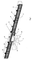
- the device consists of a material measure 10 and a read head 12.
- the material measure 10 and the read head 12 are each represented schematically by a housing.
- the material measure 10 is shown in the drawing in a section of limited linear extent. As explained above, the measuring scale 10 can have a virtually unlimited length.
- the material measure 10 is firmly connected to an object, while the read head 12 is fixedly connected to a second object.
- the two objects are mutually movable, in particular in the longitudinal direction of the measuring scale 10 against each other movable, as in FIG. 2 indicated by a double arrow.
- the measuring scale 10 has an incremental graduation 14, which extends over the entire length of the material measure 10 in the measuring direction, i. the direction of movement extends.
- the incremental graduation 14 is scanned by a scan 16 of the read head 12.
- the incremental graduation 14 and the scan 16 may be formed in a conventional manner optical, inductive or capacitive. Excluded is only a magnetic training of the incremental pitch 14.
- the scan 16 generated in the movement over the incremental pitch 14 in a conventional manner scanning signals that have a sinusoidal shape substantially.
- the sinusoidal form of the scanning signals makes it possible, in a manner known per se, to interpolate the pitch of the incremental graduation 14, so that the resolution can again be improved by more than a factor of 1000 (up to 14 bits) compared to the resolution of the pitch 14 on the order of magnitude.
- the measuring scale 10 permanent magnets 18 which are arranged in the measuring direction, ie in the longitudinal direction of the measuring scale 10 at equidistant intervals.
- the permanent magnets 18 are arranged so that they each facing the read head 12 alternately with its north pole or south pole. In the drawing, the permanent magnets 18 are arranged on the side remote from the reading head 12 of the measuring scale 10. Other arrangements are also possible.
- the incremental graduation 14 is subdivided into segments 20, ie into subsections. Each segment 20 extends from a permanent magnet 18 to the next in the measuring direction permanent magnet 18.
- the segments 20 close gapless and comprise several graduation steps of the incremental pitch 14.
- the permanent magnets 18 generate a magnetic field 22, whose field lines each of a permanent magnet 18th to the following Permanent magnets 18 extend, as in FIG. 2 indicated by arrows.
- the field lines of the magnetic fields 22 thus extend with changing field strength over the length of the segments 20.
- At least one magnetic sensor 24 is arranged, in the illustrated embodiment, three magnetic sensors 24 are arranged spaced apart in the measuring direction.
- the magnetic field 22 of the permanent magnets 18 passes through the non-magnetic incremental graduation 14 and the read head 12.
- the magnetic sensors 24 each detect the magnetic field strength of these magnetic fields 22. Since the magnetic field strength changes over the length of the segment, by means of the magnetic sensors 24, the position of the Read head 12 are determined within the length of the respective segment 20.
- the magnetic sensors 24 may be, for example, magnetoresistive sensors, such as in DE 32 44 891 C2 is described.
- the length of the segments 20, the number of pitch steps of the incremental pitch 14 within the segments 20 and the magnetic sensors 24 are dimensioned such that by measuring the magnetic field strength by means of the magnetic sensors 24, the current position of the read head 12 a certain division step of the incremental pitch 14th can be clearly assigned.
- the spacing of the permanent magnets 18 corresponds at least to the length of the reading head 12.
- a Wieganddraht device is arranged in the read head 12, which consists of a Wiegand wire 26 (pulse wire), which is aligned in the measuring direction, ie in the direction of relative movement and is wound with a coil 28.
- a Wiegand wire 26 pulse wire
- an electric pulse is triggered in the Wieganddraht 26 whose polarity depends on the direction of movement of the read head 12 relative to the material measure 10.
- These voltage pulses are supplied as a segment count pulses of an electronic counter circuit, not shown, which counts these segment counts up or down depending on the direction of movement.
- the respective counter reading is stored in a memory of the electronic evaluation captive. For feeding the counter circuit and for captive storage, the speed-independent energy of the pulses of Wieganddrahtes 26 is stored, so that the read head 12 with the electronic evaluation energy self-sufficient and independent of external energy sources.
- the measuring device is once entered a zero position of the reading head 12 relative to the material measure 10.
- the segments 20 run over by the reading head are counted upwards and downwards by the weighing-wire device 26, 28, depending on the direction of movement.
- the current counter reading is stored permanently. The stored counter reading is therefore at any time, even when restarting after an interruption in operation and possibly a movement of the measuring device during this time, absolutely, before which segment 20, the read head 12 is located.
- the measurement of the magnetic field 22 by the magnetic sensors 24 further indicates absolutely before which pitch step of the incremental graduation 14 within the displayed segment 20 the read head 12 is located. Within this division step, the sample 16 can now again interpolate the exact position with high resolution.
Landscapes
- Physics & Mathematics (AREA)
- General Physics & Mathematics (AREA)
- Transmission And Conversion Of Sensor Element Output (AREA)
Description
Die Erfindung betrifft eine Vorrichtung zur Messung der Relativposition zwischen einer Maßverkörperung und einem Lesekopf.The invention relates to a device for measuring the relative position between a material measure and a read head.
Zur Messung der Relativposition zweier linear oder rotatorisch gegeneinander bewegbarer Objekte ist es bekannt, dem einen Objekt eine Maßverkörperung zuzuordnen, welche durch einen dem zweiten Objekt zugeordneten Lesekopf abgetastet wird. Bei inkrementalen Systemen weist die Maßverkörperung eine inkrementale Teilung mit äquidistanten Marken auf, die bei der Relativbewegung mittels des Lesekopfes gezählt werden. Bei absoluten Systemen weist die Maßverkörperung eine Codierung auf, die durch den Lesekopf gelesen wird und die jeweilige Position angibt. Bei den inkrementalen Systemen muss jeweils eine Ausgangsposition für die Zählung vorgegeben werden, während bei den absoluten Systemen beim Einschalten die Position durch die Codierung unmittelbar abgelesen werden kann.In order to measure the relative position of two linearly or rotationally mutually movable objects, it is known to associate with the one object a material measure which is scanned by a reading head assigned to the second object. For incremental systems, the material measure has an incremental graduation with equidistant marks, which are counted during the relative movement by means of the read head. In absolute systems, the material measure has an encoding which is read by the read head and indicates the respective position. For the incremental systems, a starting position for the count must always be specified, while in the case of the absolute systems, the position can be read directly by the coding when switching on.
Inkrementale Systeme haben den Vorteil, dass die Maßverkörperung auch mit hoher Auflösung relativ einfach hergestellt werden kann. Die Auflösung kann weiter dadurch verbessert werden, dass die bei der Abtastung der periodischen Teilung in der Regel entstehenden sinusförmigen Signale noch interpoliert werden, wodurch die Auflösung um bis zu 2 oder 3 Größenordnungen verbessert werden kann.Incremental systems have the advantage that the material measure can be produced relatively easily even with high resolution. The resolution can be further improved by interpolating the sinusoidal signals which are usually produced during the scanning of the periodic division, whereby the resolution can be improved by up to 2 or 3 orders of magnitude.
Um den Nachteil der fehlenden Absolutpositionen bei dem inkrementalen System zu beseitigen, ist es aus der
Bei absoluten Systemen ist der Messbereich insbesondere bei linearen Meßsystemen begrenzt. Je größer die Messstrecke wird, umso mehr Code-Spuren werden benötigt, um die Absolutposition mit einer ausreichenden Auflösung zu codieren. Diesem Nachteil wird gemäß
Aus der
Der Erfindung liegt die Aufgabe zugrunde, eine Vorrichtung zur Messung der Relativposition zur Verfügung zu stellen, die in kostengünstiger Weise eine hohe Auflösung ermöglicht und praktisch keine Einschränkungen bezüglich der Messstrecke aufweist.The invention has for its object to provide a device for measuring the relative position available, which allows a high resolution in a cost effective manner and has virtually no restrictions with respect to the measuring section.
Die Aufgabe wird erfindungsgemäß gelöst durch eine Vorrichtung mit den Merkmalen des Patentanspruchs 1.The object is achieved by a device having the features of claim 1.
Vorteilhafte Ausführungen der Erfindung sind in den Unteransprüchen angegeben.Advantageous embodiments of the invention are specified in the subclaims.
Die erfindungsgemäße Vorrichtung zur Messung der Relativposition zwischen einer Maßverkörperung und einem Lesekopf weist eine Maßverkörperung und einen Lesekopf auf. Die Maßverkörperung wird einem Objekt fest zugeordnet, während der Lesekopf einem zweiten Objekt fest zugeordnet wird, welches gegenüber dem ersten Objekt relativ bewegbar ist. Die Relativbewegung kann eine lineare Bewegung oder eine rotatorische Bewegung sein. Dementsprechend ist die Maßverkörperung linear oder kreisförmig ausgebildet.The device according to the invention for measuring the relative position between a material measure and a read head has a material measure and a read head. The material measure is permanently assigned to an object, while the read head is permanently assigned to a second object which is relatively movable with respect to the first object. The relative movement may be a linear movement or a rotational movement. Accordingly, the material measure is linear or circular.
Die Maßverkörperung weist eine inkrementale Teilung auf, die in an sich bekannter Weise ausgebildet sein kann. Der Lesekopf weist eine der inkrementalen Teilung entsprechende Abtastung auf, die ebenfalls in an sich bekannter Weise ausgebildet sein kann. Bei der Relativbewegung von Maßverkörperung und Lesekopf erzeugt die Abtastung der inkrementalen Teilung in der Regel etwa sinusförmige Signale, die eine nochmalige Interpolation der Teilungsschritte der inkrementalen Teilung in einer nachgeschalteten elektronischen Auswertung ermöglichen. Die inkrementale Teilung kann eine optisch abgetastete Teilung sein, die eine besonders hohe Auflösung ermöglicht, jedoch mechanisch empfindlich ist. Die inkrementale Teilung kann weiter eine kapazitive Abtastung sein, die zwar nicht mit ganz so hoher Auflösung realisiert werden kann, jedoch äußerst robust ist. Ebenso kann die inkrementale Teilung induktiv abgetastet werden, z.B. nach dem Wirbelstromprinzip, was ebenfalls eine robuste Ausführung und insbesondere eine Ausführung mit hoher Schutzklasse (IP 69 K) ermöglicht. Alle diese Teilungen und deren Abtastung sind an sich bekannter Stand der Technik. Erfindungsgemäß ist lediglich eine magnetische Ausführung der inkrementalen Teile ausgeschlossen.The material measure has an incremental pitch, which may be formed in a conventional manner. The read head has a scan corresponding to the incremental graduation, which scan can also be formed in a manner known per se. In the case of the relative movement of the material measure and read head, the incremental graduation scan generally generates approximately sinusoidal signals, which involve a further interpolation of the incremental graduation steps in a downstream one enable electronic evaluation. The incremental pitch can be an optically scanned pitch that allows for very high resolution but is mechanically sensitive. The incremental pitch may further be a capacitive sample, which, while not capable of very high resolution, is extremely robust. Likewise, the incremental pitch can be scanned inductively, for example according to the eddy current principle, which also allows a robust design and in particular a version with a high degree of protection (IP 69 K). All these divisions and their sampling are known in the art. According to the invention, only a magnetic design of the incremental parts is excluded.
Weiter weist die Maßverkörperung Permanentmagnete auf, die in Messrichtung, d.h. in der Richtung der Relativbewegung, äquidistant angeordnet sind. Die Permanentmagnete definieren lückenlos aneinander anschließende Segmente bzw. Teilabschnitte der inkrementalen Teilung. Das von den jeweils in Messrichtung aufeinander folgenden Permanentmagneten erzeugte Magnetfeld wird durch wenigstens einen Magnetsensor des Lesekopfes erfasst. Dieser Magnetsensor ermittelt in an sich bekannter Weise, wie dies z.B. in der
Schließlich ist der Lesekopf noch mit einer Wieganddraht-Einrichtung (Impulsdraht-Einrichtung) ausgestattet. Diese Wieganddraht-Einrichtung erzeugt beim Überfahren der Permanentmagnete jeweils Segmentzählimpulse, die in einem zugeordneten Zähler je nach Bewegungsrichtung aufwärts oder abwärts gezählt werden. Der Zählerstand gibt somit das Segment der Maßverkörperung an, in welchem sich der Lesekopf ausgehend von einer ursprünglichen Nullposition aktuell befindet. Der Zähler speichert den jeweiligen Zählerstand unverlierbar, so dass auch bei einer Betriebsunterbrechung der jeweilige Zählerstand und damit die absolute Position des Segments, in welchem sich der Lesekopf aktuell befindet, erhalten bleibt. Um die Speicherschaltung von äußeren Energiequellen unabhängig zu machen, was für eine unverlierbare Speicherung wichtig ist, kann die Zählerschaltung mit dem Speicher durch eine Batterie gespeist werden. Vorteilhaft ist es, wenn die Energie der Zählimpulse der Wieganddraht-Einrichtung zur Speisung der Zählerschaltung und des Speichers genutzt wird, wie dies ebenfalls in der
Die erfindungsgemäße Vorrichtung weist wesentliche Vorteile auf:
- Die Messstrecke der Relativbewegung ist praktisch unbeschränkt. Bei einer linearen Vorrichtung können somit auch sehr große Längen gemessen werden. Bei rotatorischen Systemen kann die Messung über viele Umdrehungen erfolgen. Der Aufwand der Messvorrichtung ist weitgehend von der Länge der Messstrecke unabhängig, so dass die Vorrichtung insbesondere bei großen Messstrecken äußerst kostengünstig ist.
- The measuring path of the relative movement is virtually unlimited. In a linear device thus very large lengths can be measured. In rotary systems, the measurement can be made over many revolutions. The expense of the measuring device is largely independent of the length of the measuring section, so that the device is extremely cost-effective, especially for large measuring distances.
Die Auflösung der Messvorrichtung ist durch die inkrementale Teilung und deren Interpolation bestimmt, so dass unabhängig von der Länge der Messstrecke die hohe Auflösung bekannter Vorrichtungen erreicht werden kann.The resolution of the measuring device is determined by the incremental graduation and its interpolation, so that the high resolution of known devices can be achieved, regardless of the length of the measuring path.
Die aktuelle Position kann absolut ermittelt werden, indem einerseits die Segmente gezählt und der Zählerstand unverlierbar gespeichert wird und andererseits die Position des Lesekopfes innerhalb eines Segmentes über die Magnetsensoren absolut einem Teilungsschritt der inkrementalen Teilung zugeordnet werden kann.The current position can be determined absolutely, on the one hand, by counting the segments and by memorably saving the counter reading and, on the other hand, by assigning the position of the read head within a segment via the magnetic sensors to absolutely one incremental graduation increment.
Während der Positionsmessung zählt die Zähleinrichtung mittels der von der Wieganddraht-Einrichtung erzeugten Segmentzählimpulse die von dem Lesekopf in Vorwärts- bzw. Rückwärtsrichtung überfahrenen Permanentmagnete und speichert unverlierbar den Zählerstand. Dieser Zählerstand gibt somit ausgehend von einem anfangs vorgegebenen Nullpunkt jederzeit, d.h. insbesondere auch nach einer Betriebsunterbrechung und gegebenenfalls einem Verfahren in dieser spannungslosen Zeit, absolut an, in welchem Segment sich der Lesekopf befindet. Die Länge der Messstrecke, d.h. die Anzahl der Segmente, unterliegt dabei praktisch keiner Beschränkung. Innerhalb des jeweiligen Segmentes gibt die Abtastung des Magnetfeldes der Permanentmagnete durch die Magnetsensoren des Lesekopfes eine absolute Positionsangabe, innerhalb welchen Teilungsschrittes der inkrementalen Teilung innerhalb des jeweiligen Segmentes sich der Lesekopf befindet. Auch diese Positionsinformation steht beim Einschalten der Vorrichtung absolut zur Verfügung. Innerhalb des Teilungsschrittes wird die Position nochmals durch Interpolation der Abtastsignale mit einer höheren Auflösung gemessen.During the position measurement, the counting means counts the generated by the Wieganddraht device segment counting pulses of the read head in the forward or reverse direction over run permanent magnets and captively stores the count. Starting from an initially predetermined zero point at all times, that is to say in particular after an interruption in operation and, if appropriate, a method in this voltage-free time, this counter reading therefore indicates absolutely in which segment the read head is located. The length of the measuring section, ie the number of segments, is subject to virtually no restriction. Within the respective segment, the scanning of the magnetic field of the permanent magnets by the magnetic sensors of the reading head gives an absolute position indication within which division step of the incremental graduation within the respective segment the read head is located. This position information is absolutely available when switching on the device. Within the division step, the position is again measured by interpolating the scanning signals with a higher resolution.
Die erfindungsgemäße Vorrichtung vereinigt somit die Vorteile der mit relativ einfachen Mitteln erreichbaren hohen Auflösung einer inkrementalen Teilung mit den Vorteilen einer absoluten Positionsbestimmung, ohne dass der Messbereich aufgrund der Kosten oder der Konstruktion einer Beschränkung unterliegt.The device according to the invention thus combines the advantages of the achievable with relatively simple means high resolution incremental graduation with the advantages of an absolute position determination, without the measuring range is subject to a restriction due to the cost or design.
Im Folgenden wird die Erfindung anhand eines in der Zeichnung dargestellten Ausführungsbeispiels näher erläutert. Es zeigen
- Figur 1
- schematisch eine Ansicht der Vorrichtung und
- Figur 2
- eine schematische Draufsicht auf die Vorrichtung.
- FIG. 1
- schematically a view of the device and
- FIG. 2
- a schematic plan view of the device.
In der Zeichnung ist die Erfindung in einer Ausführung als lineare Messvorrichtung dargestellt. Eine analoge Ausbildung als rotatorisches Messsystem ergibt sich für den Fachmann in selbstverständlicher Weise.In the drawing, the invention is shown in an embodiment as a linear measuring device. An analog training as rotary measuring system results for the expert in a natural way.
Die Vorrichtung besteht aus einer Maßverkörperung 10 und einem Lesekopf 12. In der Zeichnung sind die Maßverkörperung 10 und der Lesekopf 12 jeweils schematisch durch ein Gehäuse dargestellt. Die Maßverkörperung 10 ist in der Zeichnung in einem Abschnitt begrenzter linearer Ausdehnung dargestellt. Wie vorstehend erläutert kann die Maßverkörperung 10 eine praktisch unbegrenzte Länge aufweisen. Die Maßverkörperung 10 ist mit einem Objekt fest verbunden, während der Lesekopf 12 mit einem zweiten Objekt fest verbunden ist. Die beiden Objekte sind gegeneinander bewegbar, insbesondere in Längsrichtung der Maßverkörperung 10 gegeneinander bewegbar, wie dies in
Die Maßverkörperung 10 weist eine inkrementale Teilung 14 auf, die sich über die gesamte Länge der Maßverkörperung 10 in der Messrichtung, d.h. der Bewegungsrichtung erstreckt. Die inkrementale Teilung 14 wird durch eine Abtastung 16 des Lesekopfes 12 abgetastet. Die inkrementale Teilung 14 und die Abtastung 16 können in an sich bekannter Weise optisch, induktiv oder kapazitiv ausgebildet sein. Ausgeschlossen ist lediglich eine magnetische Ausbildung der inkrementalen Teilung 14. Die Abtastung 16 erzeugt bei der Bewegung über die inkrementale Teilung 14 in an sich bekannter Weise Abtastsignale, die im Wesentlichen einen sinusförmigen Verlauf haben. Die Sinusform der Abtastsignale ermöglicht in an sich bekannter Weise eine Interpolation des Teilungsabstandes der inkrementalen Teilung 14, so dass die Auflösung nochmals gegenüber der Auflösung der Teilung 14 um mehr als einen Faktor 1000 (bis zu 14 bit) in der Größenordnung verbessert werden kann.The measuring scale 10 has an
Weiter weist die Maßverkörperung 10 Permanentmagnete 18 auf, die in Messrichtung, d.h. in Längsrichtung der Maßverkörperung 10 in äquidistanten Abständen angeordnet sind. Die Permanentmagnete 18 sind dabei so angeordnet, dass sie jeweils alternierend mit ihrem Nordpol oder Südpol dem Lesekopf 12 zugewandt sind. In der Zeichnung sind die Permanentmagnete 18 auf der von dem Lesekopf 12 abgewandten Seite der Maßverkörperung 10 angeordnet. Andere Anordnungen sind ebenfalls möglich. Durch die Permanentmagnete 18 wird die inkrementale Teilung 14 in Segmente 20, d.h. in Teilabschnitte unterteilt. Jedes Segment 20 erstreckt sich jeweils von einem Permanentmagneten 18 bis zu dem in Messrichtung nächsten Permanentmagneten 18. Die Segmente 20 schließen lückenlos aneinander an und umfassen mehrere Teilungsschritte der inkrementalen Teilung 14. Die Permanentmagnete 18 erzeugen ein Magnetfeld 22, dessen Feldlinien jeweils von einem Permanentmagneten 18 zu dem folgenden Permanentmagneten 18 verlaufen, wie in
In dem Lesekopf 12 ist wenigstens ein Magnetsensor 24 angeordnet, im dargestellten Ausführungsbeispiel sind drei Magnetsensoren 24 in Messrichtung beabstandet angeordnet. Das Magnetfeld 22 der Permanentmagnete 18 durchsetzt die nicht magnetische inkrementale Teilung 14 und den Lesekopf 12. Die Magnetsensoren 24 erfassen jeweils die magnetische Feldstärke dieser Magnetfelder 22. Da sich die magnetische Feldstärke über die Länge des Segmentes ändert, kann mittels der Magnetsensoren 24 die Position des Lesekopfes 12 innerhalb der Länge des jeweiligen Segmentes 20 bestimmt werden. Die Magnetsensoren 24 können beispielsweise magnetoresistive Sensoren sein, wie dies z.B. in
Schließlich ist in dem Lesekopf 12 noch eine Wieganddraht-Einrichtung angeordnet, die aus einem Wieganddraht 26 (Impulsdraht) besteht, der in der Messrichtung, d.h. in der Richtung der Relativbewegung ausgerichtet ist und mit einer Spule 28 umwickelt ist. Wenn der Lesekopf 12 bei der Relativbewegung von Lesekopf 12 und Maßverkörperung 10 über einen der Permanentmagnete 18 hinwegfährt, wird in dem Wieganddraht 26 ein elektrischer Impuls ausgelöst, dessen Polarität von der Bewegungsrichtung des Lesekopfes 12 gegenüber der Maßverkörperung 10 abhängt. Diese Spannungsimpulse werden als Segmentzählimpulse einer nicht dargestellten elektronischen Zählschaltung zugeführt, die diese Segmentzählimpulse je nach Bewegungsrichtung aufwärts oder abwärts zählt. Der jeweilige Zählerstand wird in einem Speicher der elektronischen Auswertung unverlierbar gespeichert. Zur Speisung der Zählerschaltung und zur unverlierbaren Speicherung wird die geschwindigkeitsunabhängige Energie der Impulse des Wieganddrahtes 26 gespeichert, so dass der Lesekopf 12 mit der elektronischen Auswertung energieautark und von externen Energiequellen unabhängig ist.Finally, a Wieganddraht device is arranged in the read
Der Messvorrichtung wird einmalig eine Nullposition des Lesekopfes 12 gegenüber der Maßverkörperung 10 eingegeben. Bewegt sich der Lesekopf 12 relativ zu der Maßverkörperung 10, so werden die von dem Lesekopf überfahrenen Segmente 20 durch die Wieganddraht-Einrichtung 26, 28 je nach Bewegungsrichtung aufwärts und abwärts gezählt. Der aktuelle Zählerstand wird unverlierbar abgespeichert. Der abgespeicherte Zählerstand gibt somit jederzeit, auch bei Wiedereinschalten nach einer Betriebsunterbrechung und gegebenenfalls einer Bewegung der Messvorrichtung während dieser Zeit, absolut an, vor welchem Segment 20 sich der Lesekopf 12 befindet. Die Messung des Magnetfeldes 22 durch die Magnetsensoren 24 gibt weiter absolut an, vor welchem Teilungsschritt der inkrementalen Teilung 14 innerhalb des angezeigten Segmentes 20 sich der Lesekopf 12 befindet. Innerhalb dieses Teilungsschrittes kann nun die Abtastung 16 nochmals mit hoher Auflösung die exakte Position interpolieren.The measuring device is once entered a zero position of the reading
- 1010
- MaßverkörperungMeasuring standard
- 1212
- Lesekopfread head
- 1414
- inkrementale Teilungincremental division
- 1616
- Abtastungscan
- 1818
- Permanentmagnetepermanent magnets
- 2020
- Segmentesegments
- 2222
- Magnetfeldmagnetic field
- 2424
- Magnetsensormagnetic sensor
- 2626
- WieganddrahtWiegand
- 2828
- SpuleKitchen sink
Claims (9)
- A device for measuring the relative position between a measuring scale (10) and a reading head (12) comprising- a measuring scale (10) having an indexing (14),- a read head (12) which scans the indexing (14) in a nonmagnetic way at a high resolution, the measuring scale (10) comprises in the measuring direction equidistantly arranged permanent magnets (18) which define mutually adjacent segments (20) of the indexing (14), and wherein a Wiegand wire means (26, 28) of the reading head (12) generates segment count pulses when passing over the permanent magnets (18), the segment counts are non-losable counted in a memory,characterized
in that the indexing (14) is an incremental indexing,
in that the segments (20) comprise a plurality of indexing steps of the incremental indexing (14),
in that the magnetic field (22) generated by each successive permanent magnet (18) is detected by at least one magnetic sensor (24) of the reading head (12),
in that the position of the read head (12) is associated with a respective indexing step of the incremental indexing (14) within the segment (20) fixed by these permanent magnets (18) by the magnitude of the detected magnetic field (22) and
in that the signals of the sampling (16) of the incremental indexing (14) are evaluated for interpolation of the indexing steps. - Device according to claim 1, wherein said incremental indexing (14) is capacitively or inductively or optically scanned.
- Device according to claim 1 or 2, wherein the magnetic sensors (24) are magnetoresistive sensors.
- Device according to claim 1, wherein the memory counts the segment count pules upwardly or downwardly depending on the direction of relative movement.
- Device according to claim 1, wherein the counting circuit and the memory are independent of external power sources.
- Device according to claim 5, wherein the counter circuit and the memory are powered by a battery.
- Device according to claim 5, wherein the counter circuit and the memory are powered by the energy of the segment count pulses.
- Device according to one of the preceding claims, in which the permanent magnets (18) with alternating polarity follow one after the other.
- Device according to one of the preceding claims, in which the distance of the permanent magnets (18) in the measuring direction is at least equal to the length of the read head (12) in the measuring direction.
Priority Applications (2)
| Application Number | Priority Date | Filing Date | Title |
|---|---|---|---|
| EP08015103.8A EP2159549B1 (en) | 2008-08-27 | 2008-08-27 | Device for measuring the relative position between a material measure and a read head |
| US12/461,497 US7908762B2 (en) | 2008-08-27 | 2009-08-13 | Device for measuring the relative position of a material measure and a reading head |
Applications Claiming Priority (1)
| Application Number | Priority Date | Filing Date | Title |
|---|---|---|---|
| EP08015103.8A EP2159549B1 (en) | 2008-08-27 | 2008-08-27 | Device for measuring the relative position between a material measure and a read head |
Publications (2)
| Publication Number | Publication Date |
|---|---|
| EP2159549A1 EP2159549A1 (en) | 2010-03-03 |
| EP2159549B1 true EP2159549B1 (en) | 2015-10-07 |
Family
ID=40139138
Family Applications (1)
| Application Number | Title | Priority Date | Filing Date |
|---|---|---|---|
| EP08015103.8A Not-in-force EP2159549B1 (en) | 2008-08-27 | 2008-08-27 | Device for measuring the relative position between a material measure and a read head |
Country Status (2)
| Country | Link |
|---|---|
| US (1) | US7908762B2 (en) |
| EP (1) | EP2159549B1 (en) |
Families Citing this family (6)
| Publication number | Priority date | Publication date | Assignee | Title |
|---|---|---|---|---|
| US10969214B2 (en) | 2013-12-31 | 2021-04-06 | Joral Llc | Position sensor with Wiegand wire, position magnet(s) and reset magnet |
| US9803998B1 (en) | 2013-12-31 | 2017-10-31 | Joral Llc | Absolute position sensor with fine resolution |
| EP3325914B1 (en) * | 2015-07-23 | 2020-03-18 | Actimesure | Feeler device for geometrically controlling parts |
| CN111480285B (en) * | 2018-06-28 | 2022-08-19 | 西门子股份公司 | Electronic seal device, motor assembly and electronic seal verification method |
| US11105608B2 (en) * | 2019-10-24 | 2021-08-31 | Pixart Imaging Inc. | Optical positioning system and operating method thereof |
| US20220214452A1 (en) * | 2020-08-07 | 2022-07-07 | Woodward, Inc. | Ratio metric position sensor and control system |
Citations (2)
| Publication number | Priority date | Publication date | Assignee | Title |
|---|---|---|---|---|
| US6002250A (en) * | 1996-05-13 | 1999-12-14 | Mitutoyo Corporation | Electronic linear scale using a self-contained, low-power inductive position transducer |
| WO2003012972A1 (en) * | 2001-07-20 | 2003-02-13 | Siemens Aktiengesellschaft | Measuring device and method for controlling electric motors |
Family Cites Families (11)
| Publication number | Priority date | Publication date | Assignee | Title |
|---|---|---|---|---|
| JPS5866001A (en) * | 1981-10-15 | 1983-04-20 | Sony Magnescale Inc | Magnetic scale device |
| AT404300B (en) * | 1992-02-20 | 1998-10-27 | Rsf Elektronik Gmbh | ENCODER |
| WO2002025217A1 (en) * | 2000-09-25 | 2002-03-28 | Kabushiki Kaisha Tokai Rika Denki Seisakusho | Rotating angle detector |
| US6922907B2 (en) * | 2001-04-05 | 2005-08-02 | Anton Rodi | Measuring system for recording absolute angular or position values |
| US6912797B2 (en) * | 2001-04-05 | 2005-07-05 | Anton Rodi | Measuring system for recording absolute angular or position values |
| JP4518833B2 (en) * | 2004-02-03 | 2010-08-04 | 矢崎総業株式会社 | Rotation angle sensor |
| GB0415141D0 (en) * | 2004-07-06 | 2004-08-11 | Renishaw Plc | Scale reading apparatus |
| DE202004014849U1 (en) * | 2004-09-23 | 2005-02-03 | Trw Automotive Safety Systems Gmbh | Device for determining an absolute angle of rotation |
| DE102005047009A1 (en) * | 2005-09-30 | 2007-04-05 | Bosch Rexroth Mechatronics Gmbh | Absolute position measuring system |
| DE102006017865B4 (en) * | 2006-04-13 | 2012-04-12 | Sick Stegmann Gmbh | Device for measuring the absolute position of a test object |
| US7971487B2 (en) * | 2008-05-02 | 2011-07-05 | Carlen Controls, Inc. | Linear position transducer with wireless read head |
-
2008
- 2008-08-27 EP EP08015103.8A patent/EP2159549B1/en not_active Not-in-force
-
2009
- 2009-08-13 US US12/461,497 patent/US7908762B2/en not_active Expired - Fee Related
Patent Citations (2)
| Publication number | Priority date | Publication date | Assignee | Title |
|---|---|---|---|---|
| US6002250A (en) * | 1996-05-13 | 1999-12-14 | Mitutoyo Corporation | Electronic linear scale using a self-contained, low-power inductive position transducer |
| WO2003012972A1 (en) * | 2001-07-20 | 2003-02-13 | Siemens Aktiengesellschaft | Measuring device and method for controlling electric motors |
Also Published As
| Publication number | Publication date |
|---|---|
| US20100050455A1 (en) | 2010-03-04 |
| US7908762B2 (en) | 2011-03-22 |
| EP2159549A1 (en) | 2010-03-03 |
Similar Documents
| Publication | Publication Date | Title |
|---|---|---|
| EP2221587B1 (en) | Absolute magnetic positioner | |
| EP2561319B1 (en) | Position detecting device and method for producing a marking arrangement for a position detecting device | |
| EP2182330B1 (en) | Positioning / distance measuring system with encoded measurement body | |
| EP2159549B1 (en) | Device for measuring the relative position between a material measure and a read head | |
| EP2533018B1 (en) | Linear distance measuring system | |
| EP1662232A1 (en) | Linear position sensor | |
| EP3803278B1 (en) | Absolute encoder | |
| DE20311861U1 (en) | Device for position and / or length determination | |
| EP3179216A1 (en) | Absolute measurement length measuring system and method of operating the same | |
| DE102006017865A1 (en) | Measuring object absolute position measuring device, has sensor head with sampling unit reading absolute coding of partitions of solid measure and sensor that detects permanent magnetic markings | |
| EP1236968A2 (en) | Magnetic length measuring device | |
| DE202008013715U1 (en) | Device for determining the relative position of two mutually movable objects | |
| DE102011000486A1 (en) | Coded magnetostrictive absolute position measuring system, particularly length measuring system for determining position of two objects, comprises magnetic code carrier which is arranged at object | |
| DE102008010095A1 (en) | Measuring standard, measuring device and measuring method for absolute position determination | |
| EP1321743B1 (en) | Absolute length measuring system with a measuring rod moving with respect to mutually spaced length sensors | |
| EP2116814B1 (en) | Measuring device for calculating a position and/or a speed | |
| DE102013222197A1 (en) | Position measuring device | |
| DE19632656A1 (en) | Absolute magnetic encoding | |
| DE102018118477A1 (en) | Absolute encoders | |
| EP3764063B1 (en) | Method of determining the absolute position of a carriage of an electric linear direct drive and electric linear direct drive | |
| EP2869035A1 (en) | Position measuring system and control method for linear motors linked together | |
| DE3926328A1 (en) | DEVICE FOR MEASURING LENGTHS, ANGLES AND THE LIKE | |
| DE102012213717A1 (en) | Inkrementalwegsensor | |
| DE102018203409A1 (en) | Linear motion device and method | |
| EP3021088B1 (en) | Incremental length measuring system and method of operating the same |
Legal Events
| Date | Code | Title | Description |
|---|---|---|---|
| PUAI | Public reference made under article 153(3) epc to a published international application that has entered the european phase |
Free format text: ORIGINAL CODE: 0009012 |
|
| 17P | Request for examination filed |
Effective date: 20090227 |
|
| AK | Designated contracting states |
Kind code of ref document: A1 Designated state(s): AT BE BG CH CY CZ DE DK EE ES FI FR GB GR HR HU IE IS IT LI LT LU LV MC MT NL NO PL PT RO SE SI SK TR |
|
| AX | Request for extension of the european patent |
Extension state: AL BA MK RS |
|
| AKX | Designation fees paid |
Designated state(s): AT BE BG CH CY CZ DE DK EE ES FI FR GB GR HR HU IE IS IT LI LT LU LV MC MT NL NO PL PT RO SE SI SK TR |
|
| 17Q | First examination report despatched |
Effective date: 20121025 |
|
| GRAP | Despatch of communication of intention to grant a patent |
Free format text: ORIGINAL CODE: EPIDOSNIGR1 |
|
| INTG | Intention to grant announced |
Effective date: 20150520 |
|
| GRAS | Grant fee paid |
Free format text: ORIGINAL CODE: EPIDOSNIGR3 |
|
| GRAA | (expected) grant |
Free format text: ORIGINAL CODE: 0009210 |
|
| AK | Designated contracting states |
Kind code of ref document: B1 Designated state(s): AT BE BG CH CY CZ DE DK EE ES FI FR GB GR HR HU IE IS IT LI LT LU LV MC MT NL NO PL PT RO SE SI SK TR |
|
| REG | Reference to a national code |
Ref country code: GB Ref legal event code: FG4D Free format text: NOT ENGLISH |
|
| REG | Reference to a national code |
Ref country code: AT Ref legal event code: REF Ref document number: 754019 Country of ref document: AT Kind code of ref document: T Effective date: 20151015 Ref country code: CH Ref legal event code: EP |
|
| REG | Reference to a national code |
Ref country code: IE Ref legal event code: FG4D Free format text: LANGUAGE OF EP DOCUMENT: GERMAN |
|
| REG | Reference to a national code |
Ref country code: DE Ref legal event code: R096 Ref document number: 502008013451 Country of ref document: DE |
|
| REG | Reference to a national code |
Ref country code: NL Ref legal event code: MP Effective date: 20151007 |
|
| REG | Reference to a national code |
Ref country code: LT Ref legal event code: MG4D |
|
| PG25 | Lapsed in a contracting state [announced via postgrant information from national office to epo] |
Ref country code: IS Free format text: LAPSE BECAUSE OF FAILURE TO SUBMIT A TRANSLATION OF THE DESCRIPTION OR TO PAY THE FEE WITHIN THE PRESCRIBED TIME-LIMIT Effective date: 20160207 Ref country code: IT Free format text: LAPSE BECAUSE OF FAILURE TO SUBMIT A TRANSLATION OF THE DESCRIPTION OR TO PAY THE FEE WITHIN THE PRESCRIBED TIME-LIMIT Effective date: 20151007 Ref country code: NO Free format text: LAPSE BECAUSE OF FAILURE TO SUBMIT A TRANSLATION OF THE DESCRIPTION OR TO PAY THE FEE WITHIN THE PRESCRIBED TIME-LIMIT Effective date: 20160107 Ref country code: HR Free format text: LAPSE BECAUSE OF FAILURE TO SUBMIT A TRANSLATION OF THE DESCRIPTION OR TO PAY THE FEE WITHIN THE PRESCRIBED TIME-LIMIT Effective date: 20151007 Ref country code: NL Free format text: LAPSE BECAUSE OF FAILURE TO SUBMIT A TRANSLATION OF THE DESCRIPTION OR TO PAY THE FEE WITHIN THE PRESCRIBED TIME-LIMIT Effective date: 20151007 Ref country code: LT Free format text: LAPSE BECAUSE OF FAILURE TO SUBMIT A TRANSLATION OF THE DESCRIPTION OR TO PAY THE FEE WITHIN THE PRESCRIBED TIME-LIMIT Effective date: 20151007 Ref country code: ES Free format text: LAPSE BECAUSE OF FAILURE TO SUBMIT A TRANSLATION OF THE DESCRIPTION OR TO PAY THE FEE WITHIN THE PRESCRIBED TIME-LIMIT Effective date: 20151007 |
|
| PG25 | Lapsed in a contracting state [announced via postgrant information from national office to epo] |
Ref country code: PT Free format text: LAPSE BECAUSE OF FAILURE TO SUBMIT A TRANSLATION OF THE DESCRIPTION OR TO PAY THE FEE WITHIN THE PRESCRIBED TIME-LIMIT Effective date: 20160208 Ref country code: PL Free format text: LAPSE BECAUSE OF FAILURE TO SUBMIT A TRANSLATION OF THE DESCRIPTION OR TO PAY THE FEE WITHIN THE PRESCRIBED TIME-LIMIT Effective date: 20151007 Ref country code: FI Free format text: LAPSE BECAUSE OF FAILURE TO SUBMIT A TRANSLATION OF THE DESCRIPTION OR TO PAY THE FEE WITHIN THE PRESCRIBED TIME-LIMIT Effective date: 20151007 Ref country code: GR Free format text: LAPSE BECAUSE OF FAILURE TO SUBMIT A TRANSLATION OF THE DESCRIPTION OR TO PAY THE FEE WITHIN THE PRESCRIBED TIME-LIMIT Effective date: 20160108 Ref country code: SE Free format text: LAPSE BECAUSE OF FAILURE TO SUBMIT A TRANSLATION OF THE DESCRIPTION OR TO PAY THE FEE WITHIN THE PRESCRIBED TIME-LIMIT Effective date: 20151007 Ref country code: LV Free format text: LAPSE BECAUSE OF FAILURE TO SUBMIT A TRANSLATION OF THE DESCRIPTION OR TO PAY THE FEE WITHIN THE PRESCRIBED TIME-LIMIT Effective date: 20151007 |
|
| REG | Reference to a national code |
Ref country code: DE Ref legal event code: R097 Ref document number: 502008013451 Country of ref document: DE |
|
| PG25 | Lapsed in a contracting state [announced via postgrant information from national office to epo] |
Ref country code: CZ Free format text: LAPSE BECAUSE OF FAILURE TO SUBMIT A TRANSLATION OF THE DESCRIPTION OR TO PAY THE FEE WITHIN THE PRESCRIBED TIME-LIMIT Effective date: 20151007 |
|
| PLBE | No opposition filed within time limit |
Free format text: ORIGINAL CODE: 0009261 |
|
| STAA | Information on the status of an ep patent application or granted ep patent |
Free format text: STATUS: NO OPPOSITION FILED WITHIN TIME LIMIT |
|
| PG25 | Lapsed in a contracting state [announced via postgrant information from national office to epo] |
Ref country code: RO Free format text: LAPSE BECAUSE OF FAILURE TO SUBMIT A TRANSLATION OF THE DESCRIPTION OR TO PAY THE FEE WITHIN THE PRESCRIBED TIME-LIMIT Effective date: 20151007 Ref country code: DK Free format text: LAPSE BECAUSE OF FAILURE TO SUBMIT A TRANSLATION OF THE DESCRIPTION OR TO PAY THE FEE WITHIN THE PRESCRIBED TIME-LIMIT Effective date: 20151007 Ref country code: SK Free format text: LAPSE BECAUSE OF FAILURE TO SUBMIT A TRANSLATION OF THE DESCRIPTION OR TO PAY THE FEE WITHIN THE PRESCRIBED TIME-LIMIT Effective date: 20151007 Ref country code: EE Free format text: LAPSE BECAUSE OF FAILURE TO SUBMIT A TRANSLATION OF THE DESCRIPTION OR TO PAY THE FEE WITHIN THE PRESCRIBED TIME-LIMIT Effective date: 20151007 |
|
| 26N | No opposition filed |
Effective date: 20160708 |
|
| PG25 | Lapsed in a contracting state [announced via postgrant information from national office to epo] |
Ref country code: SI Free format text: LAPSE BECAUSE OF FAILURE TO SUBMIT A TRANSLATION OF THE DESCRIPTION OR TO PAY THE FEE WITHIN THE PRESCRIBED TIME-LIMIT Effective date: 20151007 |
|
| PG25 | Lapsed in a contracting state [announced via postgrant information from national office to epo] |
Ref country code: BE Free format text: LAPSE BECAUSE OF NON-PAYMENT OF DUE FEES Effective date: 20160831 |
|
| PG25 | Lapsed in a contracting state [announced via postgrant information from national office to epo] |
Ref country code: MC Free format text: LAPSE BECAUSE OF FAILURE TO SUBMIT A TRANSLATION OF THE DESCRIPTION OR TO PAY THE FEE WITHIN THE PRESCRIBED TIME-LIMIT Effective date: 20151007 |
|
| REG | Reference to a national code |
Ref country code: CH Ref legal event code: PL |
|
| GBPC | Gb: european patent ceased through non-payment of renewal fee |
Effective date: 20160827 |
|
| PG25 | Lapsed in a contracting state [announced via postgrant information from national office to epo] |
Ref country code: CH Free format text: LAPSE BECAUSE OF NON-PAYMENT OF DUE FEES Effective date: 20160831 Ref country code: LI Free format text: LAPSE BECAUSE OF NON-PAYMENT OF DUE FEES Effective date: 20160831 |
|
| REG | Reference to a national code |
Ref country code: FR Ref legal event code: ST Effective date: 20170428 |
|
| REG | Reference to a national code |
Ref country code: IE Ref legal event code: MM4A |
|
| PG25 | Lapsed in a contracting state [announced via postgrant information from national office to epo] |
Ref country code: IE Free format text: LAPSE BECAUSE OF NON-PAYMENT OF DUE FEES Effective date: 20160827 Ref country code: GB Free format text: LAPSE BECAUSE OF NON-PAYMENT OF DUE FEES Effective date: 20160827 Ref country code: FR Free format text: LAPSE BECAUSE OF NON-PAYMENT OF DUE FEES Effective date: 20160831 |
|
| PG25 | Lapsed in a contracting state [announced via postgrant information from national office to epo] |
Ref country code: LU Free format text: LAPSE BECAUSE OF NON-PAYMENT OF DUE FEES Effective date: 20160827 |
|
| REG | Reference to a national code |
Ref country code: AT Ref legal event code: MM01 Ref document number: 754019 Country of ref document: AT Kind code of ref document: T Effective date: 20160827 |
|
| PG25 | Lapsed in a contracting state [announced via postgrant information from national office to epo] |
Ref country code: AT Free format text: LAPSE BECAUSE OF NON-PAYMENT OF DUE FEES Effective date: 20160827 |
|
| PG25 | Lapsed in a contracting state [announced via postgrant information from national office to epo] |
Ref country code: HU Free format text: LAPSE BECAUSE OF FAILURE TO SUBMIT A TRANSLATION OF THE DESCRIPTION OR TO PAY THE FEE WITHIN THE PRESCRIBED TIME-LIMIT; INVALID AB INITIO Effective date: 20080827 Ref country code: CY Free format text: LAPSE BECAUSE OF FAILURE TO SUBMIT A TRANSLATION OF THE DESCRIPTION OR TO PAY THE FEE WITHIN THE PRESCRIBED TIME-LIMIT Effective date: 20151007 |
|
| PG25 | Lapsed in a contracting state [announced via postgrant information from national office to epo] |
Ref country code: TR Free format text: LAPSE BECAUSE OF FAILURE TO SUBMIT A TRANSLATION OF THE DESCRIPTION OR TO PAY THE FEE WITHIN THE PRESCRIBED TIME-LIMIT Effective date: 20151007 Ref country code: MT Free format text: LAPSE BECAUSE OF FAILURE TO SUBMIT A TRANSLATION OF THE DESCRIPTION OR TO PAY THE FEE WITHIN THE PRESCRIBED TIME-LIMIT Effective date: 20151007 |
|
| PG25 | Lapsed in a contracting state [announced via postgrant information from national office to epo] |
Ref country code: BG Free format text: LAPSE BECAUSE OF FAILURE TO SUBMIT A TRANSLATION OF THE DESCRIPTION OR TO PAY THE FEE WITHIN THE PRESCRIBED TIME-LIMIT Effective date: 20151007 |
|
| REG | Reference to a national code |
Ref country code: DE Ref legal event code: R082 Ref document number: 502008013451 Country of ref document: DE Ref country code: DE Ref legal event code: R081 Ref document number: 502008013451 Country of ref document: DE Owner name: SICK AG, DE Free format text: FORMER OWNER: SICK STEGMANN GMBH, 78166 DONAUESCHINGEN, DE |
|
| PGFP | Annual fee paid to national office [announced via postgrant information from national office to epo] |
Ref country code: DE Payment date: 20220822 Year of fee payment: 15 |
|
| REG | Reference to a national code |
Ref country code: DE Ref legal event code: R119 Ref document number: 502008013451 Country of ref document: DE |
|
| PG25 | Lapsed in a contracting state [announced via postgrant information from national office to epo] |
Ref country code: DE Free format text: LAPSE BECAUSE OF NON-PAYMENT OF DUE FEES Effective date: 20240301 |