EP2868969A1 - Burner - Google Patents
Burner Download PDFInfo
- Publication number
- EP2868969A1 EP2868969A1 EP13813164.4A EP13813164A EP2868969A1 EP 2868969 A1 EP2868969 A1 EP 2868969A1 EP 13813164 A EP13813164 A EP 13813164A EP 2868969 A1 EP2868969 A1 EP 2868969A1
- Authority
- EP
- European Patent Office
- Prior art keywords
- oxygen
- pulverized coal
- containing gas
- nozzle
- supply pipe
- Prior art date
- Legal status (The legal status is an assumption and is not a legal conclusion. Google has not performed a legal analysis and makes no representation as to the accuracy of the status listed.)
- Granted
Links
Images



Classifications
-
- F—MECHANICAL ENGINEERING; LIGHTING; HEATING; WEAPONS; BLASTING
- F23—COMBUSTION APPARATUS; COMBUSTION PROCESSES
- F23D—BURNERS
- F23D1/00—Burners for combustion of pulverulent fuel
- F23D1/02—Vortex burners, e.g. for cyclone-type combustion apparatus
-
- F—MECHANICAL ENGINEERING; LIGHTING; HEATING; WEAPONS; BLASTING
- F23—COMBUSTION APPARATUS; COMBUSTION PROCESSES
- F23C—METHODS OR APPARATUS FOR COMBUSTION USING FLUID FUEL OR SOLID FUEL SUSPENDED IN A CARRIER GAS OR AIR
- F23C7/00—Combustion apparatus characterised by arrangements for air supply
- F23C7/02—Disposition of air supply not passing through burner
-
- F—MECHANICAL ENGINEERING; LIGHTING; HEATING; WEAPONS; BLASTING
- F23—COMBUSTION APPARATUS; COMBUSTION PROCESSES
- F23K—FEEDING FUEL TO COMBUSTION APPARATUS
- F23K3/00—Feeding or distributing of lump or pulverulent fuel to combustion apparatus
- F23K3/02—Pneumatic feeding arrangements, i.e. by air blast
-
- F—MECHANICAL ENGINEERING; LIGHTING; HEATING; WEAPONS; BLASTING
- F23—COMBUSTION APPARATUS; COMBUSTION PROCESSES
- F23L—SUPPLYING AIR OR NON-COMBUSTIBLE LIQUIDS OR GASES TO COMBUSTION APPARATUS IN GENERAL ; VALVES OR DAMPERS SPECIALLY ADAPTED FOR CONTROLLING AIR SUPPLY OR DRAUGHT IN COMBUSTION APPARATUS; INDUCING DRAUGHT IN COMBUSTION APPARATUS; TOPS FOR CHIMNEYS OR VENTILATING SHAFTS; TERMINALS FOR FLUES
- F23L7/00—Supplying non-combustible liquids or gases, other than air, to the fire, e.g. oxygen, steam
- F23L7/007—Supplying oxygen or oxygen-enriched air
-
- F—MECHANICAL ENGINEERING; LIGHTING; HEATING; WEAPONS; BLASTING
- F23—COMBUSTION APPARATUS; COMBUSTION PROCESSES
- F23L—SUPPLYING AIR OR NON-COMBUSTIBLE LIQUIDS OR GASES TO COMBUSTION APPARATUS IN GENERAL ; VALVES OR DAMPERS SPECIALLY ADAPTED FOR CONTROLLING AIR SUPPLY OR DRAUGHT IN COMBUSTION APPARATUS; INDUCING DRAUGHT IN COMBUSTION APPARATUS; TOPS FOR CHIMNEYS OR VENTILATING SHAFTS; TERMINALS FOR FLUES
- F23L9/00—Passages or apertures for delivering secondary air for completing combustion of fuel
-
- F—MECHANICAL ENGINEERING; LIGHTING; HEATING; WEAPONS; BLASTING
- F23—COMBUSTION APPARATUS; COMBUSTION PROCESSES
- F23D—BURNERS
- F23D2201/00—Burners adapted for particulate solid or pulverulent fuels
- F23D2201/20—Fuel flow guiding devices
-
- Y—GENERAL TAGGING OF NEW TECHNOLOGICAL DEVELOPMENTS; GENERAL TAGGING OF CROSS-SECTIONAL TECHNOLOGIES SPANNING OVER SEVERAL SECTIONS OF THE IPC; TECHNICAL SUBJECTS COVERED BY FORMER USPC CROSS-REFERENCE ART COLLECTIONS [XRACs] AND DIGESTS
- Y02—TECHNOLOGIES OR APPLICATIONS FOR MITIGATION OR ADAPTATION AGAINST CLIMATE CHANGE
- Y02E—REDUCTION OF GREENHOUSE GAS [GHG] EMISSIONS, RELATED TO ENERGY GENERATION, TRANSMISSION OR DISTRIBUTION
- Y02E20/00—Combustion technologies with mitigation potential
- Y02E20/34—Indirect CO2mitigation, i.e. by acting on non CO2directly related matters of the process, e.g. pre-heating or heat recovery
Definitions
- the present invention relates to a burner provided on a wall surface of a boiler furnace and burns fuels such as pulverized coal, and more particularly to a burner that performs oxyfiring so that a carbon dioxide can be captured easily.
- a burner which burns a pulverized coal in a furnace of a boiler
- a burner for performing oxyfiring, which makes the greater part of recirculated flue gas become a carbon dioxide and makes it easy to capture carbon dioxide, by using a mixed a gas of recirculated flue gas and oxygen as a carrying medium to carry a pulverized coal and likewise by using the mixed gas of recirculated flue gas and oxygen as a combustion air.
- the oxygen concentration in the recirculated flue gas is as low as approximately 3% to 5%, the oxygen is not sufficiently supplied to a pulverized coal mixed flow even if the combustion air is supplied from the periphery at the time of the combustion, and thus, a problem may arise that the ignition becomes unstable.
- Patent Document 1 discloses an oxyfuel boiler plant which spurts out a primary gas, which is a mixture of pulverized coal and recirculated flue gas, from the center of the burner into a furnace, supplies a secondary gas from a periphery of the primary gas, supplies a tertiary gas provided by dividing the secondary gas from a periphery of the secondary gas, and has an oxygen-enriched gas spurt nozzle that spurts out an oxygen-enriched gas installed in the primary system piping on the burner upstream side.
- a primary gas which is a mixture of pulverized coal and recirculated flue gas
- Patent Document 1 JP-A-2011-75175
- the present invention relates to a burner, comprising, a nozzle main body which is installed along a central axis of a throat provided on a furnace wall and comprises an inner nozzle in which an auxiliary combustion air flows and an outer nozzle which is provided on an outer side and concentrically with the inner nozzle and in which a pulverized coal mixed flow obtained by mixing a carrying medium with a pulverized coal flow, a wind box for accommodating the nozzle main body, a secondary air regulator accommodated in the wind box and provided at a tip portion of the nozzle main body, an auxiliary combustion air intake pipe for introducing a combustion air as an auxiliary combustion air into the inner nozzle from the wind box, a pulverized coal flow supply pipe for introducing a pulverized coal mixed flow into the outer nozzle, and an oxygen-containing gas supply pipe for supplying an oxygen-containing gas to the pulverized coal mixed flow and raising the oxygen concentration in the pulverized coal mixed flow.
- the present invention relates to a burner, further comprising two or more deflector angles extending on an inner peripheral surface of the outer nozzle along an axial direction of the outer nozzle, wherein a flow path of an oxygen-containing gas is formed in each of the deflector angles, a ring pipe communicating with the flow path is connected across base ends of the deflector angles and the oxygen-containing gas supply pipe penetrating a peripheral wall of the outer nozzle is connected to the ring pipe.
- the present invention relates to a burner, wherein the oxygen-containing gas supply pipe communicates with a base of the outer nozzle, and the oxygen-containing gas is supplied from the base of the outer nozzle.
- the present invention relates to a burner, further comprising a hollow concentration adjustment ring for surrounding the inner nozzle, wherein two or more holes for spurting out oxygen-containing injection gas are provided at a tip surface of the concentration adjustment ring, and the oxygen-containing gas supply pipe as inserted in the inner nozzle and for penetrating a peripheral wall of the inner nozzle is connected to the concentration adjustment ring.
- the present invention relates to a burner, further comprising a first concentration adjustment ring for surrounding the inner nozzle and a second concentration adjustment ring provided on an inner peripheral surface of the outer nozzle over an entire circumference on a base side than the first concentration adjustment ring, wherein at least one concentration adjustment ring of the first concentration adjustment ring and the second concentration adjustment ring is hollow and has two or more holes for spurting out oxygen-containing gas provided at a tip surface, and the oxygen-containing gas supply pipe is connected to the one concentration adjustment ring.
- a burner comprises a nozzle main body which is installed along a central axis of a throat provided on a furnace wall and comprises an inner nozzle in which an auxiliary combustion air flows and an outer nozzle which is provided on an outer side and concentrically with the inner nozzle and in which a pulverized coal mixed flow obtained by mixing a carrying medium with a pulverized coal flow, a wind box for accommodating the nozzle main body, a secondary air regulator accommodated in the wind box and provided at a tip portion of the nozzle main body, an auxiliary combustion air intake pipe for introducing a combustion air as an auxiliary combustion air into the inner nozzle from the wind box, a pulverized coal flow supply pipe for introducing a pulverized coal mixed flow into the outer nozzle, and an oxygen-containing gas supply pipe for supplying an oxygen-containing gas to the pulverized coal mixed flow and raising the oxygen concentration in the pulverized coal mixed flow.
- the ignition can be stabilized and the ignition can be promoted even in a case where the oxygen concentration in the pulverized coal mixed flow is low, and by shortening a path along which the pulverized coal mixed flow having the increased oxygen concentration flows, improvement of safety can be attempted.
- FIG. 1 a description will be given on a burner 1 according to a first embodiment of the present invention.
- reference numeral 2 denotes a furnace and reference numeral 3 denotes a furnace wall of the furnace 2.
- a throat 4 is provided on the furnace wall 3
- a wind box 5 is provided on the furnace wall 3 on an opposite side of a furnace 2
- the burner 1 is provided inside the wind box 5 concentrically with the throat 4.
- the burner 1 comprises a nozzle main body 7 and a secondary air regulator 8 provided so as to surround a tip portion (an end portion of the furnace inner side) of the nozzle main body 7.
- the nozzle main body 7 comprises an outer nozzle 9 and an inner nozzle 11 which are concentrically provided, and an oil burner 12 arranged on a center line of the inner nozzle 11, and each of the outer nozzle 9 and the inner nozzle 11 has a diameter reducing structure where a diameter gradually decreases respectively. Further, each of the shape of the cross section of the outer nozzle 9 and the inner nozzle 11 is circular, and a fuel guiding space 13 which is a hollow cylindrical space and which has an open end on the furnace 2 side is formed between the outer nozzle 9 and the inner nozzle 11.
- deflector angles 14 each having a triangular cross section are arranged as many as required in a circumferential direction at a predetermined angle pitch, e.g., at intervals of 45°, and a concentration adjustment ring 15 that surrounds the inner nozzle 11 is provided on the inner nozzle 11.
- a pulverized coal flow supply pipe 16 and an oxygen-containing gas supply pipe 17 is communicated with a base (an end on the opposite side of the furnace 2) of the outer nozzle 9 respectively from a tangential direction to the outer nozzle 9.
- the pulverized coal flow supply pipe 16 is connected with a pulverized coal mill (not shown), and a pulverized coal mixed flow 18, in which a carrier medium (referred to as a primary air hereinafter) is mixed with the pulverized coal, flows into the fuel guiding space 13 via the pulverized coal flow supply pipe 16 from a tangential direction.
- the oxygen concentration of the primary air in the pulverized coal mixed flow 18 is lowered to, e.g., approximately 3% to 5% since the recirculated flue gas of the pulverized coal combusted in the furnace 2 is mixed with the air having the oxygen concentration of 21% or the recirculated flue gas is used as it is, and even if the pulverized coal mixed flow 18 has a high temperature in a carrying process from pulverizing by the pulverized coal mill to flowing in of the fuel guiding space 13, it is configured so that a pulverized coal does not ignite.
- oxygen-containing gas supply pipe 17 is connected to an oxygen-containing gas supply source (not shown), and an oxygen-containing gas 19 such as pure oxygen or a mixed gas of oxygen and carbon dioxide or the like flows into the fuel guiding space 13 from the tangential direction via the oxygen-containing gas supply pipe 17.
- an oxygen-containing gas 19 such as pure oxygen or a mixed gas of oxygen and carbon dioxide or the like flows into the fuel guiding space 13 from the tangential direction via the oxygen-containing gas supply pipe 17.
- the pulverized coal mixed flow 18 and the oxygen-containing gas 19, which flow into the fuel guiding space 13, are mixed while swirling inside the fuel guiding space 13, and are spurted out, as an oxygen-containing pulverized coal flow 20 with a predetermined oxygen concentration, e.g., an oxygen concentration of 16% to 21%, from a tip of the fuel guiding space 13.
- a predetermined oxygen concentration e.g., an oxygen concentration of 16% to 21%
- the oxygen-containing gas supply pipe 17 communicates with the base of the outer nozzle 9 from an axial direction. It is arranged so that the oxygen-containing gas 19 may flow into the fuel guiding space 13 from the axial direction via the oxygen-containing gas supply pipe 17.
- a secondary air flow duct 21 communicates with the wind box 5 and a secondary air 22 flows in as a combustion air via the secondary air flow duct 21.
- a mixed gas obtained by mixing an oxygen with a recirculated flue gas provided when the pulverized coal is combusted in the furnace 2 e. g. , a mixed gas containing approximately 30% oxygen and approximately 70% carbon dioxide, is used.
- the secondary air regulator 8 is constituted of an auxiliary air regulating mechanism 25 which accommodates a tip portion of the nozzle main body 7 and a main air regulating mechanism 26 provided on an outer side of the auxiliary air regulating mechanism 25 in a multiple concentric manner.
- the auxiliary air regulating mechanism 25 has a first air guide duct 27 of which a diameter is gradually decreased toward a tip and many inner air vanes 28 provided rotatably.
- the inner air vanes 28 can synchronously turn via a link mechanism (not shown) and change an inclination angle with respect to the air flow.
- the main air regulating mechanism 26 has a second air guide duct 29 of which its diameter is gradually decreased toward a tip and has many outer air vanes 31 provided rotatably at equal intervals on the circumference, and the outer air vanes 31 can synchronously turn via a link mechanism (not shown) in the same way as the inner air vanes 28, and change an inclination angle with respect to the air flow.
- the tip of the second air guide duct 29 is continuous with the throat 4, the tip of the first air guide duct 27 is placed at a position retreated from an inner wall surface of the furnace wall 3, and tips of the outer nozzle 9 and the inner nozzle 11 are also placed at positions retreated from the inner wall surface of the furnace wall 3.
- the pulverized coal pulverized by a pulverized mill (not shown) is carried by a primary air and supplied to a base of the fuel guiding space 13 as the pulverized coal mixed flow 18 via the pulverized coal supply pipe 16, and the oxygen-containing gas 19 is supplied from an oxygen-containing gas supply source (not shown) to the base of the fuel guiding space 13 through the oxygen-containing gas supply pipe 17.
- the pulverized coal mixed flow 18 and the oxygen-containing gas 19 supplied to the base of the fuel guiding space 13 flow toward the furnace 2 while swirling in the fuel guiding space 13.
- the pulverized coal mixed flow 18 and the oxygen-containing gas 19 are mixed during a process of swirling in the fuel guiding space 13 and become the oxygen-containing pulverized coal flow 20 with increased oxygen concentration, and the pulverized coal concentration and the oxygen concentration in the oxygen-containing pulverized coal flow 20 are uniformed by the swirling.
- the oxygen-containing pulverized coal flow 20 is reduced in size, accelerated, and rectified during a process of passing through the outer nozzle 9.
- the concentration adjustment ring 15 the oxygen-containing pulverized coal flow 20 is deflected and the pulverized coal concentration is adjusted, and further, by the deflector angles 14, the pulverized coal in the oxygen-containing pulverized coal flow 20 is further uniformed and the swirling is suppressed, a speed in the axial direction is provided, and the oxygen-containing pulverized coal flow 20 is spurted out from the tip of the outer nozzle 9.
- the oxygen-containing pulverized coal flow 20 is subjected to the temperature rise by the secondary air 22 while being spurted out to the furnace 2 and is further heated up by receiving a radiation heat from inside of the furnace 2.
- volatile component is discharged from the pulverized coal, the volatile component is ignited and a flame is continuously maintained.
- the secondary air 22, that is a combustion air, is risen to a predetermined temperature and is supplied to the wind box 5.
- the secondary air 22 is swirled by the outer air vane 31 and spurted out into the furnace 2 together with the oxygen-containing pulverized coal flow 20 through the secondary air guide duct 29.
- a part of the secondary air 22 taken into the secondary air guide duct 29 is taken into the first air guide duct 27 through the inner air vanes 28 and spurted out as a secondary auxiliary air. Further, the inner air vanes 28 are inclined with respect to an air flow and it is so arranged that a swirl flow is given to the part of the secondary air 22 thus taken in.
- the air amount adjustment performed by the outer air vanes 31 and the intensity adjustment and the air amount adjustment of the swirl flow performed by the inner air vanes 28 change a supply amount and a flow state of the secondary air 22, and a combustion state of the pulverized coal is adjusted.
- the part of the secondary air 22 is guided as the tertiary air 24 to the inner nozzle 11 via the tertiary air intake pipe 23 and spurted out from the inner nozzle 11.
- the tertiary air 24 being spurted out, the combustion state of the pulverized coal is adjusted. Therefore, the adjustment is carried out so that the combustion state of the pulverized coal becomes the best suitable state by the adjustment of the secondary air 22 and the adjustment of the tertiary air 24, etc.
- the oxygen-containing gas 19 is supplied from the base of the outer nozzle 9 via the oxygen-containing gas supply pipe 17, the oxygen-containing gas 19 is mixed in the process that the pulverized coal mixed flow 18 flows in the fuel guiding space 13 and the oxygen-containing pulverized coal flow 20 having the oxygen concentration sufficient for ignition is provided, the oxygen concentration can be sufficiently increased at a stage where the oxygen-containing pulverized coal flow 20 is spurted out from the outer nozzle 9, and even if the oxygen concentration in the pulverized coal mixed flow 18 supplied to the fuel guiding space 13 is low, the ignition can be stabilized and the ignition can be promoted.
- the pulverized coal mixed flow 18 pulverized by the pulverized coal mill (not shown) and supplied to the fuel guiding space 13 can become a low-oxygen state, a path where the oxygen-containing pulverized coal flow 20 flows can be shortened, the pulverized coal can be prevented from igniting and safety can be improved.
- the oxygen-containing gas supply pipe 17 is connected to the outer nozzle 9 and is not extended to the inside of the fuel guiding space 13, the oxygen-containing gas supply pipe 17 is not exposed in the fuel guiding space 13, and it is possible to prevent the oxygen-containing gas supply pipe 17 from becoming worn due to the pulverized coal.
- the combustion air can be supplied from the inner side and the outer side of the outer nozzle 9 from which the oxygen-containing pulverized coal flow 20 is spurted out, the mixing of the pulverized coal and oxygen can be promoted, and the stability of the ignition of the pulverized coal can be further enhanced.
- the oxygen-containing gas 19 is supplied into the fuel guiding space 13 via the oxygen-containing gas supply pipe 17, the recirculated flue gas when combusting the pulverized coal in the furnace 2 is mixed with an air having the oxygen concentration of 21%, and a primary air is provided or since the recirculated flue gas is directly used as the primary air, the ratio of carbon dioxide in the air used for the combustion of the pulverized coal in the furnace 2 becomes high, almost all of the flue gas after the combustion becomes carbon dioxide and capturing of the carbon dioxide can be easily carried out in a process after the combustion.
- FIG.2 and FIG.3 description will be given on a second embodiment according to the present invention. It is to be noted that, in FIG.2 and FIG.3 , the same component as shown in FIG. 1 is referred by the same symbol, and detailed description is omitted.
- an oxygen-containing gas intake pipe 33 which forms a flow path of an oxygen-containing gas 19 is inserted inside each deflector angle 14, a ring pipe 34 which is put over each deflector angle 14 is connected to a base end of the deflector angle 14, and each oxygen-containing gas intake pipe 33 and the ring pipe 34 communicate with each other.
- an oxygen-containing gas supply pipe 35 penetrating an outer nozzle 9 is connected to the ring pipe 34, the oxygen-containing gas supply pipe 35 is connected to an oxygen-containing gas supply source (not shown), and the oxygen-containing gas 19 such as pure oxygen or a mixed gas of oxygen and carbon dioxide, or the like, is supplied to the ring pipe 34 from the oxygen-containing gas supply source via the oxygen-containing gas supply pipe 35.
- the oxygen-containing gas 19 such as pure oxygen or a mixed gas of oxygen and carbon dioxide, or the like
- the pulverized coal pulverized by a pulverized coal mill (not shown) is supplied into a fuel guiding space 13 together with the primary air via a pulverized coal flow supply pipe 16 as a pulverized coal mixed flow 18, and the oxygen-containing gas 19 is supplied to the ring pipe 34 via the oxygen-containing gas supply pipe 35.
- the pulverized coal mixed flow 18 supplied into the fuel guiding space 13 from a tangential direction is uniformed during a process of swirling in the fuel guiding space 13, reduced in size, accelerated, and rectified during a process of passing through an outer nozzle 9. Further, the pulverized coal concentration in the pulverized coal mixed flow 18 is adjusted by a concentration adjustment ring 15. By the deflector angles 14, the pulverized coal in the pulverized coal mixed flow 18 is further uniformed, the swirling is suppressed and a speed in an axial direction is given, and the pulverized coal mixed flow 18 is spurted out from a tip of the outer nozzle 9.
- the oxygen-containing gas 19 supplied to the ring pipe 34 flows through the inside of the ring pipe 34, is introduced into each oxygen-containing gas intake pipe 33, and is spurted out from the tips of each oxygen-containing gas intake pipe 33, i.e., the tips of each deflector angle 14.
- the oxygen-containing gas 19 is supplied to the pulverized coal mixed flow 18 from the tip of each deflector angle 14
- the oxygen-containing gas 19 and the pulverized coal mixed flow 18 can be easily mixed, and even if the oxygen concentration in the pulverized coal mixed flow 18 is low, the ignition of the pulverized coal can be stabilized and the ignition can be promoted.
- a secondary air 22 is supplied to the inner nozzle 11 via a tertiary air intake pipe 23
- the combustion air can be supplied from an inner side and an outer side of the pulverized coal mixed flow 18 spurted out from the outer nozzle 9, the mixing of the pulverized coal and oxygen can be promoted, and the stability of the ignition of the pulverized coal can be further enhanced.
- the oxygen-containing gas supply pipe 35 passes through the outer nozzle 9 and is connected to the ring pipe 34, the oxygen-containing gas supply tube 35 is not exposed in the fuel guiding space 13, and it is possible to prevent the oxygen-containing gas supply pipe 35 from becoming worn due to the pulverized coal.
- the oxygen-containing gas intake pipes 33 are inserted in the deflector angles 14 and the oxygen-containing gas intake pipes 33 serve as the flow path of the oxygen-containing gas 19, but each of the deflector angles 14 may be a hollow structure and the deflector angles 14 themselves may serve as the flow path of the oxygen-containing gas 19.
- FIG.4 description will be given on a third embodiment according to the present invention. It is to be noted that, in FIG. 4 , the same component as shown in FIG. 1 is referred by the same symbol, and detailed description is omitted.
- a concentration adjustment ring 15 has a hollow structure, and a plurality of oxygen-containing gas spurt out holes 37 are formed at a tip surface of the concentration adjustment ring 15 at an equal angle pitch.
- concentration adjustment ring 15 is inserted in an inner nozzle 11 and connected with an oxygen-containing gas supply pipe 38 penetrating a peripheral wall of the inner nozzle 11.
- the oxygen-containing gas supply pipe 38 is connected to an oxygen-containing gas supply source, not shown, and an oxygen-containing gas 19 such as pure oxygen or a mixed gas of oxygen and carbon dioxide is supplied into the concentration adjustment ring 15 via the oxygen-containing gas supply pipe 38 and spurted out into the fuel guiding space 13 from the oxygen-containing gas spurt out holes 37.
- an oxygen-containing gas 19 such as pure oxygen or a mixed gas of oxygen and carbon dioxide is supplied into the concentration adjustment ring 15 via the oxygen-containing gas supply pipe 38 and spurted out into the fuel guiding space 13 from the oxygen-containing gas spurt out holes 37.
- the pulverized coal mixed flow 18 and the oxygen-containing gas 19 is mixed and an oxygen-containing pulverized coal flow 20 having the oxygen concentration sufficient to ignite the pulverized coal can be provided at a stage of spurting out from a tip of the outer nozzle 9.
- the ignition of the pulverized coal can be stabilized and the ignition can be promoted.
- the oxygen-containing gas supply pipe 38 is inserted in the inner nozzle 11, penetrates the peripheral wall of the inner nozzle 11 and is connected to the concentration adjustment ring 15, the oxygen-containing gas supply pipe 38 is not exposed in the fuel guiding space 13 and the wear of the oxygen-containing gas supply pipe 38 due to the pulverized coal can be avoided.
- a burner 1 according to the third embodiment may further comprise the configuration of the second embodiment, i.e., an oxygen-containing gas intake pipe 33 (see FIG.3 ) inserted in the deflector angles 14, the ring pipe 34 (see FIG. 2 ) connected across the base ends of the deflector angles 14 and the oxygen-containing gas supply pipe 35 (see FIG.2 ) which penetrates the peripheral wall of the outer nozzle 9 and is connected to the ring pipe 34.
- an oxygen-containing gas intake pipe 33 see FIG.3
- the ring pipe 34 see FIG. 2
- the oxygen-containing gas supply pipe 35 see FIG.2
- FIG. 5 description will be given on a fourth embodiment according to the present invention. It is to be noted that, in FIG. 5 , the same components as shown in FIG. 1 is referred by the same symbol, and detailed description is omitted.
- a hollow first concentration adjustment ring 41 which surrounds an inner nozzle 11 is provided in a fuel guiding space 13.
- the first concentration adjustment ring 41 has a base and a tip portion formed into tapered shapes respectively and a sectional side surface is in form of a trapezoidal shape.
- a plurality of first oxygen-containing gas spurt out holes 42 are formed at an equal angle pitch in an inclined surface of the first concentration adjustment ring 41 on the tip side.
- a first oxygen-containing gas supply pipe 43 is connected to the first concentration adjustment ring 41.
- the first oxygen-containing gas supply pipe 43 is inserted in the inner nozzle 11 and penetrates a peripheral wall of the inner nozzle 11 so that the first oxygen-containing supply pipe 43 is not exposed in the fuel guiding space 13.
- the first oxygen-containing gas supply pipe 43 is connected with an oxygen-containing gas supply source (not shown), and an oxygen-containing gas 19 such as pure oxygen or a mixed gas of oxygen and carbon dioxide, or the like, is supplied into the first concentration adjustment ring 41 via the first oxygen-containing gas supply pipe 43 and spurted out into the fuel guiding space 13 through the first oxygen-containing gas spurt out holes 42.
- an oxygen-containing gas 19 such as pure oxygen or a mixed gas of oxygen and carbon dioxide, or the like
- a hollow second concentration adjustment ring 44 is provided on an inner peripheral surface of an outer nozzle 9 on a base side than the first concentration adjustment ring 41 over the entire circumference.
- the second concentration adjustment ring 44 has a base and a tip portion formed into tapered shapes respectively and a sectional side surface is in form of a trapezoidal shape.
- a plurality of second oxygen-containing gas spurt out holes 45 are formed at an equal angle pitch in an inclined surface of the second concentration adjustment ring 44 on the tip side.
- a second oxygen-containing gas supply pipe 46 penetrating a peripheral wall of the outer nozzle 9 is connected to the second concentration adjustment ring 44 so that the second oxygen-containing gas supply pipe 46 is not exposed in the fuel guiding space 13.
- the second oxygen-containing gas supply pipe 46 is connected to an oxygen-containing gas supply source (not shown), and the oxygen-containing gas 19 is supplied into the second concentration adjustment ring 44 via the second oxygen-containing gas supply pipe 46 and spurted out into the fuel guiding space 13 through the second oxygen-containing gas spurt out holes 45.
- the pulverized coal mixed flow 18 and the oxygen-containing gas 19 is mixed and an oxygen-containing pulverized coal flow 20 having the oxygen concentration sufficient to ignite the pulverized coal can be provided at a stage of the spurt out from a tip of the outer nozzle 9.
- the oxygen concentration in the pulverized coal mixed flow 18 supplied into the fuel guiding space 13 is low, the oxygen sufficient to combust the pulverized coal can be obtained, the ignition of the pulverized coal can be stabilized and the ignition can be promoted.
- the concentration of the pulverized coal in the oxygen-containing pulverized coal flow 20 can be uniformed by the first concentration adjustment ring 41 and the second concentration adjustment ring 44 and a generated flame can be stabilized.
- first oxygen-containing gas supply pipe 43 and the second oxygen-containing gas supply pipe 46 are not exposed in the fuel guiding space 13 respectively, the wear of the first oxygen-containing gas supply pipe 43 and the second oxygen-containing gas supply pipe 46 due to the pulverized coal can be avoided.
- the oxygen-containing gas supply pipes 43 and 46 are connected to both the first concentration adjustment ring 41 and the second concentration adjustment ring 44 and the oxygen-containing gas 19 is spurted out via the oxygen-containing gas spurt out holes 42 and 45, but it can be configured so that the oxygen-containing gas 19 may be spurted out from either one of the first concentration adjustment ring 41 or the second concentration adjustment ring 44.
- an oxygen-containing gas can be supplied into a pulverized coal mixed flow having a low oxygen concentration
- the oxygen concentration in the pulverized coal mixed flow can be raised and the ignition can be stabilized.
- supplying the oxygen-containing gas into the pulverized coal mixed flow which has been supplied into an outer nozzle a path where the pulverized coal mixed flow runs is shortened, which can be applied to an improvement of safety.
Landscapes
- Engineering & Computer Science (AREA)
- Chemical & Material Sciences (AREA)
- Combustion & Propulsion (AREA)
- Mechanical Engineering (AREA)
- General Engineering & Computer Science (AREA)
- Pre-Mixing And Non-Premixing Gas Burner (AREA)
- Air Supply (AREA)
- Combustion Of Fluid Fuel (AREA)
Abstract
Description
- The present invention relates to a burner provided on a wall surface of a boiler furnace and burns fuels such as pulverized coal, and more particularly to a burner that performs oxyfiring so that a carbon dioxide can be captured easily.
- In a burner which burns a pulverized coal in a furnace of a boiler, there is a burner, for performing oxyfiring, which makes the greater part of recirculated flue gas become a carbon dioxide and makes it easy to capture carbon dioxide, by using a mixed a gas of recirculated flue gas and oxygen as a carrying medium to carry a pulverized coal and likewise by using the mixed gas of recirculated flue gas and oxygen as a combustion air.
- Further, since there is a possibility that in a case where the mixed gas of recirculated flue gas and oxygen is used as the carrying medium, the oxygen concentration in the carrying medium increases due to an emergency stop or the like of an apparatus and the pulverized coal ignites during carriage, a burner such that does not mix oxygen into a carrying medium and only uses recirculated flue gas as the carrying medium has also been devised.
- However, in a case where only the recirculated flue gas is used as the carrying medium without mixing the oxygen into the recirculated flue gas, since the oxygen concentration in the recirculated flue gas is as low as approximately 3% to 5%, the oxygen is not sufficiently supplied to a pulverized coal mixed flow even if the combustion air is supplied from the periphery at the time of the combustion, and thus, a problem may arise that the ignition becomes unstable.
- It is to be noted that
Patent Document 1 discloses an oxyfuel boiler plant which spurts out a primary gas, which is a mixture of pulverized coal and recirculated flue gas, from the center of the burner into a furnace, supplies a secondary gas from a periphery of the primary gas, supplies a tertiary gas provided by dividing the secondary gas from a periphery of the secondary gas, and has an oxygen-enriched gas spurt nozzle that spurts out an oxygen-enriched gas installed in the primary system piping on the burner upstream side. - Patent Document 1:
JP-A-2011-75175 - To solve the problems as described above, it is an object of the present invention to provide a burner that attempts to improve the ignition stability of the pulverized coal while maintaining a carrying medium in a low-oxygen state.
- The present invention relates to a burner, comprising, a nozzle main body which is installed along a central axis of a throat provided on a furnace wall and comprises an inner nozzle in which an auxiliary combustion air flows and an outer nozzle which is provided on an outer side and concentrically with the inner nozzle and in which a pulverized coal mixed flow obtained by mixing a carrying medium with a pulverized coal flow, a wind box for accommodating the nozzle main body, a secondary air regulator accommodated in the wind box and provided at a tip portion of the nozzle main body, an auxiliary combustion air intake pipe for introducing a combustion air as an auxiliary combustion air into the inner nozzle from the wind box, a pulverized coal flow supply pipe for introducing a pulverized coal mixed flow into the outer nozzle, and an oxygen-containing gas supply pipe for supplying an oxygen-containing gas to the pulverized coal mixed flow and raising the oxygen concentration in the pulverized coal mixed flow.
- Further, the present invention relates to a burner, further comprising two or more deflector angles extending on an inner peripheral surface of the outer nozzle along an axial direction of the outer nozzle, wherein a flow path of an oxygen-containing gas is formed in each of the deflector angles, a ring pipe communicating with the flow path is connected across base ends of the deflector angles and the oxygen-containing gas supply pipe penetrating a peripheral wall of the outer nozzle is connected to the ring pipe.
- Further, the present invention relates to a burner, wherein the oxygen-containing gas supply pipe communicates with a base of the outer nozzle, and the oxygen-containing gas is supplied from the base of the outer nozzle.
- Further, the present invention relates to a burner, further comprising a hollow concentration adjustment ring for surrounding the inner nozzle, wherein two or more holes for spurting out oxygen-containing injection gas are provided at a tip surface of the concentration adjustment ring, and the oxygen-containing gas supply pipe as inserted in the inner nozzle and for penetrating a peripheral wall of the inner nozzle is connected to the concentration adjustment ring.
- Furthermore, the present invention relates to a burner, further comprising a first concentration adjustment ring for surrounding the inner nozzle and a second concentration adjustment ring provided on an inner peripheral surface of the outer nozzle over an entire circumference on a base side than the first concentration adjustment ring, wherein at least one concentration adjustment ring of the first concentration adjustment ring and the second concentration adjustment ring is hollow and has two or more holes for spurting out oxygen-containing gas provided at a tip surface, and the oxygen-containing gas supply pipe is connected to the one concentration adjustment ring.
- According to the present invention, a burner comprises a nozzle main body which is installed along a central axis of a throat provided on a furnace wall and comprises an inner nozzle in which an auxiliary combustion air flows and an outer nozzle which is provided on an outer side and concentrically with the inner nozzle and in which a pulverized coal mixed flow obtained by mixing a carrying medium with a pulverized coal flow, a wind box for accommodating the nozzle main body, a secondary air regulator accommodated in the wind box and provided at a tip portion of the nozzle main body, an auxiliary combustion air intake pipe for introducing a combustion air as an auxiliary combustion air into the inner nozzle from the wind box, a pulverized coal flow supply pipe for introducing a pulverized coal mixed flow into the outer nozzle, and an oxygen-containing gas supply pipe for supplying an oxygen-containing gas to the pulverized coal mixed flow and raising the oxygen concentration in the pulverized coal mixed flow. As a result, the ignition can be stabilized and the ignition can be promoted even in a case where the oxygen concentration in the pulverized coal mixed flow is low, and by shortening a path along which the pulverized coal mixed flow having the increased oxygen concentration flows, improvement of safety can be attempted.
-
-
FIG. 1 is a schematic sectional elevational view which shows a burner according to a first embodiment of the present invention. -
FIG. 2 is a schematic sectional elevation view which shows a burner according to a second embodiment of the present invention. -
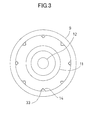
FIG.3 is a front view which shows a nozzle main body of a burner according to a second embodiment. -
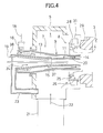
FIG.4 is a schematic sectional elevational view which shows a burner according to a third embodiment of the present invention. -
FIG.5 is a schematic sectional elevational view which shows a burner according to a fourth embodiment. - A description will be given below on an embodiment of the present invention by referring to the attached drawings.
- First, in
FIG. 1 , a description will be given on aburner 1 according to a first embodiment of the present invention. - In
FIG. 1 ,reference numeral 2 denotes a furnace andreference numeral 3 denotes a furnace wall of thefurnace 2. A throat 4 is provided on thefurnace wall 3, awind box 5 is provided on thefurnace wall 3 on an opposite side of afurnace 2, and theburner 1 is provided inside thewind box 5 concentrically with the throat 4. - The
burner 1 comprises a nozzlemain body 7 and asecondary air regulator 8 provided so as to surround a tip portion (an end portion of the furnace inner side) of the nozzlemain body 7. - The nozzle
main body 7 comprises anouter nozzle 9 and aninner nozzle 11 which are concentrically provided, and anoil burner 12 arranged on a center line of theinner nozzle 11, and each of theouter nozzle 9 and theinner nozzle 11 has a diameter reducing structure where a diameter gradually decreases respectively. Further, each of the shape of the cross section of theouter nozzle 9 and theinner nozzle 11 is circular, and afuel guiding space 13 which is a hollow cylindrical space and which has an open end on thefurnace 2 side is formed between theouter nozzle 9 and theinner nozzle 11. - On an inner peripheral surface of the
outer nozzle 9,deflector angles 14 each having a triangular cross section are arranged as many as required in a circumferential direction at a predetermined angle pitch, e.g., at intervals of 45°, and aconcentration adjustment ring 15 that surrounds theinner nozzle 11 is provided on theinner nozzle 11. - A pulverized coal
flow supply pipe 16 and an oxygen-containinggas supply pipe 17 is communicated with a base (an end on the opposite side of the furnace 2) of theouter nozzle 9 respectively from a tangential direction to theouter nozzle 9. The pulverized coalflow supply pipe 16 is connected with a pulverized coal mill (not shown), and a pulverized coal mixedflow 18, in which a carrier medium (referred to as a primary air hereinafter) is mixed with the pulverized coal, flows into thefuel guiding space 13 via the pulverized coalflow supply pipe 16 from a tangential direction. - It is to be noted that the oxygen concentration of the primary air in the pulverized coal mixed
flow 18 is lowered to, e.g., approximately 3% to 5% since the recirculated flue gas of the pulverized coal combusted in thefurnace 2 is mixed with the air having the oxygen concentration of 21% or the recirculated flue gas is used as it is, and even if the pulverized coal mixedflow 18 has a high temperature in a carrying process from pulverizing by the pulverized coal mill to flowing in of thefuel guiding space 13, it is configured so that a pulverized coal does not ignite. - Further, the oxygen-containing
gas supply pipe 17 is connected to an oxygen-containing gas supply source (not shown), and an oxygen-containinggas 19 such as pure oxygen or a mixed gas of oxygen and carbon dioxide or the like flows into thefuel guiding space 13 from the tangential direction via the oxygen-containinggas supply pipe 17. - The pulverized coal mixed
flow 18 and the oxygen-containinggas 19, which flow into thefuel guiding space 13, are mixed while swirling inside thefuel guiding space 13, and are spurted out, as an oxygen-containing pulverizedcoal flow 20 with a predetermined oxygen concentration, e.g., an oxygen concentration of 16% to 21%, from a tip of thefuel guiding space 13. - The oxygen-containing
gas supply pipe 17 communicates with the base of theouter nozzle 9 from an axial direction. It is arranged so that the oxygen-containinggas 19 may flow into thefuel guiding space 13 from the axial direction via the oxygen-containinggas supply pipe 17. - Further, a secondary
air flow duct 21 communicates with thewind box 5 and asecondary air 22 flows in as a combustion air via the secondaryair flow duct 21. As thesecondary air 22, a mixed gas obtained by mixing an oxygen with a recirculated flue gas provided when the pulverized coal is combusted in thefurnace 2, e. g. , a mixed gas containing approximately 30% oxygen and approximately 70% carbon dioxide, is used. - Further, a tertiary
air intake pipe 23, as an auxiliary combustion air intake pipe which is opened inside thewind box 5, communicates with a base of theinner nozzle 11, and thesecondary air 22 supplied to thewind box 5 is taken in and is introduced into theinner nozzle 11 as a combustion auxiliary air, i.e., atertiary air 24. - The
secondary air regulator 8 is constituted of an auxiliaryair regulating mechanism 25 which accommodates a tip portion of the nozzlemain body 7 and a mainair regulating mechanism 26 provided on an outer side of the auxiliaryair regulating mechanism 25 in a multiple concentric manner. - The auxiliary
air regulating mechanism 25 has a firstair guide duct 27 of which a diameter is gradually decreased toward a tip and manyinner air vanes 28 provided rotatably. Theinner air vanes 28 can synchronously turn via a link mechanism (not shown) and change an inclination angle with respect to the air flow. Further, the mainair regulating mechanism 26 has a secondair guide duct 29 of which its diameter is gradually decreased toward a tip and has manyouter air vanes 31 provided rotatably at equal intervals on the circumference, and theouter air vanes 31 can synchronously turn via a link mechanism (not shown) in the same way as the inner air vanes 28, and change an inclination angle with respect to the air flow. - The tip of the second
air guide duct 29 is continuous with the throat 4, the tip of the firstair guide duct 27 is placed at a position retreated from an inner wall surface of thefurnace wall 3, and tips of theouter nozzle 9 and theinner nozzle 11 are also placed at positions retreated from the inner wall surface of thefurnace wall 3. - Next, description will be given below on the combustion in the
burner 1. - The pulverized coal pulverized by a pulverized mill (not shown) is carried by a primary air and supplied to a base of the
fuel guiding space 13 as the pulverized coal mixedflow 18 via the pulverizedcoal supply pipe 16, and the oxygen-containinggas 19 is supplied from an oxygen-containing gas supply source (not shown) to the base of thefuel guiding space 13 through the oxygen-containinggas supply pipe 17. - The pulverized coal mixed
flow 18 and the oxygen-containinggas 19 supplied to the base of thefuel guiding space 13 flow toward thefurnace 2 while swirling in thefuel guiding space 13. The pulverized coal mixedflow 18 and the oxygen-containinggas 19 are mixed during a process of swirling in thefuel guiding space 13 and become the oxygen-containing pulverizedcoal flow 20 with increased oxygen concentration, and the pulverized coal concentration and the oxygen concentration in the oxygen-containing pulverizedcoal flow 20 are uniformed by the swirling. - Further, the oxygen-containing pulverized
coal flow 20 is reduced in size, accelerated, and rectified during a process of passing through theouter nozzle 9. At this time, by theconcentration adjustment ring 15, the oxygen-containing pulverizedcoal flow 20 is deflected and the pulverized coal concentration is adjusted, and further, by thedeflector angles 14, the pulverized coal in the oxygen-containing pulverizedcoal flow 20 is further uniformed and the swirling is suppressed, a speed in the axial direction is provided, and the oxygen-containing pulverizedcoal flow 20 is spurted out from the tip of theouter nozzle 9. - The oxygen-containing pulverized
coal flow 20 is subjected to the temperature rise by thesecondary air 22 while being spurted out to thefurnace 2 and is further heated up by receiving a radiation heat from inside of thefurnace 2. By the heating, volatile component is discharged from the pulverized coal, the volatile component is ignited and a flame is continuously maintained. - The
secondary air 22, that is a combustion air, is risen to a predetermined temperature and is supplied to thewind box 5. Thesecondary air 22 is swirled by theouter air vane 31 and spurted out into thefurnace 2 together with the oxygen-containing pulverizedcoal flow 20 through the secondaryair guide duct 29. - It is to be noted that a part of the
secondary air 22 taken into the secondaryair guide duct 29 is taken into the firstair guide duct 27 through theinner air vanes 28 and spurted out as a secondary auxiliary air. Further, theinner air vanes 28 are inclined with respect to an air flow and it is so arranged that a swirl flow is given to the part of thesecondary air 22 thus taken in. - The air amount adjustment performed by the
outer air vanes 31 and the intensity adjustment and the air amount adjustment of the swirl flow performed by theinner air vanes 28 change a supply amount and a flow state of thesecondary air 22, and a combustion state of the pulverized coal is adjusted. - Further, the part of the
secondary air 22 is guided as thetertiary air 24 to theinner nozzle 11 via the tertiaryair intake pipe 23 and spurted out from theinner nozzle 11. By thetertiary air 24 being spurted out, the combustion state of the pulverized coal is adjusted. Therefore, the adjustment is carried out so that the combustion state of the pulverized coal becomes the best suitable state by the adjustment of thesecondary air 22 and the adjustment of thetertiary air 24, etc. - As described above, in the first embodiment, since the oxygen-containing
gas 19 is supplied from the base of theouter nozzle 9 via the oxygen-containinggas supply pipe 17, the oxygen-containinggas 19 is mixed in the process that the pulverized coal mixedflow 18 flows in thefuel guiding space 13 and the oxygen-containing pulverizedcoal flow 20 having the oxygen concentration sufficient for ignition is provided, the oxygen concentration can be sufficiently increased at a stage where the oxygen-containing pulverizedcoal flow 20 is spurted out from theouter nozzle 9, and even if the oxygen concentration in the pulverized coal mixedflow 18 supplied to thefuel guiding space 13 is low, the ignition can be stabilized and the ignition can be promoted. - Further, since it is arranged so that the oxygen-containing
gas 19 is supplied from the base of theouter nozzle 9 and the oxygen-containing pulverizedcoal flow 20 having the oxygen concentration sufficient for the ignition flows only in thefuel guiding space 13, the pulverized coal mixedflow 18 pulverized by the pulverized coal mill (not shown) and supplied to thefuel guiding space 13 can become a low-oxygen state, a path where the oxygen-containing pulverizedcoal flow 20 flows can be shortened, the pulverized coal can be prevented from igniting and safety can be improved. - Further, since it is structured that the oxygen-containing
gas supply pipe 17 is connected to theouter nozzle 9 and is not extended to the inside of thefuel guiding space 13, the oxygen-containinggas supply pipe 17 is not exposed in thefuel guiding space 13, and it is possible to prevent the oxygen-containinggas supply pipe 17 from becoming worn due to the pulverized coal. - Further, since the
secondary air 22 of thewind box 5 is supplied to theinner nozzle 11 via the tertiaryair intake pipe 23, the combustion air can be supplied from the inner side and the outer side of theouter nozzle 9 from which the oxygen-containing pulverizedcoal flow 20 is spurted out, the mixing of the pulverized coal and oxygen can be promoted, and the stability of the ignition of the pulverized coal can be further enhanced. - Further, since the oxygen-containing
gas 19 is supplied into thefuel guiding space 13 via the oxygen-containinggas supply pipe 17, the recirculated flue gas when combusting the pulverized coal in thefurnace 2 is mixed with an air having the oxygen concentration of 21%, and a primary air is provided or since the recirculated flue gas is directly used as the primary air, the ratio of carbon dioxide in the air used for the combustion of the pulverized coal in thefurnace 2 becomes high, almost all of the flue gas after the combustion becomes carbon dioxide and capturing of the carbon dioxide can be easily carried out in a process after the combustion. - Next, referring to
FIG.2 andFIG.3 , description will be given on a second embodiment according to the present invention. It is to be noted that, inFIG.2 andFIG.3 , the same component as shown inFIG. 1 is referred by the same symbol, and detailed description is omitted. - In a
burner 1 according to the second embodiment, an oxygen-containinggas intake pipe 33 which forms a flow path of an oxygen-containinggas 19 is inserted inside eachdeflector angle 14, aring pipe 34 which is put over eachdeflector angle 14 is connected to a base end of thedeflector angle 14, and each oxygen-containinggas intake pipe 33 and thering pipe 34 communicate with each other. - Further, an oxygen-containing
gas supply pipe 35 penetrating anouter nozzle 9 is connected to thering pipe 34, the oxygen-containinggas supply pipe 35 is connected to an oxygen-containing gas supply source (not shown), and the oxygen-containinggas 19 such as pure oxygen or a mixed gas of oxygen and carbon dioxide, or the like, is supplied to thering pipe 34 from the oxygen-containing gas supply source via the oxygen-containinggas supply pipe 35. - In the second embodiment, the pulverized coal pulverized by a pulverized coal mill (not shown) is supplied into a
fuel guiding space 13 together with the primary air via a pulverized coalflow supply pipe 16 as a pulverized coal mixedflow 18, and the oxygen-containinggas 19 is supplied to thering pipe 34 via the oxygen-containinggas supply pipe 35. - The pulverized coal mixed
flow 18 supplied into thefuel guiding space 13 from a tangential direction is uniformed during a process of swirling in thefuel guiding space 13, reduced in size, accelerated, and rectified during a process of passing through anouter nozzle 9. Further, the pulverized coal concentration in the pulverized coal mixedflow 18 is adjusted by aconcentration adjustment ring 15. By the deflector angles 14, the pulverized coal in the pulverized coal mixedflow 18 is further uniformed, the swirling is suppressed and a speed in an axial direction is given, and the pulverized coal mixedflow 18 is spurted out from a tip of theouter nozzle 9. - Further, the oxygen-containing
gas 19 supplied to thering pipe 34 flows through the inside of thering pipe 34, is introduced into each oxygen-containinggas intake pipe 33, and is spurted out from the tips of each oxygen-containinggas intake pipe 33, i.e., the tips of eachdeflector angle 14. - Therefore, in the second embodiment, since it is structured so that the oxygen-containing
gas 19 is supplied to the pulverized coal mixedflow 18 from the tip of eachdeflector angle 14, the oxygen-containinggas 19 and the pulverized coal mixedflow 18 can be easily mixed, and even if the oxygen concentration in the pulverized coal mixedflow 18 is low, the ignition of the pulverized coal can be stabilized and the ignition can be promoted. - Further, similarly to the first embodiment, since a
secondary air 22 is supplied to theinner nozzle 11 via a tertiaryair intake pipe 23, the combustion air can be supplied from an inner side and an outer side of the pulverized coal mixedflow 18 spurted out from theouter nozzle 9, the mixing of the pulverized coal and oxygen can be promoted, and the stability of the ignition of the pulverized coal can be further enhanced. - Further, since the oxygen-containing
gas supply pipe 35 passes through theouter nozzle 9 and is connected to thering pipe 34, the oxygen-containinggas supply tube 35 is not exposed in thefuel guiding space 13, and it is possible to prevent the oxygen-containinggas supply pipe 35 from becoming worn due to the pulverized coal. - It is to be noted that, in the second embodiment, the oxygen-containing
gas intake pipes 33 are inserted in the deflector angles 14 and the oxygen-containinggas intake pipes 33 serve as the flow path of the oxygen-containinggas 19, but each of the deflector angles 14 may be a hollow structure and the deflector angles 14 themselves may serve as the flow path of the oxygen-containinggas 19. - Next, referring to
FIG.4 , description will be given on a third embodiment according to the present invention. It is to be noted that, inFIG. 4 , the same component as shown inFIG. 1 is referred by the same symbol, and detailed description is omitted. - In the third embodiment, a
concentration adjustment ring 15 has a hollow structure, and a plurality of oxygen-containing gas spurt outholes 37 are formed at a tip surface of theconcentration adjustment ring 15 at an equal angle pitch. - Further, the
concentration adjustment ring 15 is inserted in aninner nozzle 11 and connected with an oxygen-containinggas supply pipe 38 penetrating a peripheral wall of theinner nozzle 11. - The oxygen-containing
gas supply pipe 38 is connected to an oxygen-containing gas supply source, not shown, and an oxygen-containinggas 19 such as pure oxygen or a mixed gas of oxygen and carbon dioxide is supplied into theconcentration adjustment ring 15 via the oxygen-containinggas supply pipe 38 and spurted out into thefuel guiding space 13 from the oxygen-containing gas spurt out holes 37. - In the third embodiment, by supplying the oxygen-containing
gas 19 to a pulverized coal mixedflow 18 supplied via a pulverizedcoal supply pipe 16 via theconcentration adjustment ring 15, the pulverized coal mixedflow 18 and the oxygen-containinggas 19 is mixed and an oxygen-containing pulverizedcoal flow 20 having the oxygen concentration sufficient to ignite the pulverized coal can be provided at a stage of spurting out from a tip of theouter nozzle 9. - Therefore, even in a case where the oxygen concentration in the pulverized coal mixed
flow 18 supplied to thefuel guiding space 13 is low, the ignition of the pulverized coal can be stabilized and the ignition can be promoted. - Further, by supplying the oxygen-containing
gas 19 from theconcentration adjustment ring 15, a path where the oxygen-containing pulverizedcoal flow 20 runs can be further shortened. As a result, an ignition of the pulverized coal can be avoided and safety can be improved. - Additionally, since the oxygen-containing
gas supply pipe 38 is inserted in theinner nozzle 11, penetrates the peripheral wall of theinner nozzle 11 and is connected to theconcentration adjustment ring 15, the oxygen-containinggas supply pipe 38 is not exposed in thefuel guiding space 13 and the wear of the oxygen-containinggas supply pipe 38 due to the pulverized coal can be avoided. - A
burner 1 according to the third embodiment may further comprise the configuration of the second embodiment, i.e., an oxygen-containing gas intake pipe 33 (seeFIG.3 ) inserted in the deflector angles 14, the ring pipe 34 (seeFIG. 2 ) connected across the base ends of the deflector angles 14 and the oxygen-containing gas supply pipe 35 (seeFIG.2 ) which penetrates the peripheral wall of theouter nozzle 9 and is connected to thering pipe 34. - Next, referring to
FIG.5 , description will be given on a fourth embodiment according to the present invention. It is to be noted that, inFIG. 5 , the same components as shown inFIG. 1 is referred by the same symbol, and detailed description is omitted. - In a
burner 1 according to the fourth embodiment, a hollow firstconcentration adjustment ring 41 which surrounds aninner nozzle 11 is provided in afuel guiding space 13. The firstconcentration adjustment ring 41 has a base and a tip portion formed into tapered shapes respectively and a sectional side surface is in form of a trapezoidal shape. A plurality of first oxygen-containing gas spurt outholes 42 are formed at an equal angle pitch in an inclined surface of the firstconcentration adjustment ring 41 on the tip side. - Further, a first oxygen-containing
gas supply pipe 43 is connected to the firstconcentration adjustment ring 41. The first oxygen-containinggas supply pipe 43 is inserted in theinner nozzle 11 and penetrates a peripheral wall of theinner nozzle 11 so that the first oxygen-containingsupply pipe 43 is not exposed in thefuel guiding space 13. - The first oxygen-containing
gas supply pipe 43 is connected with an oxygen-containing gas supply source (not shown), and an oxygen-containinggas 19 such as pure oxygen or a mixed gas of oxygen and carbon dioxide, or the like, is supplied into the firstconcentration adjustment ring 41 via the first oxygen-containinggas supply pipe 43 and spurted out into thefuel guiding space 13 through the first oxygen-containing gas spurt out holes 42. - Further, a hollow second
concentration adjustment ring 44 is provided on an inner peripheral surface of anouter nozzle 9 on a base side than the firstconcentration adjustment ring 41 over the entire circumference. The secondconcentration adjustment ring 44 has a base and a tip portion formed into tapered shapes respectively and a sectional side surface is in form of a trapezoidal shape. A plurality of second oxygen-containing gas spurt outholes 45 are formed at an equal angle pitch in an inclined surface of the secondconcentration adjustment ring 44 on the tip side. - A second oxygen-containing
gas supply pipe 46 penetrating a peripheral wall of theouter nozzle 9 is connected to the secondconcentration adjustment ring 44 so that the second oxygen-containinggas supply pipe 46 is not exposed in thefuel guiding space 13. - The second oxygen-containing
gas supply pipe 46 is connected to an oxygen-containing gas supply source (not shown), and the oxygen-containinggas 19 is supplied into the secondconcentration adjustment ring 44 via the second oxygen-containinggas supply pipe 46 and spurted out into thefuel guiding space 13 through the second oxygen-containing gas spurt out holes 45. - In the fourth embodiment, by supplying the oxygen-containing
gas 19 to a pulverized coal mixedflow 18, which has been supplied via a pulverized coalflow supply pipe 16, via the firstconcentration adjustment ring 41 and the secondconcentration adjustment ring 44, the pulverized coal mixedflow 18 and the oxygen-containinggas 19 is mixed and an oxygen-containing pulverizedcoal flow 20 having the oxygen concentration sufficient to ignite the pulverized coal can be provided at a stage of the spurt out from a tip of theouter nozzle 9. - Therefore, even in a case where the oxygen concentration in the pulverized coal mixed
flow 18 supplied into thefuel guiding space 13 is low, the oxygen sufficient to combust the pulverized coal can be obtained, the ignition of the pulverized coal can be stabilized and the ignition can be promoted. - Further, the concentration of the pulverized coal in the oxygen-containing pulverized
coal flow 20 can be uniformed by the firstconcentration adjustment ring 41 and the secondconcentration adjustment ring 44 and a generated flame can be stabilized. - Additionally, since the first oxygen-containing
gas supply pipe 43 and the second oxygen-containinggas supply pipe 46 are not exposed in thefuel guiding space 13 respectively, the wear of the first oxygen-containinggas supply pipe 43 and the second oxygen-containinggas supply pipe 46 due to the pulverized coal can be avoided. - It is to be noted that, in the fourth embodiment, the oxygen-containing
gas supply pipes concentration adjustment ring 41 and the secondconcentration adjustment ring 44 and the oxygen-containinggas 19 is spurted out via the oxygen-containing gas spurt outholes gas 19 may be spurted out from either one of the firstconcentration adjustment ring 41 or the secondconcentration adjustment ring 44. - By the fact that an oxygen-containing gas can be supplied into a pulverized coal mixed flow having a low oxygen concentration, the oxygen concentration in the pulverized coal mixed flow can be raised and the ignition can be stabilized. And by supplying the oxygen-containing gas into the pulverized coal mixed flow which has been supplied into an outer nozzle, a path where the pulverized coal mixed flow runs is shortened, which can be applied to an improvement of safety.
-
- 1
- Burner
- 2
- Furnace
- 3
- Furnace wall
- 4
- Throat
- 5
- Wind box
- 7
- Nozzle main body
- 8
- Secondary air regulator
- 9
- Outer nozzle
- 11
- Inner nozzle
- 13
- Fuel guiding space
- 14
- Deflector angle
- 15
- Concentration adjustment ring
- 16
- Pulverized coal flow supply pipe
- 17
- Oxygen-containing gas supply pipe
- 18
- Pulverized coal mixed flow
- 19
- Oxygen-containing gas
- 20
- Oxygen-containing pulverized coal flow
- 22
- Secondary air (combustion air)
- 23
- Tertiary air intake pipe (auxiliary combustion air intake pipe)
- 24
- Tertiary air (auxiliary combustion air)
- 33
- Oxygen-containing gas intake pipe
- 34
- Ring pipe
- 35
- Oxygen-containing gas supply pipe
- 37
- Oxygen-containing gas spurt out hole
- 38
- Oxygen-containing gas supply pipe
- 41
- First concentration adjustment ring
- 42
- First oxygen-containing gas spurt out hole
- 43
- First oxygen-containing gas supply pipe
- 44
- Second concentration adjustment ring
- 45
- Second oxygen-containing gas spurt out hole
- 46
- Second oxygen-containing gas supply pipe
Claims (5)
- A burner comprising, a nozzle main body (7) which is installed along a central axis of a throat (4) provided on a furnace wall (3) and comprises an inner nozzle (11) in which an auxiliary combustion air (24) flows and an outer nozzle (9) which is provided on an outer side and concentrically with said inner nozzle and in which a pulverized coal mixed flow (18) obtained by mixing a carrying medium with a pulverized coal flow, a wind box (5) for accommodating said nozzle main body, a secondary air regulator (8) accommodated in said wind box and provided at a tip portion of said nozzle main body, an auxiliary combustion air intake pipe (23) for introducing a combustion air as an auxiliary combustion air into said inner nozzle from said wind box, a pulverized coal flow supply pipe (16) for introducing a pulverized coal mixed flow into said outer nozzle, and an oxygen-containing gas supply pipe (17, 35, 38, 43, 46) for supplying an oxygen-containing gas (19) to said pulverized coal mixed flow and raising the oxygen concentration in said pulverized coal mixed flow.
- A burner according to claim 1, further comprising two or more deflector angles (14) extending on an inner peripheral surface of said outer nozzle (9) along an axial direction of said outer nozzle, wherein a flow path (33) of an oxygen-containing gas (19) is formed in each of said deflector angles, a ring pipe (34) communicating with said flow path is connected across base ends of said deflector angles and said oxygen-containing gas supply pipe (35) penetrating a peripheral wall of said outer nozzle is connected to said ring pipe.
- A burner according to claim 1, wherein said oxygen-containing gas supply pipe (17) communicates with a base of said outer nozzle (9), and said oxygen-containing gas (19) is supplied from the base of said outer nozzle.
- A burner according to claim 1 or claim 2, further comprising a hollow concentration adjustment ring (15, 41) for surrounding said inner nozzle (11), wherein two or more holes (42) for spurting out oxygen-containing injection gas are provided at a tip surface of said concentration adjustment ring, and said oxygen-containing gas supply pipe (43) as inserted in said inner nozzle and for penetrating a peripheral wall of said inner nozzle is connected to said concentration adjustment ring.
- A burner according to claim 1 or claim 2, further comprising a first concentration adjustment ring (41) for surrounding said inner nozzle (11) and a second concentration adjustment ring (44) provided on an inner peripheral surface of said outer nozzle (9) over an entire circumference on a base side than said first concentration adjustment ring, wherein at least one concentration adjustment ring (41, 44) of said first concentration adjustment ring and said second concentration adjustment ring is hollow and has two or more holes (42, 45) for spurting out oxygen-containing gas provided at a tip surface, and said oxygen-containing gas supply pipe (43, 46) is connected to said one concentration adjustment ring (41, 44).
Applications Claiming Priority (2)
| Application Number | Priority Date | Filing Date | Title |
|---|---|---|---|
| JP2012148471A JP6011073B2 (en) | 2012-07-02 | 2012-07-02 | Burner |
| PCT/JP2013/062736 WO2014006969A1 (en) | 2012-07-02 | 2013-04-24 | Burner |
Publications (3)
| Publication Number | Publication Date |
|---|---|
| EP2868969A1 true EP2868969A1 (en) | 2015-05-06 |
| EP2868969A4 EP2868969A4 (en) | 2016-03-09 |
| EP2868969B1 EP2868969B1 (en) | 2019-01-30 |
Family
ID=49881731
Family Applications (1)
| Application Number | Title | Priority Date | Filing Date |
|---|---|---|---|
| EP13813164.4A Active EP2868969B1 (en) | 2012-07-02 | 2013-04-24 | Burner |
Country Status (5)
| Country | Link |
|---|---|
| US (1) | US9822968B2 (en) |
| EP (1) | EP2868969B1 (en) |
| JP (1) | JP6011073B2 (en) |
| AU (1) | AU2013284799B2 (en) |
| WO (1) | WO2014006969A1 (en) |
Cited By (3)
| Publication number | Priority date | Publication date | Assignee | Title |
|---|---|---|---|---|
| CN105114954A (en) * | 2015-09-24 | 2015-12-02 | 陈维汉 | Combustion device for multi-fuel premix swirl-flow combustion |
| CN105737152A (en) * | 2016-03-10 | 2016-07-06 | 陈维汉 | Combusting device for low nitrogen combustion of classification pre-mixed swirling flow |
| CN110360544A (en) * | 2019-08-09 | 2019-10-22 | 郑州釜鼎热能技术有限公司 | A kind of low nitrogen combustion apparatus of coal dust gasification and Staged Premixed Combustion |
Families Citing this family (24)
| Publication number | Priority date | Publication date | Assignee | Title |
|---|---|---|---|---|
| CN103868068B (en) * | 2014-03-24 | 2016-03-02 | 王龙陵 | A kind of high-temperature oxygen direct-fire and surely fire system |
| JP6326918B2 (en) * | 2014-04-02 | 2018-05-23 | 株式会社Ihi | Pulverized coal burner |
| US10526953B2 (en) | 2017-03-30 | 2020-01-07 | Quest Engines, LLC | Internal combustion engine |
| US10989138B2 (en) | 2017-03-30 | 2021-04-27 | Quest Engines, LLC | Internal combustion engine |
| US10598285B2 (en) | 2017-03-30 | 2020-03-24 | Quest Engines, LLC | Piston sealing system |
| US10590834B2 (en) | 2017-03-30 | 2020-03-17 | Quest Engines, LLC | Internal combustion engine |
| US10590813B2 (en) | 2017-03-30 | 2020-03-17 | Quest Engines, LLC | Internal combustion engine |
| US10753308B2 (en) | 2017-03-30 | 2020-08-25 | Quest Engines, LLC | Internal combustion engine |
| US11041456B2 (en) | 2017-03-30 | 2021-06-22 | Quest Engines, LLC | Internal combustion engine |
| US10465629B2 (en) | 2017-03-30 | 2019-11-05 | Quest Engines, LLC | Internal combustion engine having piston with deflector channels and complementary cylinder head |
| WO2018201045A1 (en) | 2017-04-28 | 2018-11-01 | Quest Engines, LLC | A variable volume chamber device |
| WO2018204684A1 (en) | 2017-05-04 | 2018-11-08 | Quest Engines, LLC | Variable volume chamber for interaction with a fluid |
| JP6863189B2 (en) * | 2017-09-05 | 2021-04-21 | トヨタ自動車株式会社 | Nozzle structure for hydrogen gas burner equipment |
| US10808866B2 (en) | 2017-09-29 | 2020-10-20 | Quest Engines, LLC | Apparatus and methods for controlling the movement of matter |
| CN107940498A (en) * | 2017-12-20 | 2018-04-20 | 国丰新能源江苏有限公司 | The auxiliary combustion device combined with secondary air channel |
| CN108061301A (en) * | 2018-01-23 | 2018-05-22 | 上海云汇环保科技有限公司 | A kind of novel steel ladle baking burner |
| WO2019147797A2 (en) | 2018-01-26 | 2019-08-01 | Quest Engines, LLC | Audio source waveguide |
| US10753267B2 (en) | 2018-01-26 | 2020-08-25 | Quest Engines, LLC | Method and apparatus for producing stratified streams |
| CN109945189B (en) * | 2019-03-20 | 2023-09-05 | 中国矿业大学 | A low-concentration gas pulsating burner with improved main pipe |
| JP7429501B2 (en) * | 2019-04-10 | 2024-02-08 | 株式会社Ihi | powder injection device |
| CN110595060A (en) * | 2019-10-10 | 2019-12-20 | 襄阳中和机电技术有限公司 | A pipeline type oil-coal mixed combustion combustion system |
| US10845052B1 (en) * | 2019-12-20 | 2020-11-24 | Jupiter Oxygen Corporation | Combustion system comprising an annular shroud burner |
| CN112178633A (en) * | 2020-09-29 | 2021-01-05 | 湖北赤焰热能工程有限公司 | Concentrated double-air-regulation cyclone burner and method |
| CN114017795B (en) * | 2021-11-26 | 2025-07-11 | 烟台龙源电力技术股份有限公司 | Pulverized coal ignition device |
Family Cites Families (17)
| Publication number | Priority date | Publication date | Assignee | Title |
|---|---|---|---|---|
| JPS63142095A (en) * | 1986-12-05 | 1988-06-14 | Babcock Hitachi Kk | Jet-layer coal gasification furnace |
| JPH07293823A (en) * | 1994-04-27 | 1995-11-10 | Ishikawajima Harima Heavy Ind Co Ltd | Pulverized coal burner |
| JPH08110014A (en) * | 1994-10-07 | 1996-04-30 | Babcock Hitachi Kk | Fine powder coal combustor |
| JPH09178116A (en) * | 1995-12-22 | 1997-07-11 | Central Res Inst Of Electric Power Ind | Pulverized coal burner |
| JPH1038216A (en) * | 1996-07-22 | 1998-02-13 | Ishikawajima Harima Heavy Ind Co Ltd | Pulverized coal burner |
| JP3349380B2 (en) * | 1997-01-17 | 2002-11-25 | 三菱重工業株式会社 | Burner for wet furnace |
| JP4460680B2 (en) * | 1999-07-13 | 2010-05-12 | 三菱重工業株式会社 | Coal gasifier |
| AU776725B2 (en) | 2000-08-04 | 2004-09-16 | Mitsubishi Hitachi Power Systems, Ltd. | Solid fuel burner and combustion method using solid fuel burner |
| JP2002340306A (en) * | 2001-05-17 | 2002-11-27 | Babcock Hitachi Kk | Burner for burning solid fuel and combustion device equipped therewith |
| JP4150968B2 (en) | 2003-11-10 | 2008-09-17 | 株式会社日立製作所 | Solid fuel burner and combustion method of solid fuel burner |
| JP4998001B2 (en) * | 2007-02-09 | 2012-08-15 | 株式会社Ihi | Pulverized coal burner |
| JP2009079794A (en) * | 2007-09-25 | 2009-04-16 | Babcock Hitachi Kk | Solid fuel burner, combustion device using the same, and its operation method |
| SE532338C2 (en) * | 2008-04-22 | 2009-12-15 | Aga Ab | Method and apparatus for combustion of solid phase fuel |
| JP2009264654A (en) | 2008-04-24 | 2009-11-12 | Babcock Hitachi Kk | Pulverized coal burner |
| JP4896194B2 (en) | 2009-09-30 | 2012-03-14 | 株式会社日立製作所 | Oxyfuel boiler plant |
| JP2011106726A (en) * | 2009-11-17 | 2011-06-02 | Ihi Corp | Pulverized coal burner |
| JP5566317B2 (en) * | 2011-02-18 | 2014-08-06 | バブコック日立株式会社 | Solid fuel burner |
-
2012
- 2012-07-02 JP JP2012148471A patent/JP6011073B2/en active Active
-
2013
- 2013-04-24 WO PCT/JP2013/062736 patent/WO2014006969A1/en not_active Ceased
- 2013-04-24 AU AU2013284799A patent/AU2013284799B2/en active Active
- 2013-04-24 EP EP13813164.4A patent/EP2868969B1/en active Active
- 2013-04-24 US US14/411,729 patent/US9822968B2/en active Active
Cited By (3)
| Publication number | Priority date | Publication date | Assignee | Title |
|---|---|---|---|---|
| CN105114954A (en) * | 2015-09-24 | 2015-12-02 | 陈维汉 | Combustion device for multi-fuel premix swirl-flow combustion |
| CN105737152A (en) * | 2016-03-10 | 2016-07-06 | 陈维汉 | Combusting device for low nitrogen combustion of classification pre-mixed swirling flow |
| CN110360544A (en) * | 2019-08-09 | 2019-10-22 | 郑州釜鼎热能技术有限公司 | A kind of low nitrogen combustion apparatus of coal dust gasification and Staged Premixed Combustion |
Also Published As
| Publication number | Publication date |
|---|---|
| US20150176840A1 (en) | 2015-06-25 |
| WO2014006969A1 (en) | 2014-01-09 |
| AU2013284799B2 (en) | 2016-01-14 |
| AU2013284799A1 (en) | 2015-02-05 |
| EP2868969A4 (en) | 2016-03-09 |
| JP2014009922A (en) | 2014-01-20 |
| JP6011073B2 (en) | 2016-10-19 |
| US9822968B2 (en) | 2017-11-21 |
| EP2868969B1 (en) | 2019-01-30 |
Similar Documents
| Publication | Publication Date | Title |
|---|---|---|
| EP2868969B1 (en) | Burner | |
| EP2479491B1 (en) | Method and burner for burning lean gas in a power plant boiler | |
| EP1936270A2 (en) | Pulverized solid fuel burner | |
| JP6906881B1 (en) | Low flammability fuel combustion device | |
| CN113915613B (en) | Method and burner head for the staged combustion of fuel | |
| KR102509551B1 (en) | Low NOx Burner | |
| CN214581067U (en) | Glow burner | |
| US7430970B2 (en) | Burner with center air jet | |
| JP2014102043A (en) | Biomass burner | |
| US12196415B2 (en) | Radiant wall burner | |
| EP2267368A1 (en) | Oxygen combustion boiler and pulverized coal burner | |
| CN113028398B (en) | Glow flame generating method of glow flame burner and glow flame burner | |
| JP5245558B2 (en) | Burner for fine fuel | |
| WO2011030501A1 (en) | Pulverized coal boiler | |
| JP2014153015A (en) | Pulverized coal burner | |
| EP4253838A1 (en) | Gas burner with low nox emission | |
| JP2014105892A (en) | Burner | |
| RU2480673C1 (en) | Device for fuel burning | |
| RU2433342C2 (en) | BURNER WITH CENTRAL AIR JET AND METHOD TO REDUCE NOx EMISSION OF SPECIFIED BURNER (VERSIONS) | |
| CN121752845A (en) | Burner, in particular for a direct flame preheating section of a continuous metal strip treatment line | |
| CN117989541A (en) | Low-nitrogen combustion head for sectional combustion | |
| JP2018204837A (en) | Combustor | |
| AU2006203560B2 (en) | Burner with center air jet | |
| CN116025902A (en) | Low nitrogen burner | |
| JP2017227351A (en) | Combustion-supporting gas burner and by-product gas burner |
Legal Events
| Date | Code | Title | Description |
|---|---|---|---|
| PUAI | Public reference made under article 153(3) epc to a published international application that has entered the european phase |
Free format text: ORIGINAL CODE: 0009012 |
|
| 17P | Request for examination filed |
Effective date: 20150129 |
|
| AK | Designated contracting states |
Kind code of ref document: A1 Designated state(s): AL AT BE BG CH CY CZ DE DK EE ES FI FR GB GR HR HU IE IS IT LI LT LU LV MC MK MT NL NO PL PT RO RS SE SI SK SM TR |
|
| AX | Request for extension of the european patent |
Extension state: BA ME |
|
| DAX | Request for extension of the european patent (deleted) | ||
| RIN1 | Information on inventor provided before grant (corrected) |
Inventor name: TAMURA, MASATO Inventor name: ITOKAZU, RYUNOSUKE |
|
| RA4 | Supplementary search report drawn up and despatched (corrected) |
Effective date: 20160209 |
|
| RIC1 | Information provided on ipc code assigned before grant |
Ipc: F23K 3/02 20060101ALI20160203BHEP Ipc: F23L 9/00 20060101ALI20160203BHEP Ipc: F23L 7/00 20060101AFI20160203BHEP Ipc: F23C 7/02 20060101ALI20160203BHEP Ipc: F23D 14/24 20060101ALI20160203BHEP Ipc: F23D 14/22 20060101ALI20160203BHEP |
|
| GRAP | Despatch of communication of intention to grant a patent |
Free format text: ORIGINAL CODE: EPIDOSNIGR1 |
|
| STAA | Information on the status of an ep patent application or granted ep patent |
Free format text: STATUS: GRANT OF PATENT IS INTENDED |
|
| INTG | Intention to grant announced |
Effective date: 20180824 |
|
| GRAS | Grant fee paid |
Free format text: ORIGINAL CODE: EPIDOSNIGR3 |
|
| GRAA | (expected) grant |
Free format text: ORIGINAL CODE: 0009210 |
|
| STAA | Information on the status of an ep patent application or granted ep patent |
Free format text: STATUS: THE PATENT HAS BEEN GRANTED |
|
| AK | Designated contracting states |
Kind code of ref document: B1 Designated state(s): AL AT BE BG CH CY CZ DE DK EE ES FI FR GB GR HR HU IE IS IT LI LT LU LV MC MK MT NL NO PL PT RO RS SE SI SK SM TR |
|
| REG | Reference to a national code |
Ref country code: GB Ref legal event code: FG4D |
|
| REG | Reference to a national code |
Ref country code: CH Ref legal event code: EP |
|
| REG | Reference to a national code |
Ref country code: AT Ref legal event code: REF Ref document number: 1093579 Country of ref document: AT Kind code of ref document: T Effective date: 20190215 |
|
| REG | Reference to a national code |
Ref country code: IE Ref legal event code: FG4D |
|
| REG | Reference to a national code |
Ref country code: DE Ref legal event code: R096 Ref document number: 602013050305 Country of ref document: DE |
|
| REG | Reference to a national code |
Ref country code: LT Ref legal event code: MG4D |
|
| REG | Reference to a national code |
Ref country code: NL Ref legal event code: MP Effective date: 20190130 |
|
| PG25 | Lapsed in a contracting state [announced via postgrant information from national office to epo] |
Ref country code: FI Free format text: LAPSE BECAUSE OF FAILURE TO SUBMIT A TRANSLATION OF THE DESCRIPTION OR TO PAY THE FEE WITHIN THE PRESCRIBED TIME-LIMIT Effective date: 20190130 Ref country code: NO Free format text: LAPSE BECAUSE OF FAILURE TO SUBMIT A TRANSLATION OF THE DESCRIPTION OR TO PAY THE FEE WITHIN THE PRESCRIBED TIME-LIMIT Effective date: 20190430 Ref country code: PT Free format text: LAPSE BECAUSE OF FAILURE TO SUBMIT A TRANSLATION OF THE DESCRIPTION OR TO PAY THE FEE WITHIN THE PRESCRIBED TIME-LIMIT Effective date: 20190530 Ref country code: PL Free format text: LAPSE BECAUSE OF FAILURE TO SUBMIT A TRANSLATION OF THE DESCRIPTION OR TO PAY THE FEE WITHIN THE PRESCRIBED TIME-LIMIT Effective date: 20190130 Ref country code: NL Free format text: LAPSE BECAUSE OF FAILURE TO SUBMIT A TRANSLATION OF THE DESCRIPTION OR TO PAY THE FEE WITHIN THE PRESCRIBED TIME-LIMIT Effective date: 20190130 Ref country code: SE Free format text: LAPSE BECAUSE OF FAILURE TO SUBMIT A TRANSLATION OF THE DESCRIPTION OR TO PAY THE FEE WITHIN THE PRESCRIBED TIME-LIMIT Effective date: 20190130 Ref country code: ES Free format text: LAPSE BECAUSE OF FAILURE TO SUBMIT A TRANSLATION OF THE DESCRIPTION OR TO PAY THE FEE WITHIN THE PRESCRIBED TIME-LIMIT Effective date: 20190130 Ref country code: LT Free format text: LAPSE BECAUSE OF FAILURE TO SUBMIT A TRANSLATION OF THE DESCRIPTION OR TO PAY THE FEE WITHIN THE PRESCRIBED TIME-LIMIT Effective date: 20190130 |
|
| REG | Reference to a national code |
Ref country code: AT Ref legal event code: MK05 Ref document number: 1093579 Country of ref document: AT Kind code of ref document: T Effective date: 20190130 |
|
| PG25 | Lapsed in a contracting state [announced via postgrant information from national office to epo] |
Ref country code: HR Free format text: LAPSE BECAUSE OF FAILURE TO SUBMIT A TRANSLATION OF THE DESCRIPTION OR TO PAY THE FEE WITHIN THE PRESCRIBED TIME-LIMIT Effective date: 20190130 Ref country code: RS Free format text: LAPSE BECAUSE OF FAILURE TO SUBMIT A TRANSLATION OF THE DESCRIPTION OR TO PAY THE FEE WITHIN THE PRESCRIBED TIME-LIMIT Effective date: 20190130 Ref country code: IS Free format text: LAPSE BECAUSE OF FAILURE TO SUBMIT A TRANSLATION OF THE DESCRIPTION OR TO PAY THE FEE WITHIN THE PRESCRIBED TIME-LIMIT Effective date: 20190530 Ref country code: BG Free format text: LAPSE BECAUSE OF FAILURE TO SUBMIT A TRANSLATION OF THE DESCRIPTION OR TO PAY THE FEE WITHIN THE PRESCRIBED TIME-LIMIT Effective date: 20190430 Ref country code: GR Free format text: LAPSE BECAUSE OF FAILURE TO SUBMIT A TRANSLATION OF THE DESCRIPTION OR TO PAY THE FEE WITHIN THE PRESCRIBED TIME-LIMIT Effective date: 20190501 Ref country code: LV Free format text: LAPSE BECAUSE OF FAILURE TO SUBMIT A TRANSLATION OF THE DESCRIPTION OR TO PAY THE FEE WITHIN THE PRESCRIBED TIME-LIMIT Effective date: 20190130 |
|
| PG25 | Lapsed in a contracting state [announced via postgrant information from national office to epo] |
Ref country code: EE Free format text: LAPSE BECAUSE OF FAILURE TO SUBMIT A TRANSLATION OF THE DESCRIPTION OR TO PAY THE FEE WITHIN THE PRESCRIBED TIME-LIMIT Effective date: 20190130 Ref country code: SK Free format text: LAPSE BECAUSE OF FAILURE TO SUBMIT A TRANSLATION OF THE DESCRIPTION OR TO PAY THE FEE WITHIN THE PRESCRIBED TIME-LIMIT Effective date: 20190130 Ref country code: IT Free format text: LAPSE BECAUSE OF FAILURE TO SUBMIT A TRANSLATION OF THE DESCRIPTION OR TO PAY THE FEE WITHIN THE PRESCRIBED TIME-LIMIT Effective date: 20190130 Ref country code: DK Free format text: LAPSE BECAUSE OF FAILURE TO SUBMIT A TRANSLATION OF THE DESCRIPTION OR TO PAY THE FEE WITHIN THE PRESCRIBED TIME-LIMIT Effective date: 20190130 Ref country code: AL Free format text: LAPSE BECAUSE OF FAILURE TO SUBMIT A TRANSLATION OF THE DESCRIPTION OR TO PAY THE FEE WITHIN THE PRESCRIBED TIME-LIMIT Effective date: 20190130 Ref country code: RO Free format text: LAPSE BECAUSE OF FAILURE TO SUBMIT A TRANSLATION OF THE DESCRIPTION OR TO PAY THE FEE WITHIN THE PRESCRIBED TIME-LIMIT Effective date: 20190130 Ref country code: CZ Free format text: LAPSE BECAUSE OF FAILURE TO SUBMIT A TRANSLATION OF THE DESCRIPTION OR TO PAY THE FEE WITHIN THE PRESCRIBED TIME-LIMIT Effective date: 20190130 |
|
| REG | Reference to a national code |
Ref country code: DE Ref legal event code: R097 Ref document number: 602013050305 Country of ref document: DE |
|
| PG25 | Lapsed in a contracting state [announced via postgrant information from national office to epo] |
Ref country code: SM Free format text: LAPSE BECAUSE OF FAILURE TO SUBMIT A TRANSLATION OF THE DESCRIPTION OR TO PAY THE FEE WITHIN THE PRESCRIBED TIME-LIMIT Effective date: 20190130 |
|
| REG | Reference to a national code |
Ref country code: CH Ref legal event code: PL |
|
| PLBE | No opposition filed within time limit |
Free format text: ORIGINAL CODE: 0009261 |
|
| STAA | Information on the status of an ep patent application or granted ep patent |
Free format text: STATUS: NO OPPOSITION FILED WITHIN TIME LIMIT |
|
| REG | Reference to a national code |
Ref country code: BE Ref legal event code: MM Effective date: 20190430 |
|
| GBPC | Gb: european patent ceased through non-payment of renewal fee |
Effective date: 20190430 |
|
| PG25 | Lapsed in a contracting state [announced via postgrant information from national office to epo] |
Ref country code: AT Free format text: LAPSE BECAUSE OF FAILURE TO SUBMIT A TRANSLATION OF THE DESCRIPTION OR TO PAY THE FEE WITHIN THE PRESCRIBED TIME-LIMIT Effective date: 20190130 Ref country code: MC Free format text: LAPSE BECAUSE OF FAILURE TO SUBMIT A TRANSLATION OF THE DESCRIPTION OR TO PAY THE FEE WITHIN THE PRESCRIBED TIME-LIMIT Effective date: 20190130 Ref country code: LU Free format text: LAPSE BECAUSE OF NON-PAYMENT OF DUE FEES Effective date: 20190424 |
|
| 26N | No opposition filed |
Effective date: 20191031 |
|
| PG25 | Lapsed in a contracting state [announced via postgrant information from national office to epo] |
Ref country code: GB Free format text: LAPSE BECAUSE OF NON-PAYMENT OF DUE FEES Effective date: 20190430 Ref country code: CH Free format text: LAPSE BECAUSE OF NON-PAYMENT OF DUE FEES Effective date: 20190430 Ref country code: LI Free format text: LAPSE BECAUSE OF NON-PAYMENT OF DUE FEES Effective date: 20190430 |
|
| PG25 | Lapsed in a contracting state [announced via postgrant information from national office to epo] |
Ref country code: FR Free format text: LAPSE BECAUSE OF NON-PAYMENT OF DUE FEES Effective date: 20190430 Ref country code: BE Free format text: LAPSE BECAUSE OF NON-PAYMENT OF DUE FEES Effective date: 20190430 Ref country code: SI Free format text: LAPSE BECAUSE OF FAILURE TO SUBMIT A TRANSLATION OF THE DESCRIPTION OR TO PAY THE FEE WITHIN THE PRESCRIBED TIME-LIMIT Effective date: 20190130 |
|
| PG25 | Lapsed in a contracting state [announced via postgrant information from national office to epo] |
Ref country code: TR Free format text: LAPSE BECAUSE OF FAILURE TO SUBMIT A TRANSLATION OF THE DESCRIPTION OR TO PAY THE FEE WITHIN THE PRESCRIBED TIME-LIMIT Effective date: 20190130 |
|
| PG25 | Lapsed in a contracting state [announced via postgrant information from national office to epo] |
Ref country code: IE Free format text: LAPSE BECAUSE OF NON-PAYMENT OF DUE FEES Effective date: 20190424 |
|
| PG25 | Lapsed in a contracting state [announced via postgrant information from national office to epo] |
Ref country code: CY Free format text: LAPSE BECAUSE OF FAILURE TO SUBMIT A TRANSLATION OF THE DESCRIPTION OR TO PAY THE FEE WITHIN THE PRESCRIBED TIME-LIMIT Effective date: 20190130 |
|
| PG25 | Lapsed in a contracting state [announced via postgrant information from national office to epo] |
Ref country code: MT Free format text: LAPSE BECAUSE OF FAILURE TO SUBMIT A TRANSLATION OF THE DESCRIPTION OR TO PAY THE FEE WITHIN THE PRESCRIBED TIME-LIMIT Effective date: 20190130 Ref country code: HU Free format text: LAPSE BECAUSE OF FAILURE TO SUBMIT A TRANSLATION OF THE DESCRIPTION OR TO PAY THE FEE WITHIN THE PRESCRIBED TIME-LIMIT; INVALID AB INITIO Effective date: 20130424 |
|
| PG25 | Lapsed in a contracting state [announced via postgrant information from national office to epo] |
Ref country code: MK Free format text: LAPSE BECAUSE OF FAILURE TO SUBMIT A TRANSLATION OF THE DESCRIPTION OR TO PAY THE FEE WITHIN THE PRESCRIBED TIME-LIMIT Effective date: 20190130 |
|
| PGFP | Annual fee paid to national office [announced via postgrant information from national office to epo] |
Ref country code: DE Payment date: 20250319 Year of fee payment: 13 |