EP2267368A1 - Oxygen combustion boiler and pulverized coal burner - Google Patents
Oxygen combustion boiler and pulverized coal burner Download PDFInfo
- Publication number
- EP2267368A1 EP2267368A1 EP08720362A EP08720362A EP2267368A1 EP 2267368 A1 EP2267368 A1 EP 2267368A1 EP 08720362 A EP08720362 A EP 08720362A EP 08720362 A EP08720362 A EP 08720362A EP 2267368 A1 EP2267368 A1 EP 2267368A1
- Authority
- EP
- European Patent Office
- Prior art keywords
- burner
- oxygen
- pulverized coal
- outer cylinder
- combustion boiler
- Prior art date
- Legal status (The legal status is an assumption and is not a legal conclusion. Google has not performed a legal analysis and makes no representation as to the accuracy of the status listed.)
- Granted
Links
Images

Classifications
-
- F—MECHANICAL ENGINEERING; LIGHTING; HEATING; WEAPONS; BLASTING
- F23—COMBUSTION APPARATUS; COMBUSTION PROCESSES
- F23D—BURNERS
- F23D1/00—Burners for combustion of pulverulent fuel
-
- F—MECHANICAL ENGINEERING; LIGHTING; HEATING; WEAPONS; BLASTING
- F23—COMBUSTION APPARATUS; COMBUSTION PROCESSES
- F23L—SUPPLYING AIR OR NON-COMBUSTIBLE LIQUIDS OR GASES TO COMBUSTION APPARATUS IN GENERAL ; VALVES OR DAMPERS SPECIALLY ADAPTED FOR CONTROLLING AIR SUPPLY OR DRAUGHT IN COMBUSTION APPARATUS; INDUCING DRAUGHT IN COMBUSTION APPARATUS; TOPS FOR CHIMNEYS OR VENTILATING SHAFTS; TERMINALS FOR FLUES
- F23L7/00—Supplying non-combustible liquids or gases, other than air, to the fire, e.g. oxygen, steam
- F23L7/007—Supplying oxygen or oxygen-enriched air
-
- F—MECHANICAL ENGINEERING; LIGHTING; HEATING; WEAPONS; BLASTING
- F23—COMBUSTION APPARATUS; COMBUSTION PROCESSES
- F23D—BURNERS
- F23D2201/00—Burners adapted for particulate solid or pulverulent fuels
- F23D2201/10—Nozzle tips
-
- F—MECHANICAL ENGINEERING; LIGHTING; HEATING; WEAPONS; BLASTING
- F23—COMBUSTION APPARATUS; COMBUSTION PROCESSES
- F23D—BURNERS
- F23D2900/00—Special features of, or arrangements for burners using fluid fuels or solid fuels suspended in a carrier gas
- F23D2900/00006—Liquid fuel burners using pure oxygen or O2-enriched air as oxidant
-
- F—MECHANICAL ENGINEERING; LIGHTING; HEATING; WEAPONS; BLASTING
- F23—COMBUSTION APPARATUS; COMBUSTION PROCESSES
- F23L—SUPPLYING AIR OR NON-COMBUSTIBLE LIQUIDS OR GASES TO COMBUSTION APPARATUS IN GENERAL ; VALVES OR DAMPERS SPECIALLY ADAPTED FOR CONTROLLING AIR SUPPLY OR DRAUGHT IN COMBUSTION APPARATUS; INDUCING DRAUGHT IN COMBUSTION APPARATUS; TOPS FOR CHIMNEYS OR VENTILATING SHAFTS; TERMINALS FOR FLUES
- F23L2900/00—Special arrangements for supplying or treating air or oxidant for combustion; Injecting inert gas, water or steam into the combustion chamber
- F23L2900/07005—Injecting pure oxygen or oxygen enriched air
-
- Y—GENERAL TAGGING OF NEW TECHNOLOGICAL DEVELOPMENTS; GENERAL TAGGING OF CROSS-SECTIONAL TECHNOLOGIES SPANNING OVER SEVERAL SECTIONS OF THE IPC; TECHNICAL SUBJECTS COVERED BY FORMER USPC CROSS-REFERENCE ART COLLECTIONS [XRACs] AND DIGESTS
- Y02—TECHNOLOGIES OR APPLICATIONS FOR MITIGATION OR ADAPTATION AGAINST CLIMATE CHANGE
- Y02E—REDUCTION OF GREENHOUSE GAS [GHG] EMISSIONS, RELATED TO ENERGY GENERATION, TRANSMISSION OR DISTRIBUTION
- Y02E20/00—Combustion technologies with mitigation potential
- Y02E20/34—Indirect CO2mitigation, i.e. by acting on non CO2directly related matters of the process, e.g. pre-heating or heat recovery
Definitions
- the present invention relates to a pulverized coal burner for an oxyfuel combustion burner.
- Such an oxyfuel combustion boiler comprises an oxygen introduction passage for introduction of oxygen to an air feed passage connected to a wind box on an inlet side of an oxyfuel combustion boiler body, and an exhaust gas circulation passage branched from an exhaust gas passage connected to an outlet side of the oxyfuel combustion boiler body for connection with the air feed passage.
- air is introduced through the air feed passage to the oxyfuel combustion boiler body for combustion of fuel.
- dampers, etc., disposed in the passages are switched to circulate an exhaust gas discharged from the oxyfuel combustion boiler body through the exhaust gas circulation passage to the oxyfuel combustion boiler body while oxygen is introduced through the oxygen introduction passage to the oxyfuel combustion boiler body to perform the oxyfuel combustion of the fuel while constraining reduction of oxygen concentration due to the circulation of the exhaust gas to thereby increase a concentration of carbon dioxide in the exhaust gas, the carbon dioxide being captured from a portion of the exhaust gas.
- the oxyfuel combustion boiler comprises a pulverized coal burner which is composed of an oil burner and a pulverized coal feed passage, and an oxygen injection nozzle which supplies the pulverized coal feed passage with oxygen to mix and burn pulverized coal, etc., with air from the wind box (e.g., Patent Literature 1).
- Patent Literatures 2 to 5 describe techniques related to such an oxyfuel combustion boiler.
- an oxyfuel combustion boiler is simply provided with a pulverized coal burner and an oxygen injection nozzle, etc.
- oxygen is unable to be fed properly so that, disadvantageously, the combustion from the pulverized coal burner becomes non-uniform and a tip of the oxygen injection nozzle and a tip of the pulverized coal burner reach abnormally high temperatures.
- the oxygen injection nozzle is disposed in the pulverized coal feed passage as described in the prior art literatures, oxygen is not sufficiently mixed with pulverized coal, resulting in failure of uniform combustion.
- the invention was made in view of the above and has its object to provide a pulverized coal burner for an oxyfuel combustion boiler which attains uniform combustion with a pulverized coal burner and which constrains a temperature rise of oxygen injection means.
- the invention is directed to a pulverized coal burner for an oxyfuel combustion boiler comprising burner inner and outer cylinders which pass through a wind box and come close to a throat portion, a pulverized coal feed passage provided between the burner inner and outer cylinders and a plurality of oxygen injection means outwardly of the burner outer cylinder for directly feeding oxygen ahead of the burner outer cylinder.
- each of the oxygen injection means is disposed at a position preventing a tip on the injection side from getting ahead of a tip of the burner outer cylinder and is configured to prevent injected oxygen from hitting a tip of the burner outer cylinder.
- the plurality of oxygen injection means are arranged circumferentially and equidistantly around a burner axis.
- each of the oxygen injection means comprises an oxygen injection nozzle for injection of oxygen and an oxygen feed passage which supplies oxygen to the oxygen injection nozzle through a system separated from air of the wind box.
- oxygen is directly fed to pulverized coal and/or flame outwardly of a burner outer cylinder which makes up a pulverized coal feed passage, so that excellent effects of making uniform combustion from the pulverized coal burner and constraining a temperature rise of oxygen injection means are achievable.
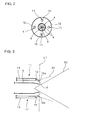
- FIGs. 1 to 3 show the embodiment of a pulverized coal burner for an oxyfuel combustion boiler of the invention.
- the pulverized coal burner for the oxyfuel combustion boiler of the embodiment comprises burner outer and inner cylinders 4 and 5 concentrically disposed to penetrate a wind box 2 attached to an oxyfuel combustion boiler 1 and to come closer to a throat portion 3 formed in a furnace wall (not shown) of the oxyfuel combustion boiler 1 and tip portions 6 of the burner outer and inner cylinders 4 and 5 are opened toward the throat portion 3.
- the burner inner cylinder 5 is axially provided with an oil burner 7.
- the oil burner 7 is fed with fuel such as oil from outside of the burner inner cylinder 5; introduced into the burner inner cylinder 5 is air of the wind box 2 via an introduction line 8.
- a pulverized coal feed passage 9 Formed between the burner inner and outer cylinders 5 and 4 is a pulverized coal feed passage 9 allowing distribution of pulverized coal.
- the burner outer cylinder 4 is provided with a pulverized coal introducing unit 10 located outside of the wind box 2.
- the pulverized coal introducing unit 10 is connected to a feed line (not shown) fed with pulverized coal from a mill (not shown), etc., and has a configuration of feeding pulverized coal to the pulverized coal feed passage 9.
- oxygen injection means 11 Disposed outwardly of the burner outer cylinder 4 are a plurality of (four in Fig. 2 ) oxygen injection means 11 which are circumferentially equidistantly arranged around the oil burner 7 to penetrate the wind box 2 and to come close to the throat portion 3.
- the oxygen injection means 11 comprise a plurality of oxygen injection nozzles 12 for injection of oxygen, pipes of oxygen feed passages 13 arranged as a system separated from air of the wind box 2 for feeding of oxygen to the plural oxygen injection nozzles 12, flow rate adjusting valves 14 arranged in the oxygen feed passages 13 for control of feed amounts of oxygen and an air separation unit (not shown) which supplies oxygen to the pipes of the oxygen feed passages 13.
- Each of the oxygen injection nozzle 12 of the oxygen injection means 11 is disposed at a position (closer to the furnace wall of the oxyfuel combustion boiler 1) to prevent a tip 12a on the injection side from getting ahead of a tip of the burner outer cylinder 4 (line L1 in Fig. 3 ) and the injection direction is adjusted to prevent injected oxygen from colliding against the tip of the burner outer cylinder 4.
- the oxygen injection means 11 has a configuration which prevents the injected oxygen from hitting the tip of the burner outer cylinder 4, the pipes of the oxygen feed passages 13 and the oxygen injection nozzles 12 may incline toward the axis of the oil burner 7 as shown in Fig. 1 or the pipes of the oxygen feed passages 13 may be disposed substantially in parallel with the burner outer cylinder 4 as shown in Fig. 3 .
- D1 indicates an injection direction of oxygen; and D2, an injection direction of pulverized coal and flame.
- an air register 15 giving a swirling force to secondary air for combustion fed from the wind box 2 to the furnace of the oxyfuel combustion boiler is disposed between the wind box 2 and the throat portion 3 to surround the throat portion 3 outwardly of the oxygen injection means 11.
- the pulverized coal is fed from the pulverized coal feed passage 9 and ejected through a tip portion 6 of the burner outer cylinder 4 to generate flame in the throat portion 3, and the oxygen injection means 11 directly feed oxygen to the throat portion 3 forward of the burner outer cylinder 4 to stabilize the flame through mixing with oxygen, reducing unburned combustibles in ash.
- the oxygen injection nozzles 12 inject oxygen uniformly and circumferentially of the burner outer cylinder 4 such that oxygen does not hit the tip of the burner outer cylinder 4 to sufficiently mix oxygen with pulverized coal and/or flame and to adjust the injection state in direction and degree of pulverized coal and/or flame.
- oxygen is directly fed to the pulverized coal and/or frame circumferentially of the burner outer cylinder 4 providing the pulverized coal feed passage 9 to adjust the injection state, so that the combustion from the pulverized coal burner can be made uniform and the temperature rise can be constrained in the oxygen injection nozzles 12 of the oxygen injection means 11 and the burner outer cylinder 4.
- the oxygen injection means 11 When the oxygen injection means 11 is disposed at a position preventing the tip on the injection side from getting ahead of the tip of the burner outer cylinder 4 and is configured to prevent the injected oxygen from hitting the tip of the burner outer cylinder 4 in the embodiment, oxygen is fed without colliding against the tip portion 6 of the burner outer cylinder 4 and, therefore, the combustion from the pulverized coal burner can be made uniform by preventing a disturbed flow due to collision of the oxygen and the tip portion 6.
- the tip of the oxygen injection nozzle 12 When the tip of the oxygen injection nozzle 12 is disposed at a position preventing the tip from getting ahead of the tip of the burner outer cylinder 4, the flame does not hit the tip of the oxygen injection nozzle 12 and the temperature rise can be constrained in the oxygen injection nozzle 12. With the configuration preventing the injected oxygen from hitting the tip of the burner outer cylinder 4, the temperature rise can be constrained in the burner outer cylinder 4.
- the feed amount and the injection pressure of the injected oxygen may be made uniform circumferentially, thereby making the combustion from the pulverized coal burner uniform.
- the oxygen injection means 11 comprises the oxygen injection nozzle 12 for injection of oxygen and the oxygen feed passage 13 which supplies oxygen to the oxygen injection nozzle 12 through a system separated from air of the wind box 2 in the embodiment
- the combustion from the pulverized coal burner can be favorably made uniform and the temperature rise can be constrained in the oxygen injection nozzle 12 and the burner outer cylinder 4.
- the oxygen injection means 11 is provided with the flow rate adjusting valve 14 or if the oxygen injection nozzle 12 is adjustably disposed, the feed of oxygen may be finely adjustable, the combustion from the pulverized coal burner can be favorably made uniform and the temperature rise can easily be constrained in the oxygen injection nozzle 12 and the burner outer cylinder 4.
- a pulverized coal burner for an oxyfuel combustion boiler is not limited to the above embodiment and that various changes and modifications may be made without departing from the scope of the invention.
- the number of the oxygen injection means is not particularly restricted provided that it is two or more.
Abstract
Description
- The present invention relates to a pulverized coal burner for an oxyfuel combustion burner.
- To prevent global warming in recent years, it is desired to reduce emissions of greenhouse gases such as carbon dioxide and technologies are being developed for capturing carbon dioxide in a combustion exhaust gas emitted from an oxyfuel combustion boiler for a storage process in ocean or in the underground formation.
- Such an oxyfuel combustion boiler comprises an oxygen introduction passage for introduction of oxygen to an air feed passage connected to a wind box on an inlet side of an oxyfuel combustion boiler body, and an exhaust gas circulation passage branched from an exhaust gas passage connected to an outlet side of the oxyfuel combustion boiler body for connection with the air feed passage. Upon start-up, air is introduced through the air feed passage to the oxyfuel combustion boiler body for combustion of fuel. After completion of the start-up, dampers, etc., disposed in the passages are switched to circulate an exhaust gas discharged from the oxyfuel combustion boiler body through the exhaust gas circulation passage to the oxyfuel combustion boiler body while oxygen is introduced through the oxygen introduction passage to the oxyfuel combustion boiler body to perform the oxyfuel combustion of the fuel while constraining reduction of oxygen concentration due to the circulation of the exhaust gas to thereby increase a concentration of carbon dioxide in the exhaust gas, the carbon dioxide being captured from a portion of the exhaust gas.
- The oxyfuel combustion boiler comprises a pulverized coal burner which is composed of an oil burner and a pulverized coal feed passage, and an oxygen injection nozzle which supplies the pulverized coal feed passage with oxygen to mix and burn pulverized coal, etc., with air from the wind box (e.g., Patent Literature 1).
- For example,
Patent Literatures 2 to 5 describe techniques related to such an oxyfuel combustion boiler. - [Patent Literature 1]
JP 07-318016A - [Patent Literature 2]
JP 05-231609A - [Patent Literature 3]
JP 2001-235103A - [Patent Literature 4]
JP 05-168853A - [Patent Literature 5]
JP 2007-147162A - However, if an oxyfuel combustion boiler is simply provided with a pulverized coal burner and an oxygen injection nozzle, etc., oxygen is unable to be fed properly so that, disadvantageously, the combustion from the pulverized coal burner becomes non-uniform and a tip of the oxygen injection nozzle and a tip of the pulverized coal burner reach abnormally high temperatures. Especially, if the oxygen injection nozzle is disposed in the pulverized coal feed passage as described in the prior art literatures, oxygen is not sufficiently mixed with pulverized coal, resulting in failure of uniform combustion.
- The invention was made in view of the above and has its object to provide a pulverized coal burner for an oxyfuel combustion boiler which attains uniform combustion with a pulverized coal burner and which constrains a temperature rise of oxygen injection means.
- The invention is directed to a pulverized coal burner for an oxyfuel combustion boiler comprising burner inner and outer cylinders which pass through a wind box and come close to a throat portion, a pulverized coal feed passage provided between the burner inner and outer cylinders and a plurality of oxygen injection means outwardly of the burner outer cylinder for directly feeding oxygen ahead of the burner outer cylinder.
- In the pulverized coal burner for the oxyfuel combustion boiler, preferably, each of the oxygen injection means is disposed at a position preventing a tip on the injection side from getting ahead of a tip of the burner outer cylinder and is configured to prevent injected oxygen from hitting a tip of the burner outer cylinder.
- In the pulverized coal burner for the oxyfuel combustion boiler, preferably, the plurality of oxygen injection means are arranged circumferentially and equidistantly around a burner axis.
- In the pulverized coal burner for the oxyfuel combustion boiler, preferably, each of the oxygen injection means comprises an oxygen injection nozzle for injection of oxygen and an oxygen feed passage which supplies oxygen to the oxygen injection nozzle through a system separated from air of the wind box.
- According to a pulverized coal burner for an oxyfuel combustion boiler of the invention, oxygen is directly fed to pulverized coal and/or flame outwardly of a burner outer cylinder which makes up a pulverized coal feed passage, so that excellent effects of making uniform combustion from the pulverized coal burner and constraining a temperature rise of oxygen injection means are achievable.
-
-
Fig. 1 is a conceptual diagram of a configuration of an embodiment of the invention; -
Fig. 2 is a view looking in a direction of arrows II inFig. 1 ; and -
Fig. 3 is a conceptual diagram of a state of injecting oxygen from oxygen injection means in the embodiment of the invention. -
- 2
- wind box
- 3
- throat portion
- 4
- burner outer cylinder
- 5
- burner inner cylinder
- 6
- tip portion
- 7
- oil burner
- 9
- pulverized coal feed passage
- 11
- oxygen injection means
- 12
- oxygen injection nozzle
- 12a
- tip
- 13
- oxygen feed passage
- An embodiment of the invention will be described with reference to the accompanying drawings.
Figs. 1 to 3 show the embodiment of a pulverized coal burner for an oxyfuel combustion boiler of the invention. - The pulverized coal burner for the oxyfuel combustion boiler of the embodiment comprises burner outer and
inner cylinders 4 and 5 concentrically disposed to penetrate awind box 2 attached to anoxyfuel combustion boiler 1 and to come closer to athroat portion 3 formed in a furnace wall (not shown) of theoxyfuel combustion boiler 1 andtip portions 6 of the burner outer andinner cylinders 4 and 5 are opened toward thethroat portion 3. - The burner
inner cylinder 5 is axially provided with an oil burner 7. The oil burner 7 is fed with fuel such as oil from outside of the burnerinner cylinder 5; introduced into the burnerinner cylinder 5 is air of thewind box 2 via anintroduction line 8. - Formed between the burner inner and
outer cylinders 5 and 4 is a pulverizedcoal feed passage 9 allowing distribution of pulverized coal. The burner outer cylinder 4 is provided with a pulverizedcoal introducing unit 10 located outside of thewind box 2. The pulverizedcoal introducing unit 10 is connected to a feed line (not shown) fed with pulverized coal from a mill (not shown), etc., and has a configuration of feeding pulverized coal to the pulverizedcoal feed passage 9. - Disposed outwardly of the burner outer cylinder 4 are a plurality of (four in
Fig. 2 ) oxygen injection means 11 which are circumferentially equidistantly arranged around the oil burner 7 to penetrate thewind box 2 and to come close to thethroat portion 3. - The oxygen injection means 11 comprise a plurality of
oxygen injection nozzles 12 for injection of oxygen, pipes ofoxygen feed passages 13 arranged as a system separated from air of thewind box 2 for feeding of oxygen to the pluraloxygen injection nozzles 12, flowrate adjusting valves 14 arranged in theoxygen feed passages 13 for control of feed amounts of oxygen and an air separation unit (not shown) which supplies oxygen to the pipes of theoxygen feed passages 13. - Each of the
oxygen injection nozzle 12 of the oxygen injection means 11 is disposed at a position (closer to the furnace wall of the oxyfuel combustion boiler 1) to prevent atip 12a on the injection side from getting ahead of a tip of the burner outer cylinder 4 (line L1 inFig. 3 ) and the injection direction is adjusted to prevent injected oxygen from colliding against the tip of the burner outer cylinder 4. If the oxygen injection means 11 has a configuration which prevents the injected oxygen from hitting the tip of the burner outer cylinder 4, the pipes of theoxygen feed passages 13 and theoxygen injection nozzles 12 may incline toward the axis of the oil burner 7 as shown inFig. 1 or the pipes of theoxygen feed passages 13 may be disposed substantially in parallel with the burner outer cylinder 4 as shown inFig. 3 . InFig. 3 , D1 indicates an injection direction of oxygen; and D2, an injection direction of pulverized coal and flame. - On the other hand, an
air register 15 giving a swirling force to secondary air for combustion fed from thewind box 2 to the furnace of the oxyfuel combustion boiler is disposed between thewind box 2 and thethroat portion 3 to surround thethroat portion 3 outwardly of the oxygen injection means 11. - Next, Operations of the embodiment in the invention will be described.
- For burning of pulverized coal by the pulverized coal burner for the
oxyfuel combustion boiler 1, the pulverized coal is fed from the pulverizedcoal feed passage 9 and ejected through atip portion 6 of the burner outer cylinder 4 to generate flame in thethroat portion 3, and the oxygen injection means 11 directly feed oxygen to thethroat portion 3 forward of the burner outer cylinder 4 to stabilize the flame through mixing with oxygen, reducing unburned combustibles in ash. - To the pulverized coal ejected through the
tip portion 6 of the burner outer cylinder 4, theoxygen injection nozzles 12 inject oxygen uniformly and circumferentially of the burner outer cylinder 4 such that oxygen does not hit the tip of the burner outer cylinder 4 to sufficiently mix oxygen with pulverized coal and/or flame and to adjust the injection state in direction and degree of pulverized coal and/or flame. - Thus, according to the embodiment, oxygen is directly fed to the pulverized coal and/or frame circumferentially of the burner outer cylinder 4 providing the pulverized
coal feed passage 9 to adjust the injection state, so that the combustion from the pulverized coal burner can be made uniform and the temperature rise can be constrained in theoxygen injection nozzles 12 of the oxygen injection means 11 and the burner outer cylinder 4. - When the oxygen injection means 11 is disposed at a position preventing the tip on the injection side from getting ahead of the tip of the burner outer cylinder 4 and is configured to prevent the injected oxygen from hitting the tip of the burner outer cylinder 4 in the embodiment, oxygen is fed without colliding against the
tip portion 6 of the burner outer cylinder 4 and, therefore, the combustion from the pulverized coal burner can be made uniform by preventing a disturbed flow due to collision of the oxygen and thetip portion 6. When the tip of theoxygen injection nozzle 12 is disposed at a position preventing the tip from getting ahead of the tip of the burner outer cylinder 4, the flame does not hit the tip of theoxygen injection nozzle 12 and the temperature rise can be constrained in theoxygen injection nozzle 12. With the configuration preventing the injected oxygen from hitting the tip of the burner outer cylinder 4, the temperature rise can be constrained in the burner outer cylinder 4. - When the plural oxygen injection means 11 are arranged circumferentially and equidistantly around the burner axis in the embodiment, the feed amount and the injection pressure of the injected oxygen may be made uniform circumferentially, thereby making the combustion from the pulverized coal burner uniform.
- When the oxygen injection means 11 comprises the
oxygen injection nozzle 12 for injection of oxygen and theoxygen feed passage 13 which supplies oxygen to theoxygen injection nozzle 12 through a system separated from air of thewind box 2 in the embodiment, the combustion from the pulverized coal burner can be favorably made uniform and the temperature rise can be constrained in theoxygen injection nozzle 12 and the burner outer cylinder 4. If the oxygen injection means 11 is provided with the flowrate adjusting valve 14 or if theoxygen injection nozzle 12 is adjustably disposed, the feed of oxygen may be finely adjustable, the combustion from the pulverized coal burner can be favorably made uniform and the temperature rise can easily be constrained in theoxygen injection nozzle 12 and the burner outer cylinder 4. - It is to be understood that a pulverized coal burner for an oxyfuel combustion boiler according to the invention is not limited to the above embodiment and that various changes and modifications may be made without departing from the scope of the invention. For example, the number of the oxygen injection means is not particularly restricted provided that it is two or more.
Claims (4)
- A pulverized coal burner for an oxyfuel combustion boiler comprising burner inner and outer cylinders which penetrate a wind box and come close to a throat portion, a pulverized coal feed passage provided between the burner inner and outer cylinders and a plurality of oxygen injection means outwardly of the burner outer cylinder for directly feeding oxygen ahead of the burner outer cylinder.
- A pulverized coal burner for an oxyfuel combustion boiler as claimed in claim 1, wherein each of the oxygen injection means is disposed at a position preventing a tip on the injection side from getting ahead of a tip of the burner outer cylinder and is configured to prevent injected oxygen from hitting a tip of the burner outer cylinder.
- A pulverized coal burner for an oxyfuel combustion boiler as claimed in claim 1, wherein the plurality of oxygen injection means are arranged circumferentially and equidistantly around a burner axis.
- A pulverized coal burner for an oxyfuel combustion boiler as claimed in claim 1, wherein each of the oxygen
injection means comprises an oxygen injection nozzle for injection of oxygen and an oxygen feed passage which supplies oxygen to the oxygen injection nozzle through a system separated from air of the wind box.
Applications Claiming Priority (1)
| Application Number | Priority Date | Filing Date | Title |
|---|---|---|---|
| PCT/JP2008/000476 WO2009110038A1 (en) | 2008-03-06 | 2008-03-06 | Oxygen combustion boiler and pulverized coal burner |
Publications (3)
| Publication Number | Publication Date |
|---|---|
| EP2267368A1 true EP2267368A1 (en) | 2010-12-29 |
| EP2267368A4 EP2267368A4 (en) | 2012-06-06 |
| EP2267368B1 EP2267368B1 (en) | 2016-11-16 |
Family
ID=41055620
Family Applications (1)
| Application Number | Title | Priority Date | Filing Date |
|---|---|---|---|
| EP08720362.6A Active EP2267368B1 (en) | 2008-03-06 | 2008-03-06 | Oxygen combustion boiler |
Country Status (9)
| Country | Link |
|---|---|
| US (1) | US9810425B2 (en) |
| EP (1) | EP2267368B1 (en) |
| JP (1) | JP5208196B2 (en) |
| KR (1) | KR101228359B1 (en) |
| CN (1) | CN101960219B (en) |
| AU (1) | AU2008352214B2 (en) |
| ES (1) | ES2615431T3 (en) |
| PL (1) | PL2267368T3 (en) |
| WO (1) | WO2009110038A1 (en) |
Cited By (1)
| Publication number | Priority date | Publication date | Assignee | Title |
|---|---|---|---|---|
| CN116221767A (en) * | 2023-03-13 | 2023-06-06 | 华能巢湖发电有限责任公司 | Pulverized coal distribution rate determining method and system |
Families Citing this family (3)
| Publication number | Priority date | Publication date | Assignee | Title |
|---|---|---|---|---|
| JP5800423B2 (en) * | 2011-11-29 | 2015-10-28 | 三菱日立パワーシステムズ株式会社 | Burner and boiler equipped with it |
| ES2710656T3 (en) * | 2013-04-11 | 2019-04-26 | Babcock & Wilcox Co | Double stage fuel feeder for boilers |
| CN112023834B (en) * | 2020-11-03 | 2021-03-02 | 小跃科技(北京)有限公司 | High-temperature carbon dioxide collecting furnace |
Citations (4)
| Publication number | Priority date | Publication date | Assignee | Title |
|---|---|---|---|---|
| JPS6321406A (en) * | 1986-07-14 | 1988-01-29 | Babcock Hitachi Kk | Powdered fuel backfire inhibiting device |
| US6237510B1 (en) * | 1996-07-19 | 2001-05-29 | Babcock-Hitachi Kabushiki Kaisha | Combustion burner and combustion device provided with same |
| JP2001200308A (en) * | 2000-01-19 | 2001-07-24 | Nkk Corp | Pulverized coal blowing burner |
| DE102006011326A1 (en) * | 2006-03-09 | 2007-09-13 | Alstom Technology Ltd. | circular burner |
Family Cites Families (29)
| Publication number | Priority date | Publication date | Assignee | Title |
|---|---|---|---|---|
| JPH0754162B2 (en) * | 1986-05-26 | 1995-06-07 | 株式会社日立製作所 | Burner for low NOx combustion |
| JP2526236B2 (en) * | 1987-02-27 | 1996-08-21 | バブコツク日立株式会社 | Ultra low NOx combustion device |
| JPH04244504A (en) | 1991-01-30 | 1992-09-01 | Central Res Inst Of Electric Power Ind | Carbon dioxide recovery type coal thermal power system |
| JP3068888B2 (en) | 1991-05-28 | 2000-07-24 | 株式会社日立製作所 | Combustion apparatus and operation method thereof |
| JP3053914B2 (en) | 1991-07-16 | 2000-06-19 | バブコック日立株式会社 | CO2 recovery boiler |
| JP3181649B2 (en) | 1991-12-20 | 2001-07-03 | 電源開発株式会社 | Boiler carbon dioxide capture device |
| JP3038073B2 (en) | 1991-12-20 | 2000-05-08 | 電源開発株式会社 | How to reduce N2O in fluidized bed boilers |
| JP3338555B2 (en) | 1994-05-24 | 2002-10-28 | 電源開発株式会社 | Combustion burner for carbon dioxide recovery type exhaust gas recirculation boiler equipment |
| US5714113A (en) * | 1994-08-29 | 1998-02-03 | American Combustion, Inc. | Apparatus for electric steelmaking |
| JPH0921506A (en) * | 1995-07-05 | 1997-01-21 | Babcock Hitachi Kk | Pulverized coal firing equipment and its method |
| GB9616442D0 (en) * | 1996-08-05 | 1996-09-25 | Boc Group Plc | Oxygen-fuel burner |
| KR100297835B1 (en) * | 1996-08-22 | 2001-08-07 | 가노 다다가쯔 | Combustion burner and combustion device provided with same |
| EP0887589B9 (en) * | 1996-12-27 | 2008-11-05 | Sumitomo Osaka Cement Co., Ltd. | Device and method for combustion of fuel |
| US6793486B2 (en) * | 1998-07-30 | 2004-09-21 | Bloom Engineering Company, Inc. | Burner for non-symmetrical combustion and method |
| JP2000257811A (en) * | 1999-03-03 | 2000-09-22 | Hitachi Ltd | Method and device for burning pulverized coal, and pulverized coal burning burner |
| US6372010B1 (en) * | 1999-12-10 | 2002-04-16 | Process Technology International, Inc. | Method for metal melting, refining and processing |
| JP2001235103A (en) | 2000-02-21 | 2001-08-31 | Babcock Hitachi Kk | Oxygen burning boiler and its operating method |
| JP4161515B2 (en) | 2000-05-30 | 2008-10-08 | 株式会社Ihi | Exhaust gas oxygen concentration control method and apparatus for oxyfuel boiler equipment |
| EP1306614B1 (en) * | 2000-08-04 | 2015-10-07 | Mitsubishi Hitachi Power Systems, Ltd. | Solid fuel burner |
| US6652265B2 (en) * | 2000-12-06 | 2003-11-25 | North American Manufacturing Company | Burner apparatus and method |
| US6935251B2 (en) * | 2002-02-15 | 2005-08-30 | American Air Liquide, Inc. | Steam-generating combustion system and method for emission control using oxygen enhancement |
| US6951454B2 (en) * | 2003-05-21 | 2005-10-04 | The Babcock & Wilcox Company | Dual fuel burner for a shortened flame and reduced pollutant emissions |
| JP4731293B2 (en) * | 2005-11-28 | 2011-07-20 | 電源開発株式会社 | Combustion control method and apparatus for oxyfuel boiler |
| JP2007147161A (en) * | 2005-11-28 | 2007-06-14 | Electric Power Dev Co Ltd | Exhaust gas disposal method and device for combustion apparatus |
| US20070231761A1 (en) * | 2006-04-03 | 2007-10-04 | Lee Rosen | Integration of oxy-fuel and air-fuel combustion |
| SE531957C2 (en) * | 2006-06-09 | 2009-09-15 | Aga Ab | Method for launching oxygen in an industrial furnace with conventional burner |
| US7717701B2 (en) * | 2006-10-24 | 2010-05-18 | Air Products And Chemicals, Inc. | Pulverized solid fuel burner |
| JP2008202836A (en) * | 2007-02-19 | 2008-09-04 | Ihi Corp | Pulverized coal burner |
| JP5332389B2 (en) * | 2008-08-08 | 2013-11-06 | 株式会社Ihi | Burner |
-
2008
- 2008-03-06 JP JP2010501690A patent/JP5208196B2/en active Active
- 2008-03-06 US US12/920,694 patent/US9810425B2/en active Active
- 2008-03-06 WO PCT/JP2008/000476 patent/WO2009110038A1/en active Application Filing
- 2008-03-06 CN CN2008801278445A patent/CN101960219B/en active Active
- 2008-03-06 KR KR1020107021985A patent/KR101228359B1/en active IP Right Grant
- 2008-03-06 EP EP08720362.6A patent/EP2267368B1/en active Active
- 2008-03-06 ES ES08720362.6T patent/ES2615431T3/en active Active
- 2008-03-06 PL PL08720362T patent/PL2267368T3/en unknown
- 2008-03-06 AU AU2008352214A patent/AU2008352214B2/en active Active
Patent Citations (4)
| Publication number | Priority date | Publication date | Assignee | Title |
|---|---|---|---|---|
| JPS6321406A (en) * | 1986-07-14 | 1988-01-29 | Babcock Hitachi Kk | Powdered fuel backfire inhibiting device |
| US6237510B1 (en) * | 1996-07-19 | 2001-05-29 | Babcock-Hitachi Kabushiki Kaisha | Combustion burner and combustion device provided with same |
| JP2001200308A (en) * | 2000-01-19 | 2001-07-24 | Nkk Corp | Pulverized coal blowing burner |
| DE102006011326A1 (en) * | 2006-03-09 | 2007-09-13 | Alstom Technology Ltd. | circular burner |
Non-Patent Citations (1)
| Title |
|---|
| See also references of WO2009110038A1 * |
Cited By (2)
| Publication number | Priority date | Publication date | Assignee | Title |
|---|---|---|---|---|
| CN116221767A (en) * | 2023-03-13 | 2023-06-06 | 华能巢湖发电有限责任公司 | Pulverized coal distribution rate determining method and system |
| CN116221767B (en) * | 2023-03-13 | 2023-11-03 | 华能巢湖发电有限责任公司 | Pulverized coal distribution rate determining method and system |
Also Published As
| Publication number | Publication date |
|---|---|
| JPWO2009110038A1 (en) | 2011-07-14 |
| EP2267368B1 (en) | 2016-11-16 |
| AU2008352214B2 (en) | 2012-05-31 |
| PL2267368T3 (en) | 2017-05-31 |
| JP5208196B2 (en) | 2013-06-12 |
| KR101228359B1 (en) | 2013-02-01 |
| US20110126780A1 (en) | 2011-06-02 |
| KR20100120706A (en) | 2010-11-16 |
| EP2267368A4 (en) | 2012-06-06 |
| CN101960219B (en) | 2013-01-02 |
| AU2008352214A1 (en) | 2009-09-11 |
| US9810425B2 (en) | 2017-11-07 |
| ES2615431T3 (en) | 2017-06-06 |
| CN101960219A (en) | 2011-01-26 |
| WO2009110038A1 (en) | 2009-09-11 |
Similar Documents
| Publication | Publication Date | Title |
|---|---|---|
| EP2868969B1 (en) | Burner | |
| EP2957835B1 (en) | Method for recirculation of exhaust gas from a combustion chamber of a combustor of a gas turbine and gas turbine for conducting said method | |
| EP2463499A1 (en) | Submerged combustion vaporizer with low NOx | |
| EP2894405B1 (en) | Sequential combustion arrangement with dilution gas | |
| KR101600815B1 (en) | Biomass center air jet burner | |
| CN109073227A (en) | Fuel injector and classification fuel conveying method for internal combustion engine | |
| US20050271990A1 (en) | Energy efficient low NOx burner and method of operating same | |
| CN104613473B (en) | A kind of porous gas jet burner | |
| EP2267368B1 (en) | Oxygen combustion boiler | |
| US20110056205A1 (en) | Burner arrangement and use of same | |
| KR20160117306A (en) | Method for the combustion management in firing installations and firing installation | |
| US8490402B2 (en) | Afterburner chamber for a turbomachine | |
| EP3339738B1 (en) | Turbine including fuel gas recirculation combustor | |
| RU158820U1 (en) | Gas oil burner | |
| WO2011030501A1 (en) | Pulverized coal boiler | |
| US8016590B2 (en) | Combustion burner resulting in low oxides of nitrogen | |
| RU2745312C1 (en) | Exhaust gas torch with low steam consumption and high smoke capabilities | |
| US20190277493A1 (en) | Oxygen-fuel combuster and method for injecting oxygen and fuel | |
| FI127741B (en) | Bio oil burner | |
| JP5800423B2 (en) | Burner and boiler equipped with it | |
| JP6729045B2 (en) | Combustion gas burner and by-product gas burner | |
| JP5443525B2 (en) | NOx emission reduction method for central air jet burner | |
| JP2017072271A (en) | Gas turbine combustor | |
| CN112513526A (en) | Solid fuel burner, boiler device, nozzle unit of solid fuel burner and guide vane unit | |
| JP2008045819A (en) | Burner having central air jet port |
Legal Events
| Date | Code | Title | Description |
|---|---|---|---|
| PUAI | Public reference made under article 153(3) epc to a published international application that has entered the european phase |
Free format text: ORIGINAL CODE: 0009012 |
|
| 17P | Request for examination filed |
Effective date: 20101004 |
|
| AK | Designated contracting states |
Kind code of ref document: A1 Designated state(s): AT BE BG CH CY CZ DE DK EE ES FI FR GB GR HR HU IE IS IT LI LT LU LV MC MT NL NO PL PT RO SE SI SK TR |
|
| AX | Request for extension of the european patent |
Extension state: AL BA MK RS |
|
| DAX | Request for extension of the european patent (deleted) | ||
| A4 | Supplementary search report drawn up and despatched |
Effective date: 20120507 |
|
| RIC1 | Information provided on ipc code assigned before grant |
Ipc: F23C 99/00 20060101ALI20120427BHEP Ipc: F23D 1/00 20060101AFI20120427BHEP |
|
| 17Q | First examination report despatched |
Effective date: 20160122 |
|
| GRAP | Despatch of communication of intention to grant a patent |
Free format text: ORIGINAL CODE: EPIDOSNIGR1 |
|
| INTG | Intention to grant announced |
Effective date: 20160628 |
|
| GRAS | Grant fee paid |
Free format text: ORIGINAL CODE: EPIDOSNIGR3 |
|
| GRAA | (expected) grant |
Free format text: ORIGINAL CODE: 0009210 |
|
| AK | Designated contracting states |
Kind code of ref document: B1 Designated state(s): AT BE BG CH CY CZ DE DK EE ES FI FR GB GR HR HU IE IS IT LI LT LU LV MC MT NL NO PL PT RO SE SI SK TR |
|
| REG | Reference to a national code |
Ref country code: GB Ref legal event code: FG4D |
|
| REG | Reference to a national code |
Ref country code: CH Ref legal event code: EP |
|
| REG | Reference to a national code |
Ref country code: IE Ref legal event code: FG4D |
|
| REG | Reference to a national code |
Ref country code: AT Ref legal event code: REF Ref document number: 846294 Country of ref document: AT Kind code of ref document: T Effective date: 20161215 |
|
| REG | Reference to a national code |
Ref country code: DE Ref legal event code: R096 Ref document number: 602008047382 Country of ref document: DE |
|
| REG | Reference to a national code |
Ref country code: FR Ref legal event code: PLFP Year of fee payment: 10 |
|
| PG25 | Lapsed in a contracting state [announced via postgrant information from national office to epo] |
Ref country code: LV Free format text: LAPSE BECAUSE OF FAILURE TO SUBMIT A TRANSLATION OF THE DESCRIPTION OR TO PAY THE FEE WITHIN THE PRESCRIBED TIME-LIMIT Effective date: 20161116 |
|
| REG | Reference to a national code |
Ref country code: NL Ref legal event code: MP Effective date: 20161116 |
|
| REG | Reference to a national code |
Ref country code: LT Ref legal event code: MG4D |
|
| REG | Reference to a national code |
Ref country code: AT Ref legal event code: MK05 Ref document number: 846294 Country of ref document: AT Kind code of ref document: T Effective date: 20161116 |
|
| PG25 | Lapsed in a contracting state [announced via postgrant information from national office to epo] |
Ref country code: NL Free format text: LAPSE BECAUSE OF FAILURE TO SUBMIT A TRANSLATION OF THE DESCRIPTION OR TO PAY THE FEE WITHIN THE PRESCRIBED TIME-LIMIT Effective date: 20161116 Ref country code: LT Free format text: LAPSE BECAUSE OF FAILURE TO SUBMIT A TRANSLATION OF THE DESCRIPTION OR TO PAY THE FEE WITHIN THE PRESCRIBED TIME-LIMIT Effective date: 20161116 Ref country code: GR Free format text: LAPSE BECAUSE OF FAILURE TO SUBMIT A TRANSLATION OF THE DESCRIPTION OR TO PAY THE FEE WITHIN THE PRESCRIBED TIME-LIMIT Effective date: 20170217 Ref country code: NO Free format text: LAPSE BECAUSE OF FAILURE TO SUBMIT A TRANSLATION OF THE DESCRIPTION OR TO PAY THE FEE WITHIN THE PRESCRIBED TIME-LIMIT Effective date: 20170216 Ref country code: SE Free format text: LAPSE BECAUSE OF FAILURE TO SUBMIT A TRANSLATION OF THE DESCRIPTION OR TO PAY THE FEE WITHIN THE PRESCRIBED TIME-LIMIT Effective date: 20161116 |
|
| PG25 | Lapsed in a contracting state [announced via postgrant information from national office to epo] |
Ref country code: HR Free format text: LAPSE BECAUSE OF FAILURE TO SUBMIT A TRANSLATION OF THE DESCRIPTION OR TO PAY THE FEE WITHIN THE PRESCRIBED TIME-LIMIT Effective date: 20161116 Ref country code: AT Free format text: LAPSE BECAUSE OF FAILURE TO SUBMIT A TRANSLATION OF THE DESCRIPTION OR TO PAY THE FEE WITHIN THE PRESCRIBED TIME-LIMIT Effective date: 20161116 Ref country code: PT Free format text: LAPSE BECAUSE OF FAILURE TO SUBMIT A TRANSLATION OF THE DESCRIPTION OR TO PAY THE FEE WITHIN THE PRESCRIBED TIME-LIMIT Effective date: 20170316 Ref country code: FI Free format text: LAPSE BECAUSE OF FAILURE TO SUBMIT A TRANSLATION OF THE DESCRIPTION OR TO PAY THE FEE WITHIN THE PRESCRIBED TIME-LIMIT Effective date: 20161116 |
|
| REG | Reference to a national code |
Ref country code: ES Ref legal event code: FG2A Ref document number: 2615431 Country of ref document: ES Kind code of ref document: T3 Effective date: 20170606 |
|
| PG25 | Lapsed in a contracting state [announced via postgrant information from national office to epo] |
Ref country code: RO Free format text: LAPSE BECAUSE OF FAILURE TO SUBMIT A TRANSLATION OF THE DESCRIPTION OR TO PAY THE FEE WITHIN THE PRESCRIBED TIME-LIMIT Effective date: 20161116 Ref country code: SK Free format text: LAPSE BECAUSE OF FAILURE TO SUBMIT A TRANSLATION OF THE DESCRIPTION OR TO PAY THE FEE WITHIN THE PRESCRIBED TIME-LIMIT Effective date: 20161116 Ref country code: CZ Free format text: LAPSE BECAUSE OF FAILURE TO SUBMIT A TRANSLATION OF THE DESCRIPTION OR TO PAY THE FEE WITHIN THE PRESCRIBED TIME-LIMIT Effective date: 20161116 Ref country code: DK Free format text: LAPSE BECAUSE OF FAILURE TO SUBMIT A TRANSLATION OF THE DESCRIPTION OR TO PAY THE FEE WITHIN THE PRESCRIBED TIME-LIMIT Effective date: 20161116 Ref country code: EE Free format text: LAPSE BECAUSE OF FAILURE TO SUBMIT A TRANSLATION OF THE DESCRIPTION OR TO PAY THE FEE WITHIN THE PRESCRIBED TIME-LIMIT Effective date: 20161116 |
|
| REG | Reference to a national code |
Ref country code: DE Ref legal event code: R097 Ref document number: 602008047382 Country of ref document: DE |
|
| PG25 | Lapsed in a contracting state [announced via postgrant information from national office to epo] |
Ref country code: BE Free format text: LAPSE BECAUSE OF FAILURE TO SUBMIT A TRANSLATION OF THE DESCRIPTION OR TO PAY THE FEE WITHIN THE PRESCRIBED TIME-LIMIT Effective date: 20161116 Ref country code: BG Free format text: LAPSE BECAUSE OF FAILURE TO SUBMIT A TRANSLATION OF THE DESCRIPTION OR TO PAY THE FEE WITHIN THE PRESCRIBED TIME-LIMIT Effective date: 20170216 |
|
| PLBE | No opposition filed within time limit |
Free format text: ORIGINAL CODE: 0009261 |
|
| STAA | Information on the status of an ep patent application or granted ep patent |
Free format text: STATUS: NO OPPOSITION FILED WITHIN TIME LIMIT |
|
| 26N | No opposition filed |
Effective date: 20170817 |
|
| REG | Reference to a national code |
Ref country code: CH Ref legal event code: PL |
|
| PG25 | Lapsed in a contracting state [announced via postgrant information from national office to epo] |
Ref country code: MC Free format text: LAPSE BECAUSE OF FAILURE TO SUBMIT A TRANSLATION OF THE DESCRIPTION OR TO PAY THE FEE WITHIN THE PRESCRIBED TIME-LIMIT Effective date: 20161116 Ref country code: SI Free format text: LAPSE BECAUSE OF FAILURE TO SUBMIT A TRANSLATION OF THE DESCRIPTION OR TO PAY THE FEE WITHIN THE PRESCRIBED TIME-LIMIT Effective date: 20161116 |
|
| REG | Reference to a national code |
Ref country code: IE Ref legal event code: MM4A |
|
| PG25 | Lapsed in a contracting state [announced via postgrant information from national office to epo] |
Ref country code: LU Free format text: LAPSE BECAUSE OF NON-PAYMENT OF DUE FEES Effective date: 20170306 |
|
| REG | Reference to a national code |
Ref country code: FR Ref legal event code: PLFP Year of fee payment: 11 |
|
| PG25 | Lapsed in a contracting state [announced via postgrant information from national office to epo] |
Ref country code: CH Free format text: LAPSE BECAUSE OF NON-PAYMENT OF DUE FEES Effective date: 20170331 Ref country code: LI Free format text: LAPSE BECAUSE OF NON-PAYMENT OF DUE FEES Effective date: 20170331 Ref country code: IE Free format text: LAPSE BECAUSE OF NON-PAYMENT OF DUE FEES Effective date: 20170306 |
|
| PG25 | Lapsed in a contracting state [announced via postgrant information from national office to epo] |
Ref country code: MT Free format text: LAPSE BECAUSE OF NON-PAYMENT OF DUE FEES Effective date: 20170306 |
|
| PG25 | Lapsed in a contracting state [announced via postgrant information from national office to epo] |
Ref country code: HU Free format text: LAPSE BECAUSE OF FAILURE TO SUBMIT A TRANSLATION OF THE DESCRIPTION OR TO PAY THE FEE WITHIN THE PRESCRIBED TIME-LIMIT; INVALID AB INITIO Effective date: 20080306 |
|
| PG25 | Lapsed in a contracting state [announced via postgrant information from national office to epo] |
Ref country code: CY Free format text: LAPSE BECAUSE OF NON-PAYMENT OF DUE FEES Effective date: 20161116 |
|
| PG25 | Lapsed in a contracting state [announced via postgrant information from national office to epo] |
Ref country code: TR Free format text: LAPSE BECAUSE OF FAILURE TO SUBMIT A TRANSLATION OF THE DESCRIPTION OR TO PAY THE FEE WITHIN THE PRESCRIBED TIME-LIMIT Effective date: 20161116 |
|
| PG25 | Lapsed in a contracting state [announced via postgrant information from national office to epo] |
Ref country code: IS Free format text: LAPSE BECAUSE OF FAILURE TO SUBMIT A TRANSLATION OF THE DESCRIPTION OR TO PAY THE FEE WITHIN THE PRESCRIBED TIME-LIMIT Effective date: 20170316 |
|
| PGFP | Annual fee paid to national office [announced via postgrant information from national office to epo] |
Ref country code: FR Payment date: 20230208 Year of fee payment: 16 |
|
| PGFP | Annual fee paid to national office [announced via postgrant information from national office to epo] |
Ref country code: PL Payment date: 20230214 Year of fee payment: 16 Ref country code: IT Payment date: 20230213 Year of fee payment: 16 Ref country code: GB Payment date: 20230202 Year of fee payment: 16 Ref country code: DE Payment date: 20230131 Year of fee payment: 16 |
|
| PGFP | Annual fee paid to national office [announced via postgrant information from national office to epo] |
Ref country code: ES Payment date: 20230404 Year of fee payment: 16 |