EP2868912A1 - Pelton turbine wheel and pelton turbine comprising such a wheel - Google Patents
Pelton turbine wheel and pelton turbine comprising such a wheel Download PDFInfo
- Publication number
- EP2868912A1 EP2868912A1 EP20130306481 EP13306481A EP2868912A1 EP 2868912 A1 EP2868912 A1 EP 2868912A1 EP 20130306481 EP20130306481 EP 20130306481 EP 13306481 A EP13306481 A EP 13306481A EP 2868912 A1 EP2868912 A1 EP 2868912A1
- Authority
- EP
- European Patent Office
- Prior art keywords
- bucket
- wheel
- axis
- rotation
- trailing edge
- Prior art date
- Legal status (The legal status is an assumption and is not a legal conclusion. Google has not performed a legal analysis and makes no representation as to the accuracy of the status listed.)
- Withdrawn
Links
Images


Classifications
-
- F—MECHANICAL ENGINEERING; LIGHTING; HEATING; WEAPONS; BLASTING
- F03—MACHINES OR ENGINES FOR LIQUIDS; WIND, SPRING, OR WEIGHT MOTORS; PRODUCING MECHANICAL POWER OR A REACTIVE PROPULSIVE THRUST, NOT OTHERWISE PROVIDED FOR
- F03B—MACHINES OR ENGINES FOR LIQUIDS
- F03B1/00—Engines of impulse type, i.e. turbines with jets of high-velocity liquid impinging on blades or like rotors, e.g. Pelton wheels; Parts or details peculiar thereto
- F03B1/02—Buckets; Bucket-carrying rotors
-
- Y—GENERAL TAGGING OF NEW TECHNOLOGICAL DEVELOPMENTS; GENERAL TAGGING OF CROSS-SECTIONAL TECHNOLOGIES SPANNING OVER SEVERAL SECTIONS OF THE IPC; TECHNICAL SUBJECTS COVERED BY FORMER USPC CROSS-REFERENCE ART COLLECTIONS [XRACs] AND DIGESTS
- Y02—TECHNOLOGIES OR APPLICATIONS FOR MITIGATION OR ADAPTATION AGAINST CLIMATE CHANGE
- Y02E—REDUCTION OF GREENHOUSE GAS [GHG] EMISSIONS, RELATED TO ENERGY GENERATION, TRANSMISSION OR DISTRIBUTION
- Y02E10/00—Energy generation through renewable energy sources
- Y02E10/20—Hydro energy
Definitions
- the present invention relates to a Pelton turbine wheel comprising several buckets, as well as a Pelton turbine comprising such a wheel and a distribution assembly for supplying said wheel with water.
- the principle of a Pelton turbine is to convert the kinetic energy of the water into mechanical energy.
- the mechanical energy leaving the turbine may also be used to command a mechanical member or converted into electricity via an alternator.
- the jets of water used to rotate the Pelton turbine are provided by means of a water distribution assembly that supplies injectors with water, which generate high-speed water jets that then strike the buckets of the wheel, so as to rotate the wheel.
- the aim of the present invention is therefore to propose a Pelton turbine wheel where the aerodynamic behavior is optimized and which limits the disruptions of the jet(s) of water coming from each injector.
- the invention relates to a Pelton turbine wheel comprising several buckets, each bucket being positioned, in a direction orthoradial to an axis of rotation of the wheel, between a preceding bucket and a following bucket and comprising a structural force-transmitting portion made from a first material and which defines an intrados surface turned toward the preceding bucket and intended to receive a jet of water, and an extrados surface turned toward the following bucket and a trailing edge that connects the intrados surface and the extrados surface.
- each bucket comprises at least one part made from a second material different from the first material, that part being fastened on the structural portion, either in the vicinity of the trailing edge, while extending beyond the trailing edge, in the orthoradial direction and toward the preceding bucket, or on the extrados surface, while extending beyond the extrados surface, in the orthoradial direction and toward the following bucket, while the attached part forms a screen to participate in confining the jet of water received in the bucket.
- the part(s) attached on each bucket make(s) it possible to protect the jet of water circulating between two successive buckets of the Pelton turbine wheel and thus to avoid any deformation or disaggregation of the jet of water, which keeps its kinetic energy until it impacts the intrados surface.
- the attached part(s) also make(s) it possible to increase the effectiveness of a Pelton turbine comprising such a wheel, since the kinetic energy of the jet is preserved, which makes it possible to optimize the mechanical energy created by the jet.
- the attached part(s) make(s) it possible to regulate the flow of air between successive buckets and thereby improve the aerodynamic behavior in the air of the wheel.
- the Pelton turbine wheel comprises one or more of the following features, considered alone or according to any technically allowable combination:
- the invention also relates to a Pelton turbine comprising a distribution unit for supplying water to a Pelton turbine wheel as described above.
- a Pelton turbine T comprises a wheel R capable of rotating around a horizontal axis of rotation X-X, defined by a shaft A, under the effect of four jets of water 10.
- the turbine T also comprises four injectors 11 capable of producing the jets of water 10 and orienting them toward the wheel R.
- the water used to produce the jets of water 10 generally comes from a reservoir (not shown) and is guided toward the injectors 11 via conduits (not shown).
- the injectors 11 belong to a water distribution unit that is known in itself and is not shown in detail.
- the injectors 11 are capable of accelerating water coming from the reservoir and thus converting the potential energy of the water into kinetic energy, via the jets 10.
- the wheel R comprises a hub 12, fastened to the shaft A, and several buckets 14.
- the buckets 14 are fastened to the hub 12 in the vicinity of a fastening area 16.
- the hub 12 and the buckets 14 form a unitary structure.
- the buckets 14 are intended to receive the jets of water 10, which come into contact with the buckets 14 with significant kinetic energy, so as to initiate and maintain the rotation of the wheel R around the axis X-X, in the direction of the arrow F1 of figure 1 .
- the turbine T is capable of converting the kinetic energy of the jets of water 10 into mechanical energy transmitted to the hub 12 and the shaft A.
- the buckets are identical.
- Each bucket 14 is positioned, in a direction orthoradial to the axis of rotation X-X, between a preceding bucket 14' and a following bucket 14". This is shown in figure 2 for the bucket visible only in figures 3 to 5 .
- Each bucket 14 comprises a structural portion 18, for transmitting the force exerted by the jets of water 10 on the bucket 14, when it comes into contact with the bucket 14.
- the structural portion 18 guarantees the mechanical properties of the bucket 14. It defines an intrados surface 20 turned toward the preceding bucket 14' and intended to receive the jets of water 10 and an extrados surface 22 turned toward the following bucket 14".
- the structural portion 18 is made from a first material allowing it to withstand intense dynamic forces, for example made from steel of type ASTM A743 CA6NM.
- each bucket 14 also comprises a trailing edge 24 that connects the intrados surface 20 and the extrados surface 22 to the periphery of the bucket and to at least one heel 26 for stiffening the bucket 14, arranged on its extrados surface 22. More specifically, and as shown in figures 3 and 5 , each bucket 14 comprises two stiffening heels 26.
- each bucket 14 comprises two first parts 30 each attached in the vicinity of a different heel 26 and which extend beyond that heel 26, in the orthoradial direction and toward the following bucket 14".
- first attached parts 30 are fastened on the extrados surface 22.
- Each bucket 14 also comprises two second parts 32 attached on the structural portion 18 in the vicinity of the trailing edge 24 and which extend beyond the trailing edge 24, in the orthoradial direction and toward the preceding bucket 14'.
- Each bucket 14 comprises, on the side of its intrados surface 20, a central rim 34 that extends in a radial direction relative to the axis of rotation X-X of the wheel R.
- the central rim divides the bucket 14 in two, along the plane P comprising the central rim 34 and the orthoradial direction.
- each bucket 14 comprises, on either side of the plane P, first 38 and second 40 outer radial zones that correspond to the two zones of the trailing edge 24 furthest from the axis X-X.
- the rest of the trailing edge 24 defines an inner radial zone 42.
- the stiffening heels 26 are positioned on either side of the central rim 34, i.e., on either side of the plane P.
- the first attached parts 30 are positioned on either side of the central rim 34.
- the first attached parts 30, as well as the second attached parts 32 are made from a second material, different from the first material making up the structural portion 18 of each bucket 14.
- the first 30 and second 32 attached parts are intended to perform an aerodynamic function and do not have a mechanical function similar to that of the structural portion 18.
- the first 30 and second 32 parts form a light structure compared to the structural portion 18.
- the first 30 and second 32 parts are for example made from canvas, sheet metal or a composite material.
- the first and second parts 30, 32 form a screen that participates in confining the jet of water 10 received in the bucket 14. More specifically, the first and second parts 30, 32 are capable of protecting the jets 10 with respect to the aeraulic disruptions outside the wheel R.
- Each first part 30 is attached in the vicinity of a different stiffening heel 26 and therefore on either side of the central rim 34. If it is made from metal, the first part 30 may be welded on the heel 26 that it extends. Alternatively, the first part is glued or assembled by bolting on the structural portion 18.
- Each first part is formed by a globally planar fin 30 perpendicular to the axis of rotation X-X of the wheel R.
- W max denotes the maximum width of the intrados surface 20 of the buckets 14, measured parallel to the axis of rotation X-X of the wheel R.
- the length L30 of each fin 30, measured in a radial direction relative to the axis of rotation X-X of the wheel R, is comprised between 10% and 120% of the maximum width W max of the intrados surface 20 of the buckets 14.
- the ratio L30/W max is comprised between 50% and 100%.
- H30 denotes the maximum height of each fin 30, measured in the orthoradial direction, i.e., the maximum distance between an outer edge 43 of that fin opposite the heel 26 on which it is fastened, on the one hand, and that heel on the other hand.
- This maximum height is comprised between 10% and 70% of the maximum width W max of the intrados surface 20.
- the ratio H30/W max is comprised between 30% and 50%. More generally, the maximum height H30 of each fin 30 is limited, such that the fin 30 is not in contact with the intrados side 20 of the following bucket 14" and does not disturb the flow of water at the following bucket 14.
- the distance D30 between each fin 30 and the central rim 34, measured along the axis of rotation X-X of the wheel R, is comprised between 20% and 50% of the maximum width W max of the intrados surface 20 of the bucket 14.
- the ratio D30/W max is comprised between 20% and 35%.
- each bucket 14 The two fins 30 of each bucket 14 are respectively positioned on a different heel 26 and define a first space E1 between them, through which the jets of water 10 oriented toward the following bucket 14" are intended to pass and inside which those jets 10 are confined, as shown by a jet 10 in figure 3 .
- the surface area S30 of each fin 30 in a plane perpendicular to the axis of rotation X-X is comprised between 10% and 70% of the maximum width W max of the intrados side 20 of the corresponding bucket 14 squared.
- the ratio S30/W max 2 is comprised between 30% and 50%. More generally, the surface has sufficient dimensions to protect the jet 10 from outside aerodynamic disruptions.
- the outer edge 43 of the fin 30, furthest from the extrados surface 22 in the orthoradial direction is generally in the shape of an arc of circle.
- the second parts 32 are attached on each bucket 14 respectively in the vicinity of the first 38 and second 40 outer radial zones. Depending on the nature of the second material from which it is made, the second parts may also be welded, glued or bolted on the structural portion 18.
- the second parts 32 are attached on the outside of the trailing edge 24. They extend beyond outer radial zones 38, 40, in the orthoradial direction, toward the preceding bucket 14'. More specifically, for each bucket 14, each second part 32 comprises an outer radial end 44 adjoining an outer radial end 46 of the trailing edge 24, and an inner radial end 48, closer to a fastening area 16 of the bucket 14 on the hub 12, than the outer radial end 44. Thus, for each bucket 14, each second part 32 extends between the outer radial end 44 and the inner radial end 48. More generally, the trailing edge 24 of each bucket 14 comprises two outer radial ends 46 respectively belonging to the first 38 and second 40 outer radial zones. These two outer radial zones 46 each adjoin the outer radial end 44 of a different second part 32.
- the length L32 over which each second part 32 extends, measured in a radial direction relative to the axis of rotation X-X of the wheel R, is comprised between 10% and 70% of the maximum width W max. .
- the ratio L32/W max is comprised between 40% and 70%.
- each bucket 14 is respectively attached in the vicinity of the first 38 and second 40 outer radial zones, since the distance between the trailing edge 24, the bucket 14, and the preceding bucket 14', measured in a direction orthoradial to the axis of rotation X-X in the vicinity of the inner radial zone 42, is generally very limited.
- each second part 32 measured relative to the corresponding trailing edge 24, in the orthoradial direction and toward the preceding bucket 14', increases from the inner radial end 48 toward the outer radial end 44.
- the maximum raising height H32 max considered at the end 44, is comprised between 5% and 50% of the maximum width W max of the intrados side 20.
- the ratio H32 max /W max is comprised between 20% and 40%.
- the two second parts 32 define a second space E2 for confining jets of water 10, turned toward the preceding bucket 14'.
- the second parts 32 are comparable to an extension of the extrados side of each bucket 14 toward the preceding bucket 14'.
- the second parts 32 form aerodynamic surfaces, such as ribs, capable of controlling the flow of air and optimizing the aerodynamic behavior of the wheel R and, more specifically, of each bucket 14.
- the maximum distance measured in a radial direction between the axis of rotation X-X of the wheel R and each first part 30 and each second part 32 is smaller than the maximum radius of the wheel R, measured between the axis of rotation and one of the outer radial ends 46 of a trailing edge 24.
- the first 30 and second 32 parts do not come into contact with the components of the turbine T positioned in the vicinity of the wheel R, such as the injectors 11.
- the confinement of the jets of water 10 is optimized and their initial shape at the outlet of the injectors 11 is preserved until they come into contact with the intrados side 20 of a bucket.
- the second parts 32 advantageously make it possible to capture or accelerate the air surrounding them, so as to limit the turbulence surrounding the jet 10.
- the flow of air circulating around the wheel R is thus controlled and the aerodynamic behavior of the buckets 14 of the wheel R is optimized.
- each bucket 14 comprises only the two first parts 30 or the two second parts 32.
- each bucket 14 comprises only the two first parts 30 that are attached on the following bucket in the vicinity of its trailing edge 24.
- the first parts 30 then diverge downwardly to be attached on the trailing edge 24 of the following bucket 14". In that case, these parts are bent and no longer planar.
- Figure 6 shows a second embodiment of the invention in which the elements generally similar to a first embodiment bear the same references.
- the parts 30 and 32 are shaded to facilitate their identification, as in figure 2 .
- the first parts 30 have a different shape from those of the first embodiment. More specifically, the outer edge 43 of each end 30, furthest from the extrados surface 22, has a generally rectilinear shape.
- the surface S30 of the first parts 30 is different and the jets of water 10 are more or less confined when they pass through the first space E1.
- the second embodiment has substantially the same advantages as the first embodiment.
- the stiffening heels 26 are merged with the structural portion 18.
- the fins 30 are fastened on the extrados surface, while extending beyond the extrados surface, in the orthoradial direction and towards the following bucket 14".
- the two fins are positioned on either side of the central rim 34.
Abstract
The Pelton turbine wheel according to the invention comprises several buckets (14). Each bucket (14) comprises an intrados surface turned toward a preceding bucket (14') and intended to receive a jet of water and an extrados surface turned toward a following bucket (14"), as well as a trailing edge (24) that connects the intrados surface and the extrados surface. The intrados and extrados (24) surfaces are formed by the structural portion (18) of the bucket that is made from a first material. Each bucket (14) comprises at least one part (30, 32) made from a second material different from the first material. That part (30, 32) is fastened on each bucket (14), either in the vicinity of the training edge (24), extending beyond the trailing edge, in the orthoradial direction and toward the preceding bucket (14'), or on the extrados surface (22), while extending beyond the extrados surface (22), in the orthoradial direction and toward the following bucket (14"). The attached part (30, 32) forms a screen that participates in confining the jet of water received in the bucket (14).
Description
- The present invention relates to a Pelton turbine wheel comprising several buckets, as well as a Pelton turbine comprising such a wheel and a distribution assembly for supplying said wheel with water.
- The principle of a Pelton turbine is to convert the kinetic energy of the water into mechanical energy. The mechanical energy leaving the turbine may also be used to command a mechanical member or converted into electricity via an alternator. The jets of water used to rotate the Pelton turbine are provided by means of a water distribution assembly that supplies injectors with water, which generate high-speed water jets that then strike the buckets of the wheel, so as to rotate the wheel.
- In the field of Pelton turbines, it is known that, when the wheel rotates at a high speed, it undergoes aerodynamic disruptions that result in decreasing the overall effectiveness of the turbine. These disruptions are, inter alia, due to the aerodynamic behavior of the wheel and consequently of the buckets that make it up, as well as the deformation of the water jets. In fact, the water jets are disrupted when they interact with the air surrounding the wheel, before coming into contact with the buckets. The zone between two consecutive buckets is subjected to aerodynamic disruptions and, each time the jet goes between two buckets, it is disrupted and breaks up.
- In order to improve the overall effectiveness of a turbine, it is known from
US-A-2004/0120821 to produce buckets whereof the trailing edge is concave, with the concavity the thereof oriented toward the bottom of the bucket. This makes it possible to obtain a lowered trailing edge relative to the previously existing solutions. The lowered trailing edge makes it possible to free the water comprised in each bucket more quickly and to limit the surface over which the water is in contact with each bucket. However, such buckets do not make it possible to reduce the losses related to the aerodynamic behavior of the wheel, or to prevent the jets of water coming from the injectors from being disrupted or disaggregated. - The aim of the present invention is therefore to propose a Pelton turbine wheel where the aerodynamic behavior is optimized and which limits the disruptions of the jet(s) of water coming from each injector.
- To that end, the invention relates to a Pelton turbine wheel comprising several buckets, each bucket being positioned, in a direction orthoradial to an axis of rotation of the wheel, between a preceding bucket and a following bucket and comprising a structural force-transmitting portion made from a first material and which defines an intrados surface turned toward the preceding bucket and intended to receive a jet of water, and an extrados surface turned toward the following bucket and a trailing edge that connects the intrados surface and the extrados surface. According to the invention, each bucket comprises at least one part made from a second material different from the first material, that part being fastened on the structural portion, either in the vicinity of the trailing edge, while extending beyond the trailing edge, in the orthoradial direction and toward the preceding bucket, or on the extrados surface, while extending beyond the extrados surface, in the orthoradial direction and toward the following bucket, while the attached part forms a screen to participate in confining the jet of water received in the bucket.
- Owing to the invention, the part(s) attached on each bucket make(s) it possible to protect the jet of water circulating between two successive buckets of the Pelton turbine wheel and thus to avoid any deformation or disaggregation of the jet of water, which keeps its kinetic energy until it impacts the intrados surface. The attached part(s) also make(s) it possible to increase the effectiveness of a Pelton turbine comprising such a wheel, since the kinetic energy of the jet is preserved, which makes it possible to optimize the mechanical energy created by the jet. Furthermore, the attached part(s) make(s) it possible to regulate the flow of air between successive buckets and thereby improve the aerodynamic behavior in the air of the wheel.
- According to other advantageous aspects of the invention, the Pelton turbine wheel comprises one or more of the following features, considered alone or according to any technically allowable combination:
- Each bucket comprises two first attached parts each on the extrados surface and extending beyond that extrados surface, in the orthoradial direction and toward the following bucket.
- Each first attached part is formed by a fin, which is globally planar and perpendicular to the axis of rotation of the wheel, and the length of each fin, measured in a radial direction relative to the axis of rotation of the wheel, is comprised between 10% and 120% of the maximum width of the intrados surface of the bucket, measured parallel to the axis of rotation of the wheel.
- The maximum height of each fin, measured in the orthoradial direction, is comprised between 10% and 70% of the maximum width of the intrados surface of the bucket.
- Each bucket comprises a central rim extending in a radial direction relative to the axis of rotation of the wheel, while the two fins are positioned on either side of the central rim and the distance between each fin and the central rim, measured along the axis of rotation of the wheel, is comprised between 20% and 50% of the maximum width of the intrados surface of the bucket.
- The surface area of each fin, in a plane perpendicular to the axis of rotation of the wheel, is comprised between 10% and 70% of the maximum width of the intrados surface of the corresponding bucket squared.
- The trailing edge of each bucket comprises first and second outer radial zones, while each bucket comprises a second attached part respectively in the vicinity of the first and second outer radial zones and the second attached parts extend beyond those outer radial zones, in the orthoradial direction and toward the preceding bucket.
- Each second attached part extends between an outer radial end adjoining an outer radial end of the trailing edge and an inner radial end, closer to a fastening area of the bucket to a hub of the wheel than the outer radial end, over a length, measured in a radial direction relative to the axis of rotation of the wheel, comprised between 10% and 70% of the maximum width of the intrados surface of the bucket, measured along the axis of rotation of the wheel.
- A raising height of each second attached part relative to the trailing edge, measured in the orthoradial direction, increases from the inner radial end toward the outer radial end, while the maximum raising height is comprised between 5% and 50% of the maximum width of the intrados surface of the bucket.
- The invention also relates to a Pelton turbine comprising a distribution unit for supplying water to a Pelton turbine wheel as described above.
- The invention will be better understood, and other advantages thereof will appear more clearly, in light of the following description, provided solely as a non-limiting example and done in reference to the drawings, in which:
-
figure 1 is a diagrammatic side view of a Pelton turbine according to a first embodiment of the invention; -
figure 2 is an enlarged view of the buckets of detail II offigure 1 ; -
figure 3 is an enlarged front view along arrow III of a bucket offigure 2 ; -
figure 4 is a cross-section offigure 3 along line IV-IV; -
figure 5 is a cross-section offigure 4 along line V-V; -
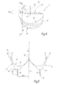
figure 6 is a view similar tofigure 2 for a turbine wheel according to a second embodiment of the invention. - In
figure 1 , a Pelton turbine T comprises a wheel R capable of rotating around a horizontal axis of rotation X-X, defined by a shaft A, under the effect of four jets ofwater 10. The turbine T also comprises fourinjectors 11 capable of producing the jets ofwater 10 and orienting them toward the wheel R. - The water used to produce the jets of
water 10 generally comes from a reservoir (not shown) and is guided toward theinjectors 11 via conduits (not shown). Theinjectors 11 belong to a water distribution unit that is known in itself and is not shown in detail. Theinjectors 11 are capable of accelerating water coming from the reservoir and thus converting the potential energy of the water into kinetic energy, via thejets 10. - The wheel R comprises a
hub 12, fastened to the shaft A, andseveral buckets 14. Thebuckets 14 are fastened to thehub 12 in the vicinity of afastening area 16. Thehub 12 and thebuckets 14 form a unitary structure. - The
buckets 14 are intended to receive the jets ofwater 10, which come into contact with thebuckets 14 with significant kinetic energy, so as to initiate and maintain the rotation of the wheel R around the axis X-X, in the direction of the arrow F1 offigure 1 . - Thus, the turbine T is capable of converting the kinetic energy of the jets of
water 10 into mechanical energy transmitted to thehub 12 and the shaft A. - The buckets are identical.
- Each
bucket 14 is positioned, in a direction orthoradial to the axis of rotation X-X, between a precedingbucket 14' and a followingbucket 14". This is shown infigure 2 for the bucket visible only infigures 3 to 5 . - Each
bucket 14 comprises astructural portion 18, for transmitting the force exerted by the jets ofwater 10 on thebucket 14, when it comes into contact with thebucket 14. Thestructural portion 18 guarantees the mechanical properties of thebucket 14. It defines anintrados surface 20 turned toward the precedingbucket 14' and intended to receive the jets ofwater 10 and anextrados surface 22 turned toward the followingbucket 14". Thestructural portion 18 is made from a first material allowing it to withstand intense dynamic forces, for example made from steel of type ASTM A743 CA6NM. - The
structural portion 18 of eachbucket 14 also comprises atrailing edge 24 that connects theintrados surface 20 and theextrados surface 22 to the periphery of the bucket and to at least oneheel 26 for stiffening thebucket 14, arranged on itsextrados surface 22. More specifically, and as shown infigures 3 and5 , eachbucket 14 comprises twostiffening heels 26. - Furthermore, each
bucket 14 comprises twofirst parts 30 each attached in the vicinity of adifferent heel 26 and which extend beyond thatheel 26, in the orthoradial direction and toward the followingbucket 14". - Alternatively, first attached
parts 30 are fastened on theextrados surface 22. - Each
bucket 14 also comprises twosecond parts 32 attached on thestructural portion 18 in the vicinity of thetrailing edge 24 and which extend beyond thetrailing edge 24, in the orthoradial direction and toward the precedingbucket 14'. - To facilitate their identification, the
parts figures 2 and 3 . - Each
bucket 14 comprises, on the side of itsintrados surface 20, acentral rim 34 that extends in a radial direction relative to the axis of rotation X-X of the wheel R. The central rim divides thebucket 14 in two, along the plane P comprising thecentral rim 34 and the orthoradial direction. - The
trailing edge 24 of eachbucket 14 comprises, on either side of the plane P, first 38 and second 40 outer radial zones that correspond to the two zones of thetrailing edge 24 furthest from the axis X-X. The rest of thetrailing edge 24 defines an innerradial zone 42. - The
stiffening heels 26 are positioned on either side of thecentral rim 34, i.e., on either side of the plane P. Thus, the first attachedparts 30 are positioned on either side of thecentral rim 34. - The first attached
parts 30, as well as the second attachedparts 32, are made from a second material, different from the first material making up thestructural portion 18 of eachbucket 14. The first 30 and second 32 attached parts are intended to perform an aerodynamic function and do not have a mechanical function similar to that of thestructural portion 18. Thus, the first 30 and second 32 parts form a light structure compared to thestructural portion 18. The first 30 and second 32 parts are for example made from canvas, sheet metal or a composite material. - For each
bucket 14, the first andsecond parts water 10 received in thebucket 14. More specifically, the first andsecond parts jets 10 with respect to the aeraulic disruptions outside the wheel R. - Each
first part 30 is attached in the vicinity of adifferent stiffening heel 26 and therefore on either side of thecentral rim 34. If it is made from metal, thefirst part 30 may be welded on theheel 26 that it extends. Alternatively, the first part is glued or assembled by bolting on thestructural portion 18. - Each first part is formed by a globally
planar fin 30 perpendicular to the axis of rotation X-X of the wheel R. - Wmax denotes the maximum width of the
intrados surface 20 of thebuckets 14, measured parallel to the axis of rotation X-X of the wheel R. - The length L30 of each
fin 30, measured in a radial direction relative to the axis of rotation X-X of the wheel R, is comprised between 10% and 120% of the maximum width Wmax of theintrados surface 20 of thebuckets 14. Preferably, the ratio L30/Wmax is comprised between 50% and 100%. - H30 denotes the maximum height of each
fin 30, measured in the orthoradial direction, i.e., the maximum distance between anouter edge 43 of that fin opposite theheel 26 on which it is fastened, on the one hand, and that heel on the other hand. This maximum height is comprised between 10% and 70% of the maximum width Wmax of theintrados surface 20. Preferably, the ratio H30/Wmax is comprised between 30% and 50%. More generally, the maximum height H30 of eachfin 30 is limited, such that thefin 30 is not in contact with theintrados side 20 of the followingbucket 14" and does not disturb the flow of water at the followingbucket 14. - Furthermore, for each
bucket 14, the distance D30 between eachfin 30 and thecentral rim 34, measured along the axis of rotation X-X of the wheel R, is comprised between 20% and 50% of the maximum width Wmax of theintrados surface 20 of thebucket 14. Preferably, the ratio D30/Wmax is comprised between 20% and 35%. - The two
fins 30 of eachbucket 14 are respectively positioned on adifferent heel 26 and define a first space E1 between them, through which the jets ofwater 10 oriented toward the followingbucket 14" are intended to pass and inside which thosejets 10 are confined, as shown by ajet 10 infigure 3 . - Furthermore, the surface area S30 of each
fin 30 in a plane perpendicular to the axis of rotation X-X is comprised between 10% and 70% of the maximum width Wmax of theintrados side 20 of the correspondingbucket 14 squared. Preferably, the ratio S30/Wmax 2 is comprised between 30% and 50%. More generally, the surface has sufficient dimensions to protect thejet 10 from outside aerodynamic disruptions. - In
figures 2 and4 , it will be noted that theouter edge 43 of thefin 30, furthest from theextrados surface 22 in the orthoradial direction, is generally in the shape of an arc of circle. - The
second parts 32 are attached on eachbucket 14 respectively in the vicinity of the first 38 and second 40 outer radial zones. Depending on the nature of the second material from which it is made, the second parts may also be welded, glued or bolted on thestructural portion 18. - The
second parts 32 are attached on the outside of the trailingedge 24. They extend beyond outerradial zones bucket 14'. More specifically, for eachbucket 14, eachsecond part 32 comprises an outerradial end 44 adjoining an outerradial end 46 of the trailingedge 24, and an innerradial end 48, closer to afastening area 16 of thebucket 14 on thehub 12, than the outerradial end 44. Thus, for eachbucket 14, eachsecond part 32 extends between the outerradial end 44 and the innerradial end 48. More generally, the trailingedge 24 of eachbucket 14 comprises two outer radial ends 46 respectively belonging to the first 38 and second 40 outer radial zones. These two outerradial zones 46 each adjoin the outerradial end 44 of a differentsecond part 32. - The length L32 over which each
second part 32 extends, measured in a radial direction relative to the axis of rotation X-X of the wheel R, is comprised between 10% and 70% of the maximum width Wmax.. Preferably, the ratio L32/Wmax is comprised between 40% and 70%. - The two
second parts 32 of eachbucket 14 are respectively attached in the vicinity of the first 38 and second 40 outer radial zones, since the distance between the trailingedge 24, thebucket 14, and the precedingbucket 14', measured in a direction orthoradial to the axis of rotation X-X in the vicinity of theinner radial zone 42, is generally very limited. - Furthermore, the raising height H32 of each
second part 32, measured relative to the corresponding trailingedge 24, in the orthoradial direction and toward the precedingbucket 14', increases from the innerradial end 48 toward the outerradial end 44. The maximum raising height H32max, considered at theend 44, is comprised between 5% and 50% of the maximum width Wmax of theintrados side 20. Preferably, the ratio H32max/Wmax is comprised between 20% and 40%. - The two
second parts 32 define a second space E2 for confining jets ofwater 10, turned toward the precedingbucket 14'. - Thus, when the jets of
water 10 pass through the first space E1 of onebucket 14 and the second space E2 of a followingbucket 14", the jet is respectively confined between thefins 30 and thesecond parts 32 and thus protected from aerodynamic disruptions related to flows of air present around thebuckets 14. - The
second parts 32 are comparable to an extension of the extrados side of eachbucket 14 toward the precedingbucket 14'. - Alternatively, the
second parts 32 form aerodynamic surfaces, such as ribs, capable of controlling the flow of air and optimizing the aerodynamic behavior of the wheel R and, more specifically, of eachbucket 14. - The maximum distance measured in a radial direction between the axis of rotation X-X of the wheel R and each
first part 30 and eachsecond part 32 is smaller than the maximum radius of the wheel R, measured between the axis of rotation and one of the outer radial ends 46 of a trailingedge 24. Thus, the first 30 and second 32 parts do not come into contact with the components of the turbine T positioned in the vicinity of the wheel R, such as theinjectors 11. - Owing to the first 30 and second 32 parts, the confinement of the jets of
water 10 is optimized and their initial shape at the outlet of theinjectors 11 is preserved until they come into contact with theintrados side 20 of a bucket. - The
second parts 32 advantageously make it possible to capture or accelerate the air surrounding them, so as to limit the turbulence surrounding thejet 10. The flow of air circulating around the wheel R is thus controlled and the aerodynamic behavior of thebuckets 14 of the wheel R is optimized. - Alternatively, each
bucket 14 comprises only the twofirst parts 30 or the twosecond parts 32. - According to another alternative, each
bucket 14 comprises only the twofirst parts 30 that are attached on the following bucket in the vicinity of its trailingedge 24. In a view comparable tofigure 3 , thefirst parts 30 then diverge downwardly to be attached on the trailingedge 24 of the followingbucket 14". In that case, these parts are bent and no longer planar. -
Figure 6 shows a second embodiment of the invention in which the elements generally similar to a first embodiment bear the same references. In this figure, theparts figure 2 . In this embodiment, thefirst parts 30 have a different shape from those of the first embodiment. More specifically, theouter edge 43 of eachend 30, furthest from theextrados surface 22, has a generally rectilinear shape. - Thus, according to the considered embodiment, the surface S30 of the
first parts 30 is different and the jets ofwater 10 are more or less confined when they pass through the first space E1. The second embodiment has substantially the same advantages as the first embodiment. - Alternatively, the stiffening
heels 26 are merged with thestructural portion 18. In this alternative, thefins 30 are fastened on the extrados surface, while extending beyond the extrados surface, in the orthoradial direction and towards the followingbucket 14". In this alternative, the two fins are positioned on either side of thecentral rim 34. - The embodiments and alternatives mentioned above may be combined with each other or modified to create other embodiments of the invention.
Claims (10)
- A Pelton turbine wheel (R) comprising several buckets (14), each bucket (14) being positioned, in a direction orthoradial to an axis of rotation (X-X) of the wheel, between a preceding bucket (14') and a following bucket (14") and comprising:- a structural force-transmitting portion (18) made from a first material and which defines an intrados surface (20) turned toward the preceding bucket (14') and intended to receive a jet of water (10), and an extrados surface (22) turned toward the following bucket (14"), and- a trailing edge (24) that connects the intrados surface (20) and the extrados surface (22),characterized in that each bucket (14) comprises at least one part (30, 32) made from a second material different from the first material, in that that part (30, 32) is fastened on the structural portion (18):- either in the vicinity of the trailing edge (24), while extending beyond the trailing edge, in the orthoradial direction and toward the preceding bucket (14'),- or on the extrados surface (22), while extending beyond the extrados surface, in the orthoradial direction and toward the following bucket (14"),
and in that the attached part (30, 32) forms a screen to participate in confining the jet of water received in the bucket (14). - The wheel according to claim 1, characterized in that each bucket (14) comprises two first attached parts (30) each on the extrados surface (22) and extending beyond that extrados surface, in the orthoradial direction and toward the following bucket (14").
- The wheel according to claim 2, characterized in that each first attached part is formed by a globally planar fin (30) perpendicular to the axis of rotation (X-X) of the wheel, and in that the length (L30) of each fin, measured in a radial direction relative to the axis of rotation of the wheel, is comprised between 10% and 120% of the maximum width (Wmax) of the intrados surface (20) of the bucket (14), measured parallel to the axis of rotation of the wheel.
- The wheel according to claim 3, characterized in that the maximum height (H30) of each fin, measured in the orthoradial direction, is comprised between 10% and 70% of the maximum width (Wmax) of the intrados surface (20) of the bucket (14).
- The wheel according to one of claims 3 or 4, characterized in that each bucket (14) comprises a central rim (34) extending in a radial direction relative to the axis of rotation (X-X) of the wheel, in that the two fins (30) are positioned on either side of the central rim (34) and in that the distance (D30) between each fin (30) and the central rim, measured along the axis of rotation of the wheel, is comprised between 20% and 50% of the maximum width (Wmax) of the intrados surface (20) of the bucket (14).
- The wheel according to one of claims 3 to 5, characterized in that the surface area (S30) of each fin, in a plane perpendicular to the axis of rotation (X-X) of the wheel, is comprised between 10% and 70% of the maximum width (Wmax) of the intrados surface (20) of the corresponding bucket (14) squared.
- The wheel according to one of the preceding claims, characterized in that the trailing edge (24) of each bucket (14) comprises first (38) and second (40) outer radial zones, and in that each bucket (14) comprises a second attached part (32) respectively in the vicinity of the first and second outer radial zones and in that the second attached parts extend beyond those outer radial zones, in the orthoradial direction and toward the preceding bucket (14').
- The wheel according to claim 7, characterized in that each second attached part (32) extends between an outer radial end (44) adjoining an outer radial end (46) of the trailing edge (24) and an inner radial end (48), closer to a fastening area (16) of the bucket to a hub (12) of the wheel than the outer radial end (46), over a length (L32), measured in a radial direction relative to the axis of rotation (X-X) of the wheel, comprised between 10% and 70% of the maximum width (Wmax) of the intrados surface of the bucket (14), measured along the axis of rotation of the wheel.
- The wheel according to claim 8, characterized in that a raising height (H32) of each second attached part (32) relative to the trailing edge (24), measured in the orthoradial direction, increases from the inner radial end (48) toward the outer radial end (44), and in that the maximum raising height (H32max) is comprised between 5% and 50% of the maximum width (Wmax) of the intrados surface (20) of the bucket (14).
- A Pelton turbine (T) comprising a distribution unit (11) for supplying water to a Pelton turbine wheel, characterized in that the Pelton turbine wheel (R) is according to one of claims 1 to 9.
Priority Applications (1)
| Application Number | Priority Date | Filing Date | Title |
|---|---|---|---|
| EP20130306481 EP2868912A1 (en) | 2013-10-30 | 2013-10-30 | Pelton turbine wheel and pelton turbine comprising such a wheel |
Applications Claiming Priority (1)
| Application Number | Priority Date | Filing Date | Title |
|---|---|---|---|
| EP20130306481 EP2868912A1 (en) | 2013-10-30 | 2013-10-30 | Pelton turbine wheel and pelton turbine comprising such a wheel |
Publications (1)
| Publication Number | Publication Date |
|---|---|
| EP2868912A1 true EP2868912A1 (en) | 2015-05-06 |
Family
ID=49584673
Family Applications (1)
| Application Number | Title | Priority Date | Filing Date |
|---|---|---|---|
| EP20130306481 Withdrawn EP2868912A1 (en) | 2013-10-30 | 2013-10-30 | Pelton turbine wheel and pelton turbine comprising such a wheel |
Country Status (1)
| Country | Link |
|---|---|
| EP (1) | EP2868912A1 (en) |
Cited By (3)
| Publication number | Priority date | Publication date | Assignee | Title |
|---|---|---|---|---|
| WO2020060387A1 (en) * | 2018-09-19 | 2020-03-26 | Tnb Research Sdn Bhd | Impulse hydro turbine system |
| CN113775459A (en) * | 2021-10-20 | 2021-12-10 | 哈尔滨电机厂有限责任公司 | Pelton turbine hub with support structure |
| WO2023235905A1 (en) | 2022-06-07 | 2023-12-14 | Andritz Hydro Gmbh | Blade of a pelton turbine |
Citations (5)
| Publication number | Priority date | Publication date | Assignee | Title |
|---|---|---|---|---|
| GB715858A (en) * | 1952-06-06 | 1954-09-22 | English Electric Co Ltd | Improvements in and relating to impulse wheel runners |
| AT184527B (en) * | 1952-04-09 | 1956-01-25 | Markham And Company Ltd | Bucket wheel |
| US20040120821A1 (en) | 2001-05-11 | 2004-06-24 | Lothar Geppert | Pelton bucket |
| DE102009004816A1 (en) * | 2009-01-13 | 2010-07-15 | Voith Patent Gmbh | Free turbine |
| EP2213407A1 (en) * | 2009-01-30 | 2010-08-04 | Alstom Hydro France | Hydraulic machine newly manufactured component, method for manufacturing or repairing such a component |
-
2013
- 2013-10-30 EP EP20130306481 patent/EP2868912A1/en not_active Withdrawn
Patent Citations (5)
| Publication number | Priority date | Publication date | Assignee | Title |
|---|---|---|---|---|
| AT184527B (en) * | 1952-04-09 | 1956-01-25 | Markham And Company Ltd | Bucket wheel |
| GB715858A (en) * | 1952-06-06 | 1954-09-22 | English Electric Co Ltd | Improvements in and relating to impulse wheel runners |
| US20040120821A1 (en) | 2001-05-11 | 2004-06-24 | Lothar Geppert | Pelton bucket |
| DE102009004816A1 (en) * | 2009-01-13 | 2010-07-15 | Voith Patent Gmbh | Free turbine |
| EP2213407A1 (en) * | 2009-01-30 | 2010-08-04 | Alstom Hydro France | Hydraulic machine newly manufactured component, method for manufacturing or repairing such a component |
Cited By (4)
| Publication number | Priority date | Publication date | Assignee | Title |
|---|---|---|---|---|
| WO2020060387A1 (en) * | 2018-09-19 | 2020-03-26 | Tnb Research Sdn Bhd | Impulse hydro turbine system |
| CN113775459A (en) * | 2021-10-20 | 2021-12-10 | 哈尔滨电机厂有限责任公司 | Pelton turbine hub with support structure |
| CN113775459B (en) * | 2021-10-20 | 2023-03-10 | 哈尔滨电机厂有限责任公司 | Pelton turbine hub with support structure |
| WO2023235905A1 (en) | 2022-06-07 | 2023-12-14 | Andritz Hydro Gmbh | Blade of a pelton turbine |
Similar Documents
| Publication | Publication Date | Title |
|---|---|---|
| US6582196B1 (en) | Windmill rotor and wind blades therefor | |
| US7345376B2 (en) | Passively cooled direct drive wind turbine | |
| KR101258049B1 (en) | Turbine blade-cascade end wall | |
| KR102143165B1 (en) | Wind power generation equipment-rotor blades and wind power generation equipment including the same | |
| US9523279B2 (en) | Rotor blade fence for a wind turbine | |
| KR20130112770A (en) | Flatback slat for wind turbine | |
| US20140294592A1 (en) | Acoustic shield for noise reduction in wind turbines | |
| JP6746552B2 (en) | Wind power generator | |
| EP2868912A1 (en) | Pelton turbine wheel and pelton turbine comprising such a wheel | |
| US9175668B2 (en) | Hub for wind turbine rotor | |
| WO2013129046A1 (en) | Windmill rotating blade and wind power generating windmill | |
| US20120321482A1 (en) | Wind turbine blade | |
| CN102852720A (en) | Wind turbine and an associated yaw control method | |
| US20140286787A1 (en) | Blade for a wind turbine having a guide vane | |
| US20160230740A1 (en) | Vertical axis wind turbine rotor | |
| EP3112669B1 (en) | Pitch assembly for a wind turbine rotor blade | |
| EP2923077B1 (en) | Wind turbine rotor and methods of assembling the same | |
| US10240579B2 (en) | Apparatus and method for aerodynamic performance enhancement of a wind turbine | |
| EP2937557B1 (en) | Wind wheel (with two alternatives) | |
| KR20120127013A (en) | Windmill | |
| KR101794818B1 (en) | Blade for wind power generation | |
| KR101291116B1 (en) | blade of wind powergenerator and powergenerator | |
| EP2851556A1 (en) | Arrangement to reduce noise of a wind turbine rotor blade | |
| CN112639283B (en) | Rotor blade, wind energy plant and method for optimizing a wind energy plant | |
| US10533449B2 (en) | Containment for a continuous flow machine |
Legal Events
| Date | Code | Title | Description |
|---|---|---|---|
| PUAI | Public reference made under article 153(3) epc to a published international application that has entered the european phase |
Free format text: ORIGINAL CODE: 0009012 |
|
| 17P | Request for examination filed |
Effective date: 20131030 |
|
| AK | Designated contracting states |
Kind code of ref document: A1 Designated state(s): AL AT BE BG CH CY CZ DE DK EE ES FI FR GB GR HR HU IE IS IT LI LT LU LV MC MK MT NL NO PL PT RO RS SE SI SK SM TR |
|
| AX | Request for extension of the european patent |
Extension state: BA ME |
|
| STAA | Information on the status of an ep patent application or granted ep patent |
Free format text: STATUS: THE APPLICATION IS DEEMED TO BE WITHDRAWN |
|
| 18D | Application deemed to be withdrawn |
Effective date: 20151107 |