EP2868910A1 - Silencer for supercharger - Google Patents
Silencer for supercharger Download PDFInfo
- Publication number
- EP2868910A1 EP2868910A1 EP20140822436 EP14822436A EP2868910A1 EP 2868910 A1 EP2868910 A1 EP 2868910A1 EP 20140822436 EP20140822436 EP 20140822436 EP 14822436 A EP14822436 A EP 14822436A EP 2868910 A1 EP2868910 A1 EP 2868910A1
- Authority
- EP
- European Patent Office
- Prior art keywords
- suction
- turbocharger
- silencer
- air
- sound absorbing
- Prior art date
- Legal status (The legal status is an assumption and is not a legal conclusion. Google has not performed a legal analysis and makes no representation as to the accuracy of the status listed.)
- Withdrawn
Links
- 230000003584 silencer Effects 0.000 title claims abstract description 88
- 238000002485 combustion reaction Methods 0.000 description 7
- 238000011144 upstream manufacturing Methods 0.000 description 3
- 229910052751 metal Inorganic materials 0.000 description 2
- 239000002184 metal Substances 0.000 description 2
- 238000000926 separation method Methods 0.000 description 2
- 229910052782 aluminium Inorganic materials 0.000 description 1
- XAGFODPZIPBFFR-UHFFFAOYSA-N aluminium Chemical compound [Al] XAGFODPZIPBFFR-UHFFFAOYSA-N 0.000 description 1
- 238000010586 diagram Methods 0.000 description 1
- 230000000694 effects Effects 0.000 description 1
- 238000001914 filtration Methods 0.000 description 1
- 230000002452 interceptive effect Effects 0.000 description 1
- 238000004080 punching Methods 0.000 description 1
Images



Classifications
-
- F—MECHANICAL ENGINEERING; LIGHTING; HEATING; WEAPONS; BLASTING
- F04—POSITIVE - DISPLACEMENT MACHINES FOR LIQUIDS; PUMPS FOR LIQUIDS OR ELASTIC FLUIDS
- F04D—NON-POSITIVE-DISPLACEMENT PUMPS
- F04D29/00—Details, component parts, or accessories
- F04D29/40—Casings; Connections of working fluid
- F04D29/42—Casings; Connections of working fluid for radial or helico-centrifugal pumps
- F04D29/44—Fluid-guiding means, e.g. diffusers
- F04D29/441—Fluid-guiding means, e.g. diffusers especially adapted for elastic fluid pumps
- F04D29/444—Bladed diffusers
-
- F—MECHANICAL ENGINEERING; LIGHTING; HEATING; WEAPONS; BLASTING
- F02—COMBUSTION ENGINES; HOT-GAS OR COMBUSTION-PRODUCT ENGINE PLANTS
- F02M—SUPPLYING COMBUSTION ENGINES IN GENERAL WITH COMBUSTIBLE MIXTURES OR CONSTITUENTS THEREOF
- F02M35/00—Combustion-air cleaners, air intakes, intake silencers, or induction systems specially adapted for, or arranged on, internal-combustion engines
- F02M35/12—Intake silencers ; Sound modulation, transmission or amplification
- F02M35/1205—Flow throttling or guiding
- F02M35/1211—Flow throttling or guiding by using inserts in the air intake flow path, e.g. baffles, throttles or orifices; Flow guides
-
- F—MECHANICAL ENGINEERING; LIGHTING; HEATING; WEAPONS; BLASTING
- F02—COMBUSTION ENGINES; HOT-GAS OR COMBUSTION-PRODUCT ENGINE PLANTS
- F02M—SUPPLYING COMBUSTION ENGINES IN GENERAL WITH COMBUSTIBLE MIXTURES OR CONSTITUENTS THEREOF
- F02M35/00—Combustion-air cleaners, air intakes, intake silencers, or induction systems specially adapted for, or arranged on, internal-combustion engines
- F02M35/12—Intake silencers ; Sound modulation, transmission or amplification
- F02M35/1205—Flow throttling or guiding
- F02M35/1216—Flow throttling or guiding by using a plurality of holes, slits, protrusions, perforations, ribs or the like; Surface structures; Turbulence generators
-
- F—MECHANICAL ENGINEERING; LIGHTING; HEATING; WEAPONS; BLASTING
- F02—COMBUSTION ENGINES; HOT-GAS OR COMBUSTION-PRODUCT ENGINE PLANTS
- F02M—SUPPLYING COMBUSTION ENGINES IN GENERAL WITH COMBUSTIBLE MIXTURES OR CONSTITUENTS THEREOF
- F02M35/00—Combustion-air cleaners, air intakes, intake silencers, or induction systems specially adapted for, or arranged on, internal-combustion engines
- F02M35/12—Intake silencers ; Sound modulation, transmission or amplification
- F02M35/1288—Intake silencers ; Sound modulation, transmission or amplification combined with or integrated into other devices ; Plurality of air intake silencers
-
- F—MECHANICAL ENGINEERING; LIGHTING; HEATING; WEAPONS; BLASTING
- F04—POSITIVE - DISPLACEMENT MACHINES FOR LIQUIDS; PUMPS FOR LIQUIDS OR ELASTIC FLUIDS
- F04D—NON-POSITIVE-DISPLACEMENT PUMPS
- F04D29/00—Details, component parts, or accessories
- F04D29/66—Combating cavitation, whirls, noise, vibration or the like; Balancing
- F04D29/661—Combating cavitation, whirls, noise, vibration or the like; Balancing especially adapted for elastic fluid pumps
- F04D29/663—Sound attenuation
-
- F—MECHANICAL ENGINEERING; LIGHTING; HEATING; WEAPONS; BLASTING
- F05—INDEXING SCHEMES RELATING TO ENGINES OR PUMPS IN VARIOUS SUBCLASSES OF CLASSES F01-F04
- F05D—INDEXING SCHEME FOR ASPECTS RELATING TO NON-POSITIVE-DISPLACEMENT MACHINES OR ENGINES, GAS-TURBINES OR JET-PROPULSION PLANTS
- F05D2220/00—Application
- F05D2220/40—Application in turbochargers
-
- F—MECHANICAL ENGINEERING; LIGHTING; HEATING; WEAPONS; BLASTING
- F05—INDEXING SCHEMES RELATING TO ENGINES OR PUMPS IN VARIOUS SUBCLASSES OF CLASSES F01-F04
- F05D—INDEXING SCHEME FOR ASPECTS RELATING TO NON-POSITIVE-DISPLACEMENT MACHINES OR ENGINES, GAS-TURBINES OR JET-PROPULSION PLANTS
- F05D2250/00—Geometry
- F05D2250/50—Inlet or outlet
- F05D2250/51—Inlet
Definitions
- the present invention relates to a turbocharger silencer to be applied to a turbocharger of a large bore diesel engine, such as a ship's engine, and particularly to the structure of a turbocharger silencer that is provided with a suction housing.
- Turbochargers that compress combustion air for an internal combustion engine and send high-density air to a combustion chamber have been conventionally known and are also widely used, for example, in ship diesel engines or large bore diesel engines for power plants.
- a compressor for compressing combustion air and a turbocharger turbine serving as a driving source of the compressor are coaxially connected and accommodated in a casing and are rotated as a single unit. Note that the turbocharger turbine is driven by the energy of exhaust gas from the internal combustion engine.
- a turbocharger silencer disclosed, for example, in PTL 1 is used in order to reduce noise produced by suction air.
- sound absorbing splitters each having a double-bent shape (substantially Z-shape) are applied as silencer elements (sound absorbing bodies) to maintain the noize reduction performance and achieve a small pressure loss.
- the sound absorbing splitters are arranged in a suction air passage so that a plurality of the sound absorbing splitters are combined in the same direction.
- sound absorbing splitters 2 are radially directed at an inlet portion of the suction air passage and arranged in a circumferential direction, with spaces therebetween.
- silencer elements obtained by combining sound absorbing splitters each having a curved shape (arc-like shape etc.) instead of a substantially Z-shape are employed.
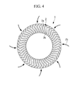
- a general turbocharger-silencer structure of a ship's engine has no air suction housing, as described in Fig. 4 illustrating a turbocharger silencer 1, for example.
- this silencer is of an inboard air suction type having a structure for suctioning air from radial directions with reference to a rotor shaft.
- a turbocharger-silencer structure of an outboard air suction type in which a duct for suctioning air is provided to suction air (outside air) directly from the outside of a ship, low-temperature air can be supplied from the outside of the ship to a turbocharger, thus increasing the combustion efficiency of the engine.
- a duct (not shown) through which suction air flows is connected to a suction housing H that is provided so as to surround a silencer main body (the turbocharger silencer 1 shown in Fig. 4 ), for example, as shown in Fig. 5 .
- silencer elements such as the sound absorbing splitters 2 disclosed in the above-described PTL 1
- the turbocharger silencer 1 of the inboard air suction type which does not have the suction housing H as shown in Figs. 1 and 5 of this application
- suction air passes from the same directions as suction-air flow directions of the silencer elements, as indicated by arrows F1 in Fig. 4 .
- the turbocharger silencer 1 of the inboard air suction type allows almost uniform suctioning over the entire circumference of the silencer.
- the suctioning state of suction air at the circumference of the silencer is non-uniform relative to an axial line L of a suction-air inlet Hi formed in the suction housing H.
- the suction housing H because the flow direction of suction air is limited by the suction housing H, the relationships between the cross-sectional shapes of the sound absorbing splitters 2 and suction-air flow directions F2 at both sides relative to the axial line L are substantially opposite between the both sides of the axial line L.
- the suctioning state of suction air becomes non-uniform at the circumference of the turbocharger silencer 1.
- the conventional turbocharger silencer 1A having the suction housing H there is a risk that the pressure loss in the silencer is increased, thereby reducing the turbocharger performance.
- turbocharger silencer 1A having the suction housing H it is desired to achieve an improvement in turbocharger performance by improving the arrangement structure of silencer elements, such as the sound absorbing splitters 2 having suction-air flow directions.
- the present invention is made in view of the above-described circumstances, and an object thereof is to provide a turbocharger silencer of an outboard air suction type having a suction housing, which is capable of resolving a situation in which the suctioning state of suction air at the circumference of the silencer becomes non-uniform relative to the axial line of a suction air inlet.
- the present invention employs the following solutions.
- the present invention provides a turbocharger silencer that includes a suction housing coupled to an outside-air introducing duct and that is attached to an air suction port of a turbocharger main body, wherein the turbocharger silencer reduces noise of suction air introduced from a radially outward positon with reference to a rotor shaft of the turbocharger main body, wherein a plurality of silencer elements are arranged radially with reference to the rotor shaft of the turbocharger main body and are disposed such that the directions of apexes of some silencer elements of the plurality of silencer elements are different from those of apexes of the rest of the silencer elements.
- the plurality of silencer elements are arranged radially with reference to the rotor shaft of the turbocharger main body and are disposed such that the directions of apexes of some silencer elements of the plurality of silencer elements are different from those of apexes of the rest of the silencer elements.
- the number of the silencer elements whose cross-sectional shapes have directions opposite to the suction-air flow directions are reduced, thereby making it possible to prevent a situation in which the suctioning state of suction air becomes non-uniform.
- the plurality of silencer elements be arranged such that the directions of the apexes of the plurality of silencer elements with reference to the rotor shaft are different between the two sides of an axial line of a suction-air inlet opening of the suction housing.
- a partiton plate for preventing interference of flows of suction air in the suction housing.
- a turbocharger according to the present invention includes a turbocharger silencer according to any one of the aforementioned configurations. Therefore, the number of the silencer elements whose cross-sectional shapes have directions opposite to the suction-air flow directions are reduced, thereby making it possible to prevent a situation in which the suctioning state of suction air becomes non-uniform.
- a turbocharger silencer according to an embodiment of the present invention will be described below with reference to Figs. 1 to 3 .
- Fig. 3 is a longitudinal sectional view showing an example structure of an exhaust gas turbine turbocharger provided with the turbocharger silencer of the present invention, and the turbocharger silencer of the present invention can be applied to such an exhaust gas turbine turbocharger 10.
- the exhaust gas turbine turbocharger 10, shown in the figure, is an apparatus to be mounted, for example, on a ship diesel engine (for example, a low-speed two-cycle diesel engine) (not shown) to supply compressed air to an air supply manifold (not shown) that communicates with the inside of cylinder liners (not shown) that constitute the ship diesel engine.
- a ship diesel engine for example, a low-speed two-cycle diesel engine
- an air supply manifold not shown
- cylinder liners not shown
- the exhaust gas turbine turbocharger 10 is constituted by integrally-fastening a gas inlet casing 11, a gas outlet casing 12, a bearing housing 13, and a compressor-side air guiding casing 14 with bolts (not shown).
- a rotor shaft 15 is rotatably supported in the bearing housing 13 by a thrust bearing 16 and radial bearings 17 and 18, one end of the rotor shaft 15 is fixedly coupled to a turbine 19 that constitutes a turbine section, and the other end thereof is fixedly coupled to a compressor impeller (impeller) 20 that constitutes a compressor section.
- the turbine 19, which is located at the one end of the rotor shaft 15, has a number of blades 19a on its outer periphery.
- the blades 19a are located between an exhaust-gas introduction passage 22 that is provided in the gas inlet casing 11 and an exhaust-gas discharge passage 23 that is provided in the gas outlet casing 12.
- the compressor impeller 20 which is located at the other end of the rotor shaft 15, has a number of blades 20a on its outer periphery.
- the blades 20a are located at the downstream postion of a suction-air introduction passage (suction air passage) 24 that is provided in the air guiding casing 14.
- the suction-air introduction passage 24 is connected to a scroll chamber 25 via the compressor impeller 20.
- the scroll chamber 25 is connected to a combustion chamber of the engine via a suction-air introduction passage (not shown).
- the above-described exhaust gas turbine turbocharger 10 is provided with a turbocharger silencer 30 at an upstream side of the suction-air introduction passage 24.
- the turbocharger silencer 30 is an apparatus to be mounted at a stage (at an upstream side) before suction air to be compressed by the compressor section is suctioned into the suction-air introduction passage 24, specifically, at an upstream side of the inlet of the suction-air introduction passage 24, and has a filtering function for rectifying an airflow by making suction air pass therethrough and a noize reduction function for absorbing noise produced by introducing air.
- an outside-air introducing duct (not shown) for introducing low-temperature air from the outside of the ship is connected to a suction housing (air suction housing) H that is provided so as to surround the outer periphery of a silencer main body 31. Therefore, the turbine turbocharger 10 serves as a turbocharger silencer of an outboard air suction type having the suction housing H.
- the turbocharger silencer 30, shown in Fig. 1 is provided with the suction housing H, which is connected to the outside-air introducing duct, and is attached to an air suction port of the exhaust gas turbine turbocharger (turbocharger main body) 10, thereby reducing noise of suction air introduced from the radially outward with reference to the rotor shaft of the turbocharger main body via the suction-air introduction passage 24.
- a plurality of sound absorbing splitters 2 serving as silencer elements are installed at an inlet portion of the suction air passage 24.
- Outer peripheries of the sound absorbing splitters 2 that are located along the axial direction of the rotor shaft 15 and that are not opposed to wall surfaces 32 and 33 of the silencer main body 31 are made of metal such as aluminum, and the sound absorbing splitters 2 are respectively surrounded with outer periphery walls Pm made of punching metal in which a number of through-holes are formed. Furthermore, the outer periphery walls Pm of the sound absorbing splitters 2 each have two bent portions 2a and 2b that are formed so as to be bent in opposite directions from each other. Therefore, the sound absorbing splitters 2 each have a substantially Z-shape in cross section as a whole.
- These sound absorbing splitters 2 are arranged so as to reduce passage resistance with respect to the suction-air flow directions.
- apexes 2a of the bent portions each of the apexes 2a is the convex-shaped portion of the radially-outside bent portion of the two bent portions 2a and 2b
- the substantially Z-shape in cross section are arranged so as to be all pointing in one direction (more specifically, as shown in Fig.
- the apexes 2a of the bent portions of all of the sound absorbing splitters 2 are arranged so as to point to the left when viewed from the rotor shaft (in another example, the apexes 2a of the bent portions of all of the sound absorbing splitters 2 are arranged so as to point to the right when viewed from the rotor shaft), the passage resistance is reduced in a case in which the apexes 2a of the bent portions of the sound absorbing splitters 2 are arranged so as to point to downstream sides in the suction-air flow directions (that is, in the directions of arrows F3 shown in Fig. 1 ).
- the sound absorbing splitters 2 are arranged such that the directions of the apexes 2a of the bent portions of at least some of the sound absorbing splitters 2 are different from those of the other sound absorbing splitters 2, when viewed from the rotor shaft.
- the sound absorbing splitters 2 shown in Fig. 1 are arranged such that the directions of the apexes 2a of the bent portions of the sound absorbing splitters 2 are different with reference to the rotor shaft, between the two sides of an axial line L of a suction-air inlet opening Hi of the suction housing H (for example, an axial line passing through an axial line of the rotor shaft and the center of the suction-air inlet opening).
- the sound absorbing splitters 2 are arranged such that the directions of the apexes 2a of the bent portions of the sound absorbing splitters 2 are substantially symmetric in cross section with respect to the axial line L.
- the axial line L of the suction-air inlet opening Hi is provided at an axial-line inclination angle ⁇ 1 from a horizontal line.
- This axial-line inclination angle ⁇ 1 falls within the range from 0 to 90 degrees, and an angle ⁇ 2 on an outlet side falls within the range from 0 degrees to ⁇ 1. Therefore, when the axial-line inclination angle ⁇ 1 is almost 0 degree, the arrangement of the apexes 2a of the bent portions of the sound absorbing splitters 2 may be apparently substantially symmetric in the vertical direction and with respect to the axial line L.
- turbocharger silencer 30 of this embodiment may be provided with a partiton plate such that the flows of suction air do not interfere with each other in the suction housing. More preferably, a partiton plate 40 may be provided on the axial line L of the suction-air inlet opening Hi and at a position in the suction housing that is opposite to the position of the suction-air inlet opening Hi, to prevent the flows of suction air from interfering.
- the sound absorbing splitters 2 are arranged such that the apexes 2a thereof are all pointing to the downstream sides in the suction-air flow directions and are radially directed at the inlet portion of the suction air passage 24 and arranged in a circumferential direction, with spaces between the sound absorbing splitters 2.
- the silencer elements are symmetrically arranged with respect to the axial line L, the flow velocity distribution and the suction distribution of suction air in the suction housing H in a circumferential direction of the turbocharger silencer 30 are made uniform, thereby making it possible to prevent a reduction in turbocharger performance caused by flow separation or vortexes.
- the turbocharger to which the silencer of this embodiment is applied has improved supercharging efficiency at the time of low load compared with a conventional structure, as is clear from the test results shown in Fig. 2 .
- the present invention is not limited thereto, and it is needless to say that the present invention can be applied to other silencer elements having predetermined flow directions, such as those having arc-like cross sections, for example.
Landscapes
- Engineering & Computer Science (AREA)
- Mechanical Engineering (AREA)
- General Engineering & Computer Science (AREA)
- Chemical & Material Sciences (AREA)
- Combustion & Propulsion (AREA)
- Supercharger (AREA)
- Structures Of Non-Positive Displacement Pumps (AREA)
Abstract
Description
- The present invention relates to a turbocharger silencer to be applied to a turbocharger of a large bore diesel engine, such as a ship's engine, and particularly to the structure of a turbocharger silencer that is provided with a suction housing.
- Turbochargers that compress combustion air for an internal combustion engine and send high-density air to a combustion chamber have been conventionally known and are also widely used, for example, in ship diesel engines or large bore diesel engines for power plants. In such a turbocharger, a compressor for compressing combustion air and a turbocharger turbine serving as a driving source of the compressor are coaxially connected and accommodated in a casing and are rotated as a single unit. Note that the turbocharger turbine is driven by the energy of exhaust gas from the internal combustion engine.
- In conventional turbochargers, a turbocharger silencer disclosed, for example, in PTL 1 is used in order to reduce noise produced by suction air. In this turbocharger silencer, sound absorbing splitters each having a double-bent shape (substantially Z-shape) are applied as silencer elements (sound absorbing bodies) to maintain the noize reduction performance and achieve a small pressure loss. The sound absorbing splitters are arranged in a suction air passage so that a plurality of the sound absorbing splitters are combined in the same direction.
- Specifically, for example, in
turbocharger silencers 1 and 1A shown inFigs. 4 and5 ,sound absorbing splitters 2 are radially directed at an inlet portion of the suction air passage and arranged in a circumferential direction, with spaces therebetween. - Furthermore, in other turbocharger silencers, silencer elements obtained by combining sound absorbing splitters each having a curved shape (arc-like shape etc.) instead of a substantially Z-shape are employed.
- Furthermore, a general turbocharger-silencer structure of a ship's engine has no air suction housing, as described in
Fig. 4 illustrating a turbocharger silencer 1, for example. Thus, this silencer is of an inboard air suction type having a structure for suctioning air from radial directions with reference to a rotor shaft. - On the other hand, with a turbocharger-silencer structure of an outboard air suction type in which a duct for suctioning air is provided to suction air (outside air) directly from the outside of a ship, low-temperature air can be supplied from the outside of the ship to a turbocharger, thus increasing the combustion efficiency of the engine. In the
silencer 1A of the outboard air suction type, a duct (not shown) through which suction air flows is connected to a suction housing H that is provided so as to surround a silencer main body (the turbocharger silencer 1 shown inFig. 4 ), for example, as shown inFig. 5 . - {PTL 1} Japanese Unexamined Patent Application, Publication No.
H11-200969 - If silencer elements, such as the
sound absorbing splitters 2 disclosed in the above-described PTL 1, are applied to the turbocharger silencer 1 of the inboard air suction type, which does not have the suction housing H as shown inFigs. 1 and5 of this application, suction air passes from the same directions as suction-air flow directions of the silencer elements, as indicated by arrows F1 inFig. 4 . Thus, the turbocharger silencer 1 of the inboard air suction type allows almost uniform suctioning over the entire circumference of the silencer. - However, in the
turbocharger silencer 1A of the outboard air suction type having the suction housing H shown inFigs. 1 and5 of this application, the suctioning state of suction air at the circumference of the silencer is non-uniform relative to an axial line L of a suction-air inlet Hi formed in the suction housing H. Specifically, because the flow direction of suction air is limited by the suction housing H, the relationships between the cross-sectional shapes of thesound absorbing splitters 2 and suction-air flow directions F2 at both sides relative to the axial line L are substantially opposite between the both sides of the axial line L. Thus, the suctioning state of suction air becomes non-uniform at the circumference of the turbocharger silencer 1. As a result, in theconventional turbocharger silencer 1A having the suction housing H, there is a risk that the pressure loss in the silencer is increased, thereby reducing the turbocharger performance. - Considering such circumstances, in the
turbocharger silencer 1A having the suction housing H, it is desired to achieve an improvement in turbocharger performance by improving the arrangement structure of silencer elements, such as thesound absorbing splitters 2 having suction-air flow directions. - The present invention is made in view of the above-described circumstances, and an object thereof is to provide a turbocharger silencer of an outboard air suction type having a suction housing, which is capable of resolving a situation in which the suctioning state of suction air at the circumference of the silencer becomes non-uniform relative to the axial line of a suction air inlet.
- In order to solve the above-described problems, the present invention employs the following solutions.
- The present invention provides a turbocharger silencer that includes a suction housing coupled to an outside-air introducing duct and that is attached to an air suction port of a turbocharger main body, wherein the turbocharger silencer reduces noise of suction air introduced from a radially outward positon with reference to a rotor shaft of the turbocharger main body, wherein a plurality of silencer elements are arranged radially with reference to the rotor shaft of the turbocharger main body and are disposed such that the directions of apexes of some silencer elements of the plurality of silencer elements are different from those of apexes of the rest of the silencer elements.
- According to this turbocharger silencer, the plurality of silencer elements are arranged radially with reference to the rotor shaft of the turbocharger main body and are disposed such that the directions of apexes of some silencer elements of the plurality of silencer elements are different from those of apexes of the rest of the silencer elements. Thus, the number of the silencer elements whose cross-sectional shapes have directions opposite to the suction-air flow directions are reduced, thereby making it possible to prevent a situation in which the suctioning state of suction air becomes non-uniform.
- In the above-described invention, it is preferable that the plurality of silencer elements be arranged such that the directions of the apexes of the plurality of silencer elements with reference to the rotor shaft are different between the two sides of an axial line of a suction-air inlet opening of the suction housing. With this arrangement, it is possible to reliably prevent or reduce situations in which the silencer elements whose cross-sectional shapes have directions opposite to the suction-air flow directions. Then, because the flow velocity distribution of suction air is made uniform, and the suction distribution of suction air in the silencer also becomes uniform, it is possible to control a reduction in performance caused by separation or vortexes.
- Furthermore, in the above-described invention, it is desirable to further include a partiton plate for preventing interference of flows of suction air in the suction housing.
- A turbocharger according to the present invention includes a turbocharger silencer according to any one of the aforementioned configurations. Therefore, the number of the silencer elements whose cross-sectional shapes have directions opposite to the suction-air flow directions are reduced, thereby making it possible to prevent a situation in which the suctioning state of suction air becomes non-uniform.
- According to the above-described present invention, it is possible to resolve a situation in which the suction-air suctioning states produced on the right and left sides with reference to the axial line of an inlet of suction air become non-uniform in the turbocharger silencer having a suction housing, thus preventing an increase of pressure loss in the silencer and a reduction of turbocharger performance.
-
- {
Fig. 1} Fig. 1 is a longitudinal sectional view (cross-sectional view in a direction perpendicular to a rotor shaft) showing an example arrangement of silencer elements in a suction air passage of a turbocharger silencer according to an embodiment of the present invention. - {
Fig. 2} Fig. 2 is a diagram of a test result showing the relationship between the efficiency (vertical axis) and the compressor pressure ratio (horizontal axis) of a turbocharger provided with the turbocharger silencer shown inFig. 1 , comparing the result with that of a conventional structure. - {
Fig. 3} Fig. 3 is a longitudinal sectional view (cross-sectional view in the direction of the rotor shaft) showing an example structure of an exhaust gas turbine turbocharger provided with the turbocharger silencer of the present invention. - {
Fig. 4} Fig. 4 is a longitudinal sectional view showing an example conventional silencer-element arrangement in a turbocharger silencer of an inboard air suction type (without an air suction housing). - {
Fig. 5} Fig. 5 is a longitudinal sectional view showing an example conventional silencer-element arrangement in a turbocharger silencer of an outboard air suction type (with an air suction housing). - A turbocharger silencer according to an embodiment of the present invention will be described below with reference to
Figs. 1 to 3 . -
Fig. 3 is a longitudinal sectional view showing an example structure of an exhaust gas turbine turbocharger provided with the turbocharger silencer of the present invention, and the turbocharger silencer of the present invention can be applied to such an exhaustgas turbine turbocharger 10. - The exhaust
gas turbine turbocharger 10, shown in the figure, is an apparatus to be mounted, for example, on a ship diesel engine (for example, a low-speed two-cycle diesel engine) (not shown) to supply compressed air to an air supply manifold (not shown) that communicates with the inside of cylinder liners (not shown) that constitute the ship diesel engine. - As shown in
Fig. 3 , the exhaustgas turbine turbocharger 10 is constituted by integrally-fastening agas inlet casing 11, agas outlet casing 12, abearing housing 13, and a compressor-sideair guiding casing 14 with bolts (not shown). Arotor shaft 15 is rotatably supported in the bearinghousing 13 by a thrust bearing 16 andradial bearings rotor shaft 15 is fixedly coupled to aturbine 19 that constitutes a turbine section, and the other end thereof is fixedly coupled to a compressor impeller (impeller) 20 that constitutes a compressor section. - The
turbine 19, which is located at the one end of therotor shaft 15, has a number ofblades 19a on its outer periphery. Theblades 19a are located between an exhaust-gas introduction passage 22 that is provided in thegas inlet casing 11 and an exhaust-gas discharge passage 23 that is provided in thegas outlet casing 12. - On the other hand, the
compressor impeller 20, which is located at the other end of therotor shaft 15, has a number ofblades 20a on its outer periphery. Theblades 20a are located at the downstream postion of a suction-air introduction passage (suction air passage) 24 that is provided in theair guiding casing 14. The suction-air introduction passage 24 is connected to ascroll chamber 25 via thecompressor impeller 20. Furthermore, thescroll chamber 25 is connected to a combustion chamber of the engine via a suction-air introduction passage (not shown). - The above-described exhaust
gas turbine turbocharger 10 is provided with aturbocharger silencer 30 at an upstream side of the suction-air introduction passage 24. Theturbocharger silencer 30 is an apparatus to be mounted at a stage (at an upstream side) before suction air to be compressed by the compressor section is suctioned into the suction-air introduction passage 24, specifically, at an upstream side of the inlet of the suction-air introduction passage 24, and has a filtering function for rectifying an airflow by making suction air pass therethrough and a noize reduction function for absorbing noise produced by introducing air. - Furthermore, in the
turbocharger silencer 30, an outside-air introducing duct (not shown) for introducing low-temperature air from the outside of the ship is connected to a suction housing (air suction housing) H that is provided so as to surround the outer periphery of a silencermain body 31. Therefore, theturbine turbocharger 10 serves as a turbocharger silencer of an outboard air suction type having the suction housing H. - As described above, the
turbocharger silencer 30, shown inFig. 1 , is provided with the suction housing H, which is connected to the outside-air introducing duct, and is attached to an air suction port of the exhaust gas turbine turbocharger (turbocharger main body) 10, thereby reducing noise of suction air introduced from the radially outward with reference to the rotor shaft of the turbocharger main body via the suction-air introduction passage 24. - In the turbocharger silencer
main body 31 of this embodiment, a plurality ofsound absorbing splitters 2 serving as silencer elements are installed at an inlet portion of thesuction air passage 24. - Outer peripheries of the
sound absorbing splitters 2 that are located along the axial direction of therotor shaft 15 and that are not opposed towall surfaces main body 31 are made of metal such as aluminum, and thesound absorbing splitters 2 are respectively surrounded with outer periphery walls Pm made of punching metal in which a number of through-holes are formed. Furthermore, the outer periphery walls Pm of thesound absorbing splitters 2 each have twobent portions sound absorbing splitters 2 each have a substantially Z-shape in cross section as a whole. - These
sound absorbing splitters 2 are arranged so as to reduce passage resistance with respect to the suction-air flow directions. - Specifically, when the
sound absorbing splitters 2 of this embodiment are used, compared with a case in which apexes 2a of the bent portions (each of theapexes 2a is the convex-shaped portion of the radially-outside bent portion of the twobent portions Fig. 5 , theapexes 2a of the bent portions of all of thesound absorbing splitters 2 are arranged so as to point to the left when viewed from the rotor shaft (in another example, theapexes 2a of the bent portions of all of thesound absorbing splitters 2 are arranged so as to point to the right when viewed from the rotor shaft), the passage resistance is reduced in a case in which theapexes 2a of the bent portions of thesound absorbing splitters 2 are arranged so as to point to downstream sides in the suction-air flow directions (that is, in the directions of arrows F3 shown inFig. 1 ). - Thus, in the
turbocharger silencer 30, which is provided with the suction housing H, thesound absorbing splitters 2 are arranged such that the directions of theapexes 2a of the bent portions of at least some of thesound absorbing splitters 2 are different from those of the othersound absorbing splitters 2, when viewed from the rotor shaft. - Here, a specific description will be given for an example arrangement of the
sound absorbing splitters 2 of this embodiment. Thesound absorbing splitters 2 shown inFig. 1 are arranged such that the directions of theapexes 2a of the bent portions of thesound absorbing splitters 2 are different with reference to the rotor shaft, between the two sides of an axial line L of a suction-air inlet opening Hi of the suction housing H (for example, an axial line passing through an axial line of the rotor shaft and the center of the suction-air inlet opening). In other words, thesound absorbing splitters 2 are arranged such that the directions of theapexes 2a of the bent portions of thesound absorbing splitters 2 are substantially symmetric in cross section with respect to the axial line L. In this case, the axial line L of the suction-air inlet opening Hi is provided at an axial-line inclination angle θ1 from a horizontal line. This axial-line inclination angle θ1 falls within the range from 0 to 90 degrees, and an angle θ2 on an outlet side falls within the range from 0 degrees to θ1. Therefore, when the axial-line inclination angle θ1 is almost 0 degree, the arrangement of theapexes 2a of the bent portions of thesound absorbing splitters 2 may be apparently substantially symmetric in the vertical direction and with respect to the axial line L. - Furthermore, the
turbocharger silencer 30 of this embodiment may be provided with a partiton plate such that the flows of suction air do not interfere with each other in the suction housing. More preferably, apartiton plate 40 may be provided on the axial line L of the suction-air inlet opening Hi and at a position in the suction housing that is opposite to the position of the suction-air inlet opening Hi, to prevent the flows of suction air from interfering. - Note that, in the example structure shown in the figure, although the numbers of
sound absorbing splitters 2 on the right and left sides with respect to the axial line L are 23 and 22, which are different, such an arrangement in which the numbers of sound absorbing splitters that are directed differently are different from each other can also be considered to be substantially symmetric. - Specifically, on the right and left sides of the
silencer 30 with respect to the axial line L, thesound absorbing splitters 2 are arranged such that theapexes 2a thereof are all pointing to the downstream sides in the suction-air flow directions and are radially directed at the inlet portion of thesuction air passage 24 and arranged in a circumferential direction, with spaces between thesound absorbing splitters 2. - Note that it is desired that all
sound absorbing splitters 2 existing in an area where the flow direction of suction air is opposite to a predetermined air flow direction be arranged such that theapexes 2a thereof point to the downstream side in the suction-air flow direction. - In this way, when the
sound absorbing splitters 2 are arranged such that the directions of theapexes 2a of the bent portions of thesound absorbing splitters 2 become line-symmetric with respect to the axial line L, suction air (see the arrows F3 inFig. 1 ) introduced into the suction housing H flows in the predetermined flow and is subjected to almost the same pressure loss regardless of whether the suction air flows throuh the right or left passage with respect to the axial line L. Therefore, the pressure loss is almost the same when suction air passes through either passage, and, as a result, it is possible to avoid a situation in which the suctioning state of suction air becomes non-uniform relative to the axial line L. Thus, it is possible to prevent an increase in pressure loss in the silencer and a reduction in turbocharger performance. - Therefore, when the silencer elements are symmetrically arranged with respect to the axial line L, the flow velocity distribution and the suction distribution of suction air in the suction housing H in a circumferential direction of the
turbocharger silencer 30 are made uniform, thereby making it possible to prevent a reduction in turbocharger performance caused by flow separation or vortexes. - As described above, the turbocharger to which the silencer of this embodiment is applied has improved supercharging efficiency at the time of low load compared with a conventional structure, as is clear from the test results shown in
Fig. 2 . - In the above-described embodiment, although a description has been given for the
sound absorbing splitters 2 as example silencer elements, the present invention is not limited thereto, and it is needless to say that the present invention can be applied to other silencer elements having predetermined flow directions, such as those having arc-like cross sections, for example. - Note that the present invention is not limited to the above-described embodiment and can be appropriately changed without departing from the scope thereof.
-
- 2 sound absorbing splitters (silencer elements)
- 2a, 2b apexes
- 10 exhaust gas turbine turbocharger
- 15 rotor shaft
- 20 compressor impeller
- 24 suction-air introduction passage
- 30 turbocharger silencer
- 31 silencer main body
- 32, 33 wall surfaces
- H suction housing
- Hi suction-air inlet opening
- L axial line
Claims (4)
- A turbocharger silencer that comprises a suction housing coupled to an outside-air introducing duct and that is attached to an air suction port of a turbocharger main body, wherein the turbocharger silencer reduces noise of suction air introduced from a radially outward position with reference to a rotor shaft of the turbocharger main body,
wherein a plurality of silencer elements are arranged radially with reference to the rotor shaft of the turbocharger main body and are disposed such that the directions of apexes of some silencer elements of the plurality of silencer elements are different from those of apexes of the rest of the silencer elements. - The turbocharger silencer according to claim 1, wherein the plurality of silencer elements are arranged such that the directions of the apexes of the plurality of silencer elements with reference to the rotor shaft are different between the two sides of an axial line of a suction-air inlet opening of the suction housing.
- The turbocharger silencer according to claim 1 or 2, further comprising a partiton plate for preventing interference of flows of suction air in the suction housing.
- A turbocharger comprising a turbocharger silencer according to any one of claims 1 to 3.
Applications Claiming Priority (2)
| Application Number | Priority Date | Filing Date | Title |
|---|---|---|---|
| JP2013144515A JP5863720B2 (en) | 2013-07-10 | 2013-07-10 | Silencer for turbocharger |
| PCT/JP2014/068001 WO2015005252A1 (en) | 2013-07-10 | 2014-07-07 | Silencer for supercharger |
Publications (2)
| Publication Number | Publication Date |
|---|---|
| EP2868910A1 true EP2868910A1 (en) | 2015-05-06 |
| EP2868910A4 EP2868910A4 (en) | 2015-08-26 |
Family
ID=52279934
Family Applications (1)
| Application Number | Title | Priority Date | Filing Date |
|---|---|---|---|
| EP14822436.3A Withdrawn EP2868910A4 (en) | 2013-07-10 | 2014-07-07 | Silencer for supercharger |
Country Status (5)
| Country | Link |
|---|---|
| EP (1) | EP2868910A4 (en) |
| JP (1) | JP5863720B2 (en) |
| KR (1) | KR101547092B1 (en) |
| CN (1) | CN104487694B (en) |
| WO (1) | WO2015005252A1 (en) |
Cited By (1)
| Publication number | Priority date | Publication date | Assignee | Title |
|---|---|---|---|---|
| WO2019137854A1 (en) * | 2018-01-10 | 2019-07-18 | Abb Turbo Systems Ag | Filter muffler for an exhaust gas turbocharger of an internal combustion engine |
Families Citing this family (4)
| Publication number | Priority date | Publication date | Assignee | Title |
|---|---|---|---|---|
| JP5894203B2 (en) | 2014-03-04 | 2016-03-23 | 三菱重工業株式会社 | Supercharger manufacturing method |
| JP6147777B2 (en) * | 2015-01-26 | 2017-06-14 | 三菱重工業株式会社 | Intake rectifier, compressor provided with the same |
| JP6470578B2 (en) * | 2015-02-03 | 2019-02-13 | 三菱重工コンプレッサ株式会社 | Centrifugal compressor |
| CN118517329B (en) * | 2024-07-19 | 2024-10-08 | 潍坊富源增压器有限公司 | Low-speed air supplementing structure of marine turbocharger |
Family Cites Families (11)
| Publication number | Priority date | Publication date | Assignee | Title |
|---|---|---|---|---|
| DE1503270A1 (en) * | 1965-06-24 | 1970-07-16 | Fischachtaler Maschb Gmbh | Inlet housing for flow machines |
| CH594139A5 (en) * | 1975-12-11 | 1977-12-30 | Bbc Brown Boveri & Cie | |
| JPS60119328A (en) * | 1983-11-30 | 1985-06-26 | Yamaha Motor Co Ltd | Suction pipe structure for internal-combustion engine |
| DE3506452A1 (en) * | 1985-02-23 | 1986-09-04 | M.A.N.-B & W Diesel GmbH, 8900 Augsburg | MUFFLER WITH LEADING BLADES ON THE SUCTION SIDE OF THE COMPRESSOR OF AN EXHAUST GAS TURBOCHARGER |
| JP2876000B1 (en) * | 1998-01-13 | 1999-03-31 | 三菱アルミニウム株式会社 | Supercharger silencer |
| JP3425120B2 (en) | 2000-06-21 | 2003-07-07 | アルパテック株式会社 | Supercharger silencer |
| JP2006194161A (en) * | 2005-01-14 | 2006-07-27 | Mitsubishi Heavy Ind Ltd | Exhaust gas turbo-supercharger provided with intake silencer |
| DE102009051104A1 (en) | 2009-10-28 | 2011-05-05 | Mann + Hummel Gmbh | centrifugal compressors |
| JP5843505B2 (en) * | 2011-07-12 | 2016-01-13 | 三菱重工業株式会社 | Silencer for supercharger, supercharger and hybrid supercharger equipped with the silencer |
| JP6008495B2 (en) * | 2011-12-16 | 2016-10-19 | 三菱重工業株式会社 | Exhaust turbine turbocharger |
| KR102160310B1 (en) | 2013-03-06 | 2020-09-28 | 에이비비 터보 시스템즈 아게 | Sound attenuator of an exhaust gas turbocharger |
-
2013
- 2013-07-10 JP JP2013144515A patent/JP5863720B2/en active Active
-
2014
- 2014-07-07 KR KR1020157002263A patent/KR101547092B1/en active Active
- 2014-07-07 EP EP14822436.3A patent/EP2868910A4/en not_active Withdrawn
- 2014-07-07 WO PCT/JP2014/068001 patent/WO2015005252A1/en not_active Ceased
- 2014-07-07 CN CN201480001930.7A patent/CN104487694B/en active Active
Cited By (3)
| Publication number | Priority date | Publication date | Assignee | Title |
|---|---|---|---|---|
| WO2019137854A1 (en) * | 2018-01-10 | 2019-07-18 | Abb Turbo Systems Ag | Filter muffler for an exhaust gas turbocharger of an internal combustion engine |
| KR20200103813A (en) * | 2018-01-10 | 2020-09-02 | 에이비비 터보 시스템즈 아게 | Filter muffler for exhaust gas turbocharger of internal combustion engine |
| US11549471B2 (en) | 2018-01-10 | 2023-01-10 | Abb Schweiz Ag | Filter muffler for an exhaust gas turbocharger of an internal combustion engine |
Also Published As
| Publication number | Publication date |
|---|---|
| KR101547092B1 (en) | 2015-08-24 |
| CN104487694A (en) | 2015-04-01 |
| CN104487694B (en) | 2017-04-05 |
| JP5863720B2 (en) | 2016-02-17 |
| JP2015017536A (en) | 2015-01-29 |
| EP2868910A4 (en) | 2015-08-26 |
| KR20150020717A (en) | 2015-02-26 |
| WO2015005252A1 (en) | 2015-01-15 |
Similar Documents
| Publication | Publication Date | Title |
|---|---|---|
| CN104884759B (en) | Split nozzle ring to control EGR and exhaust flow | |
| US9874224B2 (en) | Centrifugal compressor and turbocharger | |
| US7942625B2 (en) | Compressor and compressor housing | |
| US4032262A (en) | Housing arrangement for a two-stage exhaust-gas turbocharger | |
| EP2762682B1 (en) | Axial turbine with meridionally divided turbine housing | |
| EP2843236B1 (en) | Turbocharger with functionally asymmetric two-sided compressor wheel and diffuser | |
| EP2636868A1 (en) | Turbine housing for twin scroll turbocharger | |
| EP1952029B1 (en) | Inlet duct for rearward-facing compressor wheel, and turbocharger incorporating same | |
| CN101270759A (en) | Compressor wheel with extended leading edge | |
| US20150132120A1 (en) | Compressor for supercharger of internal combustion engine | |
| EP2843235B1 (en) | Structurally asymmetric two-sided turbocharger wheel | |
| CN104487694B (en) | Muffler and supercharger for supercharger | |
| EP2792868A1 (en) | Exhaust turbine supercharger | |
| KR20120036932A (en) | Compressor impeller | |
| US11208919B2 (en) | Diffusor device for an exhaust gas turbine | |
| CN111075768A (en) | Centrifugal compressor volute with auxiliary noise reduction structure | |
| JP2012002140A (en) | Turbine and supercharger | |
| CN108431385B (en) | Turbocharger compressor and method | |
| JP4448854B2 (en) | Turbo compressor system for an internal combustion engine with an impeller comprising a radial type compressor and having a swept wing | |
| EP2292908A2 (en) | Turbocharger with axial discontinuity | |
| JP6780778B2 (en) | Multi-stage turbocharger | |
| KR20150034850A (en) | Turbo charger having impeller | |
| EP3719275B1 (en) | Improvements in twin turbocharger systems | |
| US20250198310A1 (en) | Turbine | |
| CN120159671A (en) | Engine intake mechanism, engine system and vehicle |
Legal Events
| Date | Code | Title | Description |
|---|---|---|---|
| PUAI | Public reference made under article 153(3) epc to a published international application that has entered the european phase |
Free format text: ORIGINAL CODE: 0009012 |
|
| 17P | Request for examination filed |
Effective date: 20150126 |
|
| AK | Designated contracting states |
Kind code of ref document: A1 Designated state(s): AL AT BE BG CH CY CZ DE DK EE ES FI FR GB GR HR HU IE IS IT LI LT LU LV MC MK MT NL NO PL PT RO RS SE SI SK SM TR |
|
| AX | Request for extension of the european patent |
Extension state: BA ME |
|
| RA4 | Supplementary search report drawn up and despatched (corrected) |
Effective date: 20150727 |
|
| RIC1 | Information provided on ipc code assigned before grant |
Ipc: F02B 37/00 20060101ALI20150721BHEP Ipc: F04D 29/66 20060101ALI20150721BHEP Ipc: F02M 35/12 20060101AFI20150721BHEP |
|
| RIC1 | Information provided on ipc code assigned before grant |
Ipc: F04D 29/66 20060101ALI20160518BHEP Ipc: F02M 35/12 20060101AFI20160518BHEP Ipc: F02B 37/00 20060101ALI20160518BHEP Ipc: F04D 29/44 20060101ALI20160518BHEP |
|
| 17Q | First examination report despatched |
Effective date: 20160610 |
|
| DAX | Request for extension of the european patent (deleted) | ||
| STAA | Information on the status of an ep patent application or granted ep patent |
Free format text: STATUS: THE APPLICATION IS DEEMED TO BE WITHDRAWN |
|
| 18D | Application deemed to be withdrawn |
Effective date: 20161021 |