EP2868809A1 - Working machine with a console box - Google Patents
Working machine with a console box Download PDFInfo
- Publication number
- EP2868809A1 EP2868809A1 EP20140186519 EP14186519A EP2868809A1 EP 2868809 A1 EP2868809 A1 EP 2868809A1 EP 20140186519 EP20140186519 EP 20140186519 EP 14186519 A EP14186519 A EP 14186519A EP 2868809 A1 EP2868809 A1 EP 2868809A1
- Authority
- EP
- European Patent Office
- Prior art keywords
- console box
- curved portion
- floor
- hydraulic
- hydraulic hose
- Prior art date
- Legal status (The legal status is an assumption and is not a legal conclusion. Google has not performed a legal analysis and makes no representation as to the accuracy of the status listed.)
- Granted
Links
- 230000004308 accommodation Effects 0.000 claims abstract description 24
- 238000009408 flooring Methods 0.000 claims description 28
- 238000003780 insertion Methods 0.000 claims description 11
- 230000037431 insertion Effects 0.000 claims description 11
- 238000012986 modification Methods 0.000 description 3
- 230000004048 modification Effects 0.000 description 3
- 230000001681 protective effect Effects 0.000 description 2
- 230000002159 abnormal effect Effects 0.000 description 1
- 238000005452 bending Methods 0.000 description 1
- 238000004891 communication Methods 0.000 description 1
- 230000010354 integration Effects 0.000 description 1
- 239000011347 resin Substances 0.000 description 1
- 229920005989 resin Polymers 0.000 description 1
Images




Classifications
-
- E—FIXED CONSTRUCTIONS
- E02—HYDRAULIC ENGINEERING; FOUNDATIONS; SOIL SHIFTING
- E02F—DREDGING; SOIL-SHIFTING
- E02F9/00—Component parts of dredgers or soil-shifting machines, not restricted to one of the kinds covered by groups E02F3/00 - E02F7/00
- E02F9/16—Cabins, platforms, or the like, for drivers
-
- E—FIXED CONSTRUCTIONS
- E02—HYDRAULIC ENGINEERING; FOUNDATIONS; SOIL SHIFTING
- E02F—DREDGING; SOIL-SHIFTING
- E02F3/00—Dredgers; Soil-shifting machines
- E02F3/04—Dredgers; Soil-shifting machines mechanically-driven
- E02F3/28—Dredgers; Soil-shifting machines mechanically-driven with digging tools mounted on a dipper- or bucket-arm, i.e. there is either one arm or a pair of arms, e.g. dippers, buckets
- E02F3/30—Dredgers; Soil-shifting machines mechanically-driven with digging tools mounted on a dipper- or bucket-arm, i.e. there is either one arm or a pair of arms, e.g. dippers, buckets with a dipper-arm pivoted on a cantilever beam, i.e. boom
- E02F3/32—Dredgers; Soil-shifting machines mechanically-driven with digging tools mounted on a dipper- or bucket-arm, i.e. there is either one arm or a pair of arms, e.g. dippers, buckets with a dipper-arm pivoted on a cantilever beam, i.e. boom working downwardly and towards the machine, e.g. with backhoes
- E02F3/325—Backhoes of the miniature type
-
- E—FIXED CONSTRUCTIONS
- E02—HYDRAULIC ENGINEERING; FOUNDATIONS; SOIL SHIFTING
- E02F—DREDGING; SOIL-SHIFTING
- E02F9/00—Component parts of dredgers or soil-shifting machines, not restricted to one of the kinds covered by groups E02F3/00 - E02F7/00
- E02F9/20—Drives; Control devices
- E02F9/22—Hydraulic or pneumatic drives
- E02F9/2264—Arrangements or adaptations of elements for hydraulic drives
- E02F9/2275—Hoses and supports therefor and protection therefor
Definitions
- the present invention relates to a working machine such as a hydraulic excavator including a so-called upturn type of console box.
- a working machine such as a hydraulic excavator or the like, the working machine including a working device, an operator's seat, and console boxes as respective operation devices disposed on the right and left sides of the operator's seat.
- Each of the console boxes includes an operation lever for operating the working device, and a pilot valve configured to output a pilot pressure corresponding to the operation applied to the operation lever.
- a pilot valve configured to output a pilot pressure corresponding to the operation applied to the operation lever.
- To the pilot valve connected are a plurality of hydraulic hoses routed from a device room and raised from a floor surface below the console box.
- console box which is one of the right and left console boxes and located on an entrance side is designed as a so-called upturn type of console box.
- the console box described in Japanese Patent Application Laid-open No. 2012-92611 has a gate lever, which usually protrudes forward so as to block an entrance path but can be rearward upturned when an operator lifts up the gate lever to pivot it rearward, the operation lever thus opening the entrance route to allow the operator to easily get on and off the working machine.
- This console box involves the following important problem on handling of the hydraulic hose when the gate lever is upturned.
- the hydraulic hose is given a deflection in advance in anticipation of the tension in the hydraulic hose involved by the upturn of the console box, to which the hydraulic hose is connected.
- the hydraulic hose is, thus, deflected and extended in accordance with the movement of the console box.
- integration of equipment is recently required for downsizing the work machine, which makes it difficult to secure the movement-allowance space.
- There exist cases where contact of the hydraulic hose with its surrounding structure is inevitable, depending on the type of the working machine, and the contact may involve promotion of deformation of the hydraulic hose or reduction in durability thereof.
- An object of the present invention is to provide a working machine including a so-called upturn type of console box and a hydraulic hose connected to the console box, the working machine being capable of effectively preventing excessive force from being exerted on the hydraulic hose involved by the movement of the console box, within a space limitation.
- a working machine comprising: a base carrier; a machine body mounted on the base carrier, the machine body including a working device configured to make a working movement according to an operation, a device room accommodating a device for hydraulic control of the working device, a flooring forming a floor surface, and an operation space defined on the floor surface to allow the operation on the working device to be performed in the operation space; a seat stand provided in the operation space and including a side wall portion defining a hose accommodation space; an operator's seat supported by the seat stand at a position higher than the floor surface; a console box supported by the seat stand at a position higher than the floor surface and alongside the operator's seat, the console box having a rear part coupled to the seat stand so as to be capable of being turned to allow the console box to be moved between a fall-down position at which the console box blocks an entrance route lateral to the operator's seat and an upturn position at which a front part of the console box is upturned so as to open the entrance route; and a hydraulic hose accommodation space; a
- the side wall portion of the seat stand has an oblique guide surface which is laterally oblique relatively to a plane orthogonal to an axis of the turning of the console box, and the oblique guide surface guides a curved portion of the over-floor region of the hydraulic hose so as to make the curved portion slide laterally along the oblique guide surface by the turning of the console box.
- Fig. 1 shows a hydraulic excavator 1 as an example of a working machine according to the present invention.
- the hydraulic excavator 1 according to this embodiment is a small-sized working machine having a machine mass of 5t or less, namely, a so-called compact excavator.
- the hydraulic excavator 1 includes a base carrier 2 having a pair of crawlers which allows the base carrier 2 to make flexible travelling, and a machine body 3 mounted on the base carrier 2 so as to be slewable.
- the machine body 3 includes an attachment 4, an operation space 5, a flooring 7, and a device room 6.
- the attachment 4 is at the front part of the machine body 3, and the device room 6 is at the rear part of the machine body 3.
- the operation space 5 is located forward of the device room 6 and at substantially the center of the machine body 3.
- the flooring 7 in the embodiment is formed of a horizontal plate member and located below the operation space 5, having an upper surface forming a floor surface 5a of the operation space 5.
- the attachment 4 is a working device configured to perform a working movement according to an operation by an operator.
- the attachment 4 includes a boom, an arm, and a bucket, respective movements thereof being hydraulically controlled.
- the attachment 4 according to the embodiment is supported by a swing bracket 4a and allowed to be swung integrally with the swing bracket 4a in right and left directions relatively to the other parts of the machine body 3.
- the device room 6 accommodates various hydraulic devices for hydraulic control of the attachment 4 and an engine, which are not shown in the drawing.
- the operator is allowed to perform the operation on the attachment 4 and the control of the hydraulic excavator 1.
- the operation space 5 is opened to the surroundings thereof, wherein an entrance is formed on the left side of the operation space 5.
- Fig. 2 shows a plurality of components installed in the operation space 5.
- the hydraulic excavator further includes, as respective components, an operator's seat 11, right and left console boxes 12R, 12L provided on respective right and left sides of the operator's seat 11, a pair of travelling levers 14, and a seat stand 17.
- the floor surface 5a formed by the flooring 7 is spread under the front part of the operation space 5, and the seat stand 17 is provided in the rear part of the operation space 5.
- the seat stand 17 includes a front wall portion 17a, a support wall portion 17b, and a side wall portion 31.
- the front wall portion 17a stands upright on the flooring 7 and is spread in the right and left directions, i.e., in a width direction, to face the front side.
- the support wall portion 17b extends rearward from the upper end of the front wall portion 17a and supports the operator's seat 11 and the right and left console boxes 12R and 12L on the support wall portion 17b.
- the operator's seat 11 and the right and left console boxes 12R and 12L are supported at respective positions on the support wall portion 17b higher than the floor surface 5a, so as to allow the operator to easily perform seating in the operator's seat 11 and manipulating the console boxes 12R and 12L.
- Each of the right and left console boxes 12R and 12L is an operation device and is long in front and rear directions.
- the console box on the entrance side namely, the left console box 12L in the embodiment, is a so-called upturn type of console box.
- the left console box 12L includes an operation lever 13, a pilot valve 21 which is a device for hydraulic control, a frame structure 22, an upturn lever 15, and a console cover 23.
- the console cover 23 is shaped as a box, disposed around the pilot valve 21 and the frame structure 22 to cover them.
- the operation lever 13 is installed to the console cover 23 while being coupled to the pilot valve 21.
- the frame structure 22 has a rear end part supported by the seat stand 17. Specifically, the support wall portion 17b of the seat stand 17a is attached with a bracket 25, which supports the rear end part of the frame structure 22 so as to allow the frame structure 22 to be turned about a lateral axis J extending in the right and left directions.
- the upturn lever 15 is attached to the left side part of the frame structure 22, having a front part which greatly protrudes forward beyond the console cover 23.
- the pilot valve 21 has a substantially cylindrical shape and is attached to the upper part of the front end of the frame structure 22 in a forward leaning posture.
- the frame structure 22, the pilot valve 21, the operation lever 13, the upturn lever 15, and the console cover 23 described above are able to be integrally upturned.
- the left console box 12L is able to be turned between a fall-down position at which the upturn lever 15 blocks the entrance route as shown in Figs. 2 , 3 , and 6A and an upturn position at which the left console box 12L is raised so as to direct the front part thereof upward (including obliquely upward) to open the entrance route as shown in Fig.
- the operator can move the console box 12L from the fall-down position to the upturn position, that is, can upturn the console box 12L, by performing an upturn operation which is an operation of lifting up the upturn lever 15 of the left console box 12L at the fall-down position to turn the upturn lever 15 rearward.
- the left console box 12L thus upturned to the upturn position opens the entrance route to thereby allow an operator to get in and get out of the operation space 5 easily.
- This hydraulic excavator further includes a group of hydraulic hoses constituted of a plurality of hydraulic hoses 24.
- the group of hydraulic hoses includes an over-floor region, which is routed so as to interconnect the hydraulic control device in the device room 6 and the pilot valve 21.
- the over-floor region extends upward from the floor surface 5a to be connected to the lower end part of the pilot valve 21 in the forward leaning posture in the front part of the left console box 12L at the fall-down position as shown in Fig. 6A .
- the group of hydraulic hoses is attached with a protective cover 27, which bundles the plurality of hoses 24 included in the group of hydraulic hoses.
- a specific part of the group of hydraulic hoses, to which part the protective cover 27 is attached, includes a curved portion 24a which is deflected rearward to be curved when the left console box 12L is at the fall-down position as shown in Fig. 6A . Since the group of hydraulic hoses is pulled upward when the left console box 12L is at the upturn position, the curved portion 24a is curved more significantly, i.e., with a greater curvature, when the left console box 12L is at the fall-down position than that when the left console box 12L is at the upturn position.
- the seat stand 17 defines an accommodation space 30 which is a hose accommodation space for accommodating the over-floor region of the group of hydraulic hoses so as to conceal the over-floor region from the outside.
- the accommodation space 30 is an oblong tubular space positioned below the left console box 12L and having a shape vertically long with a narrow breadth in the right and left directions.
- the accommodation space 30 is formed by notching the front part of the left end of the seat stand 17, specifically notching the part of the left end of the front wall portion 17a and the left front part of the support wall portion 17b of the seat stand 17.
- the side wall portion 31 of the seat stand 17 defines the right end of the accommodation space 30, i.e., the inner end thereof in the right and left directions.
- the hydraulic excavator further includes a side cover 32 detachably attached to the seat stand 17, the side cover 32 defining the left end of the accommodation space 30, i.e., the outer end thereof in the right and left directions.
- the upper part of the accommodation space 30 is closed with the left console box 12L.
- the lower end of the accommodation space 30 is defined by the floor surface 5a formed by the flooring 7.
- the side wall portion 31 is formed of a vertical plate member, being interposed between the flooring 7 and the support wall portion 17b.
- the side wall portion 31 includes a first side wall portion 31a and a second side wall portion 31b integrally.
- the first side wall portion 31a extends rearward from the left end of the front wall portion 17a to face the left side, i.e., the outer side in the right and left directions.
- the second side wall portion 31b extends from the rear end of the first side wall portion 31 a obliquely so as to be displaced rearward with approach to the outer side in the right and left directions (the left side in the embodiment).
- the outer surface of the second side wall portion 31b i.e., the surface facing the accommodation space 30, corresponds to an oblique guide surface which is laterally oblique relatively to a plane orthogonal to an axis of the turning of the left console box 12L, i.e., the lateral axis J, and guides the curved portion 24a as will be described later.
- the hydraulic excavator further includes a guide member 35 for guiding and supporting the curved portion 24a.
- the guide member 35 is arch-shaped and attached to the second side wall portion 31 b to thereby define a reception space for receiving the curved portion 24a between the second side wall portion 31b and the guide member 35.
- the guide member 35 integrally has a pair of upper and lower column portions 35a and 35b and a vertical column portion 35c.
- the upper and lower column portions 35a and 35b are vertically spaced and fixed to the second side wall portion 31 b so as to protrude outward (toward the accommodation-space side) from the second side wall portion 31b.
- the vertical column portion 35c interconnects respective outer ends of the upper and lower column portions 35a and 35b while extending vertically, that is, in the direction orthogonal to the upper and lower column portions 35a and 35b.
- the guide member 35 can be manufactured, for example, by bending.
- the guide member 35 is disposed at a position which allows the guide member 35 to receive the curved portion 24a of the group of hydraulic hoses inside the frame formed by the upper and lower column portions 35a and 35b and the vertical column portion 35c.
- the upper and lower column portions 35a and 35b are fixed to respective vertically middle portions of the second side wall portion 31b so as to be vertically aligned.
- the guide member 35 is disposed so as to locate the lower column portion 35b under the peak part of the curved portion 24a, i.e., the most rearward positioned part of the curved portion 24a, and so as to locate the upper column portion 35a over the top part thereof.
- the flooring 7 defining the lower end of the accommodation space 30 is formed with an insertion hole 36 providing communication of the upper and lower sides of the flooring 7 with each other, and the group of hydraulic hoses is inserted into the insertion hole 36 to pass through the flooring 7.
- the group of hydraulic hoses includes an under-floor region to be routed under the flooring 7, in addition to the over-floor region. The over-floor region is drawn out over the flooring 7 from the under-floor region through the insertion hole 36.
- the hydraulic excavator further includes a clamp 37 shown in Fig. 5 .
- the clamp 37 is fixed to a part of the lower surface of the flooring 7 in the vicinity of the insertion hole 36 to hold the group of hydraulic hoses so as to grip it.
- the group of hydraulic hoses is supported by the clamp 37 in an oblique state relative to an axis Xh of the insertion hole 36 so as to lean rearward the over-floor region of the group of hydraulic hoses, i.e., the region thereof drawn out upward from the insertion hole 36.
- the outer surface of the second side wall portion 31 b of the side wall portion 31 in the seat stand 17 functions as the oblique guide surface for protecting the group of hydraulic hoses, particularly the curved portion 24a.
- the device room 6 is positioned immediately rearward of the operation space 5 to compress the rear part of the accommodation space 30 due to the arrangement of equipment. This makes it difficult to avoid the contact of the curved portion 24a and the side wall portion 31 with each other when the left console box 12L is shifted to the fall-down position to significantly curve the group of hydraulic hoses. Furthermore, the contact can exert excessive force on the group of hydraulic hoses to thereby bring it into abnormal deformation or reduce durability thereof.
- the oblique guide surface formed by the outer surface of the second side wall portion 31b that is, the surface being oblique so as to be displaced rearward with approach to the outer side in the right and left directions, i.e., the left side in the embodiment, plays a role of shifting the curved portion 24a laterally.
- the rearward curvature of the curved portion 24a which is a vertically middle part of the group of hydraulic hoses
- the outer surface being oblique so as to be displaced rearward with approach to the outer side in the right and left directions, can guide the curved portion 24a so as to make the curved portion 24a slide laterally along the outer surface by the turning of the console box 12L, that is, can shift the middle portion of the group of hydraulic hoses laterally leftward so as to allow the curved portion 24a slide laterally while keeping vertically curved.
- This guide effectively reduces the burden due to the contact of the group of hydraulic hoses with the side wall portion 31 while hardly hindering the group of hydraulic hoses from curving movement.
- the guide member 35 assists the group of hydraulic hoses in the smooth movement. Specifically, the guide member 35 receives the curved portion 24a of the group of hydraulic hoses sliding along the outer surface of the second side wall portion 31b, into the reception space between the guide member 35 and the outer surface of the second side wall portion 31b, to guide the curved portion 24a while supporting it, thereby suppressing flapping of the group of hydraulic hoses to stabilize the sliding movement thereof.
- the clamp 37 also contributes to the stable sliding movement of the group of hydraulic hoses. Specifically, the clamp 37, holding the under-floor region of the group of hydraulic hoses so as to lean the over-floor region of the group of hydraulic hoses rearward, can direct the curvature of the group of hydraulic hoses rearward to thereby enable the curved portion 24a of the over-floor region to come into stable contact with the second side wall portion 31b. Furthermore, the clamp 37 makes the under-floor region extend obliquely downward from the insertion hole 36 of the flooring 7 to thereby decrease the protrusion of the under-floor region beyond the flooring 7, which eliminates necessity for excessively curving the group of hydraulic hoses. This facilitates routing of the group of hydraulic hoses along the flooring 7 under the floor.
- the working machine according to the present invention is not limited to the above-described embodiment but permitted to include other various modes, e.g., the following modes.
- the guide member according to the present invention may also be semicircular.
- the shape of the guide member only has to be a shape capable of guiding the curved portion of the group of hydraulic hoses while supporting it, hence not limited to the shape of the arch.
- a guide member having a shape similar to the guide member 35A shown in Fig. 7A wherein the upper column portion 35a thereof is omitted while only the lower column portion 35b and the vertical column portion 35c extending upward from the outer end thereof remains, that is, an L-shaped member having an opened upper end.
- a guide member 35B shown in Fig. 7B which protrudes from the second side wall portion 31b while being curved upward to have an opened upper end.
- the guide member is not limited to the bar but permitted to be a plate member or resin molded products having other shapes.
- the oblique guide surface is not limited to a flat surface but permitted to be a curved surface.
- the specific obliqueness of the oblique guide surface can be appropriately determined in accordance with specifications.
- the number of hydraulic hoses 24 is also free from limitation.
- the console box as the essential element of the present invention is not limited to the left console box 12L.
- the right console box 12R corresponds to the element of the present invention.
- the working machine according to the present invention may also be one including only a single console box. The present invention is, thus, permitted to be applied to a working machine including at least one console box capable of being turned so as to open and close the entrance.
- a working machine including a so-called upturn type of console box and a hydraulic hose connected to the console box, the working machine being capable of effectively preventing excessive force from being exerted on the hydraulic hose involved by the movement of the console box, within a space limitation.
- the provided working machine comprises: a base carrier; a machine body mounted on the base carrier, the machine body including a working device configured to make a working movement according to an operation, a device room accommodating a device for hydraulic control of the working device, a flooring forming a floor surface, and an operation space defined on the floor surface to allow the operation on the working device to be performed in the operation space; a seat stand provided in the operation space and including a side wall portion defining a hose accommodation space; an operator's seat supported by the seat stand at a position higher than the floor surface; a console box supported by the seat stand at a position higher than the floor surface and alongside the operator's seat, the console box having a rear part coupled to the seat stand so as to be capable of being turned to allow the console box to be moved between a fall-down position at which the console box blocks an entrance route lateral to the operator's seat and an upturn position at which a front part of the console box is upturned so as to open the entrance route; and a hydraulic hose including an over-floor region
- the side wall portion of the seat stand has an oblique guide surface which is laterally oblique relatively to a plane orthogonal to an axis of the turning of the console box, and the oblique guide surface guides a curved portion of the over-floor region of the hydraulic hose so as to make the curved portion slide laterally along the oblique guide surface by the turning of the console box.
- the hydraulic hose extending upward from the flooring and connected to the console box is accommodated in the hose accommodation space provided in the seat stand, and the side wall portion defining the hose accommodation space provides the oblique guide surface capable of receiving the curved portion of the hydraulic hose and causing the curved portion thereof to slide laterally.
- the oblique guide surface thus, can shift the curved portion, i.e., the portion of the hydraulic hose whose rearward curvature is increased with the movement of the console box from the upturn position to the fall-down position, so as to make the curved portion slide laterally, thereby allowing the burden of the hydraulic hose due to the contact with the side wall portion to be effectively reduced while hardly hindering the hydraulic hose from vertical curving movement.
- the working machine according to the present invention preferably, further comprises a guide member protruding from the oblique guide surface and including a portion located under the curved portion sliding along the oblique guide surface to guide the curved portion while supporting the curved portion.
- the guide member can suppress flapping of the hydraulic hose sliding along the oblique guide surface to stabilize the movement of the hydraulic hose.
- the guide member is, preferably, shaped as, e.g., an arch defining a reception space to receive the curved portion of the hydraulic hose and supports the curved portion while allowing the curved portion received in the reception space to slide.
- the thus shaped guide member can support the curved portion of the hydraulic hose more stably, thereby further effectively suppressing the flapping of the hydraulic hose.
- the working machine in addition to the over-floor region drawn out over the flooring from the under-floor region through an insertion hole formed in the flooring, it is preferable that the working machine according to the present invention further includes a clamp which is fixed to the flooring in the vicinity of the insertion hole to hold the hydraulic hose so as to lean the over-floor region rearward.
- the clamp directs the curvature of the over-floor region rearward to thereby allow the curved portion of the over-floor region to make stable contact with the oblique guide surface and facilitate routing of the under-floor region.
- a working machine including a console box (12L) and a hydraulic hose (24), being capable of preventing excessive force from being exerted on the hydraulic hose (24) by movement of the console box (12L).
- the working machine includes a machine body (3) including an operation space (5) on a floor surface (5a), a seat stand (17) in the operation space (5) and including a side wall portion (31) defining an accommodation space (30), an operator's seat (11), a console box (12L) capable of moving between a fall-down position and an upturn position, and a hydraulic hose (24) including an over-floor region extending upward from the floor surface (5a) to be connected to a front part of the console box (12L) and accommodated in the accommodation space (30) so as to have a curved portion (24a).
- the side wall portion (31) has an oblique guide surface, which guides the curved portion (24a) to make the curved portion (24a) slide along the oblique guide surface by turning of the console box (12L).
Landscapes
- Engineering & Computer Science (AREA)
- Mining & Mineral Resources (AREA)
- Civil Engineering (AREA)
- General Engineering & Computer Science (AREA)
- Structural Engineering (AREA)
- Mechanical Engineering (AREA)
- Component Parts Of Construction Machinery (AREA)
- Vehicle Step Arrangements And Article Storage (AREA)
Abstract
Description
- The present invention relates to a working machine such as a hydraulic excavator including a so-called upturn type of console box.
- There is known a working machine such as a hydraulic excavator or the like, the working machine including a working device, an operator's seat, and console boxes as respective operation devices disposed on the right and left sides of the operator's seat. Each of the console boxes includes an operation lever for operating the working device, and a pilot valve configured to output a pilot pressure corresponding to the operation applied to the operation lever. To the pilot valve, connected are a plurality of hydraulic hoses routed from a device room and raised from a floor surface below the console box.
- In some small-sized machines, there can be cases where a specific console box which is one of the right and left console boxes and located on an entrance side is designed as a so-called upturn type of console box. For example, the console box described in Japanese Patent Application Laid-open No.
2012-92611 - This console box, however, involves the following important problem on handling of the hydraulic hose when the gate lever is upturned. The hydraulic hose is given a deflection in advance in anticipation of the tension in the hydraulic hose involved by the upturn of the console box, to which the hydraulic hose is connected. The hydraulic hose is, thus, deflected and extended in accordance with the movement of the console box. Hence, there is generally secured a movement-allowance space around the hydraulic hose for allowing the hydraulic hose to be moved with no problem. However, integration of equipment is recently required for downsizing the work machine, which makes it difficult to secure the movement-allowance space. There exist cases where contact of the hydraulic hose with its surrounding structure is inevitable, depending on the type of the working machine, and the contact may involve promotion of deformation of the hydraulic hose or reduction in durability thereof.
- An object of the present invention is to provide a working machine including a so-called upturn type of console box and a hydraulic hose connected to the console box, the working machine being capable of effectively preventing excessive force from being exerted on the hydraulic hose involved by the movement of the console box, within a space limitation. Provided by the present invention is a working machine comprising: a base carrier; a machine body mounted on the base carrier, the machine body including a working device configured to make a working movement according to an operation, a device room accommodating a device for hydraulic control of the working device, a flooring forming a floor surface, and an operation space defined on the floor surface to allow the operation on the working device to be performed in the operation space; a seat stand provided in the operation space and including a side wall portion defining a hose accommodation space; an operator's seat supported by the seat stand at a position higher than the floor surface; a console box supported by the seat stand at a position higher than the floor surface and alongside the operator's seat, the console box having a rear part coupled to the seat stand so as to be capable of being turned to allow the console box to be moved between a fall-down position at which the console box blocks an entrance route lateral to the operator's seat and an upturn position at which a front part of the console box is upturned so as to open the entrance route; and a hydraulic hose including an over-floor region which extends upward from the floor surface to be connected to the front part of the console box, the over-floor region of the hydraulic hose being accommodated in the hose accommodation space so as to be rearward curved with a curvature which is increased with a movement of the console box from the fall-down position to the upturn position. The side wall portion of the seat stand has an oblique guide surface which is laterally oblique relatively to a plane orthogonal to an axis of the turning of the console box, and the oblique guide surface guides a curved portion of the over-floor region of the hydraulic hose so as to make the curved portion slide laterally along the oblique guide surface by the turning of the console box.
-
-
Fig. 1 is a side view showing a hydraulic excavator according to an embodiment of the present invention; -
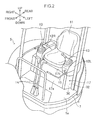
Fig. 2 is a perspective view of an operation space defined in the hydraulic excavator; -
Fig. 3 is a perspective view showing the internal structure of an upturn type of console box provided in the hydraulic excavator and the structure around the console box; -
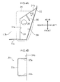
Fig. 4A is a plan view showing a part of a seat stand provided in the hydraulic excavator, the part defining a hose accommodation space; -
Fig. 4B is a view showing a guide member provided in the hydraulic excavator as viewed along an arrow IXB ofFig. 4A ; -
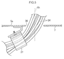
Fig. 5 is a partial cross-sectional side view showing a clamp fixed to a flooring under the operation space and a hydraulic hose held by the clamp; -
Fig. 6A is a side view of showing the console box at a fall-down position; -
Fig. 6B is a side view showing the console box at an upturn position; and - Each of
Figs. 7A and 7B is a perspective view showing a modification of a guide member. - Below will be specifically described an embodiment of the present invention based on the drawings. It should be noted that the following description is just exemplary in nature and not intended to limit the present invention, its application, or its use.
-
Fig. 1 shows a hydraulic excavator 1 as an example of a working machine according to the present invention. The hydraulic excavator 1 according to this embodiment is a small-sized working machine having a machine mass of 5t or less, namely, a so-called compact excavator. The hydraulic excavator 1 includes abase carrier 2 having a pair of crawlers which allows thebase carrier 2 to make flexible travelling, and amachine body 3 mounted on thebase carrier 2 so as to be slewable. Themachine body 3 includes an attachment 4, anoperation space 5, aflooring 7, and adevice room 6. The attachment 4 is at the front part of themachine body 3, and thedevice room 6 is at the rear part of themachine body 3. Theoperation space 5 is located forward of thedevice room 6 and at substantially the center of themachine body 3. Theflooring 7 in the embodiment is formed of a horizontal plate member and located below theoperation space 5, having an upper surface forming afloor surface 5a of theoperation space 5. - Note that directions such as up, down, left, and right in the following description are determined with respect to the
machine body 3, as indicated by respective arrows in each drawing. - The attachment 4 is a working device configured to perform a working movement according to an operation by an operator. The attachment 4 includes a boom, an arm, and a bucket, respective movements thereof being hydraulically controlled. The attachment 4 according to the embodiment is supported by a
swing bracket 4a and allowed to be swung integrally with theswing bracket 4a in right and left directions relatively to the other parts of themachine body 3. - The
device room 6 accommodates various hydraulic devices for hydraulic control of the attachment 4 and an engine, which are not shown in the drawing. In theoperation space 5, the operator is allowed to perform the operation on the attachment 4 and the control of the hydraulic excavator 1. In the embodiment, theoperation space 5 is opened to the surroundings thereof, wherein an entrance is formed on the left side of theoperation space 5. -
Fig. 2 shows a plurality of components installed in theoperation space 5. The hydraulic excavator further includes, as respective components, an operator'sseat 11, right andleft console boxes seat 11, a pair oftravelling levers 14, and aseat stand 17. - The
floor surface 5a formed by theflooring 7 is spread under the front part of theoperation space 5, and theseat stand 17 is provided in the rear part of theoperation space 5. - The
seat stand 17 includes afront wall portion 17a, asupport wall portion 17b, and aside wall portion 31. Thefront wall portion 17a stands upright on theflooring 7 and is spread in the right and left directions, i.e., in a width direction, to face the front side. Thesupport wall portion 17b extends rearward from the upper end of thefront wall portion 17a and supports the operator'sseat 11 and the right andleft console boxes support wall portion 17b. The operator'sseat 11 and the right andleft console boxes support wall portion 17b higher than thefloor surface 5a, so as to allow the operator to easily perform seating in the operator'sseat 11 and manipulating theconsole boxes - Each of the right and
left console boxes console boxes left console box 12L in the embodiment, is a so-called upturn type of console box. As shown inFig. 3 , theleft console box 12L includes anoperation lever 13, apilot valve 21 which is a device for hydraulic control, aframe structure 22, anupturn lever 15, and aconsole cover 23. - The
console cover 23 is shaped as a box, disposed around thepilot valve 21 and theframe structure 22 to cover them. Theoperation lever 13 is installed to theconsole cover 23 while being coupled to thepilot valve 21. - The
frame structure 22 has a rear end part supported by theseat stand 17. Specifically, thesupport wall portion 17b of theseat stand 17a is attached with abracket 25, which supports the rear end part of theframe structure 22 so as to allow theframe structure 22 to be turned about a lateral axis J extending in the right and left directions. Theupturn lever 15 is attached to the left side part of theframe structure 22, having a front part which greatly protrudes forward beyond theconsole cover 23. Thepilot valve 21 has a substantially cylindrical shape and is attached to the upper part of the front end of theframe structure 22 in a forward leaning posture. - The
frame structure 22, thepilot valve 21, theoperation lever 13, theupturn lever 15, and theconsole cover 23 described above are able to be integrally upturned. Specifically, theleft console box 12L is able to be turned between a fall-down position at which theupturn lever 15 blocks the entrance route as shown inFigs. 2 ,3 , and6A and an upturn position at which theleft console box 12L is raised so as to direct the front part thereof upward (including obliquely upward) to open the entrance route as shown inFig. 6B : the operator can move theconsole box 12L from the fall-down position to the upturn position, that is, can upturn theconsole box 12L, by performing an upturn operation which is an operation of lifting up theupturn lever 15 of theleft console box 12L at the fall-down position to turn theupturn lever 15 rearward. Theleft console box 12L thus upturned to the upturn position opens the entrance route to thereby allow an operator to get in and get out of theoperation space 5 easily. - This hydraulic excavator further includes a group of hydraulic hoses constituted of a plurality of
hydraulic hoses 24. The group of hydraulic hoses includes an over-floor region, which is routed so as to interconnect the hydraulic control device in thedevice room 6 and thepilot valve 21. The over-floor region extends upward from thefloor surface 5a to be connected to the lower end part of thepilot valve 21 in the forward leaning posture in the front part of theleft console box 12L at the fall-down position as shown inFig. 6A . - The group of hydraulic hoses is attached with a
protective cover 27, which bundles the plurality ofhoses 24 included in the group of hydraulic hoses. A specific part of the group of hydraulic hoses, to which part theprotective cover 27 is attached, includes acurved portion 24a which is deflected rearward to be curved when theleft console box 12L is at the fall-down position as shown inFig. 6A . Since the group of hydraulic hoses is pulled upward when theleft console box 12L is at the upturn position, thecurved portion 24a is curved more significantly, i.e., with a greater curvature, when theleft console box 12L is at the fall-down position than that when theleft console box 12L is at the upturn position. - The seat stand 17 defines an
accommodation space 30 which is a hose accommodation space for accommodating the over-floor region of the group of hydraulic hoses so as to conceal the over-floor region from the outside. As shown inFig. 4A , theaccommodation space 30 is an oblong tubular space positioned below theleft console box 12L and having a shape vertically long with a narrow breadth in the right and left directions. Theaccommodation space 30 is formed by notching the front part of the left end of theseat stand 17, specifically notching the part of the left end of thefront wall portion 17a and the left front part of thesupport wall portion 17b of theseat stand 17. - The
side wall portion 31 of the seat stand 17 defines the right end of theaccommodation space 30, i.e., the inner end thereof in the right and left directions. Besides, the hydraulic excavator further includes aside cover 32 detachably attached to theseat stand 17, theside cover 32 defining the left end of theaccommodation space 30, i.e., the outer end thereof in the right and left directions. The upper part of theaccommodation space 30 is closed with theleft console box 12L. The lower end of theaccommodation space 30 is defined by thefloor surface 5a formed by theflooring 7. - The
side wall portion 31 is formed of a vertical plate member, being interposed between theflooring 7 and thesupport wall portion 17b. Theside wall portion 31 includes a firstside wall portion 31a and a secondside wall portion 31b integrally. The firstside wall portion 31a extends rearward from the left end of thefront wall portion 17a to face the left side, i.e., the outer side in the right and left directions. The secondside wall portion 31b extends from the rear end of the firstside wall portion 31 a obliquely so as to be displaced rearward with approach to the outer side in the right and left directions (the left side in the embodiment). The outer surface of the secondside wall portion 31b, i.e., the surface facing theaccommodation space 30, corresponds to an oblique guide surface which is laterally oblique relatively to a plane orthogonal to an axis of the turning of theleft console box 12L, i.e., the lateral axis J, and guides thecurved portion 24a as will be described later. - The hydraulic excavator further includes a
guide member 35 for guiding and supporting thecurved portion 24a. Theguide member 35 is arch-shaped and attached to the secondside wall portion 31 b to thereby define a reception space for receiving thecurved portion 24a between the secondside wall portion 31b and theguide member 35. - Specifically, as shown in
Fig. 4B , theguide member 35 integrally has a pair of upper andlower column portions vertical column portion 35c. The upper andlower column portions side wall portion 31 b so as to protrude outward (toward the accommodation-space side) from the secondside wall portion 31b. Thevertical column portion 35c interconnects respective outer ends of the upper andlower column portions lower column portions guide member 35 can be manufactured, for example, by bending. - The
guide member 35 is disposed at a position which allows theguide member 35 to receive thecurved portion 24a of the group of hydraulic hoses inside the frame formed by the upper andlower column portions vertical column portion 35c. Specifically, the upper andlower column portions side wall portion 31b so as to be vertically aligned. More specifically, theguide member 35 is disposed so as to locate thelower column portion 35b under the peak part of thecurved portion 24a, i.e., the most rearward positioned part of thecurved portion 24a, and so as to locate theupper column portion 35a over the top part thereof. - The
flooring 7 defining the lower end of theaccommodation space 30 is formed with aninsertion hole 36 providing communication of the upper and lower sides of theflooring 7 with each other, and the group of hydraulic hoses is inserted into theinsertion hole 36 to pass through theflooring 7. In order to connect the hydraulic equipment accommodated in thedevice room 6 and thepilot valve 21 to each other, the group of hydraulic hoses includes an under-floor region to be routed under theflooring 7, in addition to the over-floor region. The over-floor region is drawn out over theflooring 7 from the under-floor region through theinsertion hole 36. - The hydraulic excavator further includes a
clamp 37 shown inFig. 5 . Theclamp 37 is fixed to a part of the lower surface of theflooring 7 in the vicinity of theinsertion hole 36 to hold the group of hydraulic hoses so as to grip it. Specifically, the group of hydraulic hoses is supported by theclamp 37 in an oblique state relative to an axis Xh of theinsertion hole 36 so as to lean rearward the over-floor region of the group of hydraulic hoses, i.e., the region thereof drawn out upward from theinsertion hole 36. - In the hydraulic excavator, the outer surface of the second
side wall portion 31 b of theside wall portion 31 in the seat stand 17 functions as the oblique guide surface for protecting the group of hydraulic hoses, particularly thecurved portion 24a. In the small-sized hydraulic excavator shown here, thedevice room 6 is positioned immediately rearward of theoperation space 5 to compress the rear part of theaccommodation space 30 due to the arrangement of equipment. This makes it difficult to avoid the contact of thecurved portion 24a and theside wall portion 31 with each other when theleft console box 12L is shifted to the fall-down position to significantly curve the group of hydraulic hoses. Furthermore, the contact can exert excessive force on the group of hydraulic hoses to thereby bring it into abnormal deformation or reduce durability thereof. For effective reduction in such a burden of the group of hydraulic hoses, the oblique guide surface formed by the outer surface of the secondside wall portion 31b, that is, the surface being oblique so as to be displaced rearward with approach to the outer side in the right and left directions, i.e., the left side in the embodiment, plays a role of shifting thecurved portion 24a laterally. - More specifically, although the rearward curvature of the
curved portion 24a, which is a vertically middle part of the group of hydraulic hoses, is increased with the turning of theleft console box 12L from the upturn position to the fall-down position to thereby bring thecurved portion 24a into contact with the outer surface of the secondside wall portion 31b, the outer surface, being oblique so as to be displaced rearward with approach to the outer side in the right and left directions, can guide thecurved portion 24a so as to make thecurved portion 24a slide laterally along the outer surface by the turning of theconsole box 12L, that is, can shift the middle portion of the group of hydraulic hoses laterally leftward so as to allow thecurved portion 24a slide laterally while keeping vertically curved. This guide effectively reduces the burden due to the contact of the group of hydraulic hoses with theside wall portion 31 while hardly hindering the group of hydraulic hoses from curving movement. - In addition, the
guide member 35 assists the group of hydraulic hoses in the smooth movement. Specifically, theguide member 35 receives thecurved portion 24a of the group of hydraulic hoses sliding along the outer surface of the secondside wall portion 31b, into the reception space between theguide member 35 and the outer surface of the secondside wall portion 31b, to guide thecurved portion 24a while supporting it, thereby suppressing flapping of the group of hydraulic hoses to stabilize the sliding movement thereof. - Besides, the
clamp 37 also contributes to the stable sliding movement of the group of hydraulic hoses. Specifically, theclamp 37, holding the under-floor region of the group of hydraulic hoses so as to lean the over-floor region of the group of hydraulic hoses rearward, can direct the curvature of the group of hydraulic hoses rearward to thereby enable thecurved portion 24a of the over-floor region to come into stable contact with the secondside wall portion 31b. Furthermore, theclamp 37 makes the under-floor region extend obliquely downward from theinsertion hole 36 of theflooring 7 to thereby decrease the protrusion of the under-floor region beyond theflooring 7, which eliminates necessity for excessively curving the group of hydraulic hoses. This facilitates routing of the group of hydraulic hoses along theflooring 7 under the floor. - The working machine according to the present invention is not limited to the above-described embodiment but permitted to include other various modes, e.g., the following modes.
- The guide member according to the present invention may also be semicircular. The shape of the guide member only has to be a shape capable of guiding the curved portion of the group of hydraulic hoses while supporting it, hence not limited to the shape of the arch. Specifically, as the guide member, may be used a guide member having a shape similar to the
guide member 35A shown inFig. 7A wherein theupper column portion 35a thereof is omitted while only thelower column portion 35b and thevertical column portion 35c extending upward from the outer end thereof remains, that is, an L-shaped member having an opened upper end. Alternatively, there may also be used aguide member 35B shown inFig. 7B , which protrudes from the secondside wall portion 31b while being curved upward to have an opened upper end. Although not shown in the drawing, only a straight bar capable of receiving the lower part of the group of hydraulic hoses is also permitted to constitute the guide member. Moreover, the guide member is not limited to the bar but permitted to be a plate member or resin molded products having other shapes. - The oblique guide surface is not limited to a flat surface but permitted to be a curved surface. The specific obliqueness of the oblique guide surface can be appropriately determined in accordance with specifications. The number of
hydraulic hoses 24 is also free from limitation. - The console box as the essential element of the present invention is not limited to the
left console box 12L. In the case of locating the entrance on the right side, theright console box 12R corresponds to the element of the present invention. In addition, the working machine according to the present invention may also be one including only a single console box. The present invention is, thus, permitted to be applied to a working machine including at least one console box capable of being turned so as to open and close the entrance. - As described above, according to the present invention, there is provided a working machine including a so-called upturn type of console box and a hydraulic hose connected to the console box, the working machine being capable of effectively preventing excessive force from being exerted on the hydraulic hose involved by the movement of the console box, within a space limitation. The provided working machine comprises: a base carrier; a machine body mounted on the base carrier, the machine body including a working device configured to make a working movement according to an operation, a device room accommodating a device for hydraulic control of the working device, a flooring forming a floor surface, and an operation space defined on the floor surface to allow the operation on the working device to be performed in the operation space; a seat stand provided in the operation space and including a side wall portion defining a hose accommodation space; an operator's seat supported by the seat stand at a position higher than the floor surface; a console box supported by the seat stand at a position higher than the floor surface and alongside the operator's seat, the console box having a rear part coupled to the seat stand so as to be capable of being turned to allow the console box to be moved between a fall-down position at which the console box blocks an entrance route lateral to the operator's seat and an upturn position at which a front part of the console box is upturned so as to open the entrance route; and a hydraulic hose including an over-floor region which extends upward from the floor surface to be connected to the front part of the console box, the over-floor region of the hydraulic hose being accommodated in the hose accommodation space so as to be rearward curved with a curvature which is increased with a movement of the console box from the fall-down position to the upturn position. The side wall portion of the seat stand has an oblique guide surface which is laterally oblique relatively to a plane orthogonal to an axis of the turning of the console box, and the oblique guide surface guides a curved portion of the over-floor region of the hydraulic hose so as to make the curved portion slide laterally along the oblique guide surface by the turning of the console box.
- According to the working machine, the hydraulic hose extending upward from the flooring and connected to the console box is accommodated in the hose accommodation space provided in the seat stand, and the side wall portion defining the hose accommodation space provides the oblique guide surface capable of receiving the curved portion of the hydraulic hose and causing the curved portion thereof to slide laterally. The oblique guide surface, thus, can shift the curved portion, i.e., the portion of the hydraulic hose whose rearward curvature is increased with the movement of the console box from the upturn position to the fall-down position, so as to make the curved portion slide laterally, thereby allowing the burden of the hydraulic hose due to the contact with the side wall portion to be effectively reduced while hardly hindering the hydraulic hose from vertical curving movement.
- The working machine according to the present invention, preferably, further comprises a guide member protruding from the oblique guide surface and including a portion located under the curved portion sliding along the oblique guide surface to guide the curved portion while supporting the curved portion. The guide member can suppress flapping of the hydraulic hose sliding along the oblique guide surface to stabilize the movement of the hydraulic hose.
- The guide member is, preferably, shaped as, e.g., an arch defining a reception space to receive the curved portion of the hydraulic hose and supports the curved portion while allowing the curved portion received in the reception space to slide. The thus shaped guide member can support the curved portion of the hydraulic hose more stably, thereby further effectively suppressing the flapping of the hydraulic hose.
- In the case where the hydraulic hose includes an under-floor region routed under the flooring and between the device room and the operation space, in addition to the over-floor region drawn out over the flooring from the under-floor region through an insertion hole formed in the flooring, it is preferable that the working machine according to the present invention further includes a clamp which is fixed to the flooring in the vicinity of the insertion hole to hold the hydraulic hose so as to lean the over-floor region rearward. The clamp directs the curvature of the over-floor region rearward to thereby allow the curved portion of the over-floor region to make stable contact with the oblique guide surface and facilitate routing of the under-floor region.
- This application is based on Japanese Patent application No.
2013-225403 - Although the present invention has been fully described by way of example with reference to the accompanying drawings, it is to be understood that various changes and modifications will be apparent to those skilled in the art. Therefore, unless otherwise such changes and modifications depart from the scope of the present invention hereinafter defined, they should be construed as being included therein.
- Provided is a working machine including a console box (12L) and a hydraulic hose (24), being capable of preventing excessive force from being exerted on the hydraulic hose (24) by movement of the console box (12L). The working machine includes a machine body (3) including an operation space (5) on a floor surface (5a), a seat stand (17) in the operation space (5) and including a side wall portion (31) defining an accommodation space (30), an operator's seat (11), a console box (12L) capable of moving between a fall-down position and an upturn position, and a hydraulic hose (24) including an over-floor region extending upward from the floor surface (5a) to be connected to a front part of the console box (12L) and accommodated in the accommodation space (30) so as to have a curved portion (24a). The side wall portion (31) has an oblique guide surface, which guides the curved portion (24a) to make the curved portion (24a) slide along the oblique guide surface by turning of the console box (12L).
Claims (4)
- A working machine comprising:a base carrier;a machine body mounted on the base carrier, the machine body including a working device configured to make a working movement according to an operation, a device room accommodating a device for hydraulic control of the working device, a flooring forming a floor surface, and an operation space defined on the floor surface to allow the operation on the working device to be performed in the operation space;a seat stand provided in the operation space and including a side wall portion defining a hose accommodation space;an operator's seat supported by the seat stand at a position higher than the floor surface;a console box supported by the seat stand at a position higher than the floor surface and alongside the operator's seat, the console box having a rear part coupled to the seat stand so as to be capable of being turned to allow the console box to be moved between a fall-down position at which the console box blocks an entrance route lateral to the operator's seat and an upturn position at which a front part of the console box is upturned so as to open the entrance route; anda hydraulic hose including an over-floor region which extends upward from the floor surface to be connected to the front part of the console box, the over-floor region being accommodated in the hose accommodation space so as to be rearward curved with a curvature which is increased with a movement of the console box from the fall-down position to the upturn position, wherein:the side wall portion of the seat stand has an oblique guide surface which is laterally oblique relatively to a plane orthogonal to an axis of the turning of the console box; andthe oblique guide surface guides a curved portion of the over-floor region of the hydraulic hose so as to make the curved portion slide laterally along the oblique guide surface by the turning of the console box.
- The working machine according to claim 1, further comprising a guide member protruding from the oblique guide surface and including a portion located under the curved portion sliding along the oblique guide surface to guide the curved portion while supporting the curved portion.
- The working machine according to claim 2, wherein the guide member is shaped as an arch defining a reception space to receive the curved portion of the hydraulic hose and supports the curved portion while allowing the curved portion received in the reception space to slide.
- The working machine according to any one of claims 1 to 3, further comprising a clamp for holding the hydraulic hose, wherein: the hydraulic hose includes an under-floor region routed under the flooring and between the device room and the operation space, in addition to the over-floor region; the over-floor region is drawn out over the flooring from the under-floor region through an insertion hole formed in the flooring; and the clamp is fixed to the flooring in the vicinity of the insertion hole to hold the hydraulic hose so as to lean the over-floor region rearward.
Applications Claiming Priority (1)
| Application Number | Priority Date | Filing Date | Title |
|---|---|---|---|
| JP2013225403A JP5850022B2 (en) | 2013-10-30 | 2013-10-30 | Work machine |
Publications (2)
| Publication Number | Publication Date |
|---|---|
| EP2868809A1 true EP2868809A1 (en) | 2015-05-06 |
| EP2868809B1 EP2868809B1 (en) | 2018-06-20 |
Family
ID=51661879
Family Applications (1)
| Application Number | Title | Priority Date | Filing Date |
|---|---|---|---|
| EP14186519.6A Not-in-force EP2868809B1 (en) | 2013-10-30 | 2014-09-26 | Working machine with a console box |
Country Status (5)
| Country | Link |
|---|---|
| US (1) | US9206585B2 (en) |
| EP (1) | EP2868809B1 (en) |
| JP (1) | JP5850022B2 (en) |
| KR (1) | KR102166893B1 (en) |
| CN (1) | CN104594435B (en) |
Families Citing this family (8)
| Publication number | Priority date | Publication date | Assignee | Title |
|---|---|---|---|---|
| JP5803984B2 (en) * | 2013-06-13 | 2015-11-04 | コベルコ建機株式会社 | Work machine |
| JP5850021B2 (en) * | 2013-10-30 | 2016-02-03 | コベルコ建機株式会社 | Construction machine routing structure |
| JP6213519B2 (en) * | 2015-05-18 | 2017-10-18 | コベルコ建機株式会社 | Work machine |
| JP6559612B2 (en) * | 2016-05-19 | 2019-08-14 | 株式会社クボタ | Cable wiring structure, operation device and work machine |
| US9745719B1 (en) * | 2016-02-29 | 2017-08-29 | Deere & Company | Mechanical control arrangement for work vehicle |
| JP6794207B2 (en) * | 2016-10-03 | 2020-12-02 | 株式会社クボタ | Work machine |
| EP3190236B1 (en) * | 2016-10-21 | 2019-09-18 | Komatsu, Ltd. | Work vehicle with control console |
| JP7016774B2 (en) * | 2018-06-19 | 2022-02-07 | ヤンマーパワーテクノロジー株式会社 | Installation structure of electrical components and hydraulic hoses of work machines |
Citations (3)
| Publication number | Priority date | Publication date | Assignee | Title |
|---|---|---|---|---|
| EP1074665A1 (en) * | 1999-08-03 | 2001-02-07 | Kobelco Construction Machinery Co., Ltd. | Control device for a construction machine |
| JP2010090589A (en) * | 2008-10-07 | 2010-04-22 | Hitachi Constr Mach Co Ltd | Construction machinery |
| JP2012092611A (en) | 2010-10-28 | 2012-05-17 | Kobelco Contstruction Machinery Ltd | Hose coating structure and hose cover for construction machine |
Family Cites Families (6)
| Publication number | Priority date | Publication date | Assignee | Title |
|---|---|---|---|---|
| US6352133B1 (en) * | 1999-04-21 | 2002-03-05 | Hitachi Construction Machinery Co., Ltd. | Construction machinery |
| JP4085675B2 (en) * | 2002-04-01 | 2008-05-14 | 株式会社豊田自動織機 | Industrial vehicle |
| JP4162233B2 (en) * | 2003-11-07 | 2008-10-08 | 新キャタピラー三菱株式会社 | Support structure for insertion member in construction machinery |
| US7290635B2 (en) * | 2004-07-02 | 2007-11-06 | Caterpillar Inc. | Work machine operator control station with moveably attached controller |
| JP4648962B2 (en) * | 2008-03-27 | 2011-03-09 | 株式会社クボタ | Working unit structure |
| JP4988661B2 (en) * | 2008-07-18 | 2012-08-01 | 日立建機株式会社 | Construction machinery |
-
2013
- 2013-10-30 JP JP2013225403A patent/JP5850022B2/en active Active
-
2014
- 2014-09-19 US US14/491,031 patent/US9206585B2/en active Active
- 2014-09-26 EP EP14186519.6A patent/EP2868809B1/en not_active Not-in-force
- 2014-09-30 CN CN201410516522.7A patent/CN104594435B/en not_active Expired - Fee Related
- 2014-10-17 KR KR1020140140537A patent/KR102166893B1/en not_active Expired - Fee Related
Patent Citations (3)
| Publication number | Priority date | Publication date | Assignee | Title |
|---|---|---|---|---|
| EP1074665A1 (en) * | 1999-08-03 | 2001-02-07 | Kobelco Construction Machinery Co., Ltd. | Control device for a construction machine |
| JP2010090589A (en) * | 2008-10-07 | 2010-04-22 | Hitachi Constr Mach Co Ltd | Construction machinery |
| JP2012092611A (en) | 2010-10-28 | 2012-05-17 | Kobelco Contstruction Machinery Ltd | Hose coating structure and hose cover for construction machine |
Also Published As
| Publication number | Publication date |
|---|---|
| US9206585B2 (en) | 2015-12-08 |
| CN104594435A (en) | 2015-05-06 |
| KR20150050374A (en) | 2015-05-08 |
| JP5850022B2 (en) | 2016-02-03 |
| EP2868809B1 (en) | 2018-06-20 |
| KR102166893B1 (en) | 2020-10-16 |
| JP2015086577A (en) | 2015-05-07 |
| CN104594435B (en) | 2018-01-05 |
| US20150115659A1 (en) | 2015-04-30 |
Similar Documents
| Publication | Publication Date | Title |
|---|---|---|
| EP2868809B1 (en) | Working machine with a console box | |
| US10190284B2 (en) | Boom for a working machine with a partition inside the boom | |
| US8414051B2 (en) | Electrical component housing device and construction machine incorporated with the same | |
| KR102178694B1 (en) | Seat stand and working machine having the same | |
| US20120195727A1 (en) | Work Vehicle | |
| US10030365B2 (en) | Valve arrangement structure of construction machine | |
| WO2020021893A1 (en) | Cab of construction machine | |
| JP2005335429A (en) | Armrest device | |
| EP2253763A1 (en) | Construction machine | |
| US20130256468A1 (en) | Device for fixing hydraulic pipe of boom swing type excavator | |
| EP2899102A2 (en) | Construction machine | |
| CN107128258B (en) | Machine control device for work vehicle | |
| EP2813624B1 (en) | Cable and hose support and guide for construction machine | |
| JP6095316B2 (en) | Brake hose support structure for motorcycles | |
| KR20190108124A (en) | Work vehicle | |
| US10315534B2 (en) | Work vehicle | |
| JP6213519B2 (en) | Work machine | |
| JP6229685B2 (en) | Construction machine routing structure | |
| JP5843724B2 (en) | Loader working machine | |
| JP6891912B2 (en) | Transplant machine | |
| CN208462418U (en) | Harvester | |
| JP6210098B2 (en) | Work machine | |
| JP5805595B2 (en) | Work machine | |
| JP2005255002A (en) | Mounting device for harness | |
| JP2000170206A (en) | Hydraulic piping protection mounting structure for offset boom excavator |
Legal Events
| Date | Code | Title | Description |
|---|---|---|---|
| PUAI | Public reference made under article 153(3) epc to a published international application that has entered the european phase |
Free format text: ORIGINAL CODE: 0009012 |
|
| 17P | Request for examination filed |
Effective date: 20140926 |
|
| AK | Designated contracting states |
Kind code of ref document: A1 Designated state(s): AL AT BE BG CH CY CZ DE DK EE ES FI FR GB GR HR HU IE IS IT LI LT LU LV MC MK MT NL NO PL PT RO RS SE SI SK SM TR |
|
| AX | Request for extension of the european patent |
Extension state: BA ME |
|
| R17P | Request for examination filed (corrected) |
Effective date: 20150811 |
|
| RBV | Designated contracting states (corrected) |
Designated state(s): AL AT BE BG CH CY CZ DE DK EE ES FI FR GB GR HR HU IE IS IT LI LT LU LV MC MK MT NL NO PL PT RO RS SE SI SK SM TR |
|
| GRAP | Despatch of communication of intention to grant a patent |
Free format text: ORIGINAL CODE: EPIDOSNIGR1 |
|
| RIC1 | Information provided on ipc code assigned before grant |
Ipc: E02F 9/22 20060101ALI20171212BHEP Ipc: E02F 9/16 20060101ALI20171212BHEP Ipc: E02F 3/32 20060101AFI20171212BHEP |
|
| INTG | Intention to grant announced |
Effective date: 20180116 |
|
| GRAS | Grant fee paid |
Free format text: ORIGINAL CODE: EPIDOSNIGR3 |
|
| GRAA | (expected) grant |
Free format text: ORIGINAL CODE: 0009210 |
|
| AK | Designated contracting states |
Kind code of ref document: B1 Designated state(s): AL AT BE BG CH CY CZ DE DK EE ES FI FR GB GR HR HU IE IS IT LI LT LU LV MC MK MT NL NO PL PT RO RS SE SI SK SM TR |
|
| REG | Reference to a national code |
Ref country code: GB Ref legal event code: FG4D |
|
| REG | Reference to a national code |
Ref country code: IE Ref legal event code: FG4D |
|
| REG | Reference to a national code |
Ref country code: AT Ref legal event code: REF Ref document number: 1010699 Country of ref document: AT Kind code of ref document: T Effective date: 20180715 |
|
| REG | Reference to a national code |
Ref country code: DE Ref legal event code: R096 Ref document number: 602014027244 Country of ref document: DE |
|
| REG | Reference to a national code |
Ref country code: FR Ref legal event code: PLFP Year of fee payment: 5 |
|
| REG | Reference to a national code |
Ref country code: NL Ref legal event code: MP Effective date: 20180620 |
|
| PG25 | Lapsed in a contracting state [announced via postgrant information from national office to epo] |
Ref country code: FI Free format text: LAPSE BECAUSE OF FAILURE TO SUBMIT A TRANSLATION OF THE DESCRIPTION OR TO PAY THE FEE WITHIN THE PRESCRIBED TIME-LIMIT Effective date: 20180620 Ref country code: BG Free format text: LAPSE BECAUSE OF FAILURE TO SUBMIT A TRANSLATION OF THE DESCRIPTION OR TO PAY THE FEE WITHIN THE PRESCRIBED TIME-LIMIT Effective date: 20180920 Ref country code: NO Free format text: LAPSE BECAUSE OF FAILURE TO SUBMIT A TRANSLATION OF THE DESCRIPTION OR TO PAY THE FEE WITHIN THE PRESCRIBED TIME-LIMIT Effective date: 20180920 Ref country code: SE Free format text: LAPSE BECAUSE OF FAILURE TO SUBMIT A TRANSLATION OF THE DESCRIPTION OR TO PAY THE FEE WITHIN THE PRESCRIBED TIME-LIMIT Effective date: 20180620 Ref country code: LT Free format text: LAPSE BECAUSE OF FAILURE TO SUBMIT A TRANSLATION OF THE DESCRIPTION OR TO PAY THE FEE WITHIN THE PRESCRIBED TIME-LIMIT Effective date: 20180620 |
|
| REG | Reference to a national code |
Ref country code: LT Ref legal event code: MG4D |
|
| PG25 | Lapsed in a contracting state [announced via postgrant information from national office to epo] |
Ref country code: LV Free format text: LAPSE BECAUSE OF FAILURE TO SUBMIT A TRANSLATION OF THE DESCRIPTION OR TO PAY THE FEE WITHIN THE PRESCRIBED TIME-LIMIT Effective date: 20180620 Ref country code: HR Free format text: LAPSE BECAUSE OF FAILURE TO SUBMIT A TRANSLATION OF THE DESCRIPTION OR TO PAY THE FEE WITHIN THE PRESCRIBED TIME-LIMIT Effective date: 20180620 Ref country code: GR Free format text: LAPSE BECAUSE OF FAILURE TO SUBMIT A TRANSLATION OF THE DESCRIPTION OR TO PAY THE FEE WITHIN THE PRESCRIBED TIME-LIMIT Effective date: 20180921 Ref country code: RS Free format text: LAPSE BECAUSE OF FAILURE TO SUBMIT A TRANSLATION OF THE DESCRIPTION OR TO PAY THE FEE WITHIN THE PRESCRIBED TIME-LIMIT Effective date: 20180620 |
|
| REG | Reference to a national code |
Ref country code: AT Ref legal event code: MK05 Ref document number: 1010699 Country of ref document: AT Kind code of ref document: T Effective date: 20180620 |
|
| PG25 | Lapsed in a contracting state [announced via postgrant information from national office to epo] |
Ref country code: NL Free format text: LAPSE BECAUSE OF FAILURE TO SUBMIT A TRANSLATION OF THE DESCRIPTION OR TO PAY THE FEE WITHIN THE PRESCRIBED TIME-LIMIT Effective date: 20180620 |
|
| PG25 | Lapsed in a contracting state [announced via postgrant information from national office to epo] |
Ref country code: IS Free format text: LAPSE BECAUSE OF FAILURE TO SUBMIT A TRANSLATION OF THE DESCRIPTION OR TO PAY THE FEE WITHIN THE PRESCRIBED TIME-LIMIT Effective date: 20181020 Ref country code: PL Free format text: LAPSE BECAUSE OF FAILURE TO SUBMIT A TRANSLATION OF THE DESCRIPTION OR TO PAY THE FEE WITHIN THE PRESCRIBED TIME-LIMIT Effective date: 20180620 Ref country code: EE Free format text: LAPSE BECAUSE OF FAILURE TO SUBMIT A TRANSLATION OF THE DESCRIPTION OR TO PAY THE FEE WITHIN THE PRESCRIBED TIME-LIMIT Effective date: 20180620 Ref country code: AT Free format text: LAPSE BECAUSE OF FAILURE TO SUBMIT A TRANSLATION OF THE DESCRIPTION OR TO PAY THE FEE WITHIN THE PRESCRIBED TIME-LIMIT Effective date: 20180620 Ref country code: CZ Free format text: LAPSE BECAUSE OF FAILURE TO SUBMIT A TRANSLATION OF THE DESCRIPTION OR TO PAY THE FEE WITHIN THE PRESCRIBED TIME-LIMIT Effective date: 20180620 Ref country code: RO Free format text: LAPSE BECAUSE OF FAILURE TO SUBMIT A TRANSLATION OF THE DESCRIPTION OR TO PAY THE FEE WITHIN THE PRESCRIBED TIME-LIMIT Effective date: 20180620 Ref country code: SK Free format text: LAPSE BECAUSE OF FAILURE TO SUBMIT A TRANSLATION OF THE DESCRIPTION OR TO PAY THE FEE WITHIN THE PRESCRIBED TIME-LIMIT Effective date: 20180620 |
|
| PG25 | Lapsed in a contracting state [announced via postgrant information from national office to epo] |
Ref country code: SM Free format text: LAPSE BECAUSE OF FAILURE TO SUBMIT A TRANSLATION OF THE DESCRIPTION OR TO PAY THE FEE WITHIN THE PRESCRIBED TIME-LIMIT Effective date: 20180620 Ref country code: ES Free format text: LAPSE BECAUSE OF FAILURE TO SUBMIT A TRANSLATION OF THE DESCRIPTION OR TO PAY THE FEE WITHIN THE PRESCRIBED TIME-LIMIT Effective date: 20180620 |
|
| REG | Reference to a national code |
Ref country code: DE Ref legal event code: R097 Ref document number: 602014027244 Country of ref document: DE |
|
| PLBE | No opposition filed within time limit |
Free format text: ORIGINAL CODE: 0009261 |
|
| STAA | Information on the status of an ep patent application or granted ep patent |
Free format text: STATUS: NO OPPOSITION FILED WITHIN TIME LIMIT |
|
| PG25 | Lapsed in a contracting state [announced via postgrant information from national office to epo] |
Ref country code: MC Free format text: LAPSE BECAUSE OF FAILURE TO SUBMIT A TRANSLATION OF THE DESCRIPTION OR TO PAY THE FEE WITHIN THE PRESCRIBED TIME-LIMIT Effective date: 20180620 |
|
| REG | Reference to a national code |
Ref country code: CH Ref legal event code: PL |
|
| 26N | No opposition filed |
Effective date: 20190321 |
|
| PG25 | Lapsed in a contracting state [announced via postgrant information from national office to epo] |
Ref country code: DK Free format text: LAPSE BECAUSE OF FAILURE TO SUBMIT A TRANSLATION OF THE DESCRIPTION OR TO PAY THE FEE WITHIN THE PRESCRIBED TIME-LIMIT Effective date: 20180620 |
|
| REG | Reference to a national code |
Ref country code: BE Ref legal event code: MM Effective date: 20180930 |
|
| REG | Reference to a national code |
Ref country code: IE Ref legal event code: MM4A |
|
| PG25 | Lapsed in a contracting state [announced via postgrant information from national office to epo] |
Ref country code: LU Free format text: LAPSE BECAUSE OF NON-PAYMENT OF DUE FEES Effective date: 20180926 |
|
| PG25 | Lapsed in a contracting state [announced via postgrant information from national office to epo] |
Ref country code: IE Free format text: LAPSE BECAUSE OF NON-PAYMENT OF DUE FEES Effective date: 20180926 |
|
| PG25 | Lapsed in a contracting state [announced via postgrant information from national office to epo] |
Ref country code: BE Free format text: LAPSE BECAUSE OF NON-PAYMENT OF DUE FEES Effective date: 20180930 Ref country code: CH Free format text: LAPSE BECAUSE OF NON-PAYMENT OF DUE FEES Effective date: 20180930 Ref country code: LI Free format text: LAPSE BECAUSE OF NON-PAYMENT OF DUE FEES Effective date: 20180930 Ref country code: SI Free format text: LAPSE BECAUSE OF FAILURE TO SUBMIT A TRANSLATION OF THE DESCRIPTION OR TO PAY THE FEE WITHIN THE PRESCRIBED TIME-LIMIT Effective date: 20180620 |
|
| PG25 | Lapsed in a contracting state [announced via postgrant information from national office to epo] |
Ref country code: AL Free format text: LAPSE BECAUSE OF FAILURE TO SUBMIT A TRANSLATION OF THE DESCRIPTION OR TO PAY THE FEE WITHIN THE PRESCRIBED TIME-LIMIT Effective date: 20180620 |
|
| PG25 | Lapsed in a contracting state [announced via postgrant information from national office to epo] |
Ref country code: MT Free format text: LAPSE BECAUSE OF NON-PAYMENT OF DUE FEES Effective date: 20180926 |
|
| PG25 | Lapsed in a contracting state [announced via postgrant information from national office to epo] |
Ref country code: TR Free format text: LAPSE BECAUSE OF FAILURE TO SUBMIT A TRANSLATION OF THE DESCRIPTION OR TO PAY THE FEE WITHIN THE PRESCRIBED TIME-LIMIT Effective date: 20180620 |
|
| PG25 | Lapsed in a contracting state [announced via postgrant information from national office to epo] |
Ref country code: PT Free format text: LAPSE BECAUSE OF FAILURE TO SUBMIT A TRANSLATION OF THE DESCRIPTION OR TO PAY THE FEE WITHIN THE PRESCRIBED TIME-LIMIT Effective date: 20180620 Ref country code: HU Free format text: LAPSE BECAUSE OF FAILURE TO SUBMIT A TRANSLATION OF THE DESCRIPTION OR TO PAY THE FEE WITHIN THE PRESCRIBED TIME-LIMIT; INVALID AB INITIO Effective date: 20140926 |
|
| PG25 | Lapsed in a contracting state [announced via postgrant information from national office to epo] |
Ref country code: MK Free format text: LAPSE BECAUSE OF NON-PAYMENT OF DUE FEES Effective date: 20180620 Ref country code: CY Free format text: LAPSE BECAUSE OF FAILURE TO SUBMIT A TRANSLATION OF THE DESCRIPTION OR TO PAY THE FEE WITHIN THE PRESCRIBED TIME-LIMIT Effective date: 20180620 |
|
| PGFP | Annual fee paid to national office [announced via postgrant information from national office to epo] |
Ref country code: DE Payment date: 20200916 Year of fee payment: 7 Ref country code: FR Payment date: 20200812 Year of fee payment: 7 Ref country code: GB Payment date: 20200916 Year of fee payment: 7 |
|
| PGFP | Annual fee paid to national office [announced via postgrant information from national office to epo] |
Ref country code: IT Payment date: 20200812 Year of fee payment: 7 |
|
| REG | Reference to a national code |
Ref country code: DE Ref legal event code: R119 Ref document number: 602014027244 Country of ref document: DE |
|
| GBPC | Gb: european patent ceased through non-payment of renewal fee |
Effective date: 20210926 |
|
| PG25 | Lapsed in a contracting state [announced via postgrant information from national office to epo] |
Ref country code: GB Free format text: LAPSE BECAUSE OF NON-PAYMENT OF DUE FEES Effective date: 20210926 Ref country code: FR Free format text: LAPSE BECAUSE OF NON-PAYMENT OF DUE FEES Effective date: 20210930 Ref country code: DE Free format text: LAPSE BECAUSE OF NON-PAYMENT OF DUE FEES Effective date: 20220401 |
|
| PG25 | Lapsed in a contracting state [announced via postgrant information from national office to epo] |
Ref country code: IT Free format text: LAPSE BECAUSE OF NON-PAYMENT OF DUE FEES Effective date: 20210926 |