EP2868617A1 - Damping arrangement for damping the opening noise of a machinery brake of an elevator hoisting machine; an elevator hoisting machine, and an elevator - Google Patents
Damping arrangement for damping the opening noise of a machinery brake of an elevator hoisting machine; an elevator hoisting machine, and an elevator Download PDFInfo
- Publication number
- EP2868617A1 EP2868617A1 EP20140188256 EP14188256A EP2868617A1 EP 2868617 A1 EP2868617 A1 EP 2868617A1 EP 20140188256 EP20140188256 EP 20140188256 EP 14188256 A EP14188256 A EP 14188256A EP 2868617 A1 EP2868617 A1 EP 2868617A1
- Authority
- EP
- European Patent Office
- Prior art keywords
- damping
- brake
- machinery brake
- frame part
- hoisting machine
- Prior art date
- Legal status (The legal status is an assumption and is not a legal conclusion. Google has not performed a legal analysis and makes no representation as to the accuracy of the status listed.)
- Withdrawn
Links
- 238000013016 damping Methods 0.000 title claims abstract description 117
- 230000007423 decrease Effects 0.000 description 7
- 229920002635 polyurethane Polymers 0.000 description 6
- 239000004814 polyurethane Substances 0.000 description 6
- 239000000463 material Substances 0.000 description 5
- 230000001419 dependent effect Effects 0.000 description 3
- 229920001971 elastomer Polymers 0.000 description 3
- XEEYBQQBJWHFJM-UHFFFAOYSA-N Iron Chemical compound [Fe] XEEYBQQBJWHFJM-UHFFFAOYSA-N 0.000 description 2
- 239000000806 elastomer Substances 0.000 description 2
- 238000007665 sagging Methods 0.000 description 2
- 229920001875 Ebonite Polymers 0.000 description 1
- 239000013013 elastic material Substances 0.000 description 1
- 229910052742 iron Inorganic materials 0.000 description 1
- 238000003754 machining Methods 0.000 description 1
- 238000004519 manufacturing process Methods 0.000 description 1
- 238000013017 mechanical damping Methods 0.000 description 1
- 239000002184 metal Substances 0.000 description 1
- 229910052751 metal Inorganic materials 0.000 description 1
Images


Classifications
-
- B—PERFORMING OPERATIONS; TRANSPORTING
- B66—HOISTING; LIFTING; HAULING
- B66D—CAPSTANS; WINCHES; TACKLES, e.g. PULLEY BLOCKS; HOISTS
- B66D5/00—Braking or detent devices characterised by application to lifting or hoisting gear, e.g. for controlling the lowering of loads
- B66D5/02—Crane, lift hoist, or winch brakes operating on drums, barrels, or ropes
- B66D5/06—Crane, lift hoist, or winch brakes operating on drums, barrels, or ropes with radial effect
- B66D5/08—Crane, lift hoist, or winch brakes operating on drums, barrels, or ropes with radial effect embodying blocks or shoes
-
- B—PERFORMING OPERATIONS; TRANSPORTING
- B66—HOISTING; LIFTING; HAULING
- B66B—ELEVATORS; ESCALATORS OR MOVING WALKWAYS
- B66B1/00—Control systems of elevators in general
- B66B1/24—Control systems with regulation, i.e. with retroactive action, for influencing travelling speed, acceleration, or deceleration
- B66B1/28—Control systems with regulation, i.e. with retroactive action, for influencing travelling speed, acceleration, or deceleration electrical
- B66B1/32—Control systems with regulation, i.e. with retroactive action, for influencing travelling speed, acceleration, or deceleration electrical effective on braking devices, e.g. acting on electrically controlled brakes
-
- B—PERFORMING OPERATIONS; TRANSPORTING
- B66—HOISTING; LIFTING; HAULING
- B66B—ELEVATORS; ESCALATORS OR MOVING WALKWAYS
- B66B1/00—Control systems of elevators in general
- B66B1/34—Details, e.g. call counting devices, data transmission from car to control system, devices giving information to the control system
- B66B1/36—Means for stopping the cars, cages, or skips at predetermined levels
-
- B—PERFORMING OPERATIONS; TRANSPORTING
- B66—HOISTING; LIFTING; HAULING
- B66D—CAPSTANS; WINCHES; TACKLES, e.g. PULLEY BLOCKS; HOISTS
- B66D5/00—Braking or detent devices characterised by application to lifting or hoisting gear, e.g. for controlling the lowering of loads
- B66D5/02—Crane, lift hoist, or winch brakes operating on drums, barrels, or ropes
- B66D5/24—Operating devices
- B66D5/30—Operating devices electrical
-
- F—MECHANICAL ENGINEERING; LIGHTING; HEATING; WEAPONS; BLASTING
- F16—ENGINEERING ELEMENTS AND UNITS; GENERAL MEASURES FOR PRODUCING AND MAINTAINING EFFECTIVE FUNCTIONING OF MACHINES OR INSTALLATIONS; THERMAL INSULATION IN GENERAL
- F16D—COUPLINGS FOR TRANSMITTING ROTATION; CLUTCHES; BRAKES
- F16D13/00—Friction clutches
- F16D13/76—Friction clutches specially adapted to incorporate with other transmission parts, i.e. at least one of the clutch parts also having another function, e.g. being the disc of a pulley
-
- F—MECHANICAL ENGINEERING; LIGHTING; HEATING; WEAPONS; BLASTING
- F16—ENGINEERING ELEMENTS AND UNITS; GENERAL MEASURES FOR PRODUCING AND MAINTAINING EFFECTIVE FUNCTIONING OF MACHINES OR INSTALLATIONS; THERMAL INSULATION IN GENERAL
- F16D—COUPLINGS FOR TRANSMITTING ROTATION; CLUTCHES; BRAKES
- F16D65/00—Parts or details
- F16D65/0006—Noise or vibration control
-
- F—MECHANICAL ENGINEERING; LIGHTING; HEATING; WEAPONS; BLASTING
- F16—ENGINEERING ELEMENTS AND UNITS; GENERAL MEASURES FOR PRODUCING AND MAINTAINING EFFECTIVE FUNCTIONING OF MACHINES OR INSTALLATIONS; THERMAL INSULATION IN GENERAL
- F16D—COUPLINGS FOR TRANSMITTING ROTATION; CLUTCHES; BRAKES
- F16D65/00—Parts or details
- F16D65/0006—Noise or vibration control
- F16D65/0012—Active vibration dampers
-
- F—MECHANICAL ENGINEERING; LIGHTING; HEATING; WEAPONS; BLASTING
- F16—ENGINEERING ELEMENTS AND UNITS; GENERAL MEASURES FOR PRODUCING AND MAINTAINING EFFECTIVE FUNCTIONING OF MACHINES OR INSTALLATIONS; THERMAL INSULATION IN GENERAL
- F16F—SPRINGS; SHOCK-ABSORBERS; MEANS FOR DAMPING VIBRATION
- F16F15/00—Suppression of vibrations in systems; Means or arrangements for avoiding or reducing out-of-balance forces, e.g. due to motion
- F16F15/02—Suppression of vibrations of non-rotating, e.g. reciprocating systems; Suppression of vibrations of rotating systems by use of members not moving with the rotating systems
- F16F15/04—Suppression of vibrations of non-rotating, e.g. reciprocating systems; Suppression of vibrations of rotating systems by use of members not moving with the rotating systems using elastic means
- F16F15/06—Suppression of vibrations of non-rotating, e.g. reciprocating systems; Suppression of vibrations of rotating systems by use of members not moving with the rotating systems using elastic means with metal springs
Definitions
- the invention relates particularly to machinery brakes to be used in elevators and to the implementation of said brakes.
- a machinery brake that mechanically connects with a rotating part of the hoisting machine is normally used as a brake device.
- a machinery brake can be e.g. a drum brake or a disc brake.
- the machinery brake is activated by disconnecting the current supply of the electromagnet of the brake.
- the machinery brake usually comprises springs which, when the brake is activated, press an armature part provided with a brake pad against the braking surface of a rotating part to brake the movement of the rotating part of the hoisting machine.
- the brake is opened by supplying current to the electromagnet of the brake.
- the brake opens when the electromagnet pulls the brake pad off the braking surface of the rotating part of the hoisting machine by resisting the thrusting force produced by the springs.
- current is connected to the electromagnet, in which case the brake is open and the elevator car can move up or down in the elevator hoistway.
- the brake implementation of an elevator can be e.g. such that the same hoisting machine comprises two or more machinery brakes.
- the force exerted by the spring finally exceeds the force of attraction of the electromagnet, and the brake activates. Owing to the imbalance of forces the brake pad strikes against the braking surface of the rotating part of the machine.
- the brake opens, the electromagnet again exerts on the armature part a force that is in the opposite direction to the spring force.
- the force exerted on the armature part by the electromagnet grows to be greater than the spring force, the air gap between the frame part and the armature part closes, and the armature part strikes against the frame part.
- a damper can be made of an elastic material, such as rubber or polyurethane; a damper can also be implemented with a separate spring dimensioned for this purpose, such as with a helical spring or cup spring.
- the air gap between the frame part and the armature part can vary e.g. owing to manufacturing tolerances of the damper.
- the force of attraction of the electromagnet decreases as the air gap increases, in which case opening/keeping open the brake requires more current than before.
- power losses in the coil of an electromagnet of a brake increase when the air gap increases. When the power losses increase, the operating temperature of the brake rises.
- the damping force achieved by the damper can also decline over the service life of the brake; for example, the damping force of a damper made from polyurethane might gradually decrease owing to the high temperature of the brake.
- the damping force of a spring can decrease owing to, inter alia, fatigue.
- the operating capability i.e. the ability to dampen the noise of the brake, declines.
- the first purpose of the invention is to offer an alternative damping arrangement to the arrangement described in patent application WO 2012/152998 A2 for damping the opening noise of an operational brake of an elevator hoisting machine, which alternative damping arrangement can be used instead of, or in addition to, the damping arrangement in question.
- the second purpose of the invention is to lengthen the service life of an arrangement for damping the opening noise of an operational brake of an elevator hoisting machine.
- the first purpose can be resolved by means of an arrangement for damping the opening noise of an operational brake of an elevator hoisting machine, said arrangement being according to independent claim 1 or parallel independent claim 2, by means of an operational brake of an elevator hoisting machine according to parallel independent claim 7, and by means of an elevator according to the second parallel independent claim 8.
- the second purpose can be resolved by means of an arrangement for damping the opening noise of an operational brake of an elevator hoisting machine, said arrangement being according to dependent claim 3 or 4, and also correspondingly by means of an operational brake of an elevator hoisting machine and of an elevator that are presented in the preceding paragraph when the damping arrangement that is in them is according to claim 3 or 4.
- the damping arrangement according to the first aspect of the invention for damping the opening noise between the frame part and the armature part of a machinery brake of an elevator hoisting machine, said machinery brake being opened with an electromagnet comprises a number of channels machined around a magnetizing coil in the frame part of the machinery brake and channels corresponding to them machined in the armature part, into which channels at least one damping element, more particularly a) a damping spring and/or b) a cup spring, is fixed by means of fixings.
- the force adjustment of the damping arrangement can be implemented more easily compared to the alternative damping arrangement presented in the following paragraph.
- the spatial orientation of the armature part can be better controlled by means of the channels and the damping elements fixed into them.
- the damping arrangement for damping the opening noise between the frame part and the armature part of a machinery brake of an elevator hoisting machine, said machinery brake being opened with an electromagnet comprises a number of channels machined around a magnetizing coil in the frame part of the machinery brake, into which channels at least one damping element is fixed by means of fixings, which damping element is situated in the frame part in such a way that the damping element does not extend into the armature part.
- the implementation costs of this embodiment are smaller than those of the alternative damping arrangement described in the preceding paragraph.
- damping can be implemented by means of damping elements. This is an advantage when compared to the state of the art because the spring constant of the damping elements remains constant at typical operating temperatures in a typical machinery brake.
- elastomer-based materials are used as a damping element for damping brake noise, if the solution described in international patent application publication WO 2012/152998 A2 is not used.
- the hardness of the polyurethane affects the damping force.
- the inventors know that the hardness obtained from the same material can differ by 5 units on the Shore A hardness scale. In this case the spring properties of a damper element change significantly.
- the size of an elastomer-based or polyurethane-based machinery brake must therefore be made rather large so that the expected service life of the machinery brake can be made to be sufficiently long.
- the properties of the damping springs are better known.
- the machinery brake can be used when hotter, in which case its size can be reduced.
- the brake noise can be brought to remain constant for the whole service life of the machinery brake.
- the damping arrangement additionally comprises at least one work spring of the machinery brake, which spring is configured to keep the damping elements pretensioned, the service life of the damping springs, and simultaneously the service life of the whole damping arrangement, can be increased.
- the damping can be dimensioned in relation to the differences in spring constant of each work spring in such a way that the damping arrangement acts within the limits of the desired tolerance range sufficiently consistently with all the serially-connected damping elements and work springs (or at least with most of them).
- the damping springs are pretensioned by means of the spring force of the work spring, in which case the damping springs are never unloaded.
- the solution improves the service life of the damping springs: a spring that is not pretensioned might be destroyed after 30, 000 - 40,000 strokes.
- a mechanical damping spring would thus be damaged rather quickly in cyclical loading when releasing the load.
- the damping force can be adjusted, most preferably for each specific damping element, and in this way the operation of the damping elements can be improved.
- the damping arrangement can additionally comprise a brake drum fixed to a rotating part of the hoisting machine.
- the machinery brake of the elevator hoisting machine comprises a frame part, an armature part that is movable with respect to the frame part and is installed at the end of the air gap from the frame part, said armature part being moved by means of an electromagnet that is in the frame part towards the frame part for opening the machinery brake and by means of one or more work springs acting between the frame part and the armature part for closing the machinery brake.
- the machinery brake of a hoisting machine of an elevator comprises some damping arrangement according to the first aspect of the invention for damping the opening noise between the frame part and the armature part.
- An elevator according to the third aspect of the invention comprises a hoisting machine, comprising at least one rotating part, and also a machinery brake according to the second aspect of the invention, wherein the machinery brake is configured to brake the movement of a rotating part of the hoisting machine.
- the damping arrangement operates effectively if the damping arrangement of a machinery brake in an elevator according to the third aspect of the invention is according to the second aspect of the invention and if at least one work spring of the machinery brake is, when the brake is closed, configured to press the armature part against the braking surface on a rotating part of the hoisting machine.
- FIG 2 presents a machinery brake 20 of an elevator hoisting machine, said brake being known from the applicant's patent application publication WO 2012/152998 A2 .
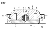
- a cross-section I-I of the machinery brake 20 of an elevator hoisting machine is presented in FIG 1 .
- the frame part 1 of the machinery brake 20 of an elevator hoisting machine is fixed to the stationary machine frame of the hoisting machine with fixing lugs 14.
- an electromagnet which comprises a magnetizing coil 5 and also a coil core 6, which is preferably made of iron.
- the armature part 2 of the machinery brake 20 is movably supported on the frame part 1 with a bolt 15 and a bushing 12 on the bolt 15 in such a way that the armature part 2 is able to move along its determined trajectory in relation to the frame part 1.
- the length of the movement of the armature part 2 can be adjusted by moving the bushing 12 along the bolt 15 and in this way the magnitude of the air gap 10 that is between the armature part 2 and the frame part 1 can also be adjusted.
- the work spring 4 exerts a thrusting force between the frame part 1 and the armature part 2 in such a way that the machinery brake 20 is activated to brake the movement of a rotating part of the hoisting machine when the springs 4 press the armature part 2 against the brake drum 13 of the rotating part of the hoisting machine.
- the operating range of the work spring 4 is dimensioned in such a way that the thrusting force produced by the work spring 4, or by all the work springs 4 together, is constant in relation to the path of movement of the armature part 2 or the thrusting force changes only a little when the location of the armature part 2 changes.
- the machinery brake 20 is opened by supplying current to the magnetizing coil 5 of the electromagnet; the current traveling in the magnetizing coil 5 brings about a force of attraction between the coil core 6 and the magnetic core 3 of the armature part 2 made from magnetizable material, pulling the armature part 2 off the brake drum 13 by resisting the thrusting force of the work spring 4 or work springs 4.
- a damping element which, as in the case presented in FIG 1 and in international patent application publication WO 2012/152998 A2 , can be implemented as a damping plate 7, or as in the case presented in FIG 3 , by means of a damping spring 4 arranged below the armature part 2.
- FIG 4 presents a first embodiment of the damping arrangement 40, according to the invention, of a machinery brake 20 of an elevator.
- the damping arrangement 40 according to the invention can have a damping plate 7 (compare FIG 1 ), but instead it can be omitted.
- the damping arrangement 40 is implemented by machining a number of channels 45 around a magnetizing coil 5 in the frame part 1 of the machinery brake 20 of the elevator hoisting machine.
- the coil core 6, bushing 12 and bolt 15 are, as before, inside the magnetizing coil 5.
- a work spring 4 and one or more damping elements e.g. a damping spring 47, additional damper 50 an additional damper and/or a cup spring 51, are disposed in each channel 45.
- a channel 42 which continues as a narrower channel 49 to below the armature part 2, corresponding to each channel 45 can be machined also in the armature part 2.
- at least one damping element (see above) is fixed into the channels 45 by means of fixings 43, which damping element is situated in the frame part 1 in such a way that the damping spring does not extend into the armature part 2.
- FIG 4 comprises the implementation options A, B, C and D that can be used in connection with both embodiments of our invention.
- a hard elastomer-based or polyurethane-based additional damper 50 At the end of a work spring 4 fixed into a channel 45, preferably at the bottom, is a hard elastomer-based or polyurethane-based additional damper 50.
- a cup spring 51 At the end of a work spring 4 fixed into a channel 45, preferably at the bottom, is a cup spring 51.
- implementation options A and B are implemented most preferably without a guide. Implementation options A and B would not necessarily work. We have also invented what we consider to be the better implementation options C and D:
- a guide pin 49 is arranged inside a work spring 4 fixed into a channel 45.
- the guide pin 49 is supported by, surrounded by, or fixed by means of, a fixing 43 into a channel 42 made in the armature part 2.
- the fixing 43 can comprise an additional damper 51 or can be an additional damper 51.
- damping spring 47 e.g. bundle of cup springs.
- a guide pin 49 is arranged inside a work spring 4 fixed into a channel 45.
- the guide pin 49 travels along a channel made in the armature part 2.
- the tightening bolt 48 of the guide pin 49 most preferably comes through the armature part 2.
- the guide pin 49 is supported by, surrounded by, or fixed by means of, a fixing 43 into a channel 42 made in the armature part 2.
- the fixing 43 can comprise an additional damper or can be an additional damper.
- a damping spring 47 is fixed in a channel 45, 42 by means of the respective fixings 43 in both the frame part 1 and the armature part 2.
- the pretensioning of the damping springs 47 can be adjusted by tightening or loosening the tightening bolt 48.
- a damping arrangement 40 can be implemented by using any whatsoever of the implementation options A - D according to the first or second embodiment, or a combination of any of these.
- the number of channel 45-damping spring combinations comprised in a damping arrangement 40 can be selected to be that needed.
- the number needed can be viably selected to be any whatsoever between two and approx. ten.
- Damping springs 47, additional dampers 50 or cup springs 51 can be used as damping elements in all the different implementations, more particularly therefore also in implementation option D.
Landscapes
- Engineering & Computer Science (AREA)
- General Engineering & Computer Science (AREA)
- Mechanical Engineering (AREA)
- Automation & Control Theory (AREA)
- Computer Networks & Wireless Communication (AREA)
- Physics & Mathematics (AREA)
- Acoustics & Sound (AREA)
- Aviation & Aerospace Engineering (AREA)
- Cage And Drive Apparatuses For Elevators (AREA)
- Braking Arrangements (AREA)
Abstract
Description
- The invention relates particularly to machinery brakes to be used in elevators and to the implementation of said brakes.
- In elevator hoisting machines a machinery brake that mechanically connects with a rotating part of the hoisting machine is normally used as a brake device.
- Structurally, a machinery brake can be e.g. a drum brake or a disc brake. The machinery brake is activated by disconnecting the current supply of the electromagnet of the brake. The machinery brake usually comprises springs which, when the brake is activated, press an armature part provided with a brake pad against the braking surface of a rotating part to brake the movement of the rotating part of the hoisting machine.
- The brake is opened by supplying current to the electromagnet of the brake. The brake opens when the electromagnet pulls the brake pad off the braking surface of the rotating part of the hoisting machine by resisting the thrusting force produced by the springs. During a run, current is connected to the electromagnet, in which case the brake is open and the elevator car can move up or down in the elevator hoistway. The brake implementation of an elevator can be e.g. such that the same hoisting machine comprises two or more machinery brakes.
- As the current of the electromagnet decreases, the force exerted by the spring finally exceeds the force of attraction of the electromagnet, and the brake activates. Owing to the imbalance of forces the brake pad strikes against the braking surface of the rotating part of the machine. When the brake opens, the electromagnet again exerts on the armature part a force that is in the opposite direction to the spring force. When the force exerted on the armature part by the electromagnet grows to be greater than the spring force, the air gap between the frame part and the armature part closes, and the armature part strikes against the frame part.
- Collision of the metallic parts of a brake against each other when the brake is activated or opened may cause a disturbing noise. The noise problem is eliminated whenever possible by adding e.g. a separate damper to the air gap between the frame part and the armature part, which damper when the brake is open prevents direct contact between the metal surfaces of the frame part and of the armature part. A damper can be made of an elastic material, such as rubber or polyurethane; a damper can also be implemented with a separate spring dimensioned for this purpose, such as with a helical spring or cup spring.
- The air gap between the frame part and the armature part can vary e.g. owing to manufacturing tolerances of the damper. The force of attraction of the electromagnet decreases as the air gap increases, in which case opening/keeping open the brake requires more current than before. Generally speaking, power losses in the coil of an electromagnet of a brake increase when the air gap increases. When the power losses increase, the operating temperature of the brake rises.
- The damping force achieved by the damper can also decline over the service life of the brake; for example, the damping force of a damper made from polyurethane might gradually decrease owing to the high temperature of the brake. The damping force of a spring, on the other hand, can decrease owing to, inter alia, fatigue. When the damping force decreases, the operating capability, i.e. the ability to dampen the noise of the brake, declines.
- This type of brake is known e.g. from the preamble of the applicant's international patent application publication
WO 2012/152998 A2 . - The first purpose of the invention is to offer an alternative damping arrangement to the arrangement described in patent application
WO 2012/152998 A2 for damping the opening noise of an operational brake of an elevator hoisting machine, which alternative damping arrangement can be used instead of, or in addition to, the damping arrangement in question. The second purpose of the invention is to lengthen the service life of an arrangement for damping the opening noise of an operational brake of an elevator hoisting machine. - The first purpose can be resolved by means of an arrangement for damping the opening noise of an operational brake of an elevator hoisting machine, said arrangement being according to independent claim 1 or parallel
independent claim 2, by means of an operational brake of an elevator hoisting machine according to parallel independent claim 7, and by means of an elevator according to the second parallelindependent claim 8. - The second purpose can be resolved by means of an arrangement for damping the opening noise of an operational brake of an elevator hoisting machine, said arrangement being according to
dependent claim claim - The dependent claims describe preferred embodiments of the arrangement for damping the opening noise of an operational brake of an elevator hoisting machine and preferred embodiments of an elevator.
- The damping arrangement according to the first aspect of the invention for damping the opening noise between the frame part and the armature part of a machinery brake of an elevator hoisting machine, said machinery brake being opened with an electromagnet, comprises a number of channels machined around a magnetizing coil in the frame part of the machinery brake and channels corresponding to them machined in the armature part, into which channels at least one damping element, more particularly a) a damping spring and/or b) a cup spring, is fixed by means of fixings. According to this embodiment the force adjustment of the damping arrangement can be implemented more easily compared to the alternative damping arrangement presented in the following paragraph. The spatial orientation of the armature part can be better controlled by means of the channels and the damping elements fixed into them. Particularly when using a plate-type armature part (see the
reference number 2 used in the drawings), with a damping arrangement implemented according to prior art, the armature part often tries to move one edge first (i.e. unevenly) towards the electromagnet. As a result of the damping arrangement now invented, uneven moving of, in particular, a plate-type armature part towards the electromagnet can be better avoided. - Alternatively, the damping arrangement for damping the opening noise between the frame part and the armature part of a machinery brake of an elevator hoisting machine, said machinery brake being opened with an electromagnet, comprises a number of channels machined around a magnetizing coil in the frame part of the machinery brake, into which channels at least one damping element is fixed by means of fixings, which damping element is situated in the frame part in such a way that the damping element does not extend into the armature part. The implementation costs of this embodiment are smaller than those of the alternative damping arrangement described in the preceding paragraph.
- By means of both damping arrangements, damping can be implemented by means of damping elements. This is an advantage when compared to the state of the art because the spring constant of the damping elements remains constant at typical operating temperatures in a typical machinery brake.
- Generally elastomer-based materials are used as a damping element for damping brake noise, if the solution described in international patent application publication
WO 2012/152998 A2 is not used. When using polyurethane, the hardness of the polyurethane affects the damping force. The inventors know that the hardness obtained from the same material can differ by 5 units on the Shore A hardness scale. In this case the spring properties of a damper element change significantly. - In tests, the materials in current use have proven to be sensitive to temperature. The materials used age quickly at temperatures exceeding 70 C. Other properties known to be dependent on temperature are hardness at a low temperature (hardness causes disturbing brake noise) and thermal expansion (thermal expansion causes brake sagging).
- The size of an elastomer-based or polyurethane-based machinery brake must therefore be made rather large so that the expected service life of the machinery brake can be made to be sufficiently long.
- When using a damping arrangement according to the first aspect of the invention, the properties of the damping springs are better known. The machinery brake can be used when hotter, in which case its size can be reduced. In addition, the brake noise can be brought to remain constant for the whole service life of the machinery brake.
- By using a damping element installed in a channel, tighter temperature-independent magnetic dimensioning of the machinery brake is achieved. At the same time sagging of the machinery brake when hot and disturbing brake noise when cold can be better avoided.
- When the damping arrangement additionally comprises at least one work spring of the machinery brake, which spring is configured to keep the damping elements pretensioned, the service life of the damping springs, and simultaneously the service life of the whole damping arrangement, can be increased. With the connection in series according to
claim 4 of a damping element and a work spring, the damping can be dimensioned in relation to the differences in spring constant of each work spring in such a way that the damping arrangement acts within the limits of the desired tolerance range sufficiently consistently with all the serially-connected damping elements and work springs (or at least with most of them). - In other words, the damping springs are pretensioned by means of the spring force of the work spring, in which case the damping springs are never unloaded. The solution improves the service life of the damping springs: a spring that is not pretensioned might be destroyed after 30, 000 - 40,000 strokes. When using a solution according to the state of the art, a mechanical damping spring would thus be damaged rather quickly in cyclical loading when releasing the load.
- When at least a part of the channels machined into the armature part continue through the armature part as a continuing channel, and wherein a tightening means is installed in the channel continuing in this way for adjusting the pretensioning of the damping springs, the damping force can be adjusted, most preferably for each specific damping element, and in this way the operation of the damping elements can be improved. At the same time it is possible to optimize the operation of the whole damping arrangement. In this way better movement control is achieved for the brake plate or brake drum.
- According to a preferred aspect, the damping arrangement can additionally comprise a brake drum fixed to a rotating part of the hoisting machine.
- The machinery brake of the elevator hoisting machine according to the second aspect of the invention comprises a frame part, an armature part that is movable with respect to the frame part and is installed at the end of the air gap from the frame part, said armature part being moved by means of an electromagnet that is in the frame part towards the frame part for opening the machinery brake and by means of one or more work springs acting between the frame part and the armature part for closing the machinery brake. In addition, the machinery brake of a hoisting machine of an elevator comprises some damping arrangement according to the first aspect of the invention for damping the opening noise between the frame part and the armature part.
- An elevator according to the third aspect of the invention comprises a hoisting machine, comprising at least one rotating part, and also a machinery brake according to the second aspect of the invention, wherein the machinery brake is configured to brake the movement of a rotating part of the hoisting machine.
- The damping arrangement operates effectively if the damping arrangement of a machinery brake in an elevator according to the third aspect of the invention is according to the second aspect of the invention and if at least one work spring of the machinery brake is, when the brake is closed, configured to press the armature part against the braking surface on a rotating part of the hoisting machine.
- The invention is presented in the following in more detail by the aid of an illustrative embodiment presented in the drawing
FIG 4 . The drawings present: - FIG 1
- a cross-section I - I of the machinery brake of the elevator hoisting machine presented in drawing
FIG 2 ; - FIG
- a machinery brake of a hoisting machine of an elevator;
- FIG 3
- an alternative prior-art arrangement for damping the opening noise of a machinery brake; and
- FIG 4
- a damping arrangement according to the invention.
- In all the FIGs the same reference numbers refer to the same technical features.
-
FIG 2 presents amachinery brake 20 of an elevator hoisting machine, said brake being known from the applicant's patent application publicationWO 2012/152998 A2 . A cross-section I-I of themachinery brake 20 of an elevator hoisting machine is presented inFIG 1 . - The frame part 1 of the
machinery brake 20 of an elevator hoisting machine is fixed to the stationary machine frame of the hoisting machine with fixinglugs 14. In the frame part 1 is an electromagnet, which comprises a magnetizingcoil 5 and also acoil core 6, which is preferably made of iron. - The
armature part 2 of themachinery brake 20 is movably supported on the frame part 1 with abolt 15 and abushing 12 on thebolt 15 in such a way that thearmature part 2 is able to move along its determined trajectory in relation to the frame part 1. The length of the movement of thearmature part 2 can be adjusted by moving thebushing 12 along thebolt 15 and in this way the magnitude of theair gap 10 that is between thearmature part 2 and the frame part 1 can also be adjusted. - The
work spring 4, of which there are a number, exerts a thrusting force between the frame part 1 and thearmature part 2 in such a way that themachinery brake 20 is activated to brake the movement of a rotating part of the hoisting machine when thesprings 4 press thearmature part 2 against thebrake drum 13 of the rotating part of the hoisting machine. - The operating range of the
work spring 4 is dimensioned in such a way that the thrusting force produced by thework spring 4, or by all the work springs 4 together, is constant in relation to the path of movement of thearmature part 2 or the thrusting force changes only a little when the location of thearmature part 2 changes. - The
machinery brake 20 is opened by supplying current to the magnetizingcoil 5 of the electromagnet; the current traveling in the magnetizingcoil 5 brings about a force of attraction between thecoil core 6 and themagnetic core 3 of thearmature part 2 made from magnetizable material, pulling thearmature part 2 off thebrake drum 13 by resisting the thrusting force of thework spring 4 or work springs 4. - When the
machinery brake 20 opens and when thearmature part 2 starts to move towards the frame part 1, the force of attraction exerted on thearmature part 2 of the electromagnet starts to increase, because theair gap 10 of the magnetic circuit of themachinery brake 20 between thecoil core 6 and themagnetic core 3 simultaneously starts to decrease. Owing to the increasing force of attraction, the kinetic energy of thearmature part 2 tries to become large, in which case thearmature part 2 would noisily 5 strike against the frame part 1 of themachinery brake 20. - For damping noise in
machinery brakes 20 according to the state of the art, a damping element which, as in the case presented inFIG 1 and in international patent application publicationWO 2012/152998 A2 , can be implemented as a damping plate 7, or as in the case presented inFIG 3 , by means of a dampingspring 4 arranged below thearmature part 2. -
FIG 4 presents a first embodiment of the dampingarrangement 40, according to the invention, of amachinery brake 20 of an elevator. There is not necessarily any need for the dampingarrangement 40 according to the invention to have a damping plate 7 (compareFIG 1 ), but instead it can be omitted. - The damping
arrangement 40 is implemented by machining a number ofchannels 45 around a magnetizingcoil 5 in the frame part 1 of themachinery brake 20 of the elevator hoisting machine. Thecoil core 6,bushing 12 andbolt 15 are, as before, inside the magnetizingcoil 5. - A
work spring 4 and one or more damping elements, e.g. a dampingspring 47,additional damper 50 an additional damper and/or acup spring 51, are disposed in eachchannel 45. - According to a first embodiment a
channel 42, which continues as anarrower channel 49 to below thearmature part 2, corresponding to eachchannel 45 can be machined also in thearmature part 2. According to a second embodiment at least one damping element (see above) is fixed into thechannels 45 by means offixings 43, which damping element is situated in the frame part 1 in such a way that the damping spring does not extend into thearmature part 2. -
FIG 4 comprises the implementation options A, B, C and D that can be used in connection with both embodiments of our invention. - At the end of a
work spring 4 fixed into achannel 45, preferably at the bottom, is a hard elastomer-based or polyurethane-basedadditional damper 50. - At the end of a
work spring 4 fixed into achannel 45, preferably at the bottom, is acup spring 51. - The implementation options A and B are implemented most preferably without a guide. Implementation options A and B would not necessarily work. We have also invented what we consider to be the better implementation options C and D:
- A
guide pin 49 is arranged inside awork spring 4 fixed into achannel 45. Theguide pin 49 is supported by, surrounded by, or fixed by means of, a fixing 43 into achannel 42 made in thearmature part 2. The fixing 43 can comprise anadditional damper 51 or can be anadditional damper 51. - At the end of the
work spring 4 is a damping spring 47 (e.g. bundle of cup springs). - In this way we can better compensate different opening behavior, caused by the tolerance of the work springs 4, at points of the
armature part 2. - A
guide pin 49 is arranged inside awork spring 4 fixed into achannel 45. Theguide pin 49 travels along a channel made in thearmature part 2. The tighteningbolt 48 of theguide pin 49 most preferably comes through thearmature part 2. Theguide pin 49 is supported by, surrounded by, or fixed by means of, a fixing 43 into achannel 42 made in thearmature part 2. The fixing 43 can comprise an additional damper or can be an additional damper. - A damping
spring 47 is fixed in achannel respective fixings 43 in both the frame part 1 and thearmature part 2. By means of thefixings 43, the pretensioning of the dampingsprings 47 can be adjusted by tightening or loosening the tighteningbolt 48. - In summary, for all the implementation options A - D, compared to the solution described by international patent application publication
WO 2012/152998 A2 , the damping elements of themachinery brake 20 are now therefore implemented as integrated work spring packs. - We can implement a damping
arrangement 40 by using any whatsoever of the implementation options A - D according to the first or second embodiment, or a combination of any of these. In this case the number of channel 45-damping spring combinations comprised in a dampingarrangement 40 can be selected to be that needed. The number needed can be viably selected to be any whatsoever between two and approx. ten. - The invention is not limited to the damping elements according to implementation options A D presented above. Damping springs 47,
additional dampers 50 or cup springs 51 can be used as damping elements in all the different implementations, more particularly therefore also in implementation option D. - The invention must not be regarded as being limited only to the claims below but instead should be understood to include all legal equivalents of said claims and combinations of the embodiments presented.
-
- 1
- frame part
- 2
- armature part
- 3
- magnetic core
- 4
- work spring
- 5
- magnetizing coil
- 6
- coil core
- 7
- damping plate
- 8
- countersurface of coil core, on
air gap 10 side - 9
- countersurface of
magnetic core 3 of armature part, onair gap 10 side - 10
- air gap
- 12
- bushing
- 13
- brake drum
- 14
- fixing lug
- 15
- bolt
- 20
- machinery brake
- 39
- damping spring
- 40
- damping arrangement
- 42
- channel
- 43
- fixing
- 45
- channel
- 47
- damping spring (e.g. bundle of cup springs)
- 48
- tightening bolt
- 49
- guide pin
- 50
- additional damper
- 51
- cup spring
Claims (9)
- Damping arrangement (40) for damping the opening noise between the frame part (1) and armature part (2) of a machinery brake (20) of an elevator hoisting machine, said machinery brake being opened with an electromagnet (5, 6, 2), characterized in that the damping arrangement (40) comprises a number of channels (45) machined around a magnetizing coil (5) in the frame part (1) of the machinery brake (20) and channels (42) corresponding to them machined in the armature part (2), into which channels (42, 45) at least one damping element (47, 50, 51), more particularly a) a damping spring and/or b) a cup spring, is fixed by means of fixings (43)
- Damping arrangement (40) for damping the opening noise between the frame part (1) and armature part (2) of a machinery brake (20) of an elevator hoisting machine, said machinery brake being opened with an electromagnet (5, 6, 2), characterized in that the damping arrangement (40) comprises a number of channels (45) machined around a magnetizing coil (5) in the frame part (1) of the machinery brake (20), into which channels (45) at least one damping element (47, 50, 51) is fixed by means of fixings (43), which damping element is situated in the frame part (1) in such a way that the damping element does not extend into the armature part (2).
- Damping arrangement (40) according to claim 1 or 2, which additionally comprises at least one work spring (4) of the machinery brake (20), which spring is configured to keep the damping elements (47, 50, 51) pretensioned.
- Damping arrangement (40) according to claim 3, wherein at least one damping element (47, 50, 51) is fitted into the same channel (45, 52) as the work spring (4), or into a channel consecutive to said channel (45, 52), in such a way that the damping element (47, 50, 51) and the work spring (4) are in series with each other.
- Damping arrangement (40) according to claim 1 or to claims 1 and 3 or to claims 1 and 4, wherein at least a part of the channels (42) machined into the armature part (2) continue through the armature part (2) as a continuing channel (49), and wherein a tightening means (48) is installed in the channel (49) continuing in this way for adjusting the pretensioning of the damping element (47, 50, 51).
- Damping arrangement (40) according to any of claims 1 - 5, which additionally comprises a brake drum (13) fixed to a rotating part of the hoisting machine.
- Machinery brake (20) of an elevator hoisting machine, characterized in that the machinery brake (20) comprises:- a frame part (1);- an armature part (2) that is movable with respect to the frame part (1) and is installed at the end of the air gap (10) from the frame part (1), said armature part being moved by means of an electromagnet (5, 6) that is in the frame part (1) towards the frame part (1) for opening the machinery brake (20) and by means of one or more work springs (4) acting between the frame part (1) and the armature part (2) for closing the machinery brake (20); and- damping arrangement (40) according to any of claims 1 - 6 for damping the opening noise between the frame part (1) and armature part (2).
- Elevator, which comprises a hoisting machine, comprising at least one rotating part, and also a machinery brake (20) according to claim 7, wherein the machinery brake (20) is configured to brake the movement of a rotating part of the hoisting machine.
- Elevator according to claim 8, wherein the damping arrangement (40) of the machinery brake (20) is according to claim 6, and at least one work spring (4) of which arrangement is, when the brake is closed, configured to press the armature part (2) against the braking surface on a rotating part of the hoisting machine.
Applications Claiming Priority (1)
| Application Number | Priority Date | Filing Date | Title |
|---|---|---|---|
| FI20136055A FI124983B (en) | 2013-10-29 | 2013-10-29 | Damping arrangement to attenuate the opening noise of the machine brake on the lifting machinery of a lift, lifting machine for lifts and lift |
Publications (1)
| Publication Number | Publication Date |
|---|---|
| EP2868617A1 true EP2868617A1 (en) | 2015-05-06 |
Family
ID=51903754
Family Applications (1)
| Application Number | Title | Priority Date | Filing Date |
|---|---|---|---|
| EP20140188256 Withdrawn EP2868617A1 (en) | 2013-10-29 | 2014-10-09 | Damping arrangement for damping the opening noise of a machinery brake of an elevator hoisting machine; an elevator hoisting machine, and an elevator |
Country Status (5)
| Country | Link |
|---|---|
| US (1) | US20150114762A1 (en) |
| EP (1) | EP2868617A1 (en) |
| CN (1) | CN104692276A (en) |
| FI (1) | FI124983B (en) |
| HK (1) | HK1211013A1 (en) |
Cited By (1)
| Publication number | Priority date | Publication date | Assignee | Title |
|---|---|---|---|---|
| EP3677539A1 (en) | 2019-01-07 | 2020-07-08 | KONE Corporation | An elevator machinery brake |
Families Citing this family (6)
| Publication number | Priority date | Publication date | Assignee | Title |
|---|---|---|---|---|
| CN107098286B (en) | 2016-02-22 | 2021-05-11 | 奥的斯电梯公司 | Elevator brake and method for replacing shock pad of elevator brake |
| JP6797081B2 (en) * | 2017-06-15 | 2020-12-09 | 株式会社日立製作所 | Electromagnetic brake device, hoist and elevator |
| US11203510B2 (en) | 2018-07-31 | 2021-12-21 | Otis Elevator Company | Electrohydraulic damper for elevator system |
| CN112638817B (en) | 2018-08-22 | 2023-04-04 | 通力股份公司 | Elevator brake apparatus |
| US11597633B2 (en) * | 2018-08-22 | 2023-03-07 | Kone Corporation | Elevator safety brake, elevator and method for testing elevator safety brakes |
| EP4239214B1 (en) * | 2021-10-20 | 2025-03-19 | G Clef Acoustic Ltd. | Insulator |
Citations (7)
| Publication number | Priority date | Publication date | Assignee | Title |
|---|---|---|---|---|
| US3613849A (en) * | 1969-04-21 | 1971-10-19 | Lenze Kg Maschf Hans | Automatic adjusting device for clutches and brakes |
| US4285420A (en) * | 1979-07-23 | 1981-08-25 | Facet Enterprises, Inc. | Air gap adjuster for electric clutches |
| US5067593A (en) * | 1988-12-07 | 1991-11-26 | Hitachi, Ltd. | Braking device for elevator winding machine and elevator using the braking device |
| EP0509784A2 (en) * | 1991-04-15 | 1992-10-21 | Otis Elevator Company | Elevator disc brake |
| EP1431232A1 (en) * | 2001-06-29 | 2004-06-23 | Mitsubishi Denki Kabushiki Kaisha | Elevator hoist and elevator device |
| JP2009046235A (en) * | 2007-08-17 | 2009-03-05 | Mitsubishi Electric Corp | Brake device |
| WO2012152998A2 (en) | 2011-05-12 | 2012-11-15 | Kone Corporation | A brake and a method for making a brake |
Family Cites Families (7)
| Publication number | Priority date | Publication date | Assignee | Title |
|---|---|---|---|---|
| US4982825A (en) * | 1989-05-11 | 1991-01-08 | Sepal | Torque and air gap adjustment mechanism for spring engaged brake or clutch |
| US5739610A (en) * | 1995-04-11 | 1998-04-14 | Otis Elevator Company | Electro-magnetic device |
| JP2000220666A (en) * | 1999-02-01 | 2000-08-08 | Tsubakimoto Chain Co | Muffler for deenergization operating type electromagnetic brake |
| JP3947497B2 (en) * | 2003-06-27 | 2007-07-18 | 三菱電機株式会社 | Brake structure of hoisting machine |
| WO2006049612A1 (en) * | 2004-11-01 | 2006-05-11 | Otis Elevator Company | Elevator disk brake with damping |
| FI20115547A0 (en) * | 2011-06-07 | 2011-06-07 | Kone Corp | Method and arrangement for adjusting the brake |
| DE112013006987T5 (en) * | 2013-04-24 | 2015-12-31 | Mitsubishi Electric Corp. | Braking device and Aufzugshubmaschine which uses these |
-
2013
- 2013-10-29 FI FI20136055A patent/FI124983B/en not_active IP Right Cessation
-
2014
- 2014-10-09 EP EP20140188256 patent/EP2868617A1/en not_active Withdrawn
- 2014-10-28 US US14/525,330 patent/US20150114762A1/en not_active Abandoned
- 2014-10-29 CN CN201410858426.0A patent/CN104692276A/en active Pending
-
2015
- 2015-12-01 HK HK15111790.2A patent/HK1211013A1/en unknown
Patent Citations (7)
| Publication number | Priority date | Publication date | Assignee | Title |
|---|---|---|---|---|
| US3613849A (en) * | 1969-04-21 | 1971-10-19 | Lenze Kg Maschf Hans | Automatic adjusting device for clutches and brakes |
| US4285420A (en) * | 1979-07-23 | 1981-08-25 | Facet Enterprises, Inc. | Air gap adjuster for electric clutches |
| US5067593A (en) * | 1988-12-07 | 1991-11-26 | Hitachi, Ltd. | Braking device for elevator winding machine and elevator using the braking device |
| EP0509784A2 (en) * | 1991-04-15 | 1992-10-21 | Otis Elevator Company | Elevator disc brake |
| EP1431232A1 (en) * | 2001-06-29 | 2004-06-23 | Mitsubishi Denki Kabushiki Kaisha | Elevator hoist and elevator device |
| JP2009046235A (en) * | 2007-08-17 | 2009-03-05 | Mitsubishi Electric Corp | Brake device |
| WO2012152998A2 (en) | 2011-05-12 | 2012-11-15 | Kone Corporation | A brake and a method for making a brake |
Cited By (1)
| Publication number | Priority date | Publication date | Assignee | Title |
|---|---|---|---|---|
| EP3677539A1 (en) | 2019-01-07 | 2020-07-08 | KONE Corporation | An elevator machinery brake |
Also Published As
| Publication number | Publication date |
|---|---|
| FI20136055A7 (en) | 2015-04-15 |
| FI124983B (en) | 2015-04-15 |
| HK1211013A1 (en) | 2016-05-13 |
| CN104692276A (en) | 2015-06-10 |
| US20150114762A1 (en) | 2015-04-30 |
Similar Documents
| Publication | Publication Date | Title |
|---|---|---|
| US20150114762A1 (en) | Damping arrangement for damping the opening noise of a machinery brake of an elevator hoisting machine; an elevator hoisting machine, and an elevator | |
| US9376295B2 (en) | Elevator brake device including permanent magnet bias to apply a braking force | |
| JP5070280B2 (en) | Permanent magnet type elevator disc brake | |
| US7699145B2 (en) | Elevator disk brake with damping | |
| EP2707618B1 (en) | A brake | |
| EP1973829B1 (en) | Guide-rail brake with electro-magnetic activation | |
| US8915482B2 (en) | Solenoid with an armature | |
| US20150108381A1 (en) | Electromagnetic valve apparatus with nonlinear spring | |
| CN106369205B (en) | De-energized closed solenoid valve | |
| US11940024B2 (en) | Electromechanically switchable brake having integral damper structure | |
| EP3089188A1 (en) | Opening and closing device | |
| EP1403203A1 (en) | Elevator hoist and brake device of the elevator hoist | |
| EP2607291B1 (en) | Electromagnetic actuator, brake arrangement comprising the electromagnetic actuator, and a method for reducing the energy consumption of the electromagnetic actuator | |
| EP1687548B1 (en) | Brake and method for adjusting a brake | |
| CN111237363A (en) | Braking device, braking system for elevator and elevator system | |
| EP1687232B1 (en) | Elevator brake and hoisting machine | |
| EP4411780B1 (en) | Device for limiting movement of movable part in electrical equipment | |
| EP1897835A1 (en) | Brake device for elevator | |
| US20250251024A1 (en) | Electromagnetic actuation device and braking or clamping device using the same | |
| KR100847175B1 (en) | Hoist of elevator | |
| EP3677539A1 (en) | An elevator machinery brake | |
| HK1151269B (en) | Elevator brake device including permanent magnet bias to apply a braking force |
Legal Events
| Date | Code | Title | Description |
|---|---|---|---|
| PUAI | Public reference made under article 153(3) epc to a published international application that has entered the european phase |
Free format text: ORIGINAL CODE: 0009012 |
|
| 17P | Request for examination filed |
Effective date: 20141009 |
|
| AK | Designated contracting states |
Kind code of ref document: A1 Designated state(s): AL AT BE BG CH CY CZ DE DK EE ES FI FR GB GR HR HU IE IS IT LI LT LU LV MC MK MT NL NO PL PT RO RS SE SI SK SM TR |
|
| AX | Request for extension of the european patent |
Extension state: BA ME |
|
| R17P | Request for examination filed (corrected) |
Effective date: 20151106 |
|
| RBV | Designated contracting states (corrected) |
Designated state(s): AL AT BE BG CH CY CZ DE DK EE ES FI FR GB GR HR HU IE IS IT LI LT LU LV MC MK MT NL NO PL PT RO RS SE SI SK SM TR |
|
| 17Q | First examination report despatched |
Effective date: 20160229 |
|
| GRAP | Despatch of communication of intention to grant a patent |
Free format text: ORIGINAL CODE: EPIDOSNIGR1 |
|
| INTG | Intention to grant announced |
Effective date: 20200102 |
|
| STAA | Information on the status of an ep patent application or granted ep patent |
Free format text: STATUS: THE APPLICATION IS DEEMED TO BE WITHDRAWN |
|
| 18D | Application deemed to be withdrawn |
Effective date: 20200603 |