EP2868554A1 - Ballast assembly - Google Patents
Ballast assembly Download PDFInfo
- Publication number
- EP2868554A1 EP2868554A1 EP20140190094 EP14190094A EP2868554A1 EP 2868554 A1 EP2868554 A1 EP 2868554A1 EP 20140190094 EP20140190094 EP 20140190094 EP 14190094 A EP14190094 A EP 14190094A EP 2868554 A1 EP2868554 A1 EP 2868554A1
- Authority
- EP
- European Patent Office
- Prior art keywords
- ballast
- assembly according
- bracket
- link
- pair
- Prior art date
- Legal status (The legal status is an assumption and is not a legal conclusion. Google has not performed a legal analysis and makes no representation as to the accuracy of the status listed.)
- Granted
Links
- 230000008878 coupling Effects 0.000 claims abstract description 22
- 238000010168 coupling process Methods 0.000 claims abstract description 22
- 238000005859 coupling reaction Methods 0.000 claims abstract description 22
- 230000005540 biological transmission Effects 0.000 description 3
- 239000000446 fuel Substances 0.000 description 1
Images


Classifications
-
- B—PERFORMING OPERATIONS; TRANSPORTING
- B62—LAND VEHICLES FOR TRAVELLING OTHERWISE THAN ON RAILS
- B62D—MOTOR VEHICLES; TRAILERS
- B62D49/00—Tractors
- B62D49/06—Tractors adapted for multi-purpose use
- B62D49/0621—Tractors adapted for multi-purpose use comprising traction increasing arrangements, e.g. all-wheel traction devices, multiple-axle traction arrangements, auxiliary traction increasing devices
- B62D49/0628—Tractors adapted for multi-purpose use comprising traction increasing arrangements, e.g. all-wheel traction devices, multiple-axle traction arrangements, auxiliary traction increasing devices using detachable weights
-
- B—PERFORMING OPERATIONS; TRANSPORTING
- B62—LAND VEHICLES FOR TRAVELLING OTHERWISE THAN ON RAILS
- B62D—MOTOR VEHICLES; TRAILERS
- B62D49/00—Tractors
- B62D49/08—Tractors having means for preventing overturning or tipping
- B62D49/085—Counterweight
Abstract
Description
- The present disclosure relates to a ballast assembly for a work vehicle.
- It is known to ballast a work vehicle, such as a tractor, to accommodate for various mounted implements. Suitcase weights are mounted to the front of the tractor main frame when forward located ballast is desired, and wheel weights are attached to the rear wheels when rearward located ballast is desired. Typically, the mounting of the suitcase weights to the main frame has required the mounting of a separate U-shaped bracket to the front of the main frame while wheel weights are somewhat specially made and are cumbersome to mount.
- It is often desired to change the ballast of the tractor to fit different implements or tasks. For some tasks, like heavy draft pulling, a large ballast weight is needed to improve traction and pull efficiency of the tractor. For some tasks, like high speed transport, ballast may be removed to improve fuel efficiency and increase payload capability. It is desired to have a ballast assembly with which a ballast weight can be quickly attached and detached from a work vehicle.
- According to an aspect of the present disclosure, a ballast assembly is attached to an underside of a work vehicle. The ballast assembly includes a ballast weight which has a central groove in an upper surface thereof. Two pairs of coupling pins extend across the central groove. Two support rods are attached to an underside of a frame part of the vehicle. A first ballast bracket is releasably coupled to the first pair of coupling pins, and a second ballast bracket is releasably coupled to the second pair of coupling pins. A first link has an end pivotally coupled to the first ballast bracket, and has a body which slidably engages the first support rod. A second link has an end pivotally coupled to the second ballast bracket, and has a body which slidably engages the second support rod. An adjustable length actuator, such as a hydraulic cylinder has a first end pivotally coupled to one of the links and having a second end pivotally fixed to the frame part. Each link has a slot which slidably receives a corresponding one of the support rods.
- Each ballast bracket has a body and a pair of curved arms which form a corresponding pair of forwardly opening recesses. Each pair of recess removably receives a corresponding pair of the coupling pins. Each ballast bracket includes a flange which projects from the body, and each flange is pivotally coupled to an end of one of the links. Each ballast bracket includes a latch member which releasably holds the ballast bracket to the corresponding pair of coupling pins. Each ballast bracket includes a latch slot which extends into the body. The latch member includes a bar which is pivotally supported on the body and a latch tab which projects from the bar through the latch slot towards the coupling pin.
-
Fig. 1 is a side view of a tractor with the a ballast assembly embodying the invention; -
Fig. 2 is a front side perspective view of the ballast assembly ofFig. 1 ; -
Fig. 3 is a sectional view along lines 3-3 ofFig. 2 ; -
Fig. 4 is a bottom side perspective view of the structure offig. 3 ; -
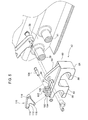
Fig. 5 is an enlarged exploded view of a portion ofFig. 3 ; and -
Fig. 6 is a sectional view of the structure ofFig. 4 . - Referring to
Figs. 1 and2 , awork vehicle 10, such as a tractor, includes a frame part, such as atransmission housing 12 which is positioned between thefront axle 14 and therear axle 16. Aballast weight assembly 15 is attached to an underside of thetransmission housing 12. - As best seen in
Figs. 2 and3 , a pair of front supports 18 and 20 are spaced laterally apart and are attached to the underside of thehousing 12. A pair ofrear supports housing 12. Therear supports front rod 26 is supported by and extends between the front supports 18 and 20. Arear rod 28 is supported by and extends between therear supports - A
ballast weight 30 is coupled to the front and rear supports by alift arm assembly 32. As best seen inFigs. 2 ,3 and4 , theballast weight 30 has an upwardly opening, fore-and-aft extending recess 34 and acentral groove 36 withside walls 38 and 40. Afront ballast bracket 42 is coupled in a forward portion of thegroove 36 topins rear ballast bracket 44 is coupled in a rear portion of thegroove 36 topins Pins grove 36 fromwall 38 to wall 40. Anactuator bracket 46 is also fixed to the underside of thetransmission housing 12. Theballast weight 30 can be any weight. Preferably, theweight 30 would be designed in such a fashion that it maintains a desired weight split between the front and rear axles. - A two-
piece front link 50 includes a rearlower end 52 which is pivotally coupled to thefront ballast bracket 42, aforward front end 54 pivotally coupled to apin 56, and anelongated slot 58 which slidably receives thefront rod 26. A two-piecerear link 60 includes a rearlower end 62 which is pivotally coupled to therear ballast bracket 44, aforward front end 64 pivotally coupled to apin 66, and anelongated slot 68 which slidably receives therear rod 28. An extendable and retractable actuator, 70, such as a hydraulic cylinder, includes aforward end 72 which is pivotally coupled to thebracket 46. Theactuator 70 also includes arear end 74 which is pivotally coupled to thepin 66 between the two pieces of therear link 60. As best seen inFigs. 3 and4 , a pair ofalignment bars pins cylinder 70. - Referring now to
Figs. 4 ,5 and6 , thefront ballast bracket 42 includes abody 80 and a pair ofcurved arms recesses recesses corresponding pins flange 94 projects from the top ofbody 80 and includes abore 96. Bore 96 receives acoupling pin 98 which is pivotally coupled to the lowerrear ends 52 oflink 50. Alatch slot 93 opens at the upper surface ofbody 80 and extends downwardly and forwardly into thebody 80. - A pair of
tabs body 80. Bores 104 and 106 extend thoughtabs latch pin 108. Alatch member 110 includes abar 112 withbores 114 and 116 at opposite ends thereof. Thelatch member 110 also includes alatch tab 118 which extends forwardly and downwardly frombar 112.Latch tab 118 is engagable withpin 39 to releasably holdbracket 42 to thepins Fig. 5 , the lowerrear end 52 of thelink 50 has acoupling bore 120 which receives thecoupling pin 98 and alatch bore 122. Apin 124 is received bybore 122 and bore 116 and pivotally couples thelink 50 to thelatch member 110. thelatch tab 118 is received by thelatch slot 93. Therear ballast bracket 44 has similar structure which releasably holds therear ballast bracket 44 topins - Referring now to
Figs. 3 and5 , thecylinder 70 is extended and theweight 30 is in a fully lowered position. In this lowered position, thelatch tab 118 oflatch member 110 is pulled away from thepin 39 and theweight 30 can be moved to the left relative to thebracket 42 and thepins recesses cylinder 70 is retracted, thelink 50 rotates counterclockwise with respect to thebracket 42. This causeslatch member 110 to rotate clockwise aroundpin 108 until an end oflatch tab 118 engages an upper surface ofpin 39 and thereby prevent removal of theballast weight 30 from thebracket 42. The latch mechanism of therear bracket 44 operates in a similar manner. - The result is an assembly which movably mounts a large weight between the front and rear axles of the tractor below the chassis. The weight can be quickly lowered to the ground by the links that are coupled to the chassis. This allows for rapid change in tractor ballast. The operator would locate the large weight on the ground and line the tractor up to this weight. The tractor is then positioned over the weight and the links are lowered and moved to engage the weight. The links are then raised. The safety latch moves into place at the top of the lift stroke to prevent unwanted lowering of the weight.
Claims (13)
- A ballast assembly for a work vehicle, the ballast assembly comprising:a frame part of the vehicle;a ballast weight;a first support rod attached to an underside of the frame part;a second support rod attached to an underside of the frame part and spaced apart from the first support rod;a first link having an end pivotally coupled to the ballast weight, and having a body which slidably engages the first support rod;a second link having an end pivotally coupled to the ballast weight, and having a body which slidably engages the second support rod; andan adjustable length actuator having a first end pivotally coupled to one of the links and having a second end pivotally coupled to the frame part.
- The ballast assembly according to claim 1, wherein:the ballast weight includes an upwardly opening central groove, and at least two coupling pins extend across the central groove;a first ballast bracket coupled to an end of the first link; anda second ballast bracket coupled to an end of the second link, each ballast bracket releasably receiving at least a corresponding one of the coupling pins.
- The ballast assembly according to claim 2, wherein:each ballast bracket comprises a body and a curved arm which forms a forwardly opening recess, the recess removably receiving a corresponding one of the coupling pins.
- The ballast assembly according to claim 3, wherein:each ballast bracket comprises a flange which projects from the body, the flange being pivotally coupled to an end of one of the links.
- The ballast assembly according to one of the claims 2 to 4, wherein:each ballast bracket comprises a latch member which releasably holds the ballast bracket to the coupling pin.
- The ballast assembly according to claim 5, wherein:each ballast bracket comprises a body and a latch slot which extends into the body;andthe latch member comprises a bar which is pivotally supported on the body and a latch tab which projects from the bar through the latch slot towards the coupling pin.
- The ballast assembly according to one of the claims 1 to 6, wherein:each link has a slot which slidably receives a corresponding one of the support rods.
- The ballast assembly according to one of the claims 1 to 7, wherein:the ballast weight includes a central groove;a first pair of coupling pins extend across the central groove;a second pair of coupling pins extend across the central groove;a first ballast bracket coupled to an end of the first link; anda second ballast bracket coupled to an end of the second link, each ballast bracket releasably receiving a corresponding pair of the coupling pins.
- The ballast assembly according to claim 8, wherein:each ballast bracket comprises a body and a pair of curved arms which form a corresponding pair of recesses, each pair of recess removably receiving a corresponding pair of the coupling pins.
- The ballast assembly according to claim 9, wherein:each ballast bracket comprises a flange which projects from the body, each flange being pivotally coupled to an end of one of the links.
- The ballast assembly according to claim 8 or 9, wherein:each ballast bracket comprises a latch member which releasably holds the ballast bracket to the corresponding pair of coupling pins.
- The ballast assembly according to claim 11, wherein:each ballast bracket comprises a body and a latch slot which extends into the body;andthe latch member comprises a bar which is pivotally supported on the body and a latch tab which projects from the bar through the latch slot towards the coupling pin.
- The ballast assembly according to one of the claims 8 to 12, wherein:each link has a slot which slidably receives a corresponding one of the support rods.
Applications Claiming Priority (1)
| Application Number | Priority Date | Filing Date | Title |
|---|---|---|---|
| US14/068,912 US8925964B1 (en) | 2013-10-31 | 2013-10-31 | Ballast assembly |
Publications (2)
| Publication Number | Publication Date |
|---|---|
| EP2868554A1 true EP2868554A1 (en) | 2015-05-06 |
| EP2868554B1 EP2868554B1 (en) | 2016-10-05 |
Family
ID=51790588
Family Applications (1)
| Application Number | Title | Priority Date | Filing Date |
|---|---|---|---|
| EP14190094.4A Active EP2868554B1 (en) | 2013-10-31 | 2014-10-23 | Ballast assembly |
Country Status (6)
| Country | Link |
|---|---|
| US (1) | US8925964B1 (en) |
| EP (1) | EP2868554B1 (en) |
| JP (1) | JP2015085936A (en) |
| CN (1) | CN104590406B (en) |
| IN (1) | IN2014MU02903A (en) |
| RU (1) | RU2014139285A (en) |
Cited By (3)
| Publication number | Priority date | Publication date | Assignee | Title |
|---|---|---|---|---|
| ITUB20155602A1 (en) * | 2015-11-16 | 2017-05-16 | Sandro Dini | Ballast for operating machine. |
| CN110182125A (en) * | 2019-05-06 | 2019-08-30 | 江苏理工学院 | Tank truck rollover composite protective system and its control method based on hydraulic buffer |
| CN110217155A (en) * | 2019-05-06 | 2019-09-10 | 江苏理工学院 | Tank truck rollover composite protective system and its control process based on air bag |
Families Citing this family (7)
| Publication number | Priority date | Publication date | Assignee | Title |
|---|---|---|---|---|
| GB201317493D0 (en) * | 2013-10-03 | 2013-11-20 | Agco Int Gmbh | Tractor counterweight mounting |
| WO2017062445A1 (en) | 2015-10-05 | 2017-04-13 | 3M Innovative Properties Company | Apparatus and method for automatically applying weight material to a wheel |
| US10293874B2 (en) | 2016-04-26 | 2019-05-21 | Agco Corporation | Self mounting ballast weight system |
| US9957001B1 (en) * | 2016-11-02 | 2018-05-01 | Deere & Company | Ballast assembly for a work vehicle |
| CN106769103B (en) * | 2017-01-24 | 2023-08-04 | 一汽-大众汽车有限公司 | Front counterweight assembly for vehicle collision test |
| US11027787B2 (en) | 2017-10-31 | 2021-06-08 | Deere & Company | Attachment assembly for use with a work machine |
| US11858564B2 (en) | 2021-08-17 | 2024-01-02 | Cnh Industrial America Llc | Vehicle with repositionable ballast |
Citations (5)
| Publication number | Priority date | Publication date | Assignee | Title |
|---|---|---|---|---|
| DE804269C (en) * | 1949-06-01 | 1951-04-19 | Heinrich Lanz Akt Ges | Tractor with removable loading weight |
| FR1285451A (en) * | 1961-01-20 | 1962-02-23 | Improvements to motor vehicles and in particular to agricultural tractors | |
| US3220582A (en) * | 1964-12-10 | 1965-11-30 | John S Pilch | Tractor mounted counterweight |
| JPS59153668A (en) * | 1983-02-22 | 1984-09-01 | Iseki & Co Ltd | Weight for tractor |
| EP0315595A2 (en) * | 1987-11-02 | 1989-05-10 | SAME S.p.A. | A metal-mass ballasting device for tractors |
Family Cites Families (14)
| Publication number | Priority date | Publication date | Assignee | Title |
|---|---|---|---|---|
| US3853231A (en) * | 1972-08-21 | 1974-12-10 | Caterpillar Tractor Co | Vehicle counterweight apparatus |
| US4232883A (en) * | 1979-03-19 | 1980-11-11 | Ford Motor Company | Counterweight assembly for a vehicle |
| DE3223990A1 (en) * | 1982-06-26 | 1983-12-29 | Klöckner-Humboldt-Deutz AG, 5000 Köln | Farming tractor having a removable ballast weight |
| JPH0739676B2 (en) * | 1989-03-15 | 1995-05-01 | 東洋運搬機株式会社 | Vehicle with balance device |
| US6328121B1 (en) * | 1999-03-31 | 2001-12-11 | Richard W. Woodbury | Ultra-narrow automobile stabilized with ballast |
| JP4196375B2 (en) * | 2003-02-04 | 2008-12-17 | 株式会社小松製作所 | Counterweight |
| JP2004360232A (en) * | 2003-06-02 | 2004-12-24 | Komatsu Ltd | Working vehicle |
| US6988560B2 (en) * | 2003-10-29 | 2006-01-24 | Cnh America Llc | Quick attachment system |
| CN100567133C (en) * | 2004-07-07 | 2009-12-09 | 日立住友重机械建机起重机株式会社 | The counter weight device that is used for vehicle for construction |
| CN2765452Y (en) * | 2004-11-30 | 2006-03-22 | 杨文伟 | Anti-corrosion intensified combined counter weight for roller tractor |
| JP5122786B2 (en) * | 2005-11-18 | 2013-01-16 | 株式会社小松製作所 | Counterweight attachment / detachment device |
| US8118326B2 (en) * | 2010-07-12 | 2012-02-21 | Husqvarna Professional Products, Inc. | Toolless quick detach weight system |
| GB201017368D0 (en) | 2010-10-14 | 2010-11-24 | Agco Int Gmbh | Tractor weight arrangement |
| US8434787B2 (en) * | 2011-06-10 | 2013-05-07 | Caterpillar Inc. | Counterweight attachment and removal system and machine using same |
-
2013
- 2013-10-31 US US14/068,912 patent/US8925964B1/en active Active
-
2014
- 2014-09-11 IN IN2903MU2014 patent/IN2014MU02903A/en unknown
- 2014-09-29 RU RU2014139285A patent/RU2014139285A/en not_active Application Discontinuation
- 2014-10-23 EP EP14190094.4A patent/EP2868554B1/en active Active
- 2014-10-28 CN CN201410589975.2A patent/CN104590406B/en active Active
- 2014-10-28 JP JP2014219322A patent/JP2015085936A/en active Pending
Patent Citations (5)
| Publication number | Priority date | Publication date | Assignee | Title |
|---|---|---|---|---|
| DE804269C (en) * | 1949-06-01 | 1951-04-19 | Heinrich Lanz Akt Ges | Tractor with removable loading weight |
| FR1285451A (en) * | 1961-01-20 | 1962-02-23 | Improvements to motor vehicles and in particular to agricultural tractors | |
| US3220582A (en) * | 1964-12-10 | 1965-11-30 | John S Pilch | Tractor mounted counterweight |
| JPS59153668A (en) * | 1983-02-22 | 1984-09-01 | Iseki & Co Ltd | Weight for tractor |
| EP0315595A2 (en) * | 1987-11-02 | 1989-05-10 | SAME S.p.A. | A metal-mass ballasting device for tractors |
Cited By (7)
| Publication number | Priority date | Publication date | Assignee | Title |
|---|---|---|---|---|
| ITUB20155602A1 (en) * | 2015-11-16 | 2017-05-16 | Sandro Dini | Ballast for operating machine. |
| WO2017085620A1 (en) * | 2015-11-16 | 2017-05-26 | Dini Sandro | Ballast for operating machine |
| US11014620B2 (en) | 2015-11-16 | 2021-05-25 | Sandro DINI | Ballast for operating machine |
| CN110182125A (en) * | 2019-05-06 | 2019-08-30 | 江苏理工学院 | Tank truck rollover composite protective system and its control method based on hydraulic buffer |
| CN110217155A (en) * | 2019-05-06 | 2019-09-10 | 江苏理工学院 | Tank truck rollover composite protective system and its control process based on air bag |
| CN110182125B (en) * | 2019-05-06 | 2021-06-15 | 江苏理工学院 | Hydraulic shock absorber-based tank truck rollover composite protection system and control method thereof |
| CN110217155B (en) * | 2019-05-06 | 2021-08-24 | 江苏理工学院 | Side-turning composite protection system of tank truck based on safety air bag and control process of side-turning composite protection system |
Also Published As
| Publication number | Publication date |
|---|---|
| CN104590406B (en) | 2018-05-25 |
| US8925964B1 (en) | 2015-01-06 |
| EP2868554B1 (en) | 2016-10-05 |
| RU2014139285A (en) | 2016-04-20 |
| IN2014MU02903A (en) | 2015-10-09 |
| JP2015085936A (en) | 2015-05-07 |
| CN104590406A (en) | 2015-05-06 |
Similar Documents
| Publication | Publication Date | Title |
|---|---|---|
| EP2868554B1 (en) | Ballast assembly | |
| US5113956A (en) | Forwardly folding tool bar | |
| CA2534702C (en) | Tongue swing cylinder arrangement for rotary side-pull mower-conditioner | |
| US4181181A (en) | Tractor implement hitch with rubbing surfaces to limit sway | |
| CA2789618C (en) | Rear folding tool bar implement | |
| US8381422B2 (en) | Method and means for converting a blade attachment of an off-road vehicle to a quick-attach blade | |
| US20200346505A1 (en) | Height Adjustable Implement Mount for Single-Point Hitch Equipped Vehicles | |
| US8740249B1 (en) | Combine header transport trailer | |
| US10293874B2 (en) | Self mounting ballast weight system | |
| US4106788A (en) | Hoe drill carrier | |
| NL1029929C2 (en) | Front trailed linkage for hitching mower to tractor, has machine and support frames connected by pivoting support arms which allow side shift of mower around obstacles | |
| FI65527C (en) | FORDONSBUREN BAERARE FOER SKOGSBRUKSREDSKAP | |
| EP3272196B1 (en) | An agricultural implement | |
| US3974880A (en) | Drawbar assembly | |
| US10801172B2 (en) | Snow plow assembly with floating a-frame | |
| CN102359137A (en) | Land scraper and loosening device thereof | |
| KR102040980B1 (en) | Tractor attachment detachable device | |
| EP2140748A1 (en) | Tractor hitches | |
| KR20130108216A (en) | A harrow for tractor | |
| US4032169A (en) | Drawbar assembly | |
| US2788728A (en) | Cultivating attachment for tractors | |
| US4220210A (en) | Tractor front supported implement attachment frame | |
| JP2012091901A (en) | Attachment type forklift in tractor | |
| RU2634950C1 (en) | Rear hinged device of agricultural tractor | |
| USRE23726E (en) | Hydraulic tool supporting |
Legal Events
| Date | Code | Title | Description |
|---|---|---|---|
| PUAI | Public reference made under article 153(3) epc to a published international application that has entered the european phase |
Free format text: ORIGINAL CODE: 0009012 |
|
| 17P | Request for examination filed |
Effective date: 20141023 |
|
| AK | Designated contracting states |
Kind code of ref document: A1 Designated state(s): AL AT BE BG CH CY CZ DE DK EE ES FI FR GB GR HR HU IE IS IT LI LT LU LV MC MK MT NL NO PL PT RO RS SE SI SK SM TR |
|
| AX | Request for extension of the european patent |
Extension state: BA ME |
|
| R17P | Request for examination filed (corrected) |
Effective date: 20151106 |
|
| RBV | Designated contracting states (corrected) |
Designated state(s): AL AT BE BG CH CY CZ DE DK EE ES FI FR GB GR HR HU IE IS IT LI LT LU LV MC MK MT NL NO PL PT RO RS SE SI SK SM TR |
|
| RIC1 | Information provided on ipc code assigned before grant |
Ipc: B62D 37/04 20060101AFI20160317BHEP Ipc: B62D 49/08 20060101ALI20160317BHEP Ipc: B62D 49/06 20060101ALI20160317BHEP |
|
| GRAP | Despatch of communication of intention to grant a patent |
Free format text: ORIGINAL CODE: EPIDOSNIGR1 |
|
| INTG | Intention to grant announced |
Effective date: 20160425 |
|
| GRAS | Grant fee paid |
Free format text: ORIGINAL CODE: EPIDOSNIGR3 |
|
| GRAA | (expected) grant |
Free format text: ORIGINAL CODE: 0009210 |
|
| AK | Designated contracting states |
Kind code of ref document: B1 Designated state(s): AL AT BE BG CH CY CZ DE DK EE ES FI FR GB GR HR HU IE IS IT LI LT LU LV MC MK MT NL NO PL PT RO RS SE SI SK SM TR |
|
| REG | Reference to a national code |
Ref country code: GB Ref legal event code: FG4D |
|
| REG | Reference to a national code |
Ref country code: CH Ref legal event code: EP |
|
| REG | Reference to a national code |
Ref country code: AT Ref legal event code: REF Ref document number: 834354 Country of ref document: AT Kind code of ref document: T Effective date: 20161015 |
|
| REG | Reference to a national code |
Ref country code: IE Ref legal event code: FG4D |
|
| REG | Reference to a national code |
Ref country code: DE Ref legal event code: R096 Ref document number: 602014004079 Country of ref document: DE |
|
| REG | Reference to a national code |
Ref country code: NL Ref legal event code: MP Effective date: 20161005 |
|
| REG | Reference to a national code |
Ref country code: LT Ref legal event code: MG4D |
|
| PG25 | Lapsed in a contracting state [announced via postgrant information from national office to epo] |
Ref country code: LV Free format text: LAPSE BECAUSE OF FAILURE TO SUBMIT A TRANSLATION OF THE DESCRIPTION OR TO PAY THE FEE WITHIN THE PRESCRIBED TIME-LIMIT Effective date: 20161005 Ref country code: BE Free format text: LAPSE BECAUSE OF NON-PAYMENT OF DUE FEES Effective date: 20161031 |
|
| REG | Reference to a national code |
Ref country code: AT Ref legal event code: MK05 Ref document number: 834354 Country of ref document: AT Kind code of ref document: T Effective date: 20161005 |
|
| PG25 | Lapsed in a contracting state [announced via postgrant information from national office to epo] |
Ref country code: NO Free format text: LAPSE BECAUSE OF FAILURE TO SUBMIT A TRANSLATION OF THE DESCRIPTION OR TO PAY THE FEE WITHIN THE PRESCRIBED TIME-LIMIT Effective date: 20170105 Ref country code: LT Free format text: LAPSE BECAUSE OF FAILURE TO SUBMIT A TRANSLATION OF THE DESCRIPTION OR TO PAY THE FEE WITHIN THE PRESCRIBED TIME-LIMIT Effective date: 20161005 Ref country code: GR Free format text: LAPSE BECAUSE OF FAILURE TO SUBMIT A TRANSLATION OF THE DESCRIPTION OR TO PAY THE FEE WITHIN THE PRESCRIBED TIME-LIMIT Effective date: 20170106 Ref country code: SE Free format text: LAPSE BECAUSE OF FAILURE TO SUBMIT A TRANSLATION OF THE DESCRIPTION OR TO PAY THE FEE WITHIN THE PRESCRIBED TIME-LIMIT Effective date: 20161005 |
|
| PG25 | Lapsed in a contracting state [announced via postgrant information from national office to epo] |
Ref country code: RS Free format text: LAPSE BECAUSE OF FAILURE TO SUBMIT A TRANSLATION OF THE DESCRIPTION OR TO PAY THE FEE WITHIN THE PRESCRIBED TIME-LIMIT Effective date: 20161005 Ref country code: HR Free format text: LAPSE BECAUSE OF FAILURE TO SUBMIT A TRANSLATION OF THE DESCRIPTION OR TO PAY THE FEE WITHIN THE PRESCRIBED TIME-LIMIT Effective date: 20161005 Ref country code: BE Free format text: LAPSE BECAUSE OF FAILURE TO SUBMIT A TRANSLATION OF THE DESCRIPTION OR TO PAY THE FEE WITHIN THE PRESCRIBED TIME-LIMIT Effective date: 20161005 Ref country code: AT Free format text: LAPSE BECAUSE OF FAILURE TO SUBMIT A TRANSLATION OF THE DESCRIPTION OR TO PAY THE FEE WITHIN THE PRESCRIBED TIME-LIMIT Effective date: 20161005 Ref country code: ES Free format text: LAPSE BECAUSE OF FAILURE TO SUBMIT A TRANSLATION OF THE DESCRIPTION OR TO PAY THE FEE WITHIN THE PRESCRIBED TIME-LIMIT Effective date: 20161005 Ref country code: NL Free format text: LAPSE BECAUSE OF FAILURE TO SUBMIT A TRANSLATION OF THE DESCRIPTION OR TO PAY THE FEE WITHIN THE PRESCRIBED TIME-LIMIT Effective date: 20161005 Ref country code: PL Free format text: LAPSE BECAUSE OF FAILURE TO SUBMIT A TRANSLATION OF THE DESCRIPTION OR TO PAY THE FEE WITHIN THE PRESCRIBED TIME-LIMIT Effective date: 20161005 Ref country code: FI Free format text: LAPSE BECAUSE OF FAILURE TO SUBMIT A TRANSLATION OF THE DESCRIPTION OR TO PAY THE FEE WITHIN THE PRESCRIBED TIME-LIMIT Effective date: 20161005 Ref country code: PT Free format text: LAPSE BECAUSE OF FAILURE TO SUBMIT A TRANSLATION OF THE DESCRIPTION OR TO PAY THE FEE WITHIN THE PRESCRIBED TIME-LIMIT Effective date: 20170206 Ref country code: IS Free format text: LAPSE BECAUSE OF FAILURE TO SUBMIT A TRANSLATION OF THE DESCRIPTION OR TO PAY THE FEE WITHIN THE PRESCRIBED TIME-LIMIT Effective date: 20170205 |
|
| REG | Reference to a national code |
Ref country code: DE Ref legal event code: R097 Ref document number: 602014004079 Country of ref document: DE |
|
| REG | Reference to a national code |
Ref country code: IE Ref legal event code: MM4A |
|
| PG25 | Lapsed in a contracting state [announced via postgrant information from national office to epo] |
Ref country code: RO Free format text: LAPSE BECAUSE OF FAILURE TO SUBMIT A TRANSLATION OF THE DESCRIPTION OR TO PAY THE FEE WITHIN THE PRESCRIBED TIME-LIMIT Effective date: 20161005 Ref country code: CZ Free format text: LAPSE BECAUSE OF FAILURE TO SUBMIT A TRANSLATION OF THE DESCRIPTION OR TO PAY THE FEE WITHIN THE PRESCRIBED TIME-LIMIT Effective date: 20161005 Ref country code: DK Free format text: LAPSE BECAUSE OF FAILURE TO SUBMIT A TRANSLATION OF THE DESCRIPTION OR TO PAY THE FEE WITHIN THE PRESCRIBED TIME-LIMIT Effective date: 20161005 Ref country code: MC Free format text: LAPSE BECAUSE OF FAILURE TO SUBMIT A TRANSLATION OF THE DESCRIPTION OR TO PAY THE FEE WITHIN THE PRESCRIBED TIME-LIMIT Effective date: 20161005 Ref country code: SK Free format text: LAPSE BECAUSE OF FAILURE TO SUBMIT A TRANSLATION OF THE DESCRIPTION OR TO PAY THE FEE WITHIN THE PRESCRIBED TIME-LIMIT Effective date: 20161005 Ref country code: EE Free format text: LAPSE BECAUSE OF FAILURE TO SUBMIT A TRANSLATION OF THE DESCRIPTION OR TO PAY THE FEE WITHIN THE PRESCRIBED TIME-LIMIT Effective date: 20161005 |
|
| PLBE | No opposition filed within time limit |
Free format text: ORIGINAL CODE: 0009261 |
|
| STAA | Information on the status of an ep patent application or granted ep patent |
Free format text: STATUS: NO OPPOSITION FILED WITHIN TIME LIMIT |
|
| PG25 | Lapsed in a contracting state [announced via postgrant information from national office to epo] |
Ref country code: BG Free format text: LAPSE BECAUSE OF FAILURE TO SUBMIT A TRANSLATION OF THE DESCRIPTION OR TO PAY THE FEE WITHIN THE PRESCRIBED TIME-LIMIT Effective date: 20170105 Ref country code: SM Free format text: LAPSE BECAUSE OF FAILURE TO SUBMIT A TRANSLATION OF THE DESCRIPTION OR TO PAY THE FEE WITHIN THE PRESCRIBED TIME-LIMIT Effective date: 20161005 Ref country code: LU Free format text: LAPSE BECAUSE OF NON-PAYMENT OF DUE FEES Effective date: 20161023 Ref country code: IT Free format text: LAPSE BECAUSE OF FAILURE TO SUBMIT A TRANSLATION OF THE DESCRIPTION OR TO PAY THE FEE WITHIN THE PRESCRIBED TIME-LIMIT Effective date: 20161005 |
|
| REG | Reference to a national code |
Ref country code: FR Ref legal event code: ST Effective date: 20170802 |
|
| 26N | No opposition filed |
Effective date: 20170706 |
|
| PG25 | Lapsed in a contracting state [announced via postgrant information from national office to epo] |
Ref country code: FR Free format text: LAPSE BECAUSE OF NON-PAYMENT OF DUE FEES Effective date: 20161205 |
|
| PG25 | Lapsed in a contracting state [announced via postgrant information from national office to epo] |
Ref country code: IE Free format text: LAPSE BECAUSE OF NON-PAYMENT OF DUE FEES Effective date: 20161023 Ref country code: SI Free format text: LAPSE BECAUSE OF FAILURE TO SUBMIT A TRANSLATION OF THE DESCRIPTION OR TO PAY THE FEE WITHIN THE PRESCRIBED TIME-LIMIT Effective date: 20161005 |
|
| PG25 | Lapsed in a contracting state [announced via postgrant information from national office to epo] |
Ref country code: HU Free format text: LAPSE BECAUSE OF FAILURE TO SUBMIT A TRANSLATION OF THE DESCRIPTION OR TO PAY THE FEE WITHIN THE PRESCRIBED TIME-LIMIT; INVALID AB INITIO Effective date: 20141023 |
|
| REG | Reference to a national code |
Ref country code: CH Ref legal event code: PL |
|
| PG25 | Lapsed in a contracting state [announced via postgrant information from national office to epo] |
Ref country code: MK Free format text: LAPSE BECAUSE OF FAILURE TO SUBMIT A TRANSLATION OF THE DESCRIPTION OR TO PAY THE FEE WITHIN THE PRESCRIBED TIME-LIMIT Effective date: 20161005 Ref country code: CY Free format text: LAPSE BECAUSE OF FAILURE TO SUBMIT A TRANSLATION OF THE DESCRIPTION OR TO PAY THE FEE WITHIN THE PRESCRIBED TIME-LIMIT Effective date: 20161005 Ref country code: MT Free format text: LAPSE BECAUSE OF NON-PAYMENT OF DUE FEES Effective date: 20161031 |
|
| PG25 | Lapsed in a contracting state [announced via postgrant information from national office to epo] |
Ref country code: CH Free format text: LAPSE BECAUSE OF NON-PAYMENT OF DUE FEES Effective date: 20171031 Ref country code: LI Free format text: LAPSE BECAUSE OF NON-PAYMENT OF DUE FEES Effective date: 20171031 |
|
| PG25 | Lapsed in a contracting state [announced via postgrant information from national office to epo] |
Ref country code: TR Free format text: LAPSE BECAUSE OF FAILURE TO SUBMIT A TRANSLATION OF THE DESCRIPTION OR TO PAY THE FEE WITHIN THE PRESCRIBED TIME-LIMIT Effective date: 20161005 |
|
| GBPC | Gb: european patent ceased through non-payment of renewal fee |
Effective date: 20181023 |
|
| PG25 | Lapsed in a contracting state [announced via postgrant information from national office to epo] |
Ref country code: GB Free format text: LAPSE BECAUSE OF NON-PAYMENT OF DUE FEES Effective date: 20181023 |
|
| PG25 | Lapsed in a contracting state [announced via postgrant information from national office to epo] |
Ref country code: AL Free format text: LAPSE BECAUSE OF FAILURE TO SUBMIT A TRANSLATION OF THE DESCRIPTION OR TO PAY THE FEE WITHIN THE PRESCRIBED TIME-LIMIT Effective date: 20161005 |
|
| PGFP | Annual fee paid to national office [announced via postgrant information from national office to epo] |
Ref country code: DE Payment date: 20230920 Year of fee payment: 10 |