EP2868530A1 - Housing with self-mounting feature - Google Patents
Housing with self-mounting feature Download PDFInfo
- Publication number
- EP2868530A1 EP2868530A1 EP20140191586 EP14191586A EP2868530A1 EP 2868530 A1 EP2868530 A1 EP 2868530A1 EP 20140191586 EP20140191586 EP 20140191586 EP 14191586 A EP14191586 A EP 14191586A EP 2868530 A1 EP2868530 A1 EP 2868530A1
- Authority
- EP
- European Patent Office
- Prior art keywords
- housing
- retainer
- base
- panel
- edge
- Prior art date
- Legal status (The legal status is an assumption and is not a legal conclusion. Google has not performed a legal analysis and makes no representation as to the accuracy of the status listed.)
- Granted
Links
Images


Classifications
-
- F—MECHANICAL ENGINEERING; LIGHTING; HEATING; WEAPONS; BLASTING
- F16—ENGINEERING ELEMENTS AND UNITS; GENERAL MEASURES FOR PRODUCING AND MAINTAINING EFFECTIVE FUNCTIONING OF MACHINES OR INSTALLATIONS; THERMAL INSULATION IN GENERAL
- F16B—DEVICES FOR FASTENING OR SECURING CONSTRUCTIONAL ELEMENTS OR MACHINE PARTS TOGETHER, e.g. NAILS, BOLTS, CIRCLIPS, CLAMPS, CLIPS OR WEDGES; JOINTS OR JOINTING
- F16B21/00—Means for preventing relative axial movement of a pin, spigot, shaft or the like and a member surrounding it; Stud-and-socket releasable fastenings
- F16B21/06—Releasable fastening devices with snap-action
- F16B21/065—Releasable fastening devices with snap-action with an additional locking element
-
- F—MECHANICAL ENGINEERING; LIGHTING; HEATING; WEAPONS; BLASTING
- F16—ENGINEERING ELEMENTS AND UNITS; GENERAL MEASURES FOR PRODUCING AND MAINTAINING EFFECTIVE FUNCTIONING OF MACHINES OR INSTALLATIONS; THERMAL INSULATION IN GENERAL
- F16B—DEVICES FOR FASTENING OR SECURING CONSTRUCTIONAL ELEMENTS OR MACHINE PARTS TOGETHER, e.g. NAILS, BOLTS, CIRCLIPS, CLAMPS, CLIPS OR WEDGES; JOINTS OR JOINTING
- F16B1/00—Devices for securing together, or preventing relative movement between, constructional elements or machine parts
- F16B1/02—Means for securing elements of mechanisms after operation
-
- B—PERFORMING OPERATIONS; TRANSPORTING
- B60—VEHICLES IN GENERAL
- B60R—VEHICLES, VEHICLE FITTINGS, OR VEHICLE PARTS, NOT OTHERWISE PROVIDED FOR
- B60R16/00—Electric or fluid circuits specially adapted for vehicles and not otherwise provided for; Arrangement of elements of electric or fluid circuits specially adapted for vehicles and not otherwise provided for
- B60R16/02—Electric or fluid circuits specially adapted for vehicles and not otherwise provided for; Arrangement of elements of electric or fluid circuits specially adapted for vehicles and not otherwise provided for electric constitutive elements
- B60R16/023—Electric or fluid circuits specially adapted for vehicles and not otherwise provided for; Arrangement of elements of electric or fluid circuits specially adapted for vehicles and not otherwise provided for electric constitutive elements for transmission of signals between vehicle parts or subsystems
- B60R16/0238—Electrical distribution centers
-
- F—MECHANICAL ENGINEERING; LIGHTING; HEATING; WEAPONS; BLASTING
- F16—ENGINEERING ELEMENTS AND UNITS; GENERAL MEASURES FOR PRODUCING AND MAINTAINING EFFECTIVE FUNCTIONING OF MACHINES OR INSTALLATIONS; THERMAL INSULATION IN GENERAL
- F16B—DEVICES FOR FASTENING OR SECURING CONSTRUCTIONAL ELEMENTS OR MACHINE PARTS TOGETHER, e.g. NAILS, BOLTS, CIRCLIPS, CLAMPS, CLIPS OR WEDGES; JOINTS OR JOINTING
- F16B5/00—Joining sheets or plates, e.g. panels, to one another or to strips or bars parallel to them
- F16B5/06—Joining sheets or plates, e.g. panels, to one another or to strips or bars parallel to them by means of clamps or clips
- F16B5/0607—Joining sheets or plates, e.g. panels, to one another or to strips or bars parallel to them by means of clamps or clips joining sheets or plates to each other
- F16B5/0621—Joining sheets or plates, e.g. panels, to one another or to strips or bars parallel to them by means of clamps or clips joining sheets or plates to each other in parallel relationship
- F16B5/0664—Joining sheets or plates, e.g. panels, to one another or to strips or bars parallel to them by means of clamps or clips joining sheets or plates to each other in parallel relationship at least one of the sheets or plates having integrally formed or integrally connected snap-in-features
-
- B—PERFORMING OPERATIONS; TRANSPORTING
- B60—VEHICLES IN GENERAL
- B60R—VEHICLES, VEHICLE FITTINGS, OR VEHICLE PARTS, NOT OTHERWISE PROVIDED FOR
- B60R11/00—Arrangements for holding or mounting articles, not otherwise provided for
- B60R2011/0001—Arrangements for holding or mounting articles, not otherwise provided for characterised by position
- B60R2011/0003—Arrangements for holding or mounting articles, not otherwise provided for characterised by position inside the vehicle
- B60R2011/0038—Engine compartment
-
- B—PERFORMING OPERATIONS; TRANSPORTING
- B60—VEHICLES IN GENERAL
- B60R—VEHICLES, VEHICLE FITTINGS, OR VEHICLE PARTS, NOT OTHERWISE PROVIDED FOR
- B60R11/00—Arrangements for holding or mounting articles, not otherwise provided for
- B60R2011/0042—Arrangements for holding or mounting articles, not otherwise provided for characterised by mounting means
- B60R2011/0049—Arrangements for holding or mounting articles, not otherwise provided for characterised by mounting means for non integrated articles
- B60R2011/005—Connection with the vehicle part
- B60R2011/0059—Connection with the vehicle part using clips, clamps, straps or the like
-
- F—MECHANICAL ENGINEERING; LIGHTING; HEATING; WEAPONS; BLASTING
- F16—ENGINEERING ELEMENTS AND UNITS; GENERAL MEASURES FOR PRODUCING AND MAINTAINING EFFECTIVE FUNCTIONING OF MACHINES OR INSTALLATIONS; THERMAL INSULATION IN GENERAL
- F16B—DEVICES FOR FASTENING OR SECURING CONSTRUCTIONAL ELEMENTS OR MACHINE PARTS TOGETHER, e.g. NAILS, BOLTS, CIRCLIPS, CLAMPS, CLIPS OR WEDGES; JOINTS OR JOINTING
- F16B2200/00—Constructional details of connections not covered for in other groups of this subclass
- F16B2200/69—Redundant disconnection blocking means
-
- Y—GENERAL TAGGING OF NEW TECHNOLOGICAL DEVELOPMENTS; GENERAL TAGGING OF CROSS-SECTIONAL TECHNOLOGIES SPANNING OVER SEVERAL SECTIONS OF THE IPC; TECHNICAL SUBJECTS COVERED BY FORMER USPC CROSS-REFERENCE ART COLLECTIONS [XRACs] AND DIGESTS
- Y10—TECHNICAL SUBJECTS COVERED BY FORMER USPC
- Y10T—TECHNICAL SUBJECTS COVERED BY FORMER US CLASSIFICATION
- Y10T403/00—Joints and connections
- Y10T403/16—Joints and connections with adjunctive protector, broken parts retainer, repair, assembly or disassembly feature
- Y10T403/1616—Position or guide means
Definitions
- This disclosure generally relates to a housing for holding components or items, and more specifically relates to a housing with a self-mounting feature for securing the housing to a panel.
- the fuses and relays of an electrical system of a vehicle typically are contained within a housing that attaches to the vehicle.
- Known housing designs require the use of metal nuts and studs to secure the housing to the vehicle.
- An assembly tool such as an electric or pneumatic socket driver, is typically used to tighten the nuts to the studs.
- One drawback of these known housing designs is the cost associated with the use of an assembly tool to secure the housing to the vehicle. Additional drawbacks include the weight and piece cost associated with the use of metal nuts and studs.
- a housing configured to be secured to a front side of a panel.
- the panel defines a back side opposite the front side, and an opening through the panel.
- the opening defines a first edge and a second edge opposite the first edge.
- the housing includes a base that is configured to define a hook that cooperates with the back side and the first edge to secure the housing to the front side.
- the housing further includes a retainer that is slideably coupled to the base and is operable to an unengaged position and an engaged position.
- the retainer is configured to define a blocker portion that cooperates with the second edge to keep the hook adjacent to the first edge when the retainer is in the engaged position
- Fig. 1 illustrates a non-limiting example of a housing 10 configured to be secured to a front side 12 of a panel 14.
- the housing 10 includes a base 16 that is configured to hold the contents (not shown) of the housing 10.
- the housing 10 may also include a cover 18 that attaches to the base 16 and protects the contents of the housing 10.
- the contents of the housing 10 may be electrical components such as fuses and relays of an electrical system of a vehicle, and the panel 14 may be a sheet metal panel of the vehicle.
- the base 16 defines a hook 20 ( Fig. 2 ) that cooperates with a back side 22 of the panel 14 and a first edge 24 ( Fig.
- the base 16 also defines a hook 20A that is similar in design and function to the hook 20, and auxiliary features 28A and 28B that also hook to the panel 14.
- the hook 20A and auxiliary features 28A and 28B assist the hook 20 in supporting the weight of the housing 10.
- the base 16 and cover 18 may be made of plastic.
- the housing 10 also includes a retainer 30 ( Fig. 3 ) that is slideably coupled to the base 16.
- the retainer 30 is operable to an un-engaged position 32 ( Fig. 5 ) and an engaged position 34 ( Fig. 6 ) when the cover 18 is not attached to the base 16.
- the base 16 is secured to the panel 14 when the retainer 30 is moved from the un-engaged position 32 to the engaged position 34.
- the retainer 30 defines a blocker portion 36 that cooperates with a second edge 38 of the opening 26 to keep the hook 20 adjacent to the first edge 24 of the opening 26 when the retainer 30 is in the engaged position 34.
- the base 16 is secured to the panel 14 as a result of the hook 20 being held adjacent to the first edge 24 when the retainer 30 is in the engaged position 34.
- the retainer 30 may be made of plastic.
- the base 16 of the housing 10 may also be configured to define a boss 40 ( Fig. 5 ) that contacts the front side 12 of the panel 14 and cooperates with the weight of the base 16 to align a vertical surface 42 of the hook 20 with the back side 22 of the panel 14. This ensures that the vertical surface 42 of the hook 20 is aligned and engaged with the back side 22 of the panel 14 prior to the retainer 30 being moved to the engaged position 34.
- the base 16 of the housing 10 may further be configured to define a clip portion 44 ( Fig. 5 ) that engages a first slot 46 in the retainer 30 to lock the retainer 30 in the un-engaged position 32, and engages a second slot 48 ( Fig. 6 ) in the retainer 30 to lock the retainer 30 in the engaged position 34.
- This locking feature ensures that the retainer 30 stays in the desired position (i.e. un-engaged position 32 or engaged position 34) prior to and after the base 16 is secured to the panel 14.
- the retainer 30, clip portion 44, and opening 26 may be configured such that the retainer 30 can be moved from the un-engaged position 32 to the engaged position 34 by hand (i.e. without an assembly tool).
- the clip portion 44 of the base 16 may define an indentation 50 ( Figs. 6 and 7 ) that is configured to allow for access to disengage the clip portion 44 from the second slot 48.
- the indentation 50 allows for the retainer 30 to be unlocked from the clip portion 44 with a disassembly tool such as a screw driver with a standard head that fits within the indentation 50. With the clip portion 44 disengaged from the second slot 48, the retainer 30 may then be moved to the un-engaged position 32 unlocking the base 16 from the panel 14. This allows for removal of the base 16 from the panel 14 when or if servicing is required.
- the retainer 30 of the housing 10 may be further configured to define a wing 52 ( Fig. 8 ) that cooperates with an exposed surface 54 of the base 16 to keep the retainer 30 from being dislodged from the base 16 during shipping and handling, or after the base 16 has been secured to the panel 14.
- the cover 18 of the housing 10 may be configured to define a stop 56 ( Fig 3 ) that cooperates with the retainer 30 to keep the housing 10 secured to the panel 14 if the retainer 30 unintentionally moves from the engaged position 34.
- the stop 56 cooperates with a back surface 58 of the blocker portion 36 of the retainer 30 to keep an upper surface 60 of the blocker portion 36 engaged with the second edge 38. This keeps the hook 20 adjacent to the first edge 24.
- a housing 10 with a self-mounting feature is provided.
- the housing 10 provides cost and weight savings when compared to known housing designs that require metal nuts and studs along with the use of an assembly tool to secure the housing. Additionally, the housing 10 eliminates the need for access to the back side 22 of the panel 14 in order to secure the housing 10 when compared to housing designs that utilize loose nuts and bolts to secure the housing.
Landscapes
- Engineering & Computer Science (AREA)
- General Engineering & Computer Science (AREA)
- Mechanical Engineering (AREA)
- Casings For Electric Apparatus (AREA)
- Connection Of Plates (AREA)
- Connection Or Junction Boxes (AREA)
- Lock And Its Accessories (AREA)
Abstract
Description
- This disclosure generally relates to a housing for holding components or items, and more specifically relates to a housing with a self-mounting feature for securing the housing to a panel.
- The fuses and relays of an electrical system of a vehicle typically are contained within a housing that attaches to the vehicle. Known housing designs require the use of metal nuts and studs to secure the housing to the vehicle. An assembly tool, such as an electric or pneumatic socket driver, is typically used to tighten the nuts to the studs. One drawback of these known housing designs is the cost associated with the use of an assembly tool to secure the housing to the vehicle. Additional drawbacks include the weight and piece cost associated with the use of metal nuts and studs.
- In accordance with one embodiment a housing configured to be secured to a front side of a panel is provided. The panel defines a back side opposite the front side, and an opening through the panel. The opening defines a first edge and a second edge opposite the first edge. The housing includes a base that is configured to define a hook that cooperates with the back side and the first edge to secure the housing to the front side. The housing further includes a retainer that is slideably coupled to the base and is operable to an unengaged position and an engaged position. The retainer is configured to define a blocker portion that cooperates with the second edge to keep the hook adjacent to the first edge when the retainer is in the engaged position
- Further features and advantages will appear more clearly on a reading of the following detailed description of the preferred embodiment, which is given by way of non-limiting example only and with reference to the accompanying drawings.
- The present invention will now be described, by way of example with reference to the accompanying drawings, in which:
-
Fig. 1 is a front perspective view of a housing that is secured to a panel in accordance with one embodiment; -
Fig. 2 is a back perspective view of the housing and panel in accordance with one embodiment; -
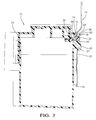
Fig. 3 is a sectional view of the housing and panel in accordance with one embodiment; -
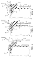
Fig. 4 is a sectional view of the housing with a cover of the housing removed that demonstrates how a hook of a base of the housing is inserted into an opening of the panel; -
Fig. 5 is a sectional view of the housing and panel with a cover of the housing removed and a retainer of the housing in an unengaged position in accordance with one embodiment; -
Fig. 6 is a sectional view similar toFig. 4 with the retainer in an engaged position in accordance with one embodiment; -
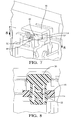
Fig. 7 is a close-up perspective view of the retainer in the engaged position in accordance with one embodiment; and -
Fig. 8 is a close-up sectional view of the retainer and a base of the housing in accordance with one embodiment. -
Fig. 1 illustrates a non-limiting example of ahousing 10 configured to be secured to afront side 12 of apanel 14. Thehousing 10 includes abase 16 that is configured to hold the contents (not shown) of thehousing 10. Thehousing 10 may also include acover 18 that attaches to thebase 16 and protects the contents of thehousing 10. By way of example and not limitation, the contents of thehousing 10 may be electrical components such as fuses and relays of an electrical system of a vehicle, and thepanel 14 may be a sheet metal panel of the vehicle. Thebase 16 defines a hook 20 (Fig. 2 ) that cooperates with aback side 22 of thepanel 14 and a first edge 24 (Fig. 3 ) of anopening 26 of thepanel 14 to secure thehousing 10 to thefront side 12 of thepanel 14. As shown inFig. 4 , thehook 20 is inserted through the opening 26 in thepanel 14 in order to engage thehook 20 with thepanel 14. In the example shown inFig. 2 , thebase 16 also defines ahook 20A that is similar in design and function to thehook 20, andauxiliary features panel 14. Thehook 20A and auxiliary features 28A and 28B assist thehook 20 in supporting the weight of thehousing 10. Thebase 16 andcover 18 may be made of plastic. - The
housing 10 also includes a retainer 30 (Fig. 3 ) that is slideably coupled to thebase 16. In the example shown, theretainer 30 is operable to an un-engaged position 32 (Fig. 5 ) and an engaged position 34 (Fig. 6 ) when thecover 18 is not attached to thebase 16. Thebase 16 is secured to thepanel 14 when theretainer 30 is moved from theun-engaged position 32 to the engagedposition 34. Theretainer 30 defines ablocker portion 36 that cooperates with asecond edge 38 of theopening 26 to keep thehook 20 adjacent to thefirst edge 24 of the opening 26 when theretainer 30 is in the engagedposition 34. Thebase 16 is secured to thepanel 14 as a result of thehook 20 being held adjacent to thefirst edge 24 when theretainer 30 is in the engagedposition 34. Theretainer 30 may be made of plastic. - The
base 16 of thehousing 10 may also be configured to define a boss 40 (Fig. 5 ) that contacts thefront side 12 of thepanel 14 and cooperates with the weight of thebase 16 to align avertical surface 42 of thehook 20 with theback side 22 of thepanel 14. This ensures that thevertical surface 42 of thehook 20 is aligned and engaged with theback side 22 of thepanel 14 prior to theretainer 30 being moved to the engagedposition 34. - The
base 16 of thehousing 10 may further be configured to define a clip portion 44 (Fig. 5 ) that engages afirst slot 46 in theretainer 30 to lock theretainer 30 in theun-engaged position 32, and engages a second slot 48 (Fig. 6 ) in theretainer 30 to lock theretainer 30 in the engagedposition 34. This locking feature ensures that theretainer 30 stays in the desired position (i.e. un-engagedposition 32 or engaged position 34) prior to and after thebase 16 is secured to thepanel 14. Theretainer 30,clip portion 44, and opening 26 may be configured such that theretainer 30 can be moved from theun-engaged position 32 to the engagedposition 34 by hand (i.e. without an assembly tool). - The
clip portion 44 of thebase 16 may define an indentation 50 (Figs. 6 and7 ) that is configured to allow for access to disengage theclip portion 44 from thesecond slot 48. Theindentation 50 allows for theretainer 30 to be unlocked from theclip portion 44 with a disassembly tool such as a screw driver with a standard head that fits within theindentation 50. With theclip portion 44 disengaged from thesecond slot 48, theretainer 30 may then be moved to theun-engaged position 32 unlocking thebase 16 from thepanel 14. This allows for removal of thebase 16 from thepanel 14 when or if servicing is required. - The
retainer 30 of thehousing 10 may be further configured to define a wing 52 (Fig. 8 ) that cooperates with an exposedsurface 54 of thebase 16 to keep theretainer 30 from being dislodged from thebase 16 during shipping and handling, or after thebase 16 has been secured to thepanel 14. - The
cover 18 of thehousing 10 may be configured to define a stop 56 (Fig 3 ) that cooperates with theretainer 30 to keep thehousing 10 secured to thepanel 14 if theretainer 30 unintentionally moves from the engagedposition 34. Thestop 56 cooperates with aback surface 58 of theblocker portion 36 of theretainer 30 to keep anupper surface 60 of theblocker portion 36 engaged with thesecond edge 38. This keeps thehook 20 adjacent to thefirst edge 24. - Accordingly, a
housing 10 with a self-mounting feature is provided. Thehousing 10 provides cost and weight savings when compared to known housing designs that require metal nuts and studs along with the use of an assembly tool to secure the housing. Additionally, thehousing 10 eliminates the need for access to theback side 22 of thepanel 14 in order to secure thehousing 10 when compared to housing designs that utilize loose nuts and bolts to secure the housing. - While this invention has been described in terms of the preferred embodiments thereof, it is not intended to be so limited, but rather only to the extent set forth in the claims that follow.
Claims (6)
- A housing (10) configured to be secured to a front side of a panel (14), wherein the panel (14) defines a back side opposite the front side, and an opening (26) through the panel (14), wherein the opening (26) defines a first edge (24) and a second edge (38) opposite the first edge (24), said housing (10) comprising:a base (16) configured to define a hook (20) that cooperates with the back side and the first edge (24) to secure the housing (10) to the front side; anda retainer (30) slideably coupled to the base (16) and operable to an un-engaged position (32) and an engaged position (34), wherein the retainer (30) is configured to define a blocker portion (36) that cooperates with the second edge (38) to keep the hook (20) adjacent to the first edge (24) when the retainer (30) is in the engaged position (34).
- The housing (10) of claim 1, wherein the base (16) is further configured to define a clip portion (44) that engages a first slot (46) in the retainer (30) to lock the retainer (30) in the un-engaged position (32) and engages a second slot (48) in the retainer (30) to lock the retainer (30) in the engaged position (34).
- The housing (10) of claim 2, wherein the clip portion (44) defines an indentation (50) configured to allow for access to disengage the clip portion (44) from the second slot (48).
- The housing (10) according to one of the claims 1-3, wherein the housing (10) further comprises a cover (18) that attaches to the base (16), wherein the cover (18) is configured to define a stop (56) that cooperates with a back surface (58) of the blocker portion (36) to keep an upper surface (60) of the blocker portion (36) engaged with the second edge (38).
- The housing (10) according to one of the claims 1-4, wherein the retainer (30) is further configured to define a wing (52) that cooperates with an exposed surface (54) of the base (16) to keep the retainer (30) from being dislodged from the base (16).
- The housing (10) according to one of the claims 1-5, wherein the base (16) is further configured to define a boss (40) that contacts the front side and cooperates with the weight of the base (16) to align a vertical surface (42) of the hook (20) with the back side.
Applications Claiming Priority (1)
| Application Number | Priority Date | Filing Date | Title |
|---|---|---|---|
| US14/071,978 US9366281B2 (en) | 2013-11-05 | 2013-11-05 | Housing with self-mounting feature |
Publications (2)
| Publication Number | Publication Date |
|---|---|
| EP2868530A1 true EP2868530A1 (en) | 2015-05-06 |
| EP2868530B1 EP2868530B1 (en) | 2016-06-29 |
Family
ID=51900126
Family Applications (1)
| Application Number | Title | Priority Date | Filing Date |
|---|---|---|---|
| EP14191586.8A Active EP2868530B1 (en) | 2013-11-05 | 2014-11-04 | Housing with self-mounting feature |
Country Status (6)
| Country | Link |
|---|---|
| US (1) | US9366281B2 (en) |
| EP (1) | EP2868530B1 (en) |
| JP (1) | JP6193204B2 (en) |
| KR (1) | KR101676530B1 (en) |
| CN (1) | CN104613059B (en) |
| BR (1) | BR102014018634A2 (en) |
Families Citing this family (6)
| Publication number | Priority date | Publication date | Assignee | Title |
|---|---|---|---|---|
| JP6274852B2 (en) * | 2013-12-17 | 2018-02-07 | カルソニックカンセイ株式会社 | Mounting structure for in-vehicle equipment |
| JP6282625B2 (en) * | 2015-10-22 | 2018-02-21 | 株式会社ミツバ | Control unit for washer device and mounting structure thereof |
| JP6682958B2 (en) * | 2016-03-31 | 2020-04-15 | アイシン精機株式会社 | Vehicle seat slide device |
| US10865819B2 (en) * | 2016-05-20 | 2020-12-15 | Yazaki North America, Inc. | Tuneless cantilever system |
| US10808657B2 (en) * | 2018-02-02 | 2020-10-20 | Ford Global Technologies, Llc | Vehicle component with an accessory mounting feature and a method and tool for forming |
| US11205819B2 (en) * | 2019-04-04 | 2021-12-21 | The Raymond Corporation | Systems and methods for a battery panel assembly on a material handling vehicle |
Citations (4)
| Publication number | Priority date | Publication date | Assignee | Title |
|---|---|---|---|---|
| DE19619164A1 (en) * | 1996-05-11 | 1997-11-20 | Bosch Gmbh Robert | Device for fastening a device |
| EP0795090B1 (en) * | 1994-12-02 | 2001-08-29 | Lear Donnelly Overhead Systems, L.L.C. | Mounting clip |
| EP1323590A2 (en) * | 2001-12-28 | 2003-07-02 | Yazaki Corporation | Structure of installation |
| EP1387091B1 (en) * | 2002-08-02 | 2005-03-30 | Robert Bosch Gmbh | Fastening device |
Family Cites Families (8)
| Publication number | Priority date | Publication date | Assignee | Title |
|---|---|---|---|---|
| US4635809A (en) * | 1985-11-18 | 1987-01-13 | Rca Corporation | Television cabinet having snap-together assembly |
| US4771910A (en) * | 1987-10-13 | 1988-09-20 | United Technologies Automotive, Inc. | Top and housing with peripheral, resilient interface |
| US4836408A (en) * | 1987-10-13 | 1989-06-06 | United Technologies Automotive, Inc. | Integral latching arm |
| DE20308234U1 (en) * | 2003-05-27 | 2003-08-21 | Schwarz Verbindungssysteme GmbH, 75382 Althengstett | Arrangement for receiving a releasably lockable insert element |
| US8045337B2 (en) * | 2008-04-03 | 2011-10-25 | Delphi Technologies, Inc. | Lock for a housing |
| CN102338142A (en) * | 2010-07-16 | 2012-02-01 | 深圳富泰宏精密工业有限公司 | Clamping structure and electronic device employing same |
| DE102010027372A1 (en) * | 2010-07-16 | 2011-03-17 | Daimler Ag | Fastening device for fastening two bodies of motor vehicle, has locking pin retracted in through hole of body on outer circumference, and two notches, which correspond to snap-in pin arranged at inner circumference of through hole of body |
| JP5788268B2 (en) * | 2011-08-31 | 2015-09-30 | 大和化成工業株式会社 | Mounting structure with clips |
-
2013
- 2013-11-05 US US14/071,978 patent/US9366281B2/en active Active
-
2014
- 2014-07-29 BR BR102014018634A patent/BR102014018634A2/en not_active IP Right Cessation
- 2014-07-31 KR KR1020140097936A patent/KR101676530B1/en active Active
- 2014-08-15 CN CN201410403435.0A patent/CN104613059B/en active Active
- 2014-10-29 JP JP2014220230A patent/JP6193204B2/en active Active
- 2014-11-04 EP EP14191586.8A patent/EP2868530B1/en active Active
Patent Citations (4)
| Publication number | Priority date | Publication date | Assignee | Title |
|---|---|---|---|---|
| EP0795090B1 (en) * | 1994-12-02 | 2001-08-29 | Lear Donnelly Overhead Systems, L.L.C. | Mounting clip |
| DE19619164A1 (en) * | 1996-05-11 | 1997-11-20 | Bosch Gmbh Robert | Device for fastening a device |
| EP1323590A2 (en) * | 2001-12-28 | 2003-07-02 | Yazaki Corporation | Structure of installation |
| EP1387091B1 (en) * | 2002-08-02 | 2005-03-30 | Robert Bosch Gmbh | Fastening device |
Also Published As
| Publication number | Publication date |
|---|---|
| KR20150051863A (en) | 2015-05-13 |
| JP6193204B2 (en) | 2017-09-06 |
| US9366281B2 (en) | 2016-06-14 |
| EP2868530B1 (en) | 2016-06-29 |
| CN104613059A (en) | 2015-05-13 |
| KR101676530B1 (en) | 2016-11-15 |
| US20150125200A1 (en) | 2015-05-07 |
| JP2015089811A (en) | 2015-05-11 |
| BR102014018634A2 (en) | 2015-09-29 |
| CN104613059B (en) | 2017-03-15 |
Similar Documents
| Publication | Publication Date | Title |
|---|---|---|
| EP2868530B1 (en) | Housing with self-mounting feature | |
| EP3287712B1 (en) | Attachment structure for water heater | |
| US10220791B2 (en) | Component mounting structure | |
| CN109155379B (en) | Battery fastening system and method | |
| CN105247228A (en) | Clip and pillar garnish mounting structure | |
| CN102574468A (en) | Vehicle instrument panel structure | |
| US9945407B2 (en) | System composed of a sill panel and a fastening clip | |
| JP2011037589A (en) | Elevator car | |
| CN110997412B (en) | Device for receiving objects in a motor vehicle | |
| JP2015020470A (en) | Finisher mounting part structure for vehicle | |
| US10090654B1 (en) | Junction box assembly with eyelet terminal cover retention system and removable eyelet terminal cover | |
| CN106605070A (en) | Retainer | |
| JP2011138984A (en) | Attaching/detaching structure and electronic device using the same | |
| CN107923194B (en) | Lock holders for motor vehicle locking systems | |
| CN103204112B (en) | The installation constitution of inner-decoration component and instrument panel structure | |
| CN104659721B (en) | Electric circuit connection container | |
| JP2010163094A (en) | Installation structure of partition member for cargo room | |
| KR101570086B1 (en) | Door locking device for cabinet | |
| JP2014172457A (en) | Hood fitting structure of display device for vehicle | |
| US20150114060A1 (en) | Clamping device, locking cylinder arrangement and motor vehicle | |
| JP6127474B2 (en) | Instrument panel bottom cover mounting structure | |
| US8061167B2 (en) | Car handler lock | |
| EP2072352A1 (en) | Lock for steering wheel | |
| JP6836919B2 (en) | Fixture | |
| JP5483104B2 (en) | Locking structure for vehicle tonneau cover |
Legal Events
| Date | Code | Title | Description |
|---|---|---|---|
| PUAI | Public reference made under article 153(3) epc to a published international application that has entered the european phase |
Free format text: ORIGINAL CODE: 0009012 |
|
| 17P | Request for examination filed |
Effective date: 20141104 |
|
| AK | Designated contracting states |
Kind code of ref document: A1 Designated state(s): AL AT BE BG CH CY CZ DE DK EE ES FI FR GB GR HR HU IE IS IT LI LT LU LV MC MK MT NL NO PL PT RO RS SE SI SK SM TR |
|
| AX | Request for extension of the european patent |
Extension state: BA ME |
|
| R17P | Request for examination filed (corrected) |
Effective date: 20151106 |
|
| RBV | Designated contracting states (corrected) |
Designated state(s): AL AT BE BG CH CY CZ DE DK EE ES FI FR GB GR HR HU IE IS IT LI LT LU LV MC MK MT NL NO PL PT RO RS SE SI SK SM TR |
|
| GRAP | Despatch of communication of intention to grant a patent |
Free format text: ORIGINAL CODE: EPIDOSNIGR1 |
|
| INTG | Intention to grant announced |
Effective date: 20160126 |
|
| GRAS | Grant fee paid |
Free format text: ORIGINAL CODE: EPIDOSNIGR3 |
|
| GRAA | (expected) grant |
Free format text: ORIGINAL CODE: 0009210 |
|
| AK | Designated contracting states |
Kind code of ref document: B1 Designated state(s): AL AT BE BG CH CY CZ DE DK EE ES FI FR GB GR HR HU IE IS IT LI LT LU LV MC MK MT NL NO PL PT RO RS SE SI SK SM TR |
|
| REG | Reference to a national code |
Ref country code: GB Ref legal event code: FG4D |
|
| REG | Reference to a national code |
Ref country code: CH Ref legal event code: EP |
|
| REG | Reference to a national code |
Ref country code: AT Ref legal event code: REF Ref document number: 808827 Country of ref document: AT Kind code of ref document: T Effective date: 20160715 |
|
| REG | Reference to a national code |
Ref country code: IE Ref legal event code: FG4D |
|
| REG | Reference to a national code |
Ref country code: DE Ref legal event code: R096 Ref document number: 602014002488 Country of ref document: DE |
|
| REG | Reference to a national code |
Ref country code: LT Ref legal event code: MG4D |
|
| PG25 | Lapsed in a contracting state [announced via postgrant information from national office to epo] |
Ref country code: LT Free format text: LAPSE BECAUSE OF FAILURE TO SUBMIT A TRANSLATION OF THE DESCRIPTION OR TO PAY THE FEE WITHIN THE PRESCRIBED TIME-LIMIT Effective date: 20160629 Ref country code: NO Free format text: LAPSE BECAUSE OF FAILURE TO SUBMIT A TRANSLATION OF THE DESCRIPTION OR TO PAY THE FEE WITHIN THE PRESCRIBED TIME-LIMIT Effective date: 20160929 Ref country code: FI Free format text: LAPSE BECAUSE OF FAILURE TO SUBMIT A TRANSLATION OF THE DESCRIPTION OR TO PAY THE FEE WITHIN THE PRESCRIBED TIME-LIMIT Effective date: 20160629 |
|
| REG | Reference to a national code |
Ref country code: NL Ref legal event code: MP Effective date: 20160629 |
|
| REG | Reference to a national code |
Ref country code: FR Ref legal event code: PLFP Year of fee payment: 3 |
|
| PG25 | Lapsed in a contracting state [announced via postgrant information from national office to epo] |
Ref country code: SE Free format text: LAPSE BECAUSE OF FAILURE TO SUBMIT A TRANSLATION OF THE DESCRIPTION OR TO PAY THE FEE WITHIN THE PRESCRIBED TIME-LIMIT Effective date: 20160629 Ref country code: RS Free format text: LAPSE BECAUSE OF FAILURE TO SUBMIT A TRANSLATION OF THE DESCRIPTION OR TO PAY THE FEE WITHIN THE PRESCRIBED TIME-LIMIT Effective date: 20160629 Ref country code: HR Free format text: LAPSE BECAUSE OF FAILURE TO SUBMIT A TRANSLATION OF THE DESCRIPTION OR TO PAY THE FEE WITHIN THE PRESCRIBED TIME-LIMIT Effective date: 20160629 Ref country code: LV Free format text: LAPSE BECAUSE OF FAILURE TO SUBMIT A TRANSLATION OF THE DESCRIPTION OR TO PAY THE FEE WITHIN THE PRESCRIBED TIME-LIMIT Effective date: 20160629 Ref country code: GR Free format text: LAPSE BECAUSE OF FAILURE TO SUBMIT A TRANSLATION OF THE DESCRIPTION OR TO PAY THE FEE WITHIN THE PRESCRIBED TIME-LIMIT Effective date: 20160930 Ref country code: NL Free format text: LAPSE BECAUSE OF FAILURE TO SUBMIT A TRANSLATION OF THE DESCRIPTION OR TO PAY THE FEE WITHIN THE PRESCRIBED TIME-LIMIT Effective date: 20160629 |
|
| REG | Reference to a national code |
Ref country code: AT Ref legal event code: MK05 Ref document number: 808827 Country of ref document: AT Kind code of ref document: T Effective date: 20160629 |
|
| PG25 | Lapsed in a contracting state [announced via postgrant information from national office to epo] |
Ref country code: IS Free format text: LAPSE BECAUSE OF FAILURE TO SUBMIT A TRANSLATION OF THE DESCRIPTION OR TO PAY THE FEE WITHIN THE PRESCRIBED TIME-LIMIT Effective date: 20161029 Ref country code: EE Free format text: LAPSE BECAUSE OF FAILURE TO SUBMIT A TRANSLATION OF THE DESCRIPTION OR TO PAY THE FEE WITHIN THE PRESCRIBED TIME-LIMIT Effective date: 20160629 Ref country code: SK Free format text: LAPSE BECAUSE OF FAILURE TO SUBMIT A TRANSLATION OF THE DESCRIPTION OR TO PAY THE FEE WITHIN THE PRESCRIBED TIME-LIMIT Effective date: 20160629 Ref country code: RO Free format text: LAPSE BECAUSE OF FAILURE TO SUBMIT A TRANSLATION OF THE DESCRIPTION OR TO PAY THE FEE WITHIN THE PRESCRIBED TIME-LIMIT Effective date: 20160629 Ref country code: CZ Free format text: LAPSE BECAUSE OF FAILURE TO SUBMIT A TRANSLATION OF THE DESCRIPTION OR TO PAY THE FEE WITHIN THE PRESCRIBED TIME-LIMIT Effective date: 20160629 Ref country code: IT Free format text: LAPSE BECAUSE OF FAILURE TO SUBMIT A TRANSLATION OF THE DESCRIPTION OR TO PAY THE FEE WITHIN THE PRESCRIBED TIME-LIMIT Effective date: 20160629 |
|
| PG25 | Lapsed in a contracting state [announced via postgrant information from national office to epo] |
Ref country code: SM Free format text: LAPSE BECAUSE OF FAILURE TO SUBMIT A TRANSLATION OF THE DESCRIPTION OR TO PAY THE FEE WITHIN THE PRESCRIBED TIME-LIMIT Effective date: 20160629 Ref country code: PT Free format text: LAPSE BECAUSE OF FAILURE TO SUBMIT A TRANSLATION OF THE DESCRIPTION OR TO PAY THE FEE WITHIN THE PRESCRIBED TIME-LIMIT Effective date: 20161031 Ref country code: PL Free format text: LAPSE BECAUSE OF FAILURE TO SUBMIT A TRANSLATION OF THE DESCRIPTION OR TO PAY THE FEE WITHIN THE PRESCRIBED TIME-LIMIT Effective date: 20160629 Ref country code: BE Free format text: LAPSE BECAUSE OF FAILURE TO SUBMIT A TRANSLATION OF THE DESCRIPTION OR TO PAY THE FEE WITHIN THE PRESCRIBED TIME-LIMIT Effective date: 20160629 Ref country code: AT Free format text: LAPSE BECAUSE OF FAILURE TO SUBMIT A TRANSLATION OF THE DESCRIPTION OR TO PAY THE FEE WITHIN THE PRESCRIBED TIME-LIMIT Effective date: 20160629 Ref country code: ES Free format text: LAPSE BECAUSE OF FAILURE TO SUBMIT A TRANSLATION OF THE DESCRIPTION OR TO PAY THE FEE WITHIN THE PRESCRIBED TIME-LIMIT Effective date: 20160629 |
|
| REG | Reference to a national code |
Ref country code: DE Ref legal event code: R097 Ref document number: 602014002488 Country of ref document: DE |
|
| PG25 | Lapsed in a contracting state [announced via postgrant information from national office to epo] |
Ref country code: DK Free format text: LAPSE BECAUSE OF FAILURE TO SUBMIT A TRANSLATION OF THE DESCRIPTION OR TO PAY THE FEE WITHIN THE PRESCRIBED TIME-LIMIT Effective date: 20160629 |
|
| 26N | No opposition filed |
Effective date: 20170330 |
|
| PLBE | No opposition filed within time limit |
Free format text: ORIGINAL CODE: 0009261 |
|
| STAA | Information on the status of an ep patent application or granted ep patent |
Free format text: STATUS: NO OPPOSITION FILED WITHIN TIME LIMIT |
|
| REG | Reference to a national code |
Ref country code: IE Ref legal event code: MM4A |
|
| PG25 | Lapsed in a contracting state [announced via postgrant information from national office to epo] |
Ref country code: SI Free format text: LAPSE BECAUSE OF FAILURE TO SUBMIT A TRANSLATION OF THE DESCRIPTION OR TO PAY THE FEE WITHIN THE PRESCRIBED TIME-LIMIT Effective date: 20160629 Ref country code: BG Free format text: LAPSE BECAUSE OF FAILURE TO SUBMIT A TRANSLATION OF THE DESCRIPTION OR TO PAY THE FEE WITHIN THE PRESCRIBED TIME-LIMIT Effective date: 20160929 |
|
| PG25 | Lapsed in a contracting state [announced via postgrant information from national office to epo] |
Ref country code: LU Free format text: LAPSE BECAUSE OF NON-PAYMENT OF DUE FEES Effective date: 20161130 |
|
| REG | Reference to a national code |
Ref country code: FR Ref legal event code: PLFP Year of fee payment: 4 |
|
| PG25 | Lapsed in a contracting state [announced via postgrant information from national office to epo] |
Ref country code: IE Free format text: LAPSE BECAUSE OF NON-PAYMENT OF DUE FEES Effective date: 20161104 |
|
| PG25 | Lapsed in a contracting state [announced via postgrant information from national office to epo] |
Ref country code: HU Free format text: LAPSE BECAUSE OF FAILURE TO SUBMIT A TRANSLATION OF THE DESCRIPTION OR TO PAY THE FEE WITHIN THE PRESCRIBED TIME-LIMIT; INVALID AB INITIO Effective date: 20141104 |
|
| PG25 | Lapsed in a contracting state [announced via postgrant information from national office to epo] |
Ref country code: MK Free format text: LAPSE BECAUSE OF FAILURE TO SUBMIT A TRANSLATION OF THE DESCRIPTION OR TO PAY THE FEE WITHIN THE PRESCRIBED TIME-LIMIT Effective date: 20160629 Ref country code: CY Free format text: LAPSE BECAUSE OF FAILURE TO SUBMIT A TRANSLATION OF THE DESCRIPTION OR TO PAY THE FEE WITHIN THE PRESCRIBED TIME-LIMIT Effective date: 20160629 Ref country code: MC Free format text: LAPSE BECAUSE OF FAILURE TO SUBMIT A TRANSLATION OF THE DESCRIPTION OR TO PAY THE FEE WITHIN THE PRESCRIBED TIME-LIMIT Effective date: 20160629 |
|
| PG25 | Lapsed in a contracting state [announced via postgrant information from national office to epo] |
Ref country code: CH Free format text: LAPSE BECAUSE OF NON-PAYMENT OF DUE FEES Effective date: 20171130 Ref country code: LI Free format text: LAPSE BECAUSE OF NON-PAYMENT OF DUE FEES Effective date: 20171130 |
|
| PG25 | Lapsed in a contracting state [announced via postgrant information from national office to epo] |
Ref country code: MT Free format text: LAPSE BECAUSE OF NON-PAYMENT OF DUE FEES Effective date: 20161104 |
|
| PG25 | Lapsed in a contracting state [announced via postgrant information from national office to epo] |
Ref country code: AL Free format text: LAPSE BECAUSE OF FAILURE TO SUBMIT A TRANSLATION OF THE DESCRIPTION OR TO PAY THE FEE WITHIN THE PRESCRIBED TIME-LIMIT Effective date: 20160629 Ref country code: TR Free format text: LAPSE BECAUSE OF FAILURE TO SUBMIT A TRANSLATION OF THE DESCRIPTION OR TO PAY THE FEE WITHIN THE PRESCRIBED TIME-LIMIT Effective date: 20160629 |
|
| REG | Reference to a national code |
Ref country code: DE Ref legal event code: R081 Ref document number: 602014002488 Country of ref document: DE Owner name: APTIV TECHNOLOGIES LIMITED, BB Free format text: FORMER OWNER: DELPHI TECHNOLOGIES, INC., TROY, MICH., US |
|
| REG | Reference to a national code |
Ref country code: GB Ref legal event code: 732E Free format text: REGISTERED BETWEEN 20190117 AND 20190123 |
|
| REG | Reference to a national code |
Ref country code: GB Ref legal event code: 732E Free format text: REGISTERED BETWEEN 20190124 AND 20190130 |
|
| P01 | Opt-out of the competence of the unified patent court (upc) registered |
Effective date: 20230425 |
|
| REG | Reference to a national code |
Ref country code: DE Ref legal event code: R081 Ref document number: 602014002488 Country of ref document: DE Owner name: APTIV TECHNOLOGIES AG, CH Free format text: FORMER OWNER: APTIV TECHNOLOGIES LIMITED, ST. MICHAEL, BB |
|
| PGFP | Annual fee paid to national office [announced via postgrant information from national office to epo] |
Ref country code: DE Payment date: 20251010 Year of fee payment: 12 |
|
| PGFP | Annual fee paid to national office [announced via postgrant information from national office to epo] |
Ref country code: GB Payment date: 20251015 Year of fee payment: 12 |
|
| PGFP | Annual fee paid to national office [announced via postgrant information from national office to epo] |
Ref country code: FR Payment date: 20251014 Year of fee payment: 12 |