EP2868508A1 - Working vehicle and method for manufacturing working vehicle - Google Patents
Working vehicle and method for manufacturing working vehicle Download PDFInfo
- Publication number
- EP2868508A1 EP2868508A1 EP20120823069 EP12823069A EP2868508A1 EP 2868508 A1 EP2868508 A1 EP 2868508A1 EP 20120823069 EP20120823069 EP 20120823069 EP 12823069 A EP12823069 A EP 12823069A EP 2868508 A1 EP2868508 A1 EP 2868508A1
- Authority
- EP
- European Patent Office
- Prior art keywords
- plate
- exhaust pipe
- flange
- hole
- screw member
- Prior art date
- Legal status (The legal status is an assumption and is not a legal conclusion. Google has not performed a legal analysis and makes no representation as to the accuracy of the status listed.)
- Granted
Links
Images





Classifications
-
- F—MECHANICAL ENGINEERING; LIGHTING; HEATING; WEAPONS; BLASTING
- F16—ENGINEERING ELEMENTS AND UNITS; GENERAL MEASURES FOR PRODUCING AND MAINTAINING EFFECTIVE FUNCTIONING OF MACHINES OR INSTALLATIONS; THERMAL INSULATION IN GENERAL
- F16L—PIPES; JOINTS OR FITTINGS FOR PIPES; SUPPORTS FOR PIPES, CABLES OR PROTECTIVE TUBING; MEANS FOR THERMAL INSULATION IN GENERAL
- F16L3/00—Supports for pipes, cables or protective tubing, e.g. hangers, holders, clamps, cleats, clips, brackets
- F16L3/08—Supports for pipes, cables or protective tubing, e.g. hangers, holders, clamps, cleats, clips, brackets substantially surrounding the pipe, cable or protective tubing
-
- B—PERFORMING OPERATIONS; TRANSPORTING
- B60—VEHICLES IN GENERAL
- B60K—ARRANGEMENT OR MOUNTING OF PROPULSION UNITS OR OF TRANSMISSIONS IN VEHICLES; ARRANGEMENT OR MOUNTING OF PLURAL DIVERSE PRIME-MOVERS IN VEHICLES; AUXILIARY DRIVES FOR VEHICLES; INSTRUMENTATION OR DASHBOARDS FOR VEHICLES; ARRANGEMENTS IN CONNECTION WITH COOLING, AIR INTAKE, GAS EXHAUST OR FUEL SUPPLY OF PROPULSION UNITS IN VEHICLES
- B60K13/00—Arrangement in connection with combustion air intake or gas exhaust of propulsion units
- B60K13/04—Arrangement in connection with combustion air intake or gas exhaust of propulsion units concerning exhaust
-
- E—FIXED CONSTRUCTIONS
- E02—HYDRAULIC ENGINEERING; FOUNDATIONS; SOIL SHIFTING
- E02F—DREDGING; SOIL-SHIFTING
- E02F9/00—Component parts of dredgers or soil-shifting machines, not restricted to one of the kinds covered by groups E02F3/00 - E02F7/00
- E02F9/08—Superstructures; Supports for superstructures
- E02F9/0858—Arrangement of component parts installed on superstructures not otherwise provided for, e.g. electric components, fenders, air-conditioning units
- E02F9/0866—Engine compartment, e.g. heat exchangers, exhaust filters, cooling devices, silencers, mufflers, position of hydraulic pumps in the engine compartment
-
- E—FIXED CONSTRUCTIONS
- E02—HYDRAULIC ENGINEERING; FOUNDATIONS; SOIL SHIFTING
- E02F—DREDGING; SOIL-SHIFTING
- E02F9/00—Component parts of dredgers or soil-shifting machines, not restricted to one of the kinds covered by groups E02F3/00 - E02F7/00
- E02F9/08—Superstructures; Supports for superstructures
- E02F9/0858—Arrangement of component parts installed on superstructures not otherwise provided for, e.g. electric components, fenders, air-conditioning units
- E02F9/0891—Lids or bonnets or doors or details thereof
-
- F—MECHANICAL ENGINEERING; LIGHTING; HEATING; WEAPONS; BLASTING
- F01—MACHINES OR ENGINES IN GENERAL; ENGINE PLANTS IN GENERAL; STEAM ENGINES
- F01N—GAS-FLOW SILENCERS OR EXHAUST APPARATUS FOR MACHINES OR ENGINES IN GENERAL; GAS-FLOW SILENCERS OR EXHAUST APPARATUS FOR INTERNAL-COMBUSTION ENGINES
- F01N13/00—Exhaust or silencing apparatus characterised by constructional features
- F01N13/08—Other arrangements or adaptations of exhaust conduits
- F01N13/082—Other arrangements or adaptations of exhaust conduits of tailpipe, e.g. with means for mixing air with exhaust for exhaust cooling, dilution or evacuation
-
- F—MECHANICAL ENGINEERING; LIGHTING; HEATING; WEAPONS; BLASTING
- F01—MACHINES OR ENGINES IN GENERAL; ENGINE PLANTS IN GENERAL; STEAM ENGINES
- F01N—GAS-FLOW SILENCERS OR EXHAUST APPARATUS FOR MACHINES OR ENGINES IN GENERAL; GAS-FLOW SILENCERS OR EXHAUST APPARATUS FOR INTERNAL-COMBUSTION ENGINES
- F01N13/00—Exhaust or silencing apparatus characterised by constructional features
- F01N13/18—Construction facilitating manufacture, assembly, or disassembly
- F01N13/1805—Fixing exhaust manifolds, exhaust pipes or pipe sections to each other, to engine or to vehicle body
-
- F—MECHANICAL ENGINEERING; LIGHTING; HEATING; WEAPONS; BLASTING
- F01—MACHINES OR ENGINES IN GENERAL; ENGINE PLANTS IN GENERAL; STEAM ENGINES
- F01N—GAS-FLOW SILENCERS OR EXHAUST APPARATUS FOR MACHINES OR ENGINES IN GENERAL; GAS-FLOW SILENCERS OR EXHAUST APPARATUS FOR INTERNAL-COMBUSTION ENGINES
- F01N13/00—Exhaust or silencing apparatus characterised by constructional features
- F01N13/18—Construction facilitating manufacture, assembly, or disassembly
- F01N13/1838—Construction facilitating manufacture, assembly, or disassembly characterised by the type of connection between parts of exhaust or silencing apparatus, e.g. between housing and tubes, between tubes and baffles
- F01N13/1844—Mechanical joints
- F01N13/1855—Mechanical joints the connection being realised by using bolts, screws, rivets or the like
-
- F—MECHANICAL ENGINEERING; LIGHTING; HEATING; WEAPONS; BLASTING
- F01—MACHINES OR ENGINES IN GENERAL; ENGINE PLANTS IN GENERAL; STEAM ENGINES
- F01N—GAS-FLOW SILENCERS OR EXHAUST APPARATUS FOR MACHINES OR ENGINES IN GENERAL; GAS-FLOW SILENCERS OR EXHAUST APPARATUS FOR INTERNAL-COMBUSTION ENGINES
- F01N13/00—Exhaust or silencing apparatus characterised by constructional features
- F01N13/20—Exhaust or silencing apparatus characterised by constructional features having flared outlets, e.g. of fish-tail shape
-
- B—PERFORMING OPERATIONS; TRANSPORTING
- B60—VEHICLES IN GENERAL
- B60Y—INDEXING SCHEME RELATING TO ASPECTS CROSS-CUTTING VEHICLE TECHNOLOGY
- B60Y2200/00—Type of vehicle
- B60Y2200/40—Special vehicles
- B60Y2200/41—Construction vehicles, e.g. graders, excavators
- B60Y2200/415—Wheel loaders
-
- F—MECHANICAL ENGINEERING; LIGHTING; HEATING; WEAPONS; BLASTING
- F01—MACHINES OR ENGINES IN GENERAL; ENGINE PLANTS IN GENERAL; STEAM ENGINES
- F01N—GAS-FLOW SILENCERS OR EXHAUST APPARATUS FOR MACHINES OR ENGINES IN GENERAL; GAS-FLOW SILENCERS OR EXHAUST APPARATUS FOR INTERNAL-COMBUSTION ENGINES
- F01N2590/00—Exhaust or silencing apparatus adapted to particular use, e.g. for military applications, airplanes, submarines
- F01N2590/08—Exhaust or silencing apparatus adapted to particular use, e.g. for military applications, airplanes, submarines for heavy duty applications, e.g. trucks, buses, tractors, locomotives
-
- Y—GENERAL TAGGING OF NEW TECHNOLOGICAL DEVELOPMENTS; GENERAL TAGGING OF CROSS-SECTIONAL TECHNOLOGIES SPANNING OVER SEVERAL SECTIONS OF THE IPC; TECHNICAL SUBJECTS COVERED BY FORMER USPC CROSS-REFERENCE ART COLLECTIONS [XRACs] AND DIGESTS
- Y10—TECHNICAL SUBJECTS COVERED BY FORMER USPC
- Y10S—TECHNICAL SUBJECTS COVERED BY FORMER USPC CROSS-REFERENCE ART COLLECTIONS [XRACs] AND DIGESTS
- Y10S29/00—Metal working
- Y10S29/06—Progressive displacement of hood
-
- Y—GENERAL TAGGING OF NEW TECHNOLOGICAL DEVELOPMENTS; GENERAL TAGGING OF CROSS-SECTIONAL TECHNOLOGIES SPANNING OVER SEVERAL SECTIONS OF THE IPC; TECHNICAL SUBJECTS COVERED BY FORMER USPC CROSS-REFERENCE ART COLLECTIONS [XRACs] AND DIGESTS
- Y10—TECHNICAL SUBJECTS COVERED BY FORMER USPC
- Y10T—TECHNICAL SUBJECTS COVERED BY FORMER US CLASSIFICATION
- Y10T29/00—Metal working
- Y10T29/49—Method of mechanical manufacture
- Y10T29/49398—Muffler, manifold or exhaust pipe making
-
- Y—GENERAL TAGGING OF NEW TECHNOLOGICAL DEVELOPMENTS; GENERAL TAGGING OF CROSS-SECTIONAL TECHNOLOGIES SPANNING OVER SEVERAL SECTIONS OF THE IPC; TECHNICAL SUBJECTS COVERED BY FORMER USPC CROSS-REFERENCE ART COLLECTIONS [XRACs] AND DIGESTS
- Y10—TECHNICAL SUBJECTS COVERED BY FORMER USPC
- Y10T—TECHNICAL SUBJECTS COVERED BY FORMER US CLASSIFICATION
- Y10T29/00—Metal working
- Y10T29/49—Method of mechanical manufacture
- Y10T29/49826—Assembling or joining
Definitions
- the present invention relates to a work vehicle and a method for manufacturing the same, and particularly to a work vehicle having an exhaust pipe and a method for manufacturing the same.
- a known work vehicle has an engine compartment having a top with an exhaust pipe attached thereto.
- Japanese Patent Laying-Open No. 2002-174108 discloses a work vehicle having an exhaust pipe and a muffler having a tail pipe with an end in the exhaust pipe. The tail pipe is inserted into the exhaust pipe through a hole provided through the top of the engine compartment.
- the exhaust pipe and the tail pipe are required to be disposed concentrically.
- the exhaust pipe and the tail pipe are disposed concentrically in a method, as follows: the tail pipe is disposed at the center of a hole of the top, and the exhaust pipe is disposed in alignment with the top. In this method, however, it is difficult to dispose the exhaust pipe and the tail pipe concentrically, since the top, the tail pipe, the exhaust pipe, and other components have different dimensions and are attached at different positions.
- a vehicle has a side door opened to allow a tail pipe to be visually observed, while an exhaust pipe is disposed in alignment with the position of the tail pipe.
- This method requires two servicepersons, i.e., a serviceperson who opens the side door and visually observes the tail pipe at a side of the engine compartment and another serviceperson who disposes the exhaust pipe at the top of the engine compartment, resulting in impaired workability.
- a diaphragm 27 and a thermal guide 26 which insulates the heat generated by an exhaust gas processing device, in front, and it is thus difficult to visually observe the position of the tail pipe and hence position the exhaust pipe and the tail pipe concentrically.
- the present invention has been made in view of the above disadvantage, and contemplates a work vehicle that can facilitate disposing an exhaust pipe and a tail pipe concentrically and provide better workability in disposing the exhaust pipe and the tail pipe concentrically, and a method for manufacturing the work vehicle.
- the present invention provides a work vehicle including: a top having a first hole; a plate having a second hole and attached to the top with the second hole in alignment with the first hole; an exhaust pipe having an internal path and a flange projecting outward and abutting against and thus attached to the plate; and a tail pipe having a portion positioned in the first and second holes, and an end in the internal path of the exhaust pipe.
- the plate is disposed between the top and the flange and serves as a reference in attaching the flange to the top.
- the plate that is disposed between the top and the flange serves as a reference in attaching the flange to the top, so that while the second hole and the tail pipe are positioned concentrically, the plate is used as a reference in attaching the flange to the top to facilitate disposing the exhaust pipe and the tail pipe concentrically. Furthermore, using the plate as a reference in attaching the flange to the top contributes to better workability in disposing the exhaust pipe and the tail pipe concentrically.
- the second hole and the tail pipe are disposed concentrically. This allows the plate to serve as a reference in attaching the flange to the top to facilitate disposing the exhaust pipe and the tail pipe concentrically.
- the top includes an upper surface inclined with the work vehicle placed on a horizontal ground surface, and the plate and the exhaust pipe are attached to the upper surface inclined.
- the plate can thus also serve as a reference to allow the exhaust pipe to be attached to the inclined upper surface concentrically with the tail pipe.
- the present work vehicle further includes first and second screw members.
- the first screw member attaches the plate to the top, and the second screw member attaches the exhaust pipe to the top and in doing so the second screw member is not screwed to the plate. This allows the exhaust pipe to be moved relative to the plate and thus attached to the top. The exhaust pipe can thus be easily disposed concentrically with the tail pipe with reference to the plate.
- the plate includes an insertion hole for receiving and passing the first screw member therethrough, and the insertion hole and the first screw member have diameters, respectively, having a difference that is equal to a difference between an outer diameter of the tail pipe and a diameter of the internal path of the exhaust pipe.
- the exhaust pipe can be moved with the first screw member inserted through the insertion hole, and the tail pipe and the exhaust pipe can thus be disposed concentrically.
- the present invention provides a method for manufacturing a work vehicle, including the steps of: disposing a top having a first hole and a tail pipe to pass the tail pipe through the first hole; positioning a plate having a second hole on the top to have the second hole concentrically with the tail pipe; and attaching an exhaust pipe having an outwardly projecting flange to the top at the flange with reference to the plate positioned on the top.
- the plate is positioned on the top to have the second hole concentrically with the tail pipe and the exhaust pipe having a flange has the flange attached to the top with reference to the plate that has been positioned on the top to facilitate disposing the exhaust pipe and the tail pipe concentrically. Furthermore, using the plate as a reference in attaching the flange to the top contributes to better workability in disposing the exhaust pipe and the tail pipe concentrically.
- the flange is aligned with the plate in geometry and thus attached to the top.
- the flange can be easily positioned on the plate.
- the plate in the step of positioning, the plate is positioned on the top by a first screw member, and in the step of attaching, a second screw member is used to attach the flange to the top and in doing so the second screw member is not screwed to the plate.
- a second screw member is used to attach the flange to the top and in doing so the second screw member is not screwed to the plate.
- the present invention can facilitate disposing an exhaust pipe and a tail pipe concentrically and provide better workability in disposing the exhaust pipe and the tail pipe concentrically.
- the present embodiment provides a wheel loader 1 having a rear body 2, a front frame 3, and a work implement 4 as main components.
- Front frame 3 has opposite side portions each having a front wheel 5a attached thereto and rear body 2 has opposite side portions each having a rear wheel 5b attached thereto.
- Rear body 2 and front frame 3 are attached by a center pin (not shown) to be capable of swinging rightward and leftward and thus configure an articulated structure. More specifically, rear body 2 and front frame 3 are coupled by a pair of right and left steering cylinders (not shown) extended and retracted to allow rear body 2 and front frame 3 to swing rightward and leftward around the center pin and thus be steered. Rear body 2 and front frame 3 configure a vehicular body of wheel loader 1.
- work implement 4 In front of front frame 3, work implement 4 is attached.
- Work implement 4 has a boom 4a having a proximal end attached to front frame 3 to swing as desired, and a bucket 4b attached to a distal end of boom 4a to swing as desired.
- Front frame 3 and boom 4a are coupled by a pair of boom cylinders 4c extended and retracted to cause boom 4a to swing.
- work implement 4 has a bell crank 4d supported substantially at its center by boom 4a to swing as desired, a bucket cylinder 4e that couples a proximal end of bell crank 4d and front frame 3 together, and a link 4f that couples a distal end of bell crank 4d and bucket 4b together.
- Bucket cylinder 4e is extended and retracted to cause bucket 4b to swing.
- a cab 8 In front of hydraulic oil tank 7 is disposed a cab 8 in which an operator operates wheel loader 1. Note that wheel loader 1 has front and rear, and right and left sides, which are indicated with reference to the operator seated in cab 8.
- Rear body 2 has a top side having a top 10.
- Top 10 has an inclined upper surface US that is lower toward the vehicular body's rear side when wheel loader 1 is placed on a horizontal ground surface G.
- An exhaust pipe 12 is attached to top 10 at inclined upper surface US via plate 11.
- engine compartment 6 has accommodated therein a portion of a tail pipe 13, an engine 21, an exhaust gas processing device (a diesel particulate filter (DPF)) 22, and a suction system filter 23.
- Exhaust gas processing device 22 and suction system filter 23 are connected to engine 21.
- Tail pipe 13 is connected to exhaust gas processing device 22.
- a cap 24 is connected to suction system filter 23.
- Cap 24 is disposed closer to the vehicular body's front side than exhaust pipe 12.
- Rear body 2 has a side surface provided with a side door 25.
- plate 11 is disposed on top 10 and exhaust pipe 12 is disposed on plate 11.
- Top 10 has a first hole 10a and an insertion hole 10b.
- Plate 11 has a second hole 11a. Plate 11 is attached to top 10 to have second hole 11a in alignment with first hole 10a.
- Exhaust pipe 12 is generally cylindrical in geometry. Exhaust pipe 12 has an internal path 12a. Exhaust pipe 12 has a lower end with a flange 12b projecting outward. Flange 12b abuts against plate 11. Exhaust pipe 12 is attached to plate 11 in alignment with first hole 10a and second hole 11a.
- Tail pipe 13 is generally cylindrical in geometry. Tail pipe 13 has a portion positioned in first hole 10a and second hole 11a. Tail pipe 13 has an end disposed in internal path 12a of exhaust pipe 12.
- a first screw member 15 attaches plate 11 to top 10.
- a second screw member 16 attaches exhaust pipe 12 to top 10 and in doing so second screw member 16 is not screwed to plate 11.
- Exhaust pipe 12 has flange 12b in the form of a rectangle as seen in a plane. Exhaust pipe 12 has flange 12b with an insertion hole 12c therethrough for receiving and passing second screw member 16 therethrough. Insertion hole 12c is provided through flange 12b at four corners.
- plate 11 As seen in a plane, has a rectangular portion 101 and a projection 102 projecting outward arcuately from a long side of rectangular portion 101.
- Plate 11 has an insertion hole 11b for receiving and passing first screw member 15 therethrough. Insertion hole 11b is provided through projection 102.
- Plate 11 has an insertion hole 11c for receiving and passing second screw member 16 therethrough. Insertion hole 11c is provided through rectangular portion 101 at four corners.
- Insertion hole 11b is provided at a position at which flange 12b does not overlap the head of first screw member 15. Insertion hole 11b is provided on a centerline CL of plate 11. Plate 11 has a first side 111 opposite to insertion hole 11b with second hole 11a posed therebetween and has a second side 112 and a third side 113 adjacent to first side 111 at its opposite ends, respectively.
- first screw member 15 is inserted through insertion hole 11b of plate 11.
- a washer 15a is disposed between the head of first screw member 15 and plate 11.
- a nut 15b is screwed to the shank of first screw member 15 on a lower surface of top 10.
- the first screw member 15 shank has a diameter smaller in dimension than that of insertion hole 10b of top 10 and that of insertion hole 11b of plate 11. Accordingly, plate 11 can be moved with first screw member 15 inserted through insertion hole 11b of plate 11. Note that nut 15b is welded and thus secured to a back surface of top 10.
- Second screw member 16 is inserted through insertion hole 10c of top 10, insertion hole 11c of plate 11, and insertion hole 12c of flange 12b.
- a washer 16a is disposed between the head of second screw member 16 and flange 12b.
- a nut 16b is screwed to the shank of second screw member 16 on a lower surface of top 10.
- the second screw member 16 shank has a diameter smaller in dimension than that of insertion hole 10c of top 10 and those of insertion hole 11c of plate 11 and insertion hole 12c of flange 12b. Accordingly, exhaust pipe 12 can be moved with second screw member 16 inserted through insertion holes 10c, 11 c, 12c. Note that nut 16b is welded and thus secured to the back surface of top 10.
- Flange 12b in the form of a rectangle has three sides aligned with first side 111, second side 112, and third side 113 of plate 11.
- the plate 11 second hole 11a and tail pipe 13 are disposed concentrically.
- tail pipe 13 and exhaust pipe 12 are disposed concentrically.
- exhaust pipe 12 and tail pipe 13 being concentric means that exhaust pipe 12 and tail pipe 13 are concentric when exhaust pipe 12 and tail pipe 13 are seen in a direction in which exhaust pipe 12 and tail pipe 13 extend.
- top 10 that is inclined allows better visibility.
- plate 11 is used as a reference in attaching exhaust pipe 12 to top 10, and this facilitates disposing exhaust pipe 12 and tail pipe 13 concentrically while attaching exhaust pipe 12 to inclined upper surface US.
- the first screw member 15 shank and insertion hole 11b have an outer diameter and an inner diameter, respectively, with gaps L1 and L2 therebetween.
- a total of gaps L1 and L2 will serve a difference between the diameter of first screw member 15 and the diameter of insertion hole 11b.
- a total of gaps L3 and L4 will serve as a difference between a diameter of internal path 12a of exhaust pipe 12 and an outer diameter of tail pipe 13.
- insertion hole 11b and first screw member 15 have a difference in diameter having a dimension that can absorb a difference between the outer diameter of tail pipe 13 and the diameter of internal path 12a of exhaust pipe 12.
- the total of gaps L1 and L2 and the total of gaps L3 and L4 are in effect dimensionally equal or the former is dimensionally slightly larger than the latter.
- plate 11 is disposed between top 10 and flange 12b. Plate 11 is used as a reference in attaching exhaust pipe 12 at flange 12b to top 10.
- the plate 11 first side 111, second side 112, and third side 113 (see Fig. 5 ) and rectangular flange 12b's three sides are aligned to dispose plate 11 and flange 12b to overlap each other.
- Fig. 10 is a flow chart of the procedure.
- top 10 has first hole 10a, insertion hole 10b, and insertion hole 10c formed therethrough.
- tail pipe 13 is passed through first hole 10a of top 10, and top 10 is attached to the vehicular body.
- plate 11 has second hole 11a, insertion hole 11b, and insertion hole 11c formed therethrough.
- plate 11 is positioned on top 10 to have second hole 11a concentrically with tail pipe 13.
- Step S103 first screw member 15 is used to secure plate 11 to top 10.
- First screw member 15 is inserted through insertion hole 10b of top 10 and insertion hole 11b of plate 11 via washer 15a, and screwed to nut 15b (not shown) secured to the back surface of top 10.
- Step S104 exhaust pipe 12 has flange 12b positioned with reference to plate 11.
- flange 12b in the form of a rectangle has three sides aligned with first side 111, second side 112, and third side 113 of plate 11.
- Exhaust pipe 12 is thus positioned concentrically with tail pipe 13 via plate 11.
- Step S105 second screw member 15 is used to secure exhaust pipe 12 to top 10.
- first screw member 15 is inserted through insertion hole 10c of top 10, insertion hole 11c of plate 11 and insertion hole 12c of flange 12b via washer 15a, and screwed to nut 16b (not shown) secured to the back surface of top 10.
- Second screw member 16 thus attaches flange 12b to top 10 and in doing so second screw member 16 is not screwed to plate 11.
- exhaust pipe 12 is attached to top 10 concentrically with tail pipe 13.
- the present embodiment provides a function and an effect, as follows:
- the present embodiment provides wheel loader 1 that can eliminate the necessity of opening a side door and requiring two servicepersons to work together to position an exhaust pipe, as plate 11 can serve as a reference to facilitate disposing exhaust pipe 12 and tail pipe 13 concentrically.
- the present embodiment provides wheel loader 1 such that, as shown in Fig. 8 and Fig. 9 , plate 11 that is disposed between top 10 and flange 12b serves as a reference in attaching flange 12b to top 10, so that while second hole 11a and tail pipe 13 are positioned concentrically, plate 11 is used as a reference in attaching flange 12b to top 10 to facilitate disposing exhaust pipe 12 and tail pipe 13 concentrically. Furthermore, using plate 11 as a reference in attaching flange 12b to top 10 contributes to better workability in disposing exhaust pipe 12 and tail pipe 13 concentrically.
- the present embodiment provides wheel loader 1 with second hole 11a and tail pipe 13 disposed concentrically. This allows plate 11 to serve as a reference in attaching flange 12b to top 10 to facilitate disposing exhaust pipe 12 and tail pipe 13 concentrically.
- the present embodiment provides wheel loader 1 such that plate 11 and exhaust pipe 12 are attached to top 10 at inclined upper surface US.
- Plate 11 can thus also serve as a reference to allow exhaust pipe 12 to be attached to inclined upper surface US concentrically with tail pipe 13.
- the present embodiment provides wheel loader 1 such that first screw member 15 attaches plate 11 to top 10 and second screw member 16 attaches exhaust pipe 12 to top 10 and in doing so second screw member 16 is not screwed to plate 11. This allows exhaust pipe 12 to be moved relative to plate 11 and thus attached to top 10. Exhaust pipe 12 can thus be easily disposed concentrically with tail pipe 13 with reference to plate 11.
- the present embodiment provides wheel loader 1 such that insertion hole 11 b and first screw member 15 have a difference in diameter having a dimension that can absorb a difference between the outer diameter of tail pipe 13 and the diameter of internal path 12a of exhaust pipe 12.
- Exhaust pipe 12 can be moved with first screw member 15 inserted through insertion hole 11b, and tail pipe 13 and exhaust pipe 12 can thus be disposed concentrically.
- the present embodiment provides a method for manufacturing wheel loader 1, as follows: plate 11 is positioned on top 10 to have second hole 11a concentrically with tail pipe 13 and exhaust pipe 12 has flange 12b attached to top 10 with reference to plate 11 that has been positioned on top 10 to facilitate disposing exhaust pipe 12 and tail pipe 13 concentrically. Furthermore, using plate 11 as a reference in attaching flange 12b to top 10 contributes to better workability in disposing exhaust pipe 12 and tail pipe 13 concentrically.
- the present embodiment provides the method for manufacturing wheel loader 1, as follows: flange 12b is aligned with plate 11 in geometry and thus attached to top 10. Flange 12b can be easily positioned on plate 11.
- the present embodiment provides the method for manufacturing wheel loader 1, as follows: plate 11 is positioned on top 10 by first screw member 15 and second screw member 16 is used to attach flange 12b to top 10 and in doing so second screw member 16 is not screwed to plate 11. This allows exhaust pipe 12 to be moved relative to plate 11 and thus registered, and then attached to top 10. Exhaust pipe 12 can thus be easily disposed concentrically with tail pipe 13 with reference to plate 11.
- tail pipe 13 may be connected to exhaust gas processing device 22
- tail pipe 13 may be connected to a muffler.
- exhaust gas processing device 22 is a DPF, it may be a device which removes nitrogen oxide and/or the like.
- flange 12b in the form of a rectangle has three sides aligned with first side 111, second side 112, and third side 113 of plate 11, flange 12b in the form of the rectangle may have two sides aligned with any of first side 111, second side 112, and third side 113. Furthermore, if plate 11 is curved in geometry, flange 12b can be registered along the curved geometry of plate 11.
- flange 12b is geometrically aligned with plate 11, it may not be done so. More specifically, plate 11 may be provided with a marking and flange 12b may be disposed in alignment therewith.
- plate 11 is disposed between top 10 and flange 12b and flange 12b is thus attached to top 10, plate 11 may not be disposed. More specifically, plate 11 and flange 12b may be matched in geometry and plate 11 may be used as a reference to provide top 10 with a marking which may in turn be used as a reference in setting flange 12b.
- the present invention is advantageously applicable to work vehicles having an exhaust pipe and a method for manufacturing the same.
- 1 wheel loader, 2: rear body; 3: front frame; 4: work implement; 5a: front wheel; 5b: rear wheel; 6: engine compartment; 7: hydraulic oil tank; 8: cab; 10: top; 10a: first hole; 10b, 10c, 11b, 11c, 12, 12c: insertion hole; 11: plate; 11a: second hole; 12: exhaust pipe; 12a: internal path; 12b: flange; 13: tail pipe; 15: first screw member; 15a, 16a: washer; 15b, 16b: nut; 16: second screw member; 21: engine; 22: exhaust gas processing device; 23: suction system filter; 24: cap; 25: side door; 101: rectangular portion; 102: projection; G: ground surface; US: inclined upper surface.
Landscapes
- Engineering & Computer Science (AREA)
- General Engineering & Computer Science (AREA)
- Mechanical Engineering (AREA)
- Chemical & Material Sciences (AREA)
- Combustion & Propulsion (AREA)
- Mining & Mineral Resources (AREA)
- Civil Engineering (AREA)
- Structural Engineering (AREA)
- Transportation (AREA)
- Exhaust Silencers (AREA)
- Cooling, Air Intake And Gas Exhaust, And Fuel Tank Arrangements In Propulsion Units (AREA)
- Component Parts Of Construction Machinery (AREA)
- Quick-Acting Or Multi-Walled Pipe Joints (AREA)
Abstract
Description
- The present invention relates to a work vehicle and a method for manufacturing the same, and particularly to a work vehicle having an exhaust pipe and a method for manufacturing the same.
- A known work vehicle has an engine compartment having a top with an exhaust pipe attached thereto. For example, Japanese Patent Laying-Open No.
2002-174108 - PTL 1: Japanese Patent Laying-Open No.
2002-174108 - If the tail pipe is disposed in the exhaust pipe at an inappropriate position, the engine compartment's internal heat cannot be discharged efficiently, and the exhaust pipe and the tail pipe also interfere with each other disadvantageously. Accordingly, the exhaust pipe and the tail pipe are required to be disposed concentrically.
- The exhaust pipe and the tail pipe are disposed concentrically in a method, as follows: the tail pipe is disposed at the center of a hole of the top, and the exhaust pipe is disposed in alignment with the top. In this method, however, it is difficult to dispose the exhaust pipe and the tail pipe concentrically, since the top, the tail pipe, the exhaust pipe, and other components have different dimensions and are attached at different positions.
- In another method, a vehicle has a side door opened to allow a tail pipe to be visually observed, while an exhaust pipe is disposed in alignment with the position of the tail pipe. This method, however, requires two servicepersons, i.e., a serviceperson who opens the side door and visually observes the tail pipe at a side of the engine compartment and another serviceperson who disposes the exhaust pipe at the top of the engine compartment, resulting in impaired workability.
- Furthermore, when the side door is opened, then, as shown in
Fig. 11 , in the engine compartment, there are adiaphragm 27 and athermal guide 26 which insulates the heat generated by an exhaust gas processing device, in front, and it is thus difficult to visually observe the position of the tail pipe and hence position the exhaust pipe and the tail pipe concentrically. - The present invention has been made in view of the above disadvantage, and contemplates a work vehicle that can facilitate disposing an exhaust pipe and a tail pipe concentrically and provide better workability in disposing the exhaust pipe and the tail pipe concentrically, and a method for manufacturing the work vehicle.
- The present invention provides a work vehicle including: a top having a first hole; a plate having a second hole and attached to the top with the second hole in alignment with the first hole; an exhaust pipe having an internal path and a flange projecting outward and abutting against and thus attached to the plate; and a tail pipe having a portion positioned in the first and second holes, and an end in the internal path of the exhaust pipe. The plate is disposed between the top and the flange and serves as a reference in attaching the flange to the top.
- In the present work vehicle, the plate that is disposed between the top and the flange serves as a reference in attaching the flange to the top, so that while the second hole and the tail pipe are positioned concentrically, the plate is used as a reference in attaching the flange to the top to facilitate disposing the exhaust pipe and the tail pipe concentrically. Furthermore, using the plate as a reference in attaching the flange to the top contributes to better workability in disposing the exhaust pipe and the tail pipe concentrically.
- In the present work vehicle, the second hole and the tail pipe are disposed concentrically. This allows the plate to serve as a reference in attaching the flange to the top to facilitate disposing the exhaust pipe and the tail pipe concentrically.
- In the present work vehicle, the top includes an upper surface inclined with the work vehicle placed on a horizontal ground surface, and the plate and the exhaust pipe are attached to the upper surface inclined. The plate can thus also serve as a reference to allow the exhaust pipe to be attached to the inclined upper surface concentrically with the tail pipe.
- The present work vehicle further includes first and second screw members. The first screw member attaches the plate to the top, and the second screw member attaches the exhaust pipe to the top and in doing so the second screw member is not screwed to the plate. This allows the exhaust pipe to be moved relative to the plate and thus attached to the top. The exhaust pipe can thus be easily disposed concentrically with the tail pipe with reference to the plate.
- In the present work vehicle, the plate includes an insertion hole for receiving and passing the first screw member therethrough, and the insertion hole and the first screw member have diameters, respectively, having a difference that is equal to a difference between an outer diameter of the tail pipe and a diameter of the internal path of the exhaust pipe. The exhaust pipe can be moved with the first screw member inserted through the insertion hole, and the tail pipe and the exhaust pipe can thus be disposed concentrically.
- The present invention provides a method for manufacturing a work vehicle, including the steps of: disposing a top having a first hole and a tail pipe to pass the tail pipe through the first hole; positioning a plate having a second hole on the top to have the second hole concentrically with the tail pipe; and attaching an exhaust pipe having an outwardly projecting flange to the top at the flange with reference to the plate positioned on the top.
- In the present method for manufacturing a work vehicle, the plate is positioned on the top to have the second hole concentrically with the tail pipe and the exhaust pipe having a flange has the flange attached to the top with reference to the plate that has been positioned on the top to facilitate disposing the exhaust pipe and the tail pipe concentrically. Furthermore, using the plate as a reference in attaching the flange to the top contributes to better workability in disposing the exhaust pipe and the tail pipe concentrically.
- In the present method for manufacturing a work vehicle, in the step of attaching, the flange is aligned with the plate in geometry and thus attached to the top. The flange can be easily positioned on the plate.
- In the present method for manufacturing a work vehicle, in the step of positioning, the plate is positioned on the top by a first screw member, and in the step of attaching, a second screw member is used to attach the flange to the top and in doing so the second screw member is not screwed to the plate. This allows the exhaust pipe to be moved relative to the plate and thus registered, and then attached to the top. The exhaust pipe can thus be easily disposed concentrically with the tail pipe with reference to the plate.
- As described above, the present invention can facilitate disposing an exhaust pipe and a tail pipe concentrically and provide better workability in disposing the exhaust pipe and the tail pipe concentrically.
-
-
Fig. 1 is a side view schematically showing a configuration of a wheel loader in one embodiment of the present invention. -
Fig. 2 is a diagram schematically showing a configuration around an engine and an exhaust pipe in one embodiment of the present invention. -
Fig. 3 is an enlarged view showing a portion P1 shown inFig. 2 . -
Fig. 4 is a top view schematically showing a configuration around the exhaust pipe in one embodiment of the present invention. -
Fig. 5 is a top view schematically showing a plate and a tail pipe in one embodiment of the present invention. -
Fig. 6 is a top view schematically showing a positional relationship between the tail pipe and a piping and a positional relationship between a first screw member and an insertion hole in one embodiment of the present invention. -
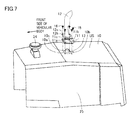
Fig. 7 is an exploded perspective view showing members around the exhaust pipe disassembled and the exhaust pipe partially exploded. -
Fig. 8 is a schematic perspective view for illustrating a method for manufacturing a wheel loader in one embodiment of the present invention, showing the top with a first hole, and the tail pipe through the first hole. -
Fig. 9 is a schematic perspective view for illustrating the method for manufacturing a wheel loader in one embodiment of the present invention, showing attaching the exhaust pipe, shown partially exploded, to the top with reference to the plate. -
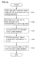
Fig. 10 is a flow chart of the service. -
Fig. 11 is a side view schematically showing a rear body with a side door open in one embodiment of the present invention. - Hereinafter, the present invention in an embodiment will be described with reference to the drawings.
- Initially will be described a configuration of a work vehicle in one embodiment of the present invention. While hereinafter will be described a wheel loader that is one example of a work vehicle to which the idea of the present invention is applicable, the present invention is also applicable to bulldozers and the like.
- With reference to
Fig. 1 , the present embodiment provides awheel loader 1 having arear body 2, afront frame 3, and a work implement 4 as main components.Front frame 3 has opposite side portions each having afront wheel 5a attached thereto andrear body 2 has opposite side portions each having arear wheel 5b attached thereto. -
Rear body 2 andfront frame 3 are attached by a center pin (not shown) to be capable of swinging rightward and leftward and thus configure an articulated structure. More specifically,rear body 2 andfront frame 3 are coupled by a pair of right and left steering cylinders (not shown) extended and retracted to allowrear body 2 andfront frame 3 to swing rightward and leftward around the center pin and thus be steered.Rear body 2 andfront frame 3 configure a vehicular body ofwheel loader 1. - In front of
front frame 3,work implement 4 is attached.Work implement 4 has aboom 4a having a proximal end attached tofront frame 3 to swing as desired, and abucket 4b attached to a distal end ofboom 4a to swing as desired.Front frame 3 andboom 4a are coupled by a pair ofboom cylinders 4c extended and retracted to causeboom 4a to swing. - Furthermore, work implement 4 has a
bell crank 4d supported substantially at its center byboom 4a to swing as desired, abucket cylinder 4e that couples a proximal end ofbell crank 4d andfront frame 3 together, and alink 4f that couples a distal end ofbell crank 4d andbucket 4b together.Bucket cylinder 4e is extended and retracted to causebucket 4b to swing. - Behind
rear body 2 is disposed anengine compartment 6, and in front ofengine compartment 6 is disposed ahydraulic oil tank 7. In front ofhydraulic oil tank 7 is disposed acab 8 in which an operator operateswheel loader 1. Note thatwheel loader 1 has front and rear, and right and left sides, which are indicated with reference to the operator seated incab 8. -
Rear body 2 has a top side having a top 10.Top 10 has an inclined upper surface US that is lower toward the vehicular body's rear side whenwheel loader 1 is placed on a horizontal ground surface G. Anexhaust pipe 12 is attached to top 10 at inclined upper surface US viaplate 11. - With reference to
Fig. 1 and Fig. 2 ,engine compartment 6 has accommodated therein a portion of atail pipe 13, anengine 21, an exhaust gas processing device (a diesel particulate filter (DPF)) 22, and asuction system filter 23. Exhaustgas processing device 22 andsuction system filter 23 are connected toengine 21.Tail pipe 13 is connected to exhaustgas processing device 22. Acap 24 is connected tosuction system filter 23.Cap 24 is disposed closer to the vehicular body's front side thanexhaust pipe 12.Rear body 2 has a side surface provided with aside door 25. - With reference to
Fig. 3 ,plate 11 is disposed on top 10 andexhaust pipe 12 is disposed onplate 11.Top 10 has afirst hole 10a and aninsertion hole 10b.Plate 11 has asecond hole 11a.Plate 11 is attached to top 10 to havesecond hole 11a in alignment withfirst hole 10a. -
Exhaust pipe 12 is generally cylindrical in geometry.Exhaust pipe 12 has aninternal path 12a.Exhaust pipe 12 has a lower end with aflange 12b projecting outward.Flange 12b abuts againstplate 11.Exhaust pipe 12 is attached to plate 11 in alignment withfirst hole 10a andsecond hole 11a.Tail pipe 13 is generally cylindrical in geometry.Tail pipe 13 has a portion positioned infirst hole 10a andsecond hole 11a.Tail pipe 13 has an end disposed ininternal path 12a ofexhaust pipe 12. - With reference to
Fig. 3 and Fig. 4 , afirst screw member 15 attachesplate 11 totop 10. Asecond screw member 16 attachesexhaust pipe 12 to top 10 and in doing sosecond screw member 16 is not screwed to plate 11. -
Exhaust pipe 12 hasflange 12b in the form of a rectangle as seen in a plane.Exhaust pipe 12 hasflange 12b with aninsertion hole 12c therethrough for receiving and passingsecond screw member 16 therethrough.Insertion hole 12c is provided throughflange 12b at four corners. - With reference to
Fig. 5 ,plate 11, as seen in a plane, has arectangular portion 101 and aprojection 102 projecting outward arcuately from a long side ofrectangular portion 101.Plate 11 has aninsertion hole 11b for receiving and passingfirst screw member 15 therethrough.Insertion hole 11b is provided throughprojection 102.Plate 11 has aninsertion hole 11c for receiving and passingsecond screw member 16 therethrough.Insertion hole 11c is provided throughrectangular portion 101 at four corners. - One
insertion hole 11b is provided at a position at whichflange 12b does not overlap the head offirst screw member 15.Insertion hole 11b is provided on a centerline CL ofplate 11.Plate 11 has afirst side 111 opposite toinsertion hole 11b withsecond hole 11a posed therebetween and has asecond side 112 and athird side 113 adjacent tofirst side 111 at its opposite ends, respectively. - As shown in
Fig. 3 to Fig. 5 ,first screw member 15 is inserted throughinsertion hole 11b ofplate 11. Awasher 15a is disposed between the head offirst screw member 15 andplate 11. Anut 15b is screwed to the shank offirst screw member 15 on a lower surface oftop 10. Thefirst screw member 15 shank has a diameter smaller in dimension than that ofinsertion hole 10b of top 10 and that ofinsertion hole 11b ofplate 11. Accordingly,plate 11 can be moved withfirst screw member 15 inserted throughinsertion hole 11b ofplate 11. Note thatnut 15b is welded and thus secured to a back surface oftop 10. -
Second screw member 16 is inserted throughinsertion hole 10c of top 10,insertion hole 11c ofplate 11, andinsertion hole 12c offlange 12b. Awasher 16a is disposed between the head ofsecond screw member 16 andflange 12b. Anut 16b is screwed to the shank ofsecond screw member 16 on a lower surface oftop 10. Thesecond screw member 16 shank has a diameter smaller in dimension than that ofinsertion hole 10c of top 10 and those ofinsertion hole 11c ofplate 11 andinsertion hole 12c offlange 12b. Accordingly,exhaust pipe 12 can be moved withsecond screw member 16 inserted throughinsertion holes nut 16b is welded and thus secured to the back surface oftop 10. -
Flange 12b in the form of a rectangle has three sides aligned withfirst side 111,second side 112, andthird side 113 ofplate 11. Theplate 11second hole 11a andtail pipe 13 are disposed concentrically. Thus,tail pipe 13 andexhaust pipe 12 are disposed concentrically. -
Plate 11 andexhaust pipe 12 are attached to top 10 at inclined upper surface US that is lower toward the vehicular body's rear side. In that case,exhaust pipe 12 andtail pipe 13 being concentric means thatexhaust pipe 12 andtail pipe 13 are concentric whenexhaust pipe 12 andtail pipe 13 are seen in a direction in whichexhaust pipe 12 andtail pipe 13 extend. - Note that top 10 that is inclined allows better visibility. On the other hand, when
exhaust pipe 12 is disposed at inclined upper surface US, it is difficult to disposeexhaust pipe 12 andtail pipe 13 concentrically. In the present embodiment,plate 11 is used as a reference in attachingexhaust pipe 12 to top 10, and this facilitates disposingexhaust pipe 12 andtail pipe 13 concentrically while attachingexhaust pipe 12 to inclined upper surface US. - With reference to
Fig. 6 , thefirst screw member 15 shank andinsertion hole 11b, as seen radially, have an outer diameter and an inner diameter, respectively, with gaps L1 and L2 therebetween. A total of gaps L1 and L2 will serve a difference between the diameter offirst screw member 15 and the diameter ofinsertion hole 11b.Exhaust pipe 12 andtail pipe 13, as seen radially, have gaps L3 and L4 therebetween. A total of gaps L3 and L4 will serve as a difference between a diameter ofinternal path 12a ofexhaust pipe 12 and an outer diameter oftail pipe 13. - In the present embodiment,
insertion hole 11b andfirst screw member 15 have a difference in diameter having a dimension that can absorb a difference between the outer diameter oftail pipe 13 and the diameter ofinternal path 12a ofexhaust pipe 12. The total of gaps L1 and L2 and the total of gaps L3 and L4 are in effect dimensionally equal or the former is dimensionally slightly larger than the latter. - With reference to
Fig. 7 ,plate 11 is disposed between top 10 andflange 12b.Plate 11 is used as a reference in attachingexhaust pipe 12 atflange 12b to top 10. Theplate 11first side 111,second side 112, and third side 113 (seeFig. 5 ) andrectangular flange 12b's three sides are aligned to disposeplate 11 andflange 12b to overlap each other. - The above described service is provided in a procedure, as will be described hereinafter with reference to the drawings.
Fig. 10 is a flow chart of the procedure. - With reference to
Fig. 8 , top 10 hasfirst hole 10a,insertion hole 10b, andinsertion hole 10c formed therethrough. In Step S101,tail pipe 13 is passed throughfirst hole 10a of top 10, and top 10 is attached to the vehicular body. - With reference to
Fig. 8 ,plate 11 hassecond hole 11a,insertion hole 11b, andinsertion hole 11c formed therethrough. In Step S102,plate 11 is positioned on top 10 to havesecond hole 11a concentrically withtail pipe 13. - In Step S103,
first screw member 15 is used to secureplate 11 totop 10.First screw member 15 is inserted throughinsertion hole 10b of top 10 andinsertion hole 11b ofplate 11 viawasher 15a, and screwed tonut 15b (not shown) secured to the back surface oftop 10. - In Step S104,
exhaust pipe 12 hasflange 12b positioned with reference toplate 11. In doing so,flange 12b in the form of a rectangle has three sides aligned withfirst side 111,second side 112, andthird side 113 ofplate 11.Exhaust pipe 12 is thus positioned concentrically withtail pipe 13 viaplate 11. - In Step S105,
second screw member 15 is used to secureexhaust pipe 12 totop 10. With reference toFig. 9 ,first screw member 15 is inserted throughinsertion hole 10c of top 10,insertion hole 11c ofplate 11 andinsertion hole 12c offlange 12b viawasher 15a, and screwed tonut 16b (not shown) secured to the back surface oftop 10.Second screw member 16 thus attachesflange 12b to top 10 and in doing sosecond screw member 16 is not screwed to plate 11. Then,exhaust pipe 12 is attached to top 10 concentrically withtail pipe 13. - The present embodiment provides a function and an effect, as follows:
- The present embodiment provides
wheel loader 1 that can eliminate the necessity of opening a side door and requiring two servicepersons to work together to position an exhaust pipe, asplate 11 can serve as a reference to facilitate disposingexhaust pipe 12 andtail pipe 13 concentrically. - The present embodiment provides
wheel loader 1 such that, as shown inFig. 8 andFig. 9 ,plate 11 that is disposed between top 10 andflange 12b serves as a reference in attachingflange 12b to top 10, so that whilesecond hole 11a andtail pipe 13 are positioned concentrically,plate 11 is used as a reference in attachingflange 12b to top 10 to facilitate disposingexhaust pipe 12 andtail pipe 13 concentrically. Furthermore, usingplate 11 as a reference in attachingflange 12b to top 10 contributes to better workability in disposingexhaust pipe 12 andtail pipe 13 concentrically. - The present embodiment provides
wheel loader 1 withsecond hole 11a andtail pipe 13 disposed concentrically. This allowsplate 11 to serve as a reference in attachingflange 12b to top 10 to facilitate disposingexhaust pipe 12 andtail pipe 13 concentrically. - The present embodiment provides
wheel loader 1 such thatplate 11 andexhaust pipe 12 are attached to top 10 at inclined upper surface US.Plate 11 can thus also serve as a reference to allowexhaust pipe 12 to be attached to inclined upper surface US concentrically withtail pipe 13. - The present embodiment provides
wheel loader 1 such thatfirst screw member 15 attachesplate 11 to top 10 andsecond screw member 16 attachesexhaust pipe 12 to top 10 and in doing sosecond screw member 16 is not screwed to plate 11. This allowsexhaust pipe 12 to be moved relative to plate 11 and thus attached to top 10.Exhaust pipe 12 can thus be easily disposed concentrically withtail pipe 13 with reference toplate 11. - The present embodiment provides
wheel loader 1 such thatinsertion hole 11 b andfirst screw member 15 have a difference in diameter having a dimension that can absorb a difference between the outer diameter oftail pipe 13 and the diameter ofinternal path 12a ofexhaust pipe 12.Exhaust pipe 12 can be moved withfirst screw member 15 inserted throughinsertion hole 11b, andtail pipe 13 andexhaust pipe 12 can thus be disposed concentrically. - The present embodiment provides a method for manufacturing
wheel loader 1, as follows:plate 11 is positioned on top 10 to havesecond hole 11a concentrically withtail pipe 13 andexhaust pipe 12 hasflange 12b attached to top 10 with reference to plate 11 that has been positioned on top 10 to facilitate disposingexhaust pipe 12 andtail pipe 13 concentrically. Furthermore, usingplate 11 as a reference in attachingflange 12b to top 10 contributes to better workability in disposingexhaust pipe 12 andtail pipe 13 concentrically. - The present embodiment provides the method for manufacturing
wheel loader 1, as follows:flange 12b is aligned withplate 11 in geometry and thus attached to top 10.Flange 12b can be easily positioned onplate 11. - The present embodiment provides the method for manufacturing
wheel loader 1, as follows:plate 11 is positioned on top 10 byfirst screw member 15 andsecond screw member 16 is used to attachflange 12b to top 10 and in doing sosecond screw member 16 is not screwed to plate 11. This allowsexhaust pipe 12 to be moved relative to plate 11 and thus registered, and then attached to top 10.Exhaust pipe 12 can thus be easily disposed concentrically withtail pipe 13 with reference toplate 11. - Note that while in the above
description tail pipe 13 is connected to exhaustgas processing device 22,tail pipe 13 may be connected to a muffler. Furthermore, while in the above description exhaustgas processing device 22 is a DPF, it may be a device which removes nitrogen oxide and/or the like. - While in the
above description flange 12b in the form of a rectangle has three sides aligned withfirst side 111,second side 112, andthird side 113 ofplate 11,flange 12b in the form of the rectangle may have two sides aligned with any offirst side 111,second side 112, andthird side 113. Furthermore, ifplate 11 is curved in geometry,flange 12b can be registered along the curved geometry ofplate 11. - Furthermore, while in the
above description flange 12b is geometrically aligned withplate 11, it may not be done so. More specifically,plate 11 may be provided with a marking andflange 12b may be disposed in alignment therewith. - Furthermore, while in the
above description plate 11 is disposed between top 10 andflange 12b andflange 12b is thus attached to top 10,plate 11 may not be disposed. More specifically,plate 11 andflange 12b may be matched in geometry andplate 11 may be used as a reference to provide top 10 with a marking which may in turn be used as a reference in settingflange 12b. - It should be understood that the embodiment disclosed herein is illustrative and non-restrictive in any respect. The scope of the present invention is defined by the terms of the claims, rather than the description above, and is intended to include any modifications within the scope and meaning equivalent to the terms of the claims.
- The present invention is advantageously applicable to work vehicles having an exhaust pipe and a method for manufacturing the same.
- 1: wheel loader, 2: rear body; 3: front frame; 4: work implement; 5a: front wheel; 5b: rear wheel; 6: engine compartment; 7: hydraulic oil tank; 8: cab; 10: top; 10a: first hole; 10b, 10c, 11b, 11c, 12, 12c: insertion hole; 11: plate; 11a: second hole; 12: exhaust pipe; 12a: internal path; 12b: flange; 13: tail pipe; 15: first screw member; 15a, 16a: washer; 15b, 16b: nut; 16: second screw member; 21: engine; 22: exhaust gas processing device; 23: suction system filter; 24: cap; 25: side door; 101: rectangular portion; 102: projection; G: ground surface; US: inclined upper surface.
Claims (8)
- A work vehicle comprising:a top having a first hole;a plate having a second hole and attached to said top with said second hole in alignment with said first hole;an exhaust pipe having an internal path and a flange projecting outward and abutting against and thus attached to said plate; anda tail pipe having a portion positioned in said first and second holes, and an end in said internal path of said exhaust pipe,said plate being disposed between said top and said flange and serving as a reference in attaching said flange to said top.
- The work vehicle according to claim 1, wherein said second hole and said tail pipe are disposed concentrically.
- The work vehicle according to claim 1 or 2, wherein:said top has an upper surface inclined with the work vehicle placed on a horizontal ground surface; andsaid plate and said exhaust pipe are attached to said upper surface inclined.
- The work vehicle according to any of claims 1-3, further comprising first and second screw members, wherein:said first screw member attaches said plate to said top; andsaid second screw member attaches said exhaust pipe to said top and in doing so said second screw member is not screwed to said plate.
- The work vehicle according to claim 4, wherein:said plate includes an insertion hole for receiving and passing said first screw member therethrough; andsaid insertion hole and said first screw member have diameters, respectively, having a difference that is equal to a difference between an outer diameter of said tail pipe and a diameter of said internal path of said exhaust pipe.
- A method for manufacturing a work vehicle, comprising the steps of:disposing a top having a first hole and a tail pipe to pass said tail pipe through said first hole;positioning a plate having a second hole on said top to have said second hole concentrically with said tail pipe; andattaching an exhaust pipe having an outwardly projecting flange to said top at said flange with reference to said plate positioned on said top.
- The method for manufacturing a work vehicle according to claim 6,
wherein in the step of attaching, said flange is aligned with said plate in geometry and thus attached to said top. - The method for manufacturing a work vehicle according to claim 6 or 7, wherein:in the step of positioning, said plate is positioned on said top by a first screw member; andin the step of attaching, a second screw member is used to attach said flange to said top and in doing so said second screw member is not screwed to said plate.
Applications Claiming Priority (2)
| Application Number | Priority Date | Filing Date | Title |
|---|---|---|---|
| JP2012148819A JP5315442B1 (en) | 2012-07-02 | 2012-07-02 | Work vehicle and method of manufacturing work vehicle |
| PCT/JP2012/075499 WO2014006769A1 (en) | 2012-07-02 | 2012-10-02 | Working vehicle and method for manufacturing working vehicle |
Publications (3)
| Publication Number | Publication Date |
|---|---|
| EP2868508A1 true EP2868508A1 (en) | 2015-05-06 |
| EP2868508A4 EP2868508A4 (en) | 2016-03-16 |
| EP2868508B1 EP2868508B1 (en) | 2017-09-20 |
Family
ID=49595746
Family Applications (1)
| Application Number | Title | Priority Date | Filing Date |
|---|---|---|---|
| EP12823069.5A Not-in-force EP2868508B1 (en) | 2012-07-02 | 2012-10-02 | Working vehicle and method for manufacturing working vehicle |
Country Status (5)
| Country | Link |
|---|---|
| US (1) | US8931266B2 (en) |
| EP (1) | EP2868508B1 (en) |
| JP (1) | JP5315442B1 (en) |
| CN (1) | CN103648820B (en) |
| WO (1) | WO2014006769A1 (en) |
Families Citing this family (8)
| Publication number | Priority date | Publication date | Assignee | Title |
|---|---|---|---|---|
| GB2515450B (en) * | 2013-03-18 | 2017-03-22 | Alexander Dennis Ltd | Passenger service vehicle |
| US9302579B2 (en) * | 2014-05-20 | 2016-04-05 | Deere & Company | Flush mounted tractor exhaust outlet |
| WO2015079749A1 (en) * | 2014-08-19 | 2015-06-04 | 株式会社小松製作所 | Work vehicle |
| WO2018070997A1 (en) * | 2016-10-11 | 2018-04-19 | Halliburton Energy Services, Inc. | Well site noise control |
| TR201618056A2 (en) * | 2016-12-07 | 2018-06-21 | Ford Otomotiv Sanayi As | MODULAR EXHAUST EXIT PIPE |
| JP6765994B2 (en) * | 2017-03-08 | 2020-10-07 | 住友建機株式会社 | Excavator |
| US11732633B2 (en) * | 2022-01-04 | 2023-08-22 | Caterpillar Inc. | Exhaust discharge system |
| US12480432B2 (en) | 2023-09-08 | 2025-11-25 | Thermo King Llc | Remote diesel oxidation catalyst for a prime mover of a transport power system |
Family Cites Families (17)
| Publication number | Priority date | Publication date | Assignee | Title |
|---|---|---|---|---|
| US3110239A (en) * | 1960-11-28 | 1963-11-12 | Jr George Dashwood | Cap for vertical exhaust pipe of internal combustion engine |
| US4133547A (en) * | 1977-07-11 | 1979-01-09 | Massey-Ferguson Inc. | Engine componentry |
| JPS5884318U (en) * | 1981-12-01 | 1983-06-08 | 富士ロビン株式会社 | Exhaust system in the muffler section of mobile agricultural machinery |
| US4903484A (en) * | 1989-05-08 | 1990-02-27 | Yates Clyde I | Exhaust dissipator and deflector |
| US5170020A (en) * | 1991-03-05 | 1992-12-08 | Deere & Company | Rainproof exhaust pipe |
| JP2000213345A (en) | 1999-01-21 | 2000-08-02 | Komatsu Ltd | Exhaust muffler mounting device |
| US7007720B1 (en) * | 2000-04-04 | 2006-03-07 | Lacks Industries, Inc. | Exhaust tip |
| JP2002174108A (en) | 2000-12-07 | 2002-06-21 | Hitachi Constr Mach Co Ltd | Exhaust pipe structure of work vehicle |
| JP3084366U (en) * | 2001-08-29 | 2002-03-22 | 株式会社アイチコーポレーション | Pipe through hole shielding device |
| JP4135099B2 (en) * | 2004-03-15 | 2008-08-20 | コベルコ建機株式会社 | Engine exhaust system for construction machinery |
| DE112005002903B4 (en) * | 2004-11-25 | 2010-01-28 | Komatsu Ltd. | Exhaust gas purification device for internal combustion engine |
| CN201225192Y (en) * | 2008-07-22 | 2009-04-22 | 戴晨矛 | Adjustable automobile exhaust tube |
| JP5311551B2 (en) | 2008-09-08 | 2013-10-09 | 株式会社小松製作所 | Wheel loader |
| JP5192328B2 (en) | 2008-09-08 | 2013-05-08 | 株式会社小松製作所 | Work vehicle |
| KR101026190B1 (en) * | 2009-01-23 | 2011-03-31 | 볼보 컨스트럭션 이큅먼트 에이비 | Superheater gas temperature reduction device in engine room |
| JP5356349B2 (en) * | 2010-09-30 | 2013-12-04 | 日立建機株式会社 | Exhaust equipment for construction machinery |
| US8720195B2 (en) * | 2012-02-14 | 2014-05-13 | Deere & Company | Exhaust assembly |
-
2012
- 2012-07-02 JP JP2012148819A patent/JP5315442B1/en not_active Expired - Fee Related
- 2012-10-02 CN CN201280002457.5A patent/CN103648820B/en not_active Expired - Fee Related
- 2012-10-02 US US13/814,011 patent/US8931266B2/en not_active Expired - Fee Related
- 2012-10-02 WO PCT/JP2012/075499 patent/WO2014006769A1/en not_active Ceased
- 2012-10-02 EP EP12823069.5A patent/EP2868508B1/en not_active Not-in-force
Also Published As
| Publication number | Publication date |
|---|---|
| JP5315442B1 (en) | 2013-10-16 |
| JP2014009663A (en) | 2014-01-20 |
| EP2868508A4 (en) | 2016-03-16 |
| EP2868508B1 (en) | 2017-09-20 |
| US20140182730A1 (en) | 2014-07-03 |
| CN103648820A (en) | 2014-03-19 |
| US8931266B2 (en) | 2015-01-13 |
| WO2014006769A1 (en) | 2014-01-09 |
| CN103648820B (en) | 2015-04-15 |
Similar Documents
| Publication | Publication Date | Title |
|---|---|---|
| EP2868508B1 (en) | Working vehicle and method for manufacturing working vehicle | |
| US9061582B2 (en) | Hydraulic excavator | |
| JP5130410B1 (en) | Work vehicle | |
| US20140299401A1 (en) | Hydraulic excavator | |
| US9016426B2 (en) | Exhaust treatment unit | |
| US8955638B2 (en) | Hydraulic excavator | |
| CN103946503B (en) | hydraulic excavator | |
| US20140305110A1 (en) | Exhaust treatment unit and method of attaching and detaching exhaust treatment unit | |
| US7419064B2 (en) | Working machine | |
| CN103906906B (en) | exhaust treatment unit | |
| US20140250870A1 (en) | Exhaust treatment unit | |
| CN104903518A (en) | Work vehicle and operator protective guard | |
| EP3178679B1 (en) | Work vehicle, method for operating tow apparatus, and method for assembling tow apparatus | |
| US20160265193A1 (en) | Working vehicle | |
| US20130161112A1 (en) | Modular exhaust carrier | |
| US20150144415A1 (en) | Vehicle component enclosure | |
| US9670647B2 (en) | Work vehicle | |
| CN107107964A (en) | The hood of tractor | |
| US20060254096A1 (en) | Quick attach coupling device | |
| JP5919441B2 (en) | Excavator | |
| US12180684B2 (en) | Pipe protection unit in work machine | |
| JP2017106178A (en) | Front loader and working vehicle | |
| US9555842B1 (en) | Adapter bracket assembly configured to adapt a utility vehicle for use with a different utility component | |
| JP2013151828A (en) | Construction machine | |
| JP6765994B2 (en) | Excavator |
Legal Events
| Date | Code | Title | Description |
|---|---|---|---|
| PUAI | Public reference made under article 153(3) epc to a published international application that has entered the european phase |
Free format text: ORIGINAL CODE: 0009012 |
|
| 17P | Request for examination filed |
Effective date: 20130218 |
|
| AK | Designated contracting states |
Kind code of ref document: A1 Designated state(s): AL AT BE BG CH CY CZ DE DK EE ES FI FR GB GR HR HU IE IS IT LI LT LU LV MC MK MT NL NO PL PT RO RS SE SI SK SM TR |
|
| AX | Request for extension of the european patent |
Extension state: BA ME |
|
| DAX | Request for extension of the european patent (deleted) | ||
| RA4 | Supplementary search report drawn up and despatched (corrected) |
Effective date: 20160211 |
|
| RIC1 | Information provided on ipc code assigned before grant |
Ipc: B60K 13/04 20060101AFI20160205BHEP Ipc: F01N 13/08 20100101ALI20160205BHEP Ipc: E02F 9/00 20060101ALI20160205BHEP |
|
| 17Q | First examination report despatched |
Effective date: 20161122 |
|
| GRAP | Despatch of communication of intention to grant a patent |
Free format text: ORIGINAL CODE: EPIDOSNIGR1 |
|
| INTG | Intention to grant announced |
Effective date: 20170524 |
|
| GRAS | Grant fee paid |
Free format text: ORIGINAL CODE: EPIDOSNIGR3 |
|
| GRAA | (expected) grant |
Free format text: ORIGINAL CODE: 0009210 |
|
| AK | Designated contracting states |
Kind code of ref document: B1 Designated state(s): AL AT BE BG CH CY CZ DE DK EE ES FI FR GB GR HR HU IE IS IT LI LT LU LV MC MK MT NL NO PL PT RO RS SE SI SK SM TR |
|
| REG | Reference to a national code |
Ref country code: GB Ref legal event code: FG4D |
|
| REG | Reference to a national code |
Ref country code: CH Ref legal event code: EP |
|
| REG | Reference to a national code |
Ref country code: AT Ref legal event code: REF Ref document number: 929852 Country of ref document: AT Kind code of ref document: T Effective date: 20171015 |
|
| REG | Reference to a national code |
Ref country code: IE Ref legal event code: FG4D |
|
| REG | Reference to a national code |
Ref country code: DE Ref legal event code: R096 Ref document number: 602012037644 Country of ref document: DE |
|
| REG | Reference to a national code |
Ref country code: SE Ref legal event code: TRGR |
|
| REG | Reference to a national code |
Ref country code: NL Ref legal event code: MP Effective date: 20170920 |
|
| PG25 | Lapsed in a contracting state [announced via postgrant information from national office to epo] |
Ref country code: FI Free format text: LAPSE BECAUSE OF FAILURE TO SUBMIT A TRANSLATION OF THE DESCRIPTION OR TO PAY THE FEE WITHIN THE PRESCRIBED TIME-LIMIT Effective date: 20170920 Ref country code: HR Free format text: LAPSE BECAUSE OF FAILURE TO SUBMIT A TRANSLATION OF THE DESCRIPTION OR TO PAY THE FEE WITHIN THE PRESCRIBED TIME-LIMIT Effective date: 20170920 Ref country code: NO Free format text: LAPSE BECAUSE OF FAILURE TO SUBMIT A TRANSLATION OF THE DESCRIPTION OR TO PAY THE FEE WITHIN THE PRESCRIBED TIME-LIMIT Effective date: 20171220 Ref country code: LT Free format text: LAPSE BECAUSE OF FAILURE TO SUBMIT A TRANSLATION OF THE DESCRIPTION OR TO PAY THE FEE WITHIN THE PRESCRIBED TIME-LIMIT Effective date: 20170920 |
|
| REG | Reference to a national code |
Ref country code: LT Ref legal event code: MG4D |
|
| REG | Reference to a national code |
Ref country code: AT Ref legal event code: MK05 Ref document number: 929852 Country of ref document: AT Kind code of ref document: T Effective date: 20170920 |
|
| PG25 | Lapsed in a contracting state [announced via postgrant information from national office to epo] |
Ref country code: GR Free format text: LAPSE BECAUSE OF FAILURE TO SUBMIT A TRANSLATION OF THE DESCRIPTION OR TO PAY THE FEE WITHIN THE PRESCRIBED TIME-LIMIT Effective date: 20171221 Ref country code: RS Free format text: LAPSE BECAUSE OF FAILURE TO SUBMIT A TRANSLATION OF THE DESCRIPTION OR TO PAY THE FEE WITHIN THE PRESCRIBED TIME-LIMIT Effective date: 20170920 Ref country code: LV Free format text: LAPSE BECAUSE OF FAILURE TO SUBMIT A TRANSLATION OF THE DESCRIPTION OR TO PAY THE FEE WITHIN THE PRESCRIBED TIME-LIMIT Effective date: 20170920 Ref country code: BG Free format text: LAPSE BECAUSE OF FAILURE TO SUBMIT A TRANSLATION OF THE DESCRIPTION OR TO PAY THE FEE WITHIN THE PRESCRIBED TIME-LIMIT Effective date: 20171220 |
|
| PG25 | Lapsed in a contracting state [announced via postgrant information from national office to epo] |
Ref country code: NL Free format text: LAPSE BECAUSE OF FAILURE TO SUBMIT A TRANSLATION OF THE DESCRIPTION OR TO PAY THE FEE WITHIN THE PRESCRIBED TIME-LIMIT Effective date: 20170920 |
|
| PG25 | Lapsed in a contracting state [announced via postgrant information from national office to epo] |
Ref country code: PL Free format text: LAPSE BECAUSE OF FAILURE TO SUBMIT A TRANSLATION OF THE DESCRIPTION OR TO PAY THE FEE WITHIN THE PRESCRIBED TIME-LIMIT Effective date: 20170920 Ref country code: RO Free format text: LAPSE BECAUSE OF FAILURE TO SUBMIT A TRANSLATION OF THE DESCRIPTION OR TO PAY THE FEE WITHIN THE PRESCRIBED TIME-LIMIT Effective date: 20170920 Ref country code: CZ Free format text: LAPSE BECAUSE OF FAILURE TO SUBMIT A TRANSLATION OF THE DESCRIPTION OR TO PAY THE FEE WITHIN THE PRESCRIBED TIME-LIMIT Effective date: 20170920 Ref country code: ES Free format text: LAPSE BECAUSE OF FAILURE TO SUBMIT A TRANSLATION OF THE DESCRIPTION OR TO PAY THE FEE WITHIN THE PRESCRIBED TIME-LIMIT Effective date: 20170920 |
|
| PG25 | Lapsed in a contracting state [announced via postgrant information from national office to epo] |
Ref country code: IS Free format text: LAPSE BECAUSE OF FAILURE TO SUBMIT A TRANSLATION OF THE DESCRIPTION OR TO PAY THE FEE WITHIN THE PRESCRIBED TIME-LIMIT Effective date: 20180120 Ref country code: IT Free format text: LAPSE BECAUSE OF FAILURE TO SUBMIT A TRANSLATION OF THE DESCRIPTION OR TO PAY THE FEE WITHIN THE PRESCRIBED TIME-LIMIT Effective date: 20170920 Ref country code: AT Free format text: LAPSE BECAUSE OF FAILURE TO SUBMIT A TRANSLATION OF THE DESCRIPTION OR TO PAY THE FEE WITHIN THE PRESCRIBED TIME-LIMIT Effective date: 20170920 Ref country code: SM Free format text: LAPSE BECAUSE OF FAILURE TO SUBMIT A TRANSLATION OF THE DESCRIPTION OR TO PAY THE FEE WITHIN THE PRESCRIBED TIME-LIMIT Effective date: 20170920 Ref country code: SK Free format text: LAPSE BECAUSE OF FAILURE TO SUBMIT A TRANSLATION OF THE DESCRIPTION OR TO PAY THE FEE WITHIN THE PRESCRIBED TIME-LIMIT Effective date: 20170920 Ref country code: EE Free format text: LAPSE BECAUSE OF FAILURE TO SUBMIT A TRANSLATION OF THE DESCRIPTION OR TO PAY THE FEE WITHIN THE PRESCRIBED TIME-LIMIT Effective date: 20170920 |
|
| REG | Reference to a national code |
Ref country code: CH Ref legal event code: PL |
|
| REG | Reference to a national code |
Ref country code: DE Ref legal event code: R097 Ref document number: 602012037644 Country of ref document: DE |
|
| PG25 | Lapsed in a contracting state [announced via postgrant information from national office to epo] |
Ref country code: MC Free format text: LAPSE BECAUSE OF FAILURE TO SUBMIT A TRANSLATION OF THE DESCRIPTION OR TO PAY THE FEE WITHIN THE PRESCRIBED TIME-LIMIT Effective date: 20170920 |
|
| REG | Reference to a national code |
Ref country code: IE Ref legal event code: MM4A |
|
| PLBE | No opposition filed within time limit |
Free format text: ORIGINAL CODE: 0009261 |
|
| REG | Reference to a national code |
Ref country code: FR Ref legal event code: ST Effective date: 20180629 |
|
| STAA | Information on the status of an ep patent application or granted ep patent |
Free format text: STATUS: NO OPPOSITION FILED WITHIN TIME LIMIT |
|
| PG25 | Lapsed in a contracting state [announced via postgrant information from national office to epo] |
Ref country code: LI Free format text: LAPSE BECAUSE OF NON-PAYMENT OF DUE FEES Effective date: 20171031 Ref country code: LU Free format text: LAPSE BECAUSE OF NON-PAYMENT OF DUE FEES Effective date: 20171002 Ref country code: CH Free format text: LAPSE BECAUSE OF NON-PAYMENT OF DUE FEES Effective date: 20171031 Ref country code: DK Free format text: LAPSE BECAUSE OF FAILURE TO SUBMIT A TRANSLATION OF THE DESCRIPTION OR TO PAY THE FEE WITHIN THE PRESCRIBED TIME-LIMIT Effective date: 20170920 |
|
| REG | Reference to a national code |
Ref country code: BE Ref legal event code: MM Effective date: 20171031 |
|
| 26N | No opposition filed |
Effective date: 20180621 |
|
| GBPC | Gb: european patent ceased through non-payment of renewal fee |
Effective date: 20171220 |
|
| PG25 | Lapsed in a contracting state [announced via postgrant information from national office to epo] |
Ref country code: FR Free format text: LAPSE BECAUSE OF NON-PAYMENT OF DUE FEES Effective date: 20171120 Ref country code: BE Free format text: LAPSE BECAUSE OF NON-PAYMENT OF DUE FEES Effective date: 20171031 |
|
| PG25 | Lapsed in a contracting state [announced via postgrant information from national office to epo] |
Ref country code: MT Free format text: LAPSE BECAUSE OF NON-PAYMENT OF DUE FEES Effective date: 20171002 |
|
| PG25 | Lapsed in a contracting state [announced via postgrant information from national office to epo] |
Ref country code: IE Free format text: LAPSE BECAUSE OF NON-PAYMENT OF DUE FEES Effective date: 20171002 |
|
| PG25 | Lapsed in a contracting state [announced via postgrant information from national office to epo] |
Ref country code: SI Free format text: LAPSE BECAUSE OF FAILURE TO SUBMIT A TRANSLATION OF THE DESCRIPTION OR TO PAY THE FEE WITHIN THE PRESCRIBED TIME-LIMIT Effective date: 20170920 Ref country code: GB Free format text: LAPSE BECAUSE OF NON-PAYMENT OF DUE FEES Effective date: 20171220 |
|
| PG25 | Lapsed in a contracting state [announced via postgrant information from national office to epo] |
Ref country code: HU Free format text: LAPSE BECAUSE OF FAILURE TO SUBMIT A TRANSLATION OF THE DESCRIPTION OR TO PAY THE FEE WITHIN THE PRESCRIBED TIME-LIMIT; INVALID AB INITIO Effective date: 20121002 |
|
| PG25 | Lapsed in a contracting state [announced via postgrant information from national office to epo] |
Ref country code: CY Free format text: LAPSE BECAUSE OF FAILURE TO SUBMIT A TRANSLATION OF THE DESCRIPTION OR TO PAY THE FEE WITHIN THE PRESCRIBED TIME-LIMIT Effective date: 20170920 |
|
| PG25 | Lapsed in a contracting state [announced via postgrant information from national office to epo] |
Ref country code: MK Free format text: LAPSE BECAUSE OF FAILURE TO SUBMIT A TRANSLATION OF THE DESCRIPTION OR TO PAY THE FEE WITHIN THE PRESCRIBED TIME-LIMIT Effective date: 20170920 |
|
| PG25 | Lapsed in a contracting state [announced via postgrant information from national office to epo] |
Ref country code: TR Free format text: LAPSE BECAUSE OF FAILURE TO SUBMIT A TRANSLATION OF THE DESCRIPTION OR TO PAY THE FEE WITHIN THE PRESCRIBED TIME-LIMIT Effective date: 20170920 |
|
| PG25 | Lapsed in a contracting state [announced via postgrant information from national office to epo] |
Ref country code: PT Free format text: LAPSE BECAUSE OF FAILURE TO SUBMIT A TRANSLATION OF THE DESCRIPTION OR TO PAY THE FEE WITHIN THE PRESCRIBED TIME-LIMIT Effective date: 20170920 |
|
| PG25 | Lapsed in a contracting state [announced via postgrant information from national office to epo] |
Ref country code: AL Free format text: LAPSE BECAUSE OF FAILURE TO SUBMIT A TRANSLATION OF THE DESCRIPTION OR TO PAY THE FEE WITHIN THE PRESCRIBED TIME-LIMIT Effective date: 20170920 |
|
| PGFP | Annual fee paid to national office [announced via postgrant information from national office to epo] |
Ref country code: SE Payment date: 20210929 Year of fee payment: 10 |
|
| PGFP | Annual fee paid to national office [announced via postgrant information from national office to epo] |
Ref country code: DE Payment date: 20210831 Year of fee payment: 10 |
|
| REG | Reference to a national code |
Ref country code: DE Ref legal event code: R119 Ref document number: 602012037644 Country of ref document: DE |
|
| REG | Reference to a national code |
Ref country code: SE Ref legal event code: EUG |
|
| PG25 | Lapsed in a contracting state [announced via postgrant information from national office to epo] |
Ref country code: DE Free format text: LAPSE BECAUSE OF NON-PAYMENT OF DUE FEES Effective date: 20230503 |
|
| PG25 | Lapsed in a contracting state [announced via postgrant information from national office to epo] |
Ref country code: SE Free format text: LAPSE BECAUSE OF NON-PAYMENT OF DUE FEES Effective date: 20221003 |