EP2868436A1 - Tightening device - Google Patents
Tightening device Download PDFInfo
- Publication number
- EP2868436A1 EP2868436A1 EP20140190722 EP14190722A EP2868436A1 EP 2868436 A1 EP2868436 A1 EP 2868436A1 EP 20140190722 EP20140190722 EP 20140190722 EP 14190722 A EP14190722 A EP 14190722A EP 2868436 A1 EP2868436 A1 EP 2868436A1
- Authority
- EP
- European Patent Office
- Prior art keywords
- torque
- tightening
- motor
- measured
- tightening process
- Prior art date
- Legal status (The legal status is an assumption and is not a legal conclusion. Google has not performed a legal analysis and makes no representation as to the accuracy of the status listed.)
- Granted
Links
- 238000000034 method Methods 0.000 claims abstract description 91
- 230000008569 process Effects 0.000 claims abstract description 90
- 230000007423 decrease Effects 0.000 claims abstract description 10
- 230000000903 blocking effect Effects 0.000 claims abstract description 6
- 230000008859 change Effects 0.000 description 11
- 238000010586 diagram Methods 0.000 description 5
- 238000012545 processing Methods 0.000 description 5
- 238000006243 chemical reaction Methods 0.000 description 4
- 230000007246 mechanism Effects 0.000 description 4
- 230000008901 benefit Effects 0.000 description 3
- 230000006870 function Effects 0.000 description 3
- 238000013459 approach Methods 0.000 description 1
- 238000004891 communication Methods 0.000 description 1
- 230000000694 effects Effects 0.000 description 1
- 230000002349 favourable effect Effects 0.000 description 1
- 238000005259 measurement Methods 0.000 description 1
- 238000012986 modification Methods 0.000 description 1
- 230000004048 modification Effects 0.000 description 1
Images


Classifications
-
- G—PHYSICS
- G01—MEASURING; TESTING
- G01L—MEASURING FORCE, STRESS, TORQUE, WORK, MECHANICAL POWER, MECHANICAL EFFICIENCY, OR FLUID PRESSURE
- G01L5/00—Apparatus for, or methods of, measuring force, work, mechanical power, or torque, specially adapted for specific purposes
- G01L5/24—Apparatus for, or methods of, measuring force, work, mechanical power, or torque, specially adapted for specific purposes for determining value of torque or twisting moment for tightening a nut or other member which is similarly stressed
-
- B—PERFORMING OPERATIONS; TRANSPORTING
- B25—HAND TOOLS; PORTABLE POWER-DRIVEN TOOLS; MANIPULATORS
- B25B—TOOLS OR BENCH DEVICES NOT OTHERWISE PROVIDED FOR, FOR FASTENING, CONNECTING, DISENGAGING OR HOLDING
- B25B23/00—Details of, or accessories for, spanners, wrenches, screwdrivers
-
- B—PERFORMING OPERATIONS; TRANSPORTING
- B25—HAND TOOLS; PORTABLE POWER-DRIVEN TOOLS; MANIPULATORS
- B25B—TOOLS OR BENCH DEVICES NOT OTHERWISE PROVIDED FOR, FOR FASTENING, CONNECTING, DISENGAGING OR HOLDING
- B25B23/00—Details of, or accessories for, spanners, wrenches, screwdrivers
- B25B23/14—Arrangement of torque limiters or torque indicators in wrenches or screwdrivers
- B25B23/147—Arrangement of torque limiters or torque indicators in wrenches or screwdrivers specially adapted for electrically operated wrenches or screwdrivers
-
- B—PERFORMING OPERATIONS; TRANSPORTING
- B60—VEHICLES IN GENERAL
- B60B—VEHICLE WHEELS; CASTORS; AXLES FOR WHEELS OR CASTORS; INCREASING WHEEL ADHESION
- B60B29/00—Apparatus or tools for mounting or dismounting wheels
- B60B29/003—Wrenches, e.g. of the ratchet type
- B60B29/006—Wrenches, e.g. of the ratchet type with electric or pneumatic drive
Definitions
- the present invention relates to a tightening device that is able to tighten a fastening member such as a bolt or a nut using a plurality of tightening processes.
- a known tightener measures the tightening torque that acts on the fastening member, and is numerically controlled to end the tightening when the measured torque reaches a set torque (e.g., see JP 2013-166211A ).
- the wheel nuts In tightening the wheel nuts of a vehicle, the wheel nuts are firstly tightened and run in, and then loosened and tightened again in order to check whether tightening has been performed to a prescribed set torque. Further running in thus needs to be performed when wheel nuts that have already been tightened once are loosened and retightened, making it difficult to determine whether the tightening torque has really reached the set torque.
- An object of the present invention is to provide a tightening device that is able to check that a fastening member has been fastened to a desired set torque or greater after being tightened, without loosening the fastening member.
- a tightening device of the present invention is a tightening device including a motor, a motor drive circuit that drives the motor, a drive shaft that is rotated by the motor, has a socket mounted on a tip thereof, and is configured to tighten a fastening member, a torque detector that detects a tightening torque that acts on the socket, and a control unit that controls the motor drive circuit based on a set torque set in advance and a measured torque measured by the torque detector.
- the control unit includes a motor switching switch that switches between a first tightening process of controlling the motor drive circuit, adjusting an output of the motor after the measured torque that is measured by the torque detector has reached a preset first control start torque, such that the measured torque reaches a preset first set torque in a phased manner through repeated increases and decreases in torque, and blocking power supply to the motor when the measured torque reaches the first set torque, and a second tightening process of controlling the motor drive circuit to drive the motor at an initial output that is less than in the first tightening process, adjusting the output of the motor after the measured torque that is measured by the torque detector has reached a preset second control start torque, such that the measured torque reaches a preset second set torque in a phased manner through repeated increases and decreases in torque, and blocking power supply to the motor when the measured torque reaches the second set torque.
- the mode switching switch desirably has a display unit that enables the mode that has been switched to, out of the first tightening process and the second tightening process, to be visually checked.
- the tightening mode can be changed to shift to a second tightening process by operating a mode switching switch, after a fastening member has been tightened in a first tightening process with a first setting torque as the target value.
- a motor is driven at an initial output that is less than the initial output in the first tightening process, and tightening is implemented with a second set torque as the target value.
- the second tightening process is able to prevent over-tightening, or so-called overshooting, with respect to the second set torque, since the initial output of the motor is less than in the first tightening process, and tightening is performed by increasing the torque in a phased manner through repeated increases and decreases in torque.
- a tightening device 10 of the present invention is applied to a numerically controlled tightening device constituted by a tightener 20 serving as a main body that performs the tightening, a control device 30 that controls the tightener 20, and a torque detector 50 that measures torque, as shown in FIGS. 1 and 2 , will be described.
- a configuration can also be adopted in which some or all of the functions of the control device 30 are incorporated in the tightener 20, or some of the functions of the control device 30 may be executed by an external PC or the like.
- the tightening process consists of a first tightening process and a second tightening process as shown in FIG. 3 , with the first tightening process being a normal tightening mode, and the second tightening process serving as a checking tightening mode that can check whether the tightening torque is a set torque or greater.
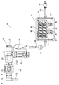
- FIG. 1 is a diagram illustrating an outline of the tightening device 10 of the present invention
- FIG. 2 is a schematic block diagram of the tightening device 10.
- the tightening device 10 is constituted by the tightener 20 and the control device 30, and the tightener 20 is provided with the torque detector 50 which detects torque acting on a socket.
- a double-shaft power wrench in which a drive shaft 21 consists of an inner shaft and an outer shaft 22 is exemplified as the tightener 20.
- the power wrench is not limited to a double-shaft power wrench and may be a single-shaft power wrench, and the tightener 20 may be an impact wrench, an impact driver, an impact/hammer drill, or the like.
- the inner shaft and the outer shaft 22 forming the drive shaft 21 can be rotated in opposite directions to each other by a motor 24 built into a housing 23.
- the inner shaft and the outer shaft 22 can be connected to the motor 24 by a deceleration mechanism 28 such as a planetary gear mechanism.
- the tightener 20 is provided, at a tip of the inner shaft, with a socket that is capable of mounting a fastening member such as a bolt or a nut. Also, a reaction receiver 25 that is equipped with an arm whose tip projects in a substantially perpendicular direction relative to the axial center of the drive shaft 21 is attached to a tip of the outer shaft 22.
- the tightener 20 on receiving an instruction from a control device 30 shown in FIG. 2 as a result of a trigger switch 26 shown in FIG. 1 being operated, drives the motor 24 and rotates the drive shaft 21. Also, as shown in FIG. 1 , the tightener 20 is equipped with a switch 27 for forward-reverse switching, and the rotation of the motor 24 can be reversed by operating the switch 27 for forward-reverse switching to enable tightening and loosening of a fastening member.
- the switch 27 for forward-reverse switching can be given as a switch that switches the rotation of the drive shaft 21 between forward and reverse mechanistically, through a gear change, clutch operation or the like of the deceleration mechanism 28. Also, the switch 27 for forward-reverse switching may be a switch that reverses the voltage that is supplied to the motor 24.
- the tightener 20 is equipped with the torque detector 50 for detecting the torque acting on the socket.
- the torque detector 50 transmits a signal relating to torque to the control device 30.
- a torque detector in which a torque sensor 51 that detects tightening torque is directly mounted between the drive shaft 21 and the socket can be employed as the torque detector 50.
- the torque acting on the socket may be torque detected from a change in the electrical system of the tightener 20, such as the change in motor current, for example. Also, the torque acting on the socket may also be obtained through conversion from the rotation angle of the drive shaft 21, the motor 24, the deceleration mechanism 28 or the like.
- the torque detector 50 rotates in tandem with the drive shaft 21 when mounted in the drive shaft 21 as shown in FIG. 1 , cable connection with the control device 30 is not possible. Accordingly, it is desirable that the signal relating to tightening torque measured by the torque sensor 51 is amplified by an amplifier circuit 52, input to the CPU 54 after undergoing A/D conversion in an A/D converter circuit 53, and wirelessly transmitted via a RF (Radio Frequency) circuit 55 and an antenna 56, as shown in FIG. 2 . Power supply to the torque detector 50 can be performed by installing a small battery in the torque detector 50.
- a distortion gauge adhered to the outer shaft 22 can be exemplified as the torque sensor 51.
- the tightening torque acting on the outer shaft 22 is output as a voltage change caused by the resistance change of the distortion gauge.
- the control device 30 is, as shown in FIG. 1 , electrically connected to the tightener 20 by a connection cable 60, and is capable of communicating with the tightener 20 and supplying power to the tightener 20.
- the control device 30 needs to perform setting and adjustment according to the performance and characteristics of the tightener 20. Accordingly, erroneous measurement or the like may occur when a different tightener 20 is connected to the control device 30.
- a configuration may be adopted in which the tightener 20 and the control device 30 are connected by a connector 64, with the length of the connector 64 being selectable according to the work environment.
- the control device 30 can, furthermore, be connected to a commercial power source by a power cable 62 that has a plug 61 connected to a tip thereof.
- the control device 30 incorporates a control means 32 shown in FIG. 2 in a box-type casing 31, as shown in FIG. 1 .
- the control means 32 is provided with a control unit 33 that is mainly constituted by electronic components including a CPU 34, a memory 35 such as RAM or ROM, and a D/A converter, and can be realized by various programs or the like stored in the memory 35.
- a functional block relating to typical functions that are realized by these connections is depicted. It should naturally be understood that these functional blocks can be realized using only hardware, only software, or a combination of hardware and software.
- a set torque display unit 40 that displays a set torque that is desired by a user, and a measured torque display unit 41 that displays the tightening torque measured by the torque detector 50 are provided on one surface of the casing 31, as shown in FIG. 1 . Also, torque setting buttons 47 and 48 for the user to increase or decrease the set torque, and a mode switching switch 44 for switching between the tightening modes of a first tightening process and a second tightening process are provided. Furthermore, a torque setting range display unit 46 that indicates the range over which the set torque of the tightening device 10 can be set is provided on the casing 31.
- a digital display employing LEDs can be used for the set torque display unit 40 and the measured torque display unit 41.
- One or both of these display units can, in the case where an anomaly of some kind occurs in the tightening device 10, be used as an error display unit for displaying the anomaly.
- reference numeral 42 denotes a set torque sub display unit that displays the set torque when the torque setting buttons 47 and 48 are operated, and is smaller than the set torque display unit 40.
- the torque setting buttons 47 and 48 are a minus button 47 for reducing the set torque and a plus button 48 for increasing the set torque. These torque setting buttons 47 and 48 can also be used as error cancellation buttons by operating one of the buttons when an anomaly of some kind occurs in the tightening device 10.
- the mode switching switch 44 is a switch for switching between two different tightening modes, and a press button switch, a dial switch, a slide switch or the like can be employed therefor.
- a display unit that displays the residing tightening mode is disposed in a suitable place in the mode switching switch 44 or on the casing 31, so as to enable the tightening mode to which the mode switching switch 44 is set to be visually checked.
- an LED 45 that is illuminated in correspondence with one of the tightening mode is disposed in the display unit. The integrated LED 45 is illuminated when the mode switching switch 44 that is illustrated is set to one of the tightening modes (the second tightening process in the present embodiment).
- the residing tightening mode can be visually checked as a result of the mode switching switch 44 itself being illuminated, which has the advantage of preventing erroneous operation and the like.
- the torque setting range display unit 46 indicates the minimum and maximum set torque of the tightening device 10, as shown in FIG. 1 .
- the setting range stamped into a plate as shown in FIG. 1 or printed on a sticker and attached to the casing 31 can be exemplified as the torque setting range display unit 46.
- a digital display can also be used therefor similarly to the above set torque display unit 40 and the like.
- the control unit 33 constituting the control means 32 has, as shown in FIG. 2 , the abovementioned display units 40, 41 and 42, buttons 47 and 78, and mode switching switch 44 connected thereto, together with a motor drive circuit 36 for driving the motor 24 of the tightener 20 via the trigger switch 26, and an RF circuit 37 and an antenna 38 for performing wireless communication with the torque detector 50.
- output adjustment of the motor 24 by the motor drive circuit 36 can be performed by phase control or PWM control.
- All programs for controlling the tightener 20 are stored in the memory 35.
- stored in the memory 35 are set torques set by the user in correspondence with the respective tightening modes of the first tightening process and the second tightening process, tightening programs and various parameters corresponding to the respective tightening modes, the residing tightening mode, the control amount of the motor drive circuit 36 for adjusting the output of the motor 24 based on the measured torque that is received and the set torque, and the like.
- Control of the tightening device 10 configured such as described above can be broadly divided, as shown in FIG. 3 , into a mode switching flow ( FIG. 4 , step S001), a set torque changing flow ( FIG. 5 , step S002), and a tightening flow ( FIG. 6 ) including the first tightening process (step S003) and the second tightening process (step S004).
- the mode switching flow is a flow for switching between the first tightening process and the second tightening process.
- the tightening mode switched to by the mode switching switch 44 can be discriminated by referring to the LED 45.
- the LED 45 is turned off in the first tightening process and turned on in the second tightening process. Note that, in order to prevent erroneous operation, it is desirable to deactivate operation of the mode switching switch 44 during the set torque changing flow, the first tightening process and the second tightening process which will be discussed later.
- the set torque changing flow (step S002) shown in FIG. 5 is performed after the mode switching flow (step S001) as shown in FIG. 3 .
- This set torque changing flow is executed following the mode switching flow at the time of the initial setting of the tightening device 10 or in the case of changing the set torque of the respective tightening modes.
- the set torque (first set torque) of the first tightening process and the set torque (second set torque) of the second tightening process are set.
- execution of the set torque changing flow can be skipped.
- the set torque changing flow is for setting and storing the set torque for the residing tightening mode, when the torque setting buttons 47 and 78 are operated.
- step S201 when the torque setting button 47 or 48 is operated (step S201), the control unit 33 increments or decrements the set torque that is stored in the memory 35 by the designated value, according to the operation of the torque setting button 47 or 48 (step S202), as shown in FIG. 5 . Processing for storing the new set torque in the memory 35 as the set torque is then performed (step S203).
- step S203 it is desirable to deactivate operation of the torque setting buttons 47 and 48 during the mode switching flow, the first tightening process and the second tightening process in order to prevent erroneous operation, and a configuration may also be adopted in which the processing moves to step S203 after waiting for the torque setting button 47 or 48 to subsequently be operated within a predetermined time period after the torque setting button 47 or 48 has been operated.
- step S003 After the set torque of each tightening mode has been set using the set torque changing flow (step S002), actual tightening process that depends on the selected tightening mode (step S003, step S004) follows, as shown in FIGS. 3 and 6 .
- the motor 24 is started at a predetermined initial output (V0) and maintains the initial output (V0).
- V0 initial output
- V0 initial output
- V0 initial output
- V0 initial output
- V0 initial output
- V0 initial output
- V0 initial output
- V0 initial output
- V0 initial output
- V0 initial output
- V0 initial output
- V0 initial output
- V0 initial output
- V0 initial output
- V0 initial output
- VF control start torque
- VB minimum output
- the first tightening process is a tightening mode in which the motor 24 has a large initial output.
- the initial output (V0) of the motor 24, as shown in FIG. 7 is larger than in the tightening mode of the second tightening process which will be shown next (see FIGS. 7 and 8 ). Accordingly, there if a risk of the tightening torque overshooting if the first tightening process is executed in order to check whether a tightened fastening member is tightened to a predetermined torque or greater. On the other hand, because the motor 24 has a large initial output, there is an advantage in that tightening can be performed in a short time.
- the second tightening process is a tightening mode for checking whether the fastening member tightened in the abovementioned first tightening process is tightened to a predetermined torque or greater.
- the second tightening process is a tightening mode in which the initial output (V0) of the motor 24, as shown in FIG. 8 , is less than the first tightening process.
- FIG. 6 A more detailed control flow of the tightening modes is shown in FIG. 6 . Note that although the first tightening process and the second tightening process are described together, when tightening a fastening member, first, the first tightening process of step S003 is executed, and then the second tightening process of step S004 is executed after tightening the fastening member to a predetermined set torque. Selection of these tightening modes is performed by operating the mode switching switch 44.
- the tightening flow is started by turning on the trigger switch 26 in a state where the socket of the tightener 20 is fitted to the fastening member (step S301).
- the trigger switch 26 is turned on by the user pulling the trigger switch 26 with a finger.
- the control unit 33 controls power supply from the motor drive circuit 36 to the motor 24 according to the residing tightening mode and the set torque thereof with reference to the memory 35, and drives the motor 24 at the initial output (V0) (step S302).
- the reaction receiver 25 thereby rotates in the reverse direction to the tightening direction of the socket and contacts another fastening member or the like, and the fastening member starts being tightened by the socket.
- the initial output (V0) is set to satisfy the following relationship, where VB is the minimum starting output of the motor 24: initial output of first tightening process > initial output of second tightening process ⁇ VB. More favorable checking tightening can be performed when the initial output of the second tightening process coincides with or most nearly approximates the minimum starting output (VB).
- the torque detector 50 detects the torque acting on the socket, and transmits the detected torque to the control means 32 as the measured torque.
- the motor is driven at the initial output (V0) until the measured torque reaches the prescribed control start torque (VF) corresponding to each tightening mode (No at step S303; range indicated by circled number 1 in FIGS. 7 and 8 ).
- VF prescribed control start torque
- step S304 motor feedback control is started (step S304; range indicated by circled number 2 in FIGS. 7 and 8 ).
- prescribed torque (VF) can be set in correspondence with the tightening mode.
- the control start torque (VF) can be set respectively in the first tightening process (first control start torque) and the second tightening process (second control start torque), in which case: first control start torque (VF) ⁇ second control start torque (VF). Desirably, the following relationship is satisfied: first control start torque (VF) > second control start torque (VF).
- step S304 in the case where the rate of increase of measured torque is greater than a predetermined value, based on the measured torque from the torque detector 50 (Yes in step S305), the control unit 33 performs control to reduce the power supply from the motor drive circuit 36 to the motor 24 (step S306), and if the rate of increase of measured torque is less than or equal to the predetermined value (No in step S305), the processing proceeds to the following step S307.
- step S307 the control unit 33 performs control to increase the power supply from the motor drive circuit 36 to the motor 24 (step S308), and if the rate of increase of measured torque is greater than or equal to the predetermined value (No in step S307), the processing proceeds to the following step S309.
- step S305 to S308 is executed until the measured torque from the torque detector 50 reaches the set torque T set in correspondence with each of the tightening modes (No in step S309).
- the control unit 33 blocks the power supply from the motor drive circuit 36 to the motor 24, and stop the output of the motor 24 (step S310; circled number 3 in FIGS. 7 and 8 ).
- a graph showing the change in tightening torque in the tightening flow corresponding to each tightening mode, and a graph showing the change in output of the motor 24 are respectively shown as A and B in FIGS. 7 and 8 .
- the measured torque increases approximately linearly in each of the tightening modes due to the initial output (V0) being applied, and then when the first control start torque or the second control start torque (VF) corresponding to the tightening mode is reached, the measured torque increases in a phased manner through repeated increases and decreases in torque, and approaches the set torque T.
- the motor 24 has a large initial output in the first tightening process compared with the second tightening process, tightening can be performed in a short time, although at the risk of the tightening torque overshooting.
- the fastening member would be tightened to an even greater tightening torque if the first tightening process were implemented in the second tightening process which is for checking the tightening torque.
- the tightening torque can be increased to the set torque.
- the second tightening process is implemented on a fastening member that was tightened to the set torque or greater in the first tightening process, it can be confirmed that the fastening member is tightened to the set torque or greater, without further increasing or loosening the tightening torque.
- first tightening process and the second tightening process can also be executed continuously on each fastening member, or the first tightening process may firstly be executed on a plurality of fastening members, and the second tightening process may then be executed collectively on these fastening members.
- a configuration may be adopted in which only the second tightening process is executed on a fastening member tightened by another tightening device.
Abstract
Description
- The present invention relates to a tightening device that is able to tighten a fastening member such as a bolt or a nut using a plurality of tightening processes.
- In order to increase the accuracy with which fastening members such as bolts or nuts are tightened, a known tightener measures the tightening torque that acts on the fastening member, and is numerically controlled to end the tightening when the measured torque reaches a set torque (e.g., see
JP 2013-166211A - Also, additional tightening that involves torque being further applied to tighten a fastening member that has already been tightened is performed in some cases (see
JP 2013-166211A - There is a need for a way of checking whether tightening has actually been performed to a desired set torque or greater, after a fastening member has been tightened or after additional tightening has been performed.
- In tightening the wheel nuts of a vehicle, the wheel nuts are firstly tightened and run in, and then loosened and tightened again in order to check whether tightening has been performed to a prescribed set torque. Further running in thus needs to be performed when wheel nuts that have already been tightened once are loosened and retightened, making it difficult to determine whether the tightening torque has really reached the set torque.
- An object of the present invention is to provide a tightening device that is able to check that a fastening member has been fastened to a desired set torque or greater after being tightened, without loosening the fastening member.
- In order to solve the above problems, a tightening device of the present invention is a tightening device including a motor, a motor drive circuit that drives the motor, a drive shaft that is rotated by the motor, has a socket mounted on a tip thereof, and is configured to tighten a fastening member, a torque detector that detects a tightening torque that acts on the socket, and a control unit that controls the motor drive circuit based on a set torque set in advance and a measured torque measured by the torque detector. The control unit includes a motor switching switch that switches between a first tightening process of controlling the motor drive circuit, adjusting an output of the motor after the measured torque that is measured by the torque detector has reached a preset first control start torque, such that the measured torque reaches a preset first set torque in a phased manner through repeated increases and decreases in torque, and blocking power supply to the motor when the measured torque reaches the first set torque, and a second tightening process of controlling the motor drive circuit to drive the motor at an initial output that is less than in the first tightening process, adjusting the output of the motor after the measured torque that is measured by the torque detector has reached a preset second control start torque, such that the measured torque reaches a preset second set torque in a phased manner through repeated increases and decreases in torque, and blocking power supply to the motor when the measured torque reaches the second set torque.
- The mode switching switch desirably has a display unit that enables the mode that has been switched to, out of the first tightening process and the second tightening process, to be visually checked.
- According to the tightening device of the present invention, the tightening mode can be changed to shift to a second tightening process by operating a mode switching switch, after a fastening member has been tightened in a first tightening process with a first setting torque as the target value. In the second tightening process, a motor is driven at an initial output that is less than the initial output in the first tightening process, and tightening is implemented with a second set torque as the target value. By performing this second tightening process, it can be confirmed that the fastening member is tightened to at least the second set torque.
- The second tightening process is able to prevent over-tightening, or so-called overshooting, with respect to the second set torque, since the initial output of the motor is less than in the first tightening process, and tightening is performed by increasing the torque in a phased manner through repeated increases and decreases in torque.
- Also, because it can be visually checked which tightening process is the residing tightening process when the mode switching switch is operated, erroneous operation can be prevented.
-
-
FIG. 1 is a schematic diagram illustrating a tightening device according to one embodiment of the present invention. -
FIG. 2 is a block diagram of a tightening device according to one embodiment of the present invention. -
FIG. 3 is a flowchart showing the overall flow of a tightening method according to one embodiment of the present invention. -
FIG. 4 is a flowchart showing a mode switching flow of a tightening device according to one embodiment of the present invention. -
FIG. 5 is a flowchart showing a set torque changing flow of a tightening device according to one embodiment of the present invention. -
FIG. 6 is a flowchart showing a tightening flow of a tightening device according to one embodiment of the present invention. -
FIG. 7A is a graph showing the change in tightening torque in a tightening mode of a first tightening process, andFIG. 7B is a graph showing the change in motor output. -
FIG. 8A is a graph showing the change in tightening torque in a tightening mode of a second tightening process, andFIG. 8B is a graph showing the change in motor output. - Hereinafter, an embodiment in which a tightening
device 10 of the present invention is applied to a numerically controlled tightening device constituted by atightener 20 serving as a main body that performs the tightening, acontrol device 30 that controls thetightener 20, and atorque detector 50 that measures torque, as shown inFIGS. 1 and2 , will be described. Note that a configuration can also be adopted in which some or all of the functions of thecontrol device 30 are incorporated in thetightener 20, or some of the functions of thecontrol device 30 may be executed by an external PC or the like. - Also, in the following embodiment, the tightening process consists of a first tightening process and a second tightening process as shown in
FIG. 3 , with the first tightening process being a normal tightening mode, and the second tightening process serving as a checking tightening mode that can check whether the tightening torque is a set torque or greater. -
FIG. 1 is a diagram illustrating an outline of thetightening device 10 of the present invention, andFIG. 2 is a schematic block diagram of thetightening device 10. As shown in the diagrams, thetightening device 10 is constituted by thetightener 20 and thecontrol device 30, and thetightener 20 is provided with thetorque detector 50 which detects torque acting on a socket. - In the embodiment shown in
FIG. 1 , a double-shaft power wrench in which adrive shaft 21 consists of an inner shaft and anouter shaft 22 is exemplified as thetightener 20. However, the power wrench is not limited to a double-shaft power wrench and may be a single-shaft power wrench, and thetightener 20 may be an impact wrench, an impact driver, an impact/hammer drill, or the like. - In the double-
shaft tightener 20, the inner shaft and theouter shaft 22 forming thedrive shaft 21 can be rotated in opposite directions to each other by amotor 24 built into ahousing 23. The inner shaft and theouter shaft 22 can be connected to themotor 24 by adeceleration mechanism 28 such as a planetary gear mechanism. - The
tightener 20 is provided, at a tip of the inner shaft, with a socket that is capable of mounting a fastening member such as a bolt or a nut. Also, areaction receiver 25 that is equipped with an arm whose tip projects in a substantially perpendicular direction relative to the axial center of thedrive shaft 21 is attached to a tip of theouter shaft 22. - The
tightener 20, on receiving an instruction from acontrol device 30 shown inFIG. 2 as a result of atrigger switch 26 shown inFIG. 1 being operated, drives themotor 24 and rotates thedrive shaft 21. Also, as shown inFIG. 1 , thetightener 20 is equipped with aswitch 27 for forward-reverse switching, and the rotation of themotor 24 can be reversed by operating theswitch 27 for forward-reverse switching to enable tightening and loosening of a fastening member. Theswitch 27 for forward-reverse switching can be given as a switch that switches the rotation of thedrive shaft 21 between forward and reverse mechanistically, through a gear change, clutch operation or the like of thedeceleration mechanism 28. Also, theswitch 27 for forward-reverse switching may be a switch that reverses the voltage that is supplied to themotor 24. - The
tightener 20 is equipped with thetorque detector 50 for detecting the torque acting on the socket. Thetorque detector 50 transmits a signal relating to torque to thecontrol device 30. As shown inFIG. 1 , a torque detector in which atorque sensor 51 that detects tightening torque is directly mounted between thedrive shaft 21 and the socket can be employed as thetorque detector 50. The torque acting on the socket may be torque detected from a change in the electrical system of thetightener 20, such as the change in motor current, for example. Also, the torque acting on the socket may also be obtained through conversion from the rotation angle of thedrive shaft 21, themotor 24, thedeceleration mechanism 28 or the like. - Because the
torque detector 50 rotates in tandem with thedrive shaft 21 when mounted in thedrive shaft 21 as shown inFIG. 1 , cable connection with thecontrol device 30 is not possible. Accordingly, it is desirable that the signal relating to tightening torque measured by thetorque sensor 51 is amplified by anamplifier circuit 52, input to theCPU 54 after undergoing A/D conversion in an A/D converter circuit 53, and wirelessly transmitted via a RF (Radio Frequency)circuit 55 and anantenna 56, as shown inFIG. 2 . Power supply to thetorque detector 50 can be performed by installing a small battery in thetorque detector 50. - As a specific embodiment, a distortion gauge adhered to the
outer shaft 22 can be exemplified as thetorque sensor 51. The tightening torque acting on theouter shaft 22 is output as a voltage change caused by the resistance change of the distortion gauge. - The
control device 30 is, as shown inFIG. 1 , electrically connected to thetightener 20 by aconnection cable 60, and is capable of communicating with thetightener 20 and supplying power to thetightener 20. Note that thecontrol device 30 needs to perform setting and adjustment according to the performance and characteristics of thetightener 20. Accordingly, erroneous measurement or the like may occur when adifferent tightener 20 is connected to thecontrol device 30. Thus, it is desirable for theconnection cable 60 to directly couple thetightener 20 to thecontrol device 30 in an undetachable manner. Note that a configuration may be adopted in which thetightener 20 and thecontrol device 30 are connected by aconnector 64, with the length of theconnector 64 being selectable according to the work environment. - The
control device 30 can, furthermore, be connected to a commercial power source by apower cable 62 that has aplug 61 connected to a tip thereof. - As a specific embodiment, the
control device 30 incorporates a control means 32 shown inFIG. 2 in a box-type casing 31, as shown inFIG. 1 . The control means 32 is provided with acontrol unit 33 that is mainly constituted by electronic components including aCPU 34, amemory 35 such as RAM or ROM, and a D/A converter, and can be realized by various programs or the like stored in thememory 35. InFIG. 2 , a functional block relating to typical functions that are realized by these connections is depicted. It should naturally be understood that these functional blocks can be realized using only hardware, only software, or a combination of hardware and software. - A set
torque display unit 40 that displays a set torque that is desired by a user, and a measuredtorque display unit 41 that displays the tightening torque measured by thetorque detector 50 are provided on one surface of thecasing 31, as shown inFIG. 1 . Also,torque setting buttons mode switching switch 44 for switching between the tightening modes of a first tightening process and a second tightening process are provided. Furthermore, a torque settingrange display unit 46 that indicates the range over which the set torque of the tighteningdevice 10 can be set is provided on thecasing 31. - A digital display employing LEDs, for example, can be used for the set
torque display unit 40 and the measuredtorque display unit 41. One or both of these display units can, in the case where an anomaly of some kind occurs in the tighteningdevice 10, be used as an error display unit for displaying the anomaly. Note that, inFIG. 1 ,reference numeral 42 denotes a set torque sub display unit that displays the set torque when thetorque setting buttons torque display unit 40. - The
torque setting buttons minus button 47 for reducing the set torque and aplus button 48 for increasing the set torque. Thesetorque setting buttons device 10. - The
mode switching switch 44 is a switch for switching between two different tightening modes, and a press button switch, a dial switch, a slide switch or the like can be employed therefor. A display unit that displays the residing tightening mode is disposed in a suitable place in themode switching switch 44 or on thecasing 31, so as to enable the tightening mode to which themode switching switch 44 is set to be visually checked. In the illustrated example, anLED 45 that is illuminated in correspondence with one of the tightening mode is disposed in the display unit. Theintegrated LED 45 is illuminated when themode switching switch 44 that is illustrated is set to one of the tightening modes (the second tightening process in the present embodiment). It is conceivable, for example, to display the residing tightening mode on the abovementioned measuredtorque display unit 41 or the like, and to switch this display when tightening is started, although, in this case, the tightening mode cannot be checked while tightening is being performed. Also, the user is required to perform other operations in order to check the tightening mode. On the other hand, in the present invention, the residing tightening mode can be visually checked as a result of themode switching switch 44 itself being illuminated, which has the advantage of preventing erroneous operation and the like. - The torque setting
range display unit 46 indicates the minimum and maximum set torque of the tighteningdevice 10, as shown inFIG. 1 . The setting range stamped into a plate as shown inFIG. 1 or printed on a sticker and attached to thecasing 31 can be exemplified as the torque settingrange display unit 46. A digital display can also be used therefor similarly to the above settorque display unit 40 and the like. - The
control unit 33 constituting the control means 32 has, as shown inFIG. 2 , theabovementioned display units buttons 47 and 78, andmode switching switch 44 connected thereto, together with amotor drive circuit 36 for driving themotor 24 of thetightener 20 via thetrigger switch 26, and anRF circuit 37 and anantenna 38 for performing wireless communication with thetorque detector 50. For example, output adjustment of themotor 24 by themotor drive circuit 36 can be performed by phase control or PWM control. - All programs for controlling the
tightener 20 are stored in thememory 35. For example, stored in thememory 35 are set torques set by the user in correspondence with the respective tightening modes of the first tightening process and the second tightening process, tightening programs and various parameters corresponding to the respective tightening modes, the residing tightening mode, the control amount of themotor drive circuit 36 for adjusting the output of themotor 24 based on the measured torque that is received and the set torque, and the like. - Control of the tightening
device 10 configured such as described above can be broadly divided, as shown inFIG. 3 , into a mode switching flow (FIG. 4 , step S001), a set torque changing flow (FIG. 5 , step S002), and a tightening flow (FIG. 6 ) including the first tightening process (step S003) and the second tightening process (step S004). - The mode switching flow is a flow for switching between the first tightening process and the second tightening process.
- More specifically, as shown in
FIG. 4 , this involves processing for switching, when themode switching switch 44 is operated (step S101), the residing tightening mode between the first tightening process and the second tightening process (step S102), and storing the residing tightening mode in thememory 35 of the control unit 33 (step S103). The tightening mode switched to by themode switching switch 44 can be discriminated by referring to theLED 45. In the present embodiment, theLED 45 is turned off in the first tightening process and turned on in the second tightening process. Note that, in order to prevent erroneous operation, it is desirable to deactivate operation of themode switching switch 44 during the set torque changing flow, the first tightening process and the second tightening process which will be discussed later. - The set torque changing flow (step S002) shown in
FIG. 5 is performed after the mode switching flow (step S001) as shown inFIG. 3 . This set torque changing flow is executed following the mode switching flow at the time of the initial setting of the tighteningdevice 10 or in the case of changing the set torque of the respective tightening modes. In the present embodiment, the set torque (first set torque) of the first tightening process and the set torque (second set torque) of the second tightening process are set. In the case of using thetightening device 10 in a state where the set torque has already been set or changed, execution of the set torque changing flow can be skipped. - The set torque changing flow is for setting and storing the set torque for the residing tightening mode, when the
torque setting buttons 47 and 78 are operated. - As a specific embodiment, when the
torque setting button control unit 33 increments or decrements the set torque that is stored in thememory 35 by the designated value, according to the operation of thetorque setting button 47 or 48 (step S202), as shown inFIG. 5 . Processing for storing the new set torque in thememory 35 as the set torque is then performed (step S203). - Note that it is desirable to deactivate operation of the
torque setting buttons torque setting button torque setting button - After the set torque of each tightening mode has been set using the set torque changing flow (step S002), actual tightening process that depends on the selected tightening mode (step S003, step S004) follows, as shown in
FIGS. 3 and6 . - Here, an outline of the tightening modes of the first tightening process and the second tightening process according to one embodiment of the present invention will be described.
- Although the values differ, in each tightening mode, as shown in
FIGS. 7 and 8 , themotor 24 is started at a predetermined initial output (V0) and maintains the initial output (V0). After the measured torque that is detected by thetorque detector 50 has reached a predetermined control start torque (VF) (the first control start torque in the first tightening process, and the second control start torque in the second tightening process), the output of themotor 24 is feedback controlled based on the measured torque. In feedback control, themotor 24 is driven while adjusting the output within a predetermined range defined by a maximum output (VR) and a minimum output (VB) of themotor 24. The measured torque thereby increases in a phased manner through repeated increases and decreases in torque. - Power supply to the motor is then blocked when the measured torque reaches the set torque set in advance.
- The first tightening process is a tightening mode in which the
motor 24 has a large initial output. - In this tightening mode, the initial output (V0) of the
motor 24, as shown inFIG. 7 , is larger than in the tightening mode of the second tightening process which will be shown next (seeFIGS. 7 and 8 ). Accordingly, there if a risk of the tightening torque overshooting if the first tightening process is executed in order to check whether a tightened fastening member is tightened to a predetermined torque or greater. On the other hand, because themotor 24 has a large initial output, there is an advantage in that tightening can be performed in a short time. - The second tightening process is a tightening mode for checking whether the fastening member tightened in the abovementioned first tightening process is tightened to a predetermined torque or greater.
- The second tightening process is a tightening mode in which the initial output (V0) of the
motor 24, as shown inFIG. 8 , is less than the first tightening process. - Thus, although the second tightening process takes longer to reach a predetermined set torque due to the low initial output (V0) of the
motor 24 that is set, there is an advantage in that over-tightening (overshooting) can be prevented. - A more detailed control flow of the tightening modes is shown in
FIG. 6 . Note that although the first tightening process and the second tightening process are described together, when tightening a fastening member, first, the first tightening process of step S003 is executed, and then the second tightening process of step S004 is executed after tightening the fastening member to a predetermined set torque. Selection of these tightening modes is performed by operating themode switching switch 44. - The tightening flow is started by turning on the
trigger switch 26 in a state where the socket of thetightener 20 is fitted to the fastening member (step S301). With thetightener 20 shown inFIG. 1 , thetrigger switch 26 is turned on by the user pulling thetrigger switch 26 with a finger. - When the
trigger switch 26 is turned on (step S301), thecontrol unit 33 controls power supply from themotor drive circuit 36 to themotor 24 according to the residing tightening mode and the set torque thereof with reference to thememory 35, and drives themotor 24 at the initial output (V0) (step S302). Thereaction receiver 25 thereby rotates in the reverse direction to the tightening direction of the socket and contacts another fastening member or the like, and the fastening member starts being tightened by the socket. - The initial output (V0) is set to satisfy the following relationship, where VB is the minimum starting output of the motor 24: initial output of first tightening process > initial output of second tightening process ≥ VB. More favorable checking tightening can be performed when the initial output of the second tightening process coincides with or most nearly approximates the minimum starting output (VB).
- When the
motor 24 starts driving, thetorque detector 50 detects the torque acting on the socket, and transmits the detected torque to the control means 32 as the measured torque. The motor is driven at the initial output (V0) until the measured torque reaches the prescribed control start torque (VF) corresponding to each tightening mode (No at step S303; range indicated by circled number 1 inFIGS. 7 and 8 ). When the measured torque reaches the prescribed control start torque (VF) (YES at step S303; P inFIGS. 7 and 8 ), motor feedback control is started (step S304; range indicated by circlednumber 2 inFIGS. 7 and 8 ). Note that prescribed torque (VF) can be set in correspondence with the tightening mode. The control start torque (VF) can be set respectively in the first tightening process (first control start torque) and the second tightening process (second control start torque), in which case: first control start torque (VF) ≥ second control start torque (VF). Desirably, the following relationship is satisfied: first control start torque (VF) > second control start torque (VF). For example, inFIGS. 7 and 8 , the first control start torque is 0.7 times the set torque T (VF = T×0.7), and the second control start torque is VF = 50 N·m (< T×0.5). - In the motor feedback control (step S304), as shown in
FIGS. 7 and 8 , in the case where the rate of increase of measured torque is greater than a predetermined value, based on the measured torque from the torque detector 50 (Yes in step S305), thecontrol unit 33 performs control to reduce the power supply from themotor drive circuit 36 to the motor 24 (step S306), and if the rate of increase of measured torque is less than or equal to the predetermined value (No in step S305), the processing proceeds to the following step S307. - As shown in
FIGS. 7 and 8 , conversely, in the case where the rate of increase of measured torque from thetorque detector 50 is less than a predetermined value (Yes in step S307), thecontrol unit 33 performs control to increase the power supply from themotor drive circuit 36 to the motor 24 (step S308), and if the rate of increase of measured torque is greater than or equal to the predetermined value (No in step S307), the processing proceeds to the following step S309. - The feedback control (steps S305 to S308) is executed until the measured torque from the
torque detector 50 reaches the set torque T set in correspondence with each of the tightening modes (No in step S309). When measured torque reaches the set torque T (Yes in step S309), thecontrol unit 33 blocks the power supply from themotor drive circuit 36 to themotor 24, and stop the output of the motor 24 (step S310; circled number 3 inFIGS. 7 and 8 ). - A graph showing the change in tightening torque in the tightening flow corresponding to each tightening mode, and a graph showing the change in output of the
motor 24 are respectively shown as A and B inFIGS. 7 and 8 . - Referring to
FIGS. 7 and 8 , it can be seen that the measured torque increases approximately linearly in each of the tightening modes due to the initial output (V0) being applied, and then when the first control start torque or the second control start torque (VF) corresponding to the tightening mode is reached, the measured torque increases in a phased manner through repeated increases and decreases in torque, and approaches the set torque T. - Because the
motor 24 has a large initial output in the first tightening process compared with the second tightening process, tightening can be performed in a short time, although at the risk of the tightening torque overshooting. In this case, the fastening member would be tightened to an even greater tightening torque if the first tightening process were implemented in the second tightening process which is for checking the tightening torque. - In the present invention, overshooting is unlikely to occur, because the tightening torque is checked in the checking tightening mode of the second tightening process in which the initial output (V0) of the
motor 24 is less than in the first tightening process. Accordingly, it can be accurately confirmed that the fastening member is tightened to the set tightening torque or greater. - That is, when the second tightening process is implemented on a fastening member that was tightened to less than the set torque in the first tightening process, the tightening torque can be increased to the set torque. On the other hand, when the second tightening process is implemented on a fastening member that was tightened to the set torque or greater in the first tightening process, it can be confirmed that the fastening member is tightened to the set torque or greater, without further increasing or loosening the tightening torque.
- Being able to check that tightening has been performed to the set torque or greater in the second tightening process, without loosening the fastening member, is highly effective when applied to the tightening of wheel nuts, which was conventionally performed by loosening and retightening the wheel nuts.
- The foregoing description is intended to illustrate the present invention, and should not be construed as limiting the invention defined in the claims or as restricting the scope of the invention. Also, the configuration of each element of the invention is not limited to the foregoing examples, and various modifications can be made within the technical scope of the claims.
- For example, the first tightening process and the second tightening process can also be executed continuously on each fastening member, or the first tightening process may firstly be executed on a plurality of fastening members, and the second tightening process may then be executed collectively on these fastening members. Also, a configuration may be adopted in which only the second tightening process is executed on a fastening member tightened by another tightening device.
Claims (3)
- A tightening device comprising:a motor;a motor drive circuit that drives the motor;a drive shaft that is rotated by the motor, has a socket mounted on a tip thereof, and is configured to tighten a fastening member;a torque detector that detects a tightening torque that acts on the socket; anda control unit that controls the motor drive circuit based on a set torque set in advance and a measured torque measured by the torque detector,wherein the control unit includes a motor switching switch that switches between a first tightening process of controlling the motor drive circuit, adjusting an output of the motor after the measured torque that is measured by the torque detector has reached a preset first control start torque, such that the measured torque reaches a preset first set torque in a phased manner through repeated increases and decreases in torque, and blocking power supply to the motor when the measured torque reaches the first set torque, and a second tightening process of controlling the motor drive circuit to drive the motor at an initial output that is less than in the first tightening process, adjusting the output of the motor after the measured torque that is measured by the torque detector has reached a preset second control start torque, such that the measured torque reaches a preset second set torque in a phased manner through repeated increases and decreases in torque, and blocking power supply to the motor when the measured torque reaches the second set torque.
- The tightening device according to claim 1,
wherein the mode switching switch has a display unit that enables the mode that has been switched to, out of the first tightening process and the second tightening process, to be visually checked. - The tightening device according to claim 2,
wherein the display unit of the mode switching switch is illuminated in a state where one of the modes has been switched to.
Applications Claiming Priority (1)
| Application Number | Priority Date | Filing Date | Title |
|---|---|---|---|
| JP2013227520A JP6245943B2 (en) | 2013-10-31 | 2013-10-31 | Fastening device |
Publications (2)
| Publication Number | Publication Date |
|---|---|
| EP2868436A1 true EP2868436A1 (en) | 2015-05-06 |
| EP2868436B1 EP2868436B1 (en) | 2019-01-02 |
Family
ID=51862118
Family Applications (1)
| Application Number | Title | Priority Date | Filing Date |
|---|---|---|---|
| EP14190722.0A Active EP2868436B1 (en) | 2013-10-31 | 2014-10-28 | Tightening device |
Country Status (5)
| Country | Link |
|---|---|
| US (1) | US9645026B2 (en) |
| EP (1) | EP2868436B1 (en) |
| JP (1) | JP6245943B2 (en) |
| KR (1) | KR102302490B1 (en) |
| CN (1) | CN104589260B (en) |
Cited By (1)
| Publication number | Priority date | Publication date | Assignee | Title |
|---|---|---|---|---|
| SE2130352A1 (en) * | 2021-12-10 | 2023-06-11 | Atlas Copco Ind Technique Ab | Method of controlling an electric motor of a tightening tool |
Families Citing this family (13)
| Publication number | Priority date | Publication date | Assignee | Title |
|---|---|---|---|---|
| JP6322387B2 (en) * | 2013-11-05 | 2018-05-09 | Tone株式会社 | Fastening device and fastening method |
| KR101633304B1 (en) * | 2015-07-02 | 2016-06-27 | 계양전기 주식회사 | Control method of electrically-drive tool |
| KR102302489B1 (en) * | 2015-08-31 | 2021-09-16 | 한국전력공사 | Apparatus for inducing aixal force of high strength bolt and method of inducing axial force using the same |
| US9696224B1 (en) * | 2015-12-31 | 2017-07-04 | Chung-Yu Tsai | Torque detection device |
| CN105856964A (en) * | 2016-06-19 | 2016-08-17 | 刘瑞 | Electric wrench for automobile tire |
| US10483901B2 (en) | 2017-07-10 | 2019-11-19 | Newfrey Llc | System and method for installation and verification of fasteners |
| CN107553114B (en) * | 2017-09-05 | 2024-02-20 | 沈阳工业大学 | Online detection and fastening device for bolts of wind generating set |
| CN108274227B (en) * | 2018-03-05 | 2023-09-26 | 王聪 | Automatic tightening device for bolt connecting member and working method thereof |
| CN109570989B (en) * | 2019-01-09 | 2024-01-12 | 成都凯天电子股份有限公司 | Method for determining consistency of assembly positions of bolts in switch assembly |
| CN110216616A (en) * | 2019-06-20 | 2019-09-10 | 国网河南省电力公司电力科学研究院 | A kind of Electric torque wrench and its man-machine interaction method |
| JP7153879B2 (en) * | 2019-06-24 | 2022-10-17 | パナソニックIpマネジメント株式会社 | Electric tool |
| CN113561113B (en) * | 2020-04-28 | 2022-09-20 | 南京泉峰科技有限公司 | Intelligent electric tool and control method thereof |
| CN111805231A (en) * | 2020-07-21 | 2020-10-23 | 格力电器(武汉)有限公司 | Electric screwdriver control circuit, electric screwdriver and automatic installation equipment for threaded fastener |
Citations (3)
| Publication number | Priority date | Publication date | Assignee | Title |
|---|---|---|---|---|
| DE3230642A1 (en) * | 1982-08-18 | 1984-02-23 | Volkswagenwerk Ag, 3180 Wolfsburg | Method and device for tightening a threaded connecting element |
| WO2011122361A1 (en) * | 2010-03-31 | 2011-10-06 | Hitachi Koki Co., Ltd. | Power tool |
| JP2013166211A (en) | 2012-02-15 | 2013-08-29 | Honda Motor Co Ltd | Tightening method and control device for tightening machine |
Family Cites Families (13)
| Publication number | Priority date | Publication date | Assignee | Title |
|---|---|---|---|---|
| JPS5524853A (en) * | 1978-08-07 | 1980-02-22 | Sanyo Kiko Kk | Controller of nut runner |
| JP2959946B2 (en) * | 1994-03-11 | 1999-10-06 | 日東精工株式会社 | Automatic part fastening machine and fastening method |
| JP2000094355A (en) * | 1998-09-22 | 2000-04-04 | Toyota Motor Corp | Torque wrench for clamping part in plastic region |
| DE10303235B4 (en) * | 2002-01-29 | 2011-03-31 | Makita Corp., Anjo | Torque-transmitting mechanisms and power tools with such torque-transmitting mechanisms |
| JP4400303B2 (en) * | 2004-05-12 | 2010-01-20 | パナソニック電工株式会社 | Impact rotary tool |
| JP4203459B2 (en) * | 2004-08-30 | 2009-01-07 | 日東工器株式会社 | Electric driver device |
| JP4339275B2 (en) * | 2005-05-12 | 2009-10-07 | 株式会社エスティック | Method and apparatus for controlling impact type screw fastening device |
| DE102006016448A1 (en) * | 2006-04-07 | 2007-10-11 | Robert Bosch Gmbh | Electric machine tool and method of operating the same |
| JP2008126320A (en) * | 2006-11-16 | 2008-06-05 | Toshiba Corp | Nut tightening method and manufacturing device of assembly |
| JP5182562B2 (en) * | 2008-02-29 | 2013-04-17 | 日立工機株式会社 | Electric tool |
| JP2013146846A (en) * | 2012-01-23 | 2013-08-01 | Max Co Ltd | Rotary tool |
| JP5775480B2 (en) * | 2012-03-27 | 2015-09-09 | トヨタ自動車株式会社 | Screw fastening method and screw fastening device |
| JP6322387B2 (en) * | 2013-11-05 | 2018-05-09 | Tone株式会社 | Fastening device and fastening method |
-
2013
- 2013-10-31 JP JP2013227520A patent/JP6245943B2/en active Active
-
2014
- 2014-10-24 US US14/522,877 patent/US9645026B2/en active Active
- 2014-10-28 EP EP14190722.0A patent/EP2868436B1/en active Active
- 2014-10-28 KR KR1020140147533A patent/KR102302490B1/en active IP Right Grant
- 2014-10-29 CN CN201410592952.7A patent/CN104589260B/en active Active
Patent Citations (3)
| Publication number | Priority date | Publication date | Assignee | Title |
|---|---|---|---|---|
| DE3230642A1 (en) * | 1982-08-18 | 1984-02-23 | Volkswagenwerk Ag, 3180 Wolfsburg | Method and device for tightening a threaded connecting element |
| WO2011122361A1 (en) * | 2010-03-31 | 2011-10-06 | Hitachi Koki Co., Ltd. | Power tool |
| JP2013166211A (en) | 2012-02-15 | 2013-08-29 | Honda Motor Co Ltd | Tightening method and control device for tightening machine |
Cited By (2)
| Publication number | Priority date | Publication date | Assignee | Title |
|---|---|---|---|---|
| SE2130352A1 (en) * | 2021-12-10 | 2023-06-11 | Atlas Copco Ind Technique Ab | Method of controlling an electric motor of a tightening tool |
| SE545773C2 (en) * | 2021-12-10 | 2024-01-09 | Atlas Copco Ind Technique Ab | Method of controlling an electric motor of a tightening tool |
Also Published As
| Publication number | Publication date |
|---|---|
| EP2868436B1 (en) | 2019-01-02 |
| CN104589260B (en) | 2018-05-11 |
| CN104589260A (en) | 2015-05-06 |
| JP2015085471A (en) | 2015-05-07 |
| JP6245943B2 (en) | 2017-12-13 |
| US20150114138A1 (en) | 2015-04-30 |
| US9645026B2 (en) | 2017-05-09 |
| KR20150050433A (en) | 2015-05-08 |
| KR102302490B1 (en) | 2021-09-15 |
Similar Documents
| Publication | Publication Date | Title |
|---|---|---|
| EP2868436B1 (en) | Tightening device | |
| EP2873487B1 (en) | Tightening device and tightening method | |
| US9233457B2 (en) | Control device for a hand-held power tool | |
| US8264374B2 (en) | Wireless data transmitting and receiving system | |
| US9878427B2 (en) | Hand-held power tool, in particular battery-powered screwdriver | |
| EP2604988B1 (en) | Power tool with force sensing electronic clutch | |
| CN112955283B (en) | Electric tool | |
| JP2013028251A (en) | Tire pneumatic monitoring device and trigger device | |
| US10661418B2 (en) | Threaded member tightening tool and drive time setting method for threaded member tightening tool | |
| JP2015085470A (en) | Fastening/loosening device and method for controlling the same | |
| JP6283500B2 (en) | Fastening device | |
| WO2022082065A1 (en) | Fastener including embedded sensor | |
| JP2016147317A (en) | Thread fastening state detection device of electric rotary tool, torque adjustment method of the same, and thread fastening control method by using the same | |
| JP6245944B2 (en) | Reaction force receiver and tightening device equipped with the same | |
| JP2015085474A (en) | Fastening device | |
| KR102064432B1 (en) | Controlling method for apparatus transmitting and receiving wireless power for vehicle | |
| KR102064430B1 (en) | Controlling method for apparatus transmitting and receiving wireless power for vehicle | |
| KR102064431B1 (en) | Apparatus for transmitting and receiving wireless power for vehicle | |
| KR102064428B1 (en) | Apparatus for transmitting and receiving wireless power for vehicle | |
| EP2724822A1 (en) | Power tool | |
| JP6943276B2 (en) | tool | |
| EP2835222B1 (en) | Torque multiplier |
Legal Events
| Date | Code | Title | Description |
|---|---|---|---|
| PUAI | Public reference made under article 153(3) epc to a published international application that has entered the european phase |
Free format text: ORIGINAL CODE: 0009012 |
|
| 17P | Request for examination filed |
Effective date: 20141028 |
|
| AK | Designated contracting states |
Kind code of ref document: A1 Designated state(s): AL AT BE BG CH CY CZ DE DK EE ES FI FR GB GR HR HU IE IS IT LI LT LU LV MC MK MT NL NO PL PT RO RS SE SI SK SM TR |
|
| AX | Request for extension of the european patent |
Extension state: BA ME |
|
| R17P | Request for examination filed (corrected) |
Effective date: 20151105 |
|
| RBV | Designated contracting states (corrected) |
Designated state(s): AL AT BE BG CH CY CZ DE DK EE ES FI FR GB GR HR HU IE IS IT LI LT LU LV MC MK MT NL NO PL PT RO RS SE SI SK SM TR |
|
| RAP1 | Party data changed (applicant data changed or rights of an application transferred) |
Owner name: SUBARU CORPORATION Owner name: TONE CO., LTD. |
|
| GRAP | Despatch of communication of intention to grant a patent |
Free format text: ORIGINAL CODE: EPIDOSNIGR1 |
|
| STAA | Information on the status of an ep patent application or granted ep patent |
Free format text: STATUS: GRANT OF PATENT IS INTENDED |
|
| RIC1 | Information provided on ipc code assigned before grant |
Ipc: B25B 23/147 20060101AFI20180801BHEP Ipc: B60B 29/00 20060101ALI20180801BHEP Ipc: G01L 5/24 20060101ALI20180801BHEP |
|
| INTG | Intention to grant announced |
Effective date: 20180821 |
|
| GRAS | Grant fee paid |
Free format text: ORIGINAL CODE: EPIDOSNIGR3 |
|
| GRAA | (expected) grant |
Free format text: ORIGINAL CODE: 0009210 |
|
| STAA | Information on the status of an ep patent application or granted ep patent |
Free format text: STATUS: THE PATENT HAS BEEN GRANTED |
|
| AK | Designated contracting states |
Kind code of ref document: B1 Designated state(s): AL AT BE BG CH CY CZ DE DK EE ES FI FR GB GR HR HU IE IS IT LI LT LU LV MC MK MT NL NO PL PT RO RS SE SI SK SM TR |
|
| REG | Reference to a national code |
Ref country code: GB Ref legal event code: FG4D |
|
| RIN1 | Information on inventor provided before grant (corrected) |
Inventor name: NAKAHATA, TATSUO Inventor name: SAITO, MANABU Inventor name: KUSHIDA, TOSHIHIKO Inventor name: HIRAI, TATSUO Inventor name: WATANABE, MASAO Inventor name: TORIGAI, YUKIO Inventor name: FUJIMOTO, KATSUHIRO |
|
| REG | Reference to a national code |
Ref country code: CH Ref legal event code: EP Ref country code: AT Ref legal event code: REF Ref document number: 1083759 Country of ref document: AT Kind code of ref document: T Effective date: 20190115 |
|
| REG | Reference to a national code |
Ref country code: IE Ref legal event code: FG4D |
|
| REG | Reference to a national code |
Ref country code: DE Ref legal event code: R096 Ref document number: 602014039013 Country of ref document: DE |
|
| REG | Reference to a national code |
Ref country code: NL Ref legal event code: MP Effective date: 20190102 |
|
| REG | Reference to a national code |
Ref country code: LT Ref legal event code: MG4D |
|
| REG | Reference to a national code |
Ref country code: AT Ref legal event code: MK05 Ref document number: 1083759 Country of ref document: AT Kind code of ref document: T Effective date: 20190102 |
|
| PG25 | Lapsed in a contracting state [announced via postgrant information from national office to epo] |
Ref country code: NL Free format text: LAPSE BECAUSE OF FAILURE TO SUBMIT A TRANSLATION OF THE DESCRIPTION OR TO PAY THE FEE WITHIN THE PRESCRIBED TIME-LIMIT Effective date: 20190102 |
|
| PG25 | Lapsed in a contracting state [announced via postgrant information from national office to epo] |
Ref country code: NO Free format text: LAPSE BECAUSE OF FAILURE TO SUBMIT A TRANSLATION OF THE DESCRIPTION OR TO PAY THE FEE WITHIN THE PRESCRIBED TIME-LIMIT Effective date: 20190402 Ref country code: FI Free format text: LAPSE BECAUSE OF FAILURE TO SUBMIT A TRANSLATION OF THE DESCRIPTION OR TO PAY THE FEE WITHIN THE PRESCRIBED TIME-LIMIT Effective date: 20190102 Ref country code: PL Free format text: LAPSE BECAUSE OF FAILURE TO SUBMIT A TRANSLATION OF THE DESCRIPTION OR TO PAY THE FEE WITHIN THE PRESCRIBED TIME-LIMIT Effective date: 20190102 Ref country code: LT Free format text: LAPSE BECAUSE OF FAILURE TO SUBMIT A TRANSLATION OF THE DESCRIPTION OR TO PAY THE FEE WITHIN THE PRESCRIBED TIME-LIMIT Effective date: 20190102 Ref country code: ES Free format text: LAPSE BECAUSE OF FAILURE TO SUBMIT A TRANSLATION OF THE DESCRIPTION OR TO PAY THE FEE WITHIN THE PRESCRIBED TIME-LIMIT Effective date: 20190102 Ref country code: SE Free format text: LAPSE BECAUSE OF FAILURE TO SUBMIT A TRANSLATION OF THE DESCRIPTION OR TO PAY THE FEE WITHIN THE PRESCRIBED TIME-LIMIT Effective date: 20190102 Ref country code: PT Free format text: LAPSE BECAUSE OF FAILURE TO SUBMIT A TRANSLATION OF THE DESCRIPTION OR TO PAY THE FEE WITHIN THE PRESCRIBED TIME-LIMIT Effective date: 20190502 |
|
| PG25 | Lapsed in a contracting state [announced via postgrant information from national office to epo] |
Ref country code: LV Free format text: LAPSE BECAUSE OF FAILURE TO SUBMIT A TRANSLATION OF THE DESCRIPTION OR TO PAY THE FEE WITHIN THE PRESCRIBED TIME-LIMIT Effective date: 20190102 Ref country code: RS Free format text: LAPSE BECAUSE OF FAILURE TO SUBMIT A TRANSLATION OF THE DESCRIPTION OR TO PAY THE FEE WITHIN THE PRESCRIBED TIME-LIMIT Effective date: 20190102 Ref country code: BG Free format text: LAPSE BECAUSE OF FAILURE TO SUBMIT A TRANSLATION OF THE DESCRIPTION OR TO PAY THE FEE WITHIN THE PRESCRIBED TIME-LIMIT Effective date: 20190402 Ref country code: IS Free format text: LAPSE BECAUSE OF FAILURE TO SUBMIT A TRANSLATION OF THE DESCRIPTION OR TO PAY THE FEE WITHIN THE PRESCRIBED TIME-LIMIT Effective date: 20190502 Ref country code: GR Free format text: LAPSE BECAUSE OF FAILURE TO SUBMIT A TRANSLATION OF THE DESCRIPTION OR TO PAY THE FEE WITHIN THE PRESCRIBED TIME-LIMIT Effective date: 20190403 Ref country code: HR Free format text: LAPSE BECAUSE OF FAILURE TO SUBMIT A TRANSLATION OF THE DESCRIPTION OR TO PAY THE FEE WITHIN THE PRESCRIBED TIME-LIMIT Effective date: 20190102 |
|
| REG | Reference to a national code |
Ref country code: DE Ref legal event code: R097 Ref document number: 602014039013 Country of ref document: DE |
|
| PG25 | Lapsed in a contracting state [announced via postgrant information from national office to epo] |
Ref country code: DK Free format text: LAPSE BECAUSE OF FAILURE TO SUBMIT A TRANSLATION OF THE DESCRIPTION OR TO PAY THE FEE WITHIN THE PRESCRIBED TIME-LIMIT Effective date: 20190102 Ref country code: AT Free format text: LAPSE BECAUSE OF FAILURE TO SUBMIT A TRANSLATION OF THE DESCRIPTION OR TO PAY THE FEE WITHIN THE PRESCRIBED TIME-LIMIT Effective date: 20190102 Ref country code: EE Free format text: LAPSE BECAUSE OF FAILURE TO SUBMIT A TRANSLATION OF THE DESCRIPTION OR TO PAY THE FEE WITHIN THE PRESCRIBED TIME-LIMIT Effective date: 20190102 Ref country code: SK Free format text: LAPSE BECAUSE OF FAILURE TO SUBMIT A TRANSLATION OF THE DESCRIPTION OR TO PAY THE FEE WITHIN THE PRESCRIBED TIME-LIMIT Effective date: 20190102 Ref country code: AL Free format text: LAPSE BECAUSE OF FAILURE TO SUBMIT A TRANSLATION OF THE DESCRIPTION OR TO PAY THE FEE WITHIN THE PRESCRIBED TIME-LIMIT Effective date: 20190102 Ref country code: CZ Free format text: LAPSE BECAUSE OF FAILURE TO SUBMIT A TRANSLATION OF THE DESCRIPTION OR TO PAY THE FEE WITHIN THE PRESCRIBED TIME-LIMIT Effective date: 20190102 Ref country code: IT Free format text: LAPSE BECAUSE OF FAILURE TO SUBMIT A TRANSLATION OF THE DESCRIPTION OR TO PAY THE FEE WITHIN THE PRESCRIBED TIME-LIMIT Effective date: 20190102 Ref country code: RO Free format text: LAPSE BECAUSE OF FAILURE TO SUBMIT A TRANSLATION OF THE DESCRIPTION OR TO PAY THE FEE WITHIN THE PRESCRIBED TIME-LIMIT Effective date: 20190102 |
|
| PLBE | No opposition filed within time limit |
Free format text: ORIGINAL CODE: 0009261 |
|
| STAA | Information on the status of an ep patent application or granted ep patent |
Free format text: STATUS: NO OPPOSITION FILED WITHIN TIME LIMIT |
|
| PG25 | Lapsed in a contracting state [announced via postgrant information from national office to epo] |
Ref country code: SM Free format text: LAPSE BECAUSE OF FAILURE TO SUBMIT A TRANSLATION OF THE DESCRIPTION OR TO PAY THE FEE WITHIN THE PRESCRIBED TIME-LIMIT Effective date: 20190102 |
|
| 26N | No opposition filed |
Effective date: 20191003 |
|
| PG25 | Lapsed in a contracting state [announced via postgrant information from national office to epo] |
Ref country code: SI Free format text: LAPSE BECAUSE OF FAILURE TO SUBMIT A TRANSLATION OF THE DESCRIPTION OR TO PAY THE FEE WITHIN THE PRESCRIBED TIME-LIMIT Effective date: 20190102 |
|
| PG25 | Lapsed in a contracting state [announced via postgrant information from national office to epo] |
Ref country code: TR Free format text: LAPSE BECAUSE OF FAILURE TO SUBMIT A TRANSLATION OF THE DESCRIPTION OR TO PAY THE FEE WITHIN THE PRESCRIBED TIME-LIMIT Effective date: 20190102 |
|
| PG25 | Lapsed in a contracting state [announced via postgrant information from national office to epo] |
Ref country code: MC Free format text: LAPSE BECAUSE OF FAILURE TO SUBMIT A TRANSLATION OF THE DESCRIPTION OR TO PAY THE FEE WITHIN THE PRESCRIBED TIME-LIMIT Effective date: 20190102 |
|
| REG | Reference to a national code |
Ref country code: CH Ref legal event code: PL |
|
| PG25 | Lapsed in a contracting state [announced via postgrant information from national office to epo] |
Ref country code: CH Free format text: LAPSE BECAUSE OF NON-PAYMENT OF DUE FEES Effective date: 20191031 Ref country code: LU Free format text: LAPSE BECAUSE OF NON-PAYMENT OF DUE FEES Effective date: 20191028 Ref country code: LI Free format text: LAPSE BECAUSE OF NON-PAYMENT OF DUE FEES Effective date: 20191031 |
|
| REG | Reference to a national code |
Ref country code: BE Ref legal event code: MM Effective date: 20191031 |
|
| PG25 | Lapsed in a contracting state [announced via postgrant information from national office to epo] |
Ref country code: BE Free format text: LAPSE BECAUSE OF NON-PAYMENT OF DUE FEES Effective date: 20191031 |
|
| PG25 | Lapsed in a contracting state [announced via postgrant information from national office to epo] |
Ref country code: IE Free format text: LAPSE BECAUSE OF NON-PAYMENT OF DUE FEES Effective date: 20191028 |
|
| PG25 | Lapsed in a contracting state [announced via postgrant information from national office to epo] |
Ref country code: CY Free format text: LAPSE BECAUSE OF FAILURE TO SUBMIT A TRANSLATION OF THE DESCRIPTION OR TO PAY THE FEE WITHIN THE PRESCRIBED TIME-LIMIT Effective date: 20190102 |
|
| PG25 | Lapsed in a contracting state [announced via postgrant information from national office to epo] |
Ref country code: MT Free format text: LAPSE BECAUSE OF FAILURE TO SUBMIT A TRANSLATION OF THE DESCRIPTION OR TO PAY THE FEE WITHIN THE PRESCRIBED TIME-LIMIT Effective date: 20190102 Ref country code: HU Free format text: LAPSE BECAUSE OF FAILURE TO SUBMIT A TRANSLATION OF THE DESCRIPTION OR TO PAY THE FEE WITHIN THE PRESCRIBED TIME-LIMIT; INVALID AB INITIO Effective date: 20141028 |
|
| PG25 | Lapsed in a contracting state [announced via postgrant information from national office to epo] |
Ref country code: MK Free format text: LAPSE BECAUSE OF FAILURE TO SUBMIT A TRANSLATION OF THE DESCRIPTION OR TO PAY THE FEE WITHIN THE PRESCRIBED TIME-LIMIT Effective date: 20190102 |
|
| PGFP | Annual fee paid to national office [announced via postgrant information from national office to epo] |
Ref country code: GB Payment date: 20230907 Year of fee payment: 10 |
|
| PGFP | Annual fee paid to national office [announced via postgrant information from national office to epo] |
Ref country code: FR Payment date: 20230911 Year of fee payment: 10 |
|
| PGFP | Annual fee paid to national office [announced via postgrant information from national office to epo] |
Ref country code: DE Payment date: 20230906 Year of fee payment: 10 |