EP2868017B1 - Signalisation pour l'espace de recherche d'un canal physique de commande de liaison descendante amélioré - Google Patents
Signalisation pour l'espace de recherche d'un canal physique de commande de liaison descendante amélioré Download PDFInfo
- Publication number
- EP2868017B1 EP2868017B1 EP13813505.8A EP13813505A EP2868017B1 EP 2868017 B1 EP2868017 B1 EP 2868017B1 EP 13813505 A EP13813505 A EP 13813505A EP 2868017 B1 EP2868017 B1 EP 2868017B1
- Authority
- EP
- European Patent Office
- Prior art keywords
- ecces
- distributed
- localized
- epdcch
- epdcch candidates
- Prior art date
- Legal status (The legal status is an assumption and is not a legal conclusion. Google has not performed a legal analysis and makes no representation as to the accuracy of the status listed.)
- Active
Links
- 230000011664 signaling Effects 0.000 title description 13
- 230000002776 aggregation Effects 0.000 claims description 49
- 238000004220 aggregation Methods 0.000 claims description 49
- 230000005540 biological transmission Effects 0.000 claims description 35
- 238000000034 method Methods 0.000 claims description 32
- 238000013507 mapping Methods 0.000 claims description 28
- 238000013461 design Methods 0.000 description 17
- 238000004891 communication Methods 0.000 description 14
- 230000008569 process Effects 0.000 description 10
- 238000010586 diagram Methods 0.000 description 9
- 241000760358 Enodes Species 0.000 description 8
- 238000013468 resource allocation Methods 0.000 description 8
- 125000004122 cyclic group Chemical group 0.000 description 7
- 238000005516 engineering process Methods 0.000 description 6
- 230000007774 longterm Effects 0.000 description 4
- 238000010295 mobile communication Methods 0.000 description 4
- 239000000463 material Substances 0.000 description 3
- 230000002093 peripheral effect Effects 0.000 description 3
- 101150071746 Pbsn gene Proteins 0.000 description 2
- 238000003491 array Methods 0.000 description 2
- 238000009795 derivation Methods 0.000 description 2
- 230000006870 function Effects 0.000 description 2
- 230000003993 interaction Effects 0.000 description 2
- 239000004973 liquid crystal related substance Substances 0.000 description 2
- 230000003287 optical effect Effects 0.000 description 2
- 230000004044 response Effects 0.000 description 2
- 230000002123 temporal effect Effects 0.000 description 2
- 230000008901 benefit Effects 0.000 description 1
- 230000001413 cellular effect Effects 0.000 description 1
- 239000003795 chemical substances by application Substances 0.000 description 1
- 238000012937 correction Methods 0.000 description 1
- 230000001419 dependent effect Effects 0.000 description 1
- 238000001514 detection method Methods 0.000 description 1
- 230000000694 effects Effects 0.000 description 1
- 230000007613 environmental effect Effects 0.000 description 1
- 230000007246 mechanism Effects 0.000 description 1
- 238000012986 modification Methods 0.000 description 1
- 230000004048 modification Effects 0.000 description 1
- 238000012544 monitoring process Methods 0.000 description 1
- 230000002085 persistent effect Effects 0.000 description 1
- 230000010363 phase shift Effects 0.000 description 1
- 238000012545 processing Methods 0.000 description 1
- 230000000644 propagated effect Effects 0.000 description 1
- 239000004065 semiconductor Substances 0.000 description 1
- 238000000926 separation method Methods 0.000 description 1
- 230000008054 signal transmission Effects 0.000 description 1
- 238000012546 transfer Methods 0.000 description 1
Images


Classifications
-
- H—ELECTRICITY
- H04—ELECTRIC COMMUNICATION TECHNIQUE
- H04L—TRANSMISSION OF DIGITAL INFORMATION, e.g. TELEGRAPHIC COMMUNICATION
- H04L1/00—Arrangements for detecting or preventing errors in the information received
- H04L1/12—Arrangements for detecting or preventing errors in the information received by using return channel
- H04L1/16—Arrangements for detecting or preventing errors in the information received by using return channel in which the return channel carries supervisory signals, e.g. repetition request signals
- H04L1/18—Automatic repetition systems, e.g. Van Duuren systems
- H04L1/1812—Hybrid protocols; Hybrid automatic repeat request [HARQ]
-
- H—ELECTRICITY
- H04—ELECTRIC COMMUNICATION TECHNIQUE
- H04W—WIRELESS COMMUNICATION NETWORKS
- H04W12/00—Security arrangements; Authentication; Protecting privacy or anonymity
-
- H—ELECTRICITY
- H04—ELECTRIC COMMUNICATION TECHNIQUE
- H04L—TRANSMISSION OF DIGITAL INFORMATION, e.g. TELEGRAPHIC COMMUNICATION
- H04L1/00—Arrangements for detecting or preventing errors in the information received
- H04L1/12—Arrangements for detecting or preventing errors in the information received by using return channel
- H04L1/16—Arrangements for detecting or preventing errors in the information received by using return channel in which the return channel carries supervisory signals, e.g. repetition request signals
- H04L1/18—Automatic repetition systems, e.g. Van Duuren systems
- H04L1/1829—Arrangements specially adapted for the receiver end
- H04L1/1861—Physical mapping arrangements
-
- H—ELECTRICITY
- H04—ELECTRIC COMMUNICATION TECHNIQUE
- H04J—MULTIPLEX COMMUNICATION
- H04J11/00—Orthogonal multiplex systems, e.g. using WALSH codes
- H04J11/0069—Cell search, i.e. determining cell identity [cell-ID]
- H04J11/0086—Search parameters, e.g. search strategy, accumulation length, range of search, thresholds
-
- H—ELECTRICITY
- H04—ELECTRIC COMMUNICATION TECHNIQUE
- H04B—TRANSMISSION
- H04B7/00—Radio transmission systems, i.e. using radiation field
- H04B7/24—Radio transmission systems, i.e. using radiation field for communication between two or more posts
- H04B7/26—Radio transmission systems, i.e. using radiation field for communication between two or more posts at least one of which is mobile
- H04B7/2603—Arrangements for wireless physical layer control
-
- H—ELECTRICITY
- H04—ELECTRIC COMMUNICATION TECHNIQUE
- H04L—TRANSMISSION OF DIGITAL INFORMATION, e.g. TELEGRAPHIC COMMUNICATION
- H04L1/00—Arrangements for detecting or preventing errors in the information received
- H04L1/0001—Systems modifying transmission characteristics according to link quality, e.g. power backoff
- H04L1/0023—Systems modifying transmission characteristics according to link quality, e.g. power backoff characterised by the signalling
- H04L1/0025—Transmission of mode-switching indication
-
- H—ELECTRICITY
- H04—ELECTRIC COMMUNICATION TECHNIQUE
- H04L—TRANSMISSION OF DIGITAL INFORMATION, e.g. TELEGRAPHIC COMMUNICATION
- H04L1/00—Arrangements for detecting or preventing errors in the information received
- H04L1/0001—Systems modifying transmission characteristics according to link quality, e.g. power backoff
- H04L1/0023—Systems modifying transmission characteristics according to link quality, e.g. power backoff characterised by the signalling
- H04L1/0026—Transmission of channel quality indication
-
- H—ELECTRICITY
- H04—ELECTRIC COMMUNICATION TECHNIQUE
- H04L—TRANSMISSION OF DIGITAL INFORMATION, e.g. TELEGRAPHIC COMMUNICATION
- H04L1/00—Arrangements for detecting or preventing errors in the information received
- H04L1/12—Arrangements for detecting or preventing errors in the information received by using return channel
- H04L1/16—Arrangements for detecting or preventing errors in the information received by using return channel in which the return channel carries supervisory signals, e.g. repetition request signals
- H04L1/1607—Details of the supervisory signal
- H04L1/1628—List acknowledgements, i.e. the acknowledgement message consisting of a list of identifiers, e.g. of sequence numbers
-
- H—ELECTRICITY
- H04—ELECTRIC COMMUNICATION TECHNIQUE
- H04L—TRANSMISSION OF DIGITAL INFORMATION, e.g. TELEGRAPHIC COMMUNICATION
- H04L1/00—Arrangements for detecting or preventing errors in the information received
- H04L1/12—Arrangements for detecting or preventing errors in the information received by using return channel
- H04L1/16—Arrangements for detecting or preventing errors in the information received by using return channel in which the return channel carries supervisory signals, e.g. repetition request signals
- H04L1/18—Automatic repetition systems, e.g. Van Duuren systems
- H04L1/1829—Arrangements specially adapted for the receiver end
- H04L1/1854—Scheduling and prioritising arrangements
-
- H—ELECTRICITY
- H04—ELECTRIC COMMUNICATION TECHNIQUE
- H04L—TRANSMISSION OF DIGITAL INFORMATION, e.g. TELEGRAPHIC COMMUNICATION
- H04L1/00—Arrangements for detecting or preventing errors in the information received
- H04L1/12—Arrangements for detecting or preventing errors in the information received by using return channel
- H04L1/16—Arrangements for detecting or preventing errors in the information received by using return channel in which the return channel carries supervisory signals, e.g. repetition request signals
- H04L1/18—Automatic repetition systems, e.g. Van Duuren systems
- H04L1/1867—Arrangements specially adapted for the transmitter end
- H04L1/1887—Scheduling and prioritising arrangements
-
- H—ELECTRICITY
- H04—ELECTRIC COMMUNICATION TECHNIQUE
- H04L—TRANSMISSION OF DIGITAL INFORMATION, e.g. TELEGRAPHIC COMMUNICATION
- H04L5/00—Arrangements affording multiple use of the transmission path
- H04L5/003—Arrangements for allocating sub-channels of the transmission path
- H04L5/0048—Allocation of pilot signals, i.e. of signals known to the receiver
-
- H—ELECTRICITY
- H04—ELECTRIC COMMUNICATION TECHNIQUE
- H04L—TRANSMISSION OF DIGITAL INFORMATION, e.g. TELEGRAPHIC COMMUNICATION
- H04L5/00—Arrangements affording multiple use of the transmission path
- H04L5/003—Arrangements for allocating sub-channels of the transmission path
- H04L5/0053—Allocation of signaling, i.e. of overhead other than pilot signals
- H04L5/0055—Physical resource allocation for ACK/NACK
-
- H—ELECTRICITY
- H04—ELECTRIC COMMUNICATION TECHNIQUE
- H04L—TRANSMISSION OF DIGITAL INFORMATION, e.g. TELEGRAPHIC COMMUNICATION
- H04L5/00—Arrangements affording multiple use of the transmission path
- H04L5/003—Arrangements for allocating sub-channels of the transmission path
- H04L5/0058—Allocation criteria
- H04L5/0073—Allocation arrangements that take into account other cell interferences
-
- H—ELECTRICITY
- H04—ELECTRIC COMMUNICATION TECHNIQUE
- H04L—TRANSMISSION OF DIGITAL INFORMATION, e.g. TELEGRAPHIC COMMUNICATION
- H04L5/00—Arrangements affording multiple use of the transmission path
- H04L5/14—Two-way operation using the same type of signal, i.e. duplex
-
- H—ELECTRICITY
- H04—ELECTRIC COMMUNICATION TECHNIQUE
- H04L—TRANSMISSION OF DIGITAL INFORMATION, e.g. TELEGRAPHIC COMMUNICATION
- H04L63/00—Network architectures or network communication protocols for network security
- H04L63/10—Network architectures or network communication protocols for network security for controlling access to devices or network resources
-
- H—ELECTRICITY
- H04—ELECTRIC COMMUNICATION TECHNIQUE
- H04L—TRANSMISSION OF DIGITAL INFORMATION, e.g. TELEGRAPHIC COMMUNICATION
- H04L65/00—Network arrangements, protocols or services for supporting real-time applications in data packet communication
- H04L65/1066—Session management
- H04L65/1073—Registration or de-registration
-
- H—ELECTRICITY
- H04—ELECTRIC COMMUNICATION TECHNIQUE
- H04W—WIRELESS COMMUNICATION NETWORKS
- H04W24/00—Supervisory, monitoring or testing arrangements
- H04W24/10—Scheduling measurement reports ; Arrangements for measurement reports
-
- H—ELECTRICITY
- H04—ELECTRIC COMMUNICATION TECHNIQUE
- H04W—WIRELESS COMMUNICATION NETWORKS
- H04W28/00—Network traffic management; Network resource management
- H04W28/02—Traffic management, e.g. flow control or congestion control
- H04W28/0215—Traffic management, e.g. flow control or congestion control based on user or device properties, e.g. MTC-capable devices
- H04W28/0221—Traffic management, e.g. flow control or congestion control based on user or device properties, e.g. MTC-capable devices power availability or consumption
-
- H—ELECTRICITY
- H04—ELECTRIC COMMUNICATION TECHNIQUE
- H04W—WIRELESS COMMUNICATION NETWORKS
- H04W28/00—Network traffic management; Network resource management
- H04W28/02—Traffic management, e.g. flow control or congestion control
- H04W28/08—Load balancing or load distribution
-
- H—ELECTRICITY
- H04—ELECTRIC COMMUNICATION TECHNIQUE
- H04W—WIRELESS COMMUNICATION NETWORKS
- H04W36/00—Hand-off or reselection arrangements
- H04W36/16—Performing reselection for specific purposes
- H04W36/22—Performing reselection for specific purposes for handling the traffic
-
- H—ELECTRICITY
- H04—ELECTRIC COMMUNICATION TECHNIQUE
- H04W—WIRELESS COMMUNICATION NETWORKS
- H04W4/00—Services specially adapted for wireless communication networks; Facilities therefor
- H04W4/70—Services for machine-to-machine communication [M2M] or machine type communication [MTC]
-
- H—ELECTRICITY
- H04—ELECTRIC COMMUNICATION TECHNIQUE
- H04W—WIRELESS COMMUNICATION NETWORKS
- H04W48/00—Access restriction; Network selection; Access point selection
- H04W48/08—Access restriction or access information delivery, e.g. discovery data delivery
- H04W48/12—Access restriction or access information delivery, e.g. discovery data delivery using downlink control channel
-
- H—ELECTRICITY
- H04—ELECTRIC COMMUNICATION TECHNIQUE
- H04W—WIRELESS COMMUNICATION NETWORKS
- H04W52/00—Power management, e.g. TPC [Transmission Power Control], power saving or power classes
- H04W52/02—Power saving arrangements
- H04W52/0203—Power saving arrangements in the radio access network or backbone network of wireless communication networks
- H04W52/0206—Power saving arrangements in the radio access network or backbone network of wireless communication networks in access points, e.g. base stations
-
- H—ELECTRICITY
- H04—ELECTRIC COMMUNICATION TECHNIQUE
- H04W—WIRELESS COMMUNICATION NETWORKS
- H04W52/00—Power management, e.g. TPC [Transmission Power Control], power saving or power classes
- H04W52/02—Power saving arrangements
- H04W52/0209—Power saving arrangements in terminal devices
-
- H—ELECTRICITY
- H04—ELECTRIC COMMUNICATION TECHNIQUE
- H04W—WIRELESS COMMUNICATION NETWORKS
- H04W52/00—Power management, e.g. TPC [Transmission Power Control], power saving or power classes
- H04W52/02—Power saving arrangements
- H04W52/0209—Power saving arrangements in terminal devices
- H04W52/0212—Power saving arrangements in terminal devices managed by the network, e.g. network or access point is master and terminal is slave
-
- H—ELECTRICITY
- H04—ELECTRIC COMMUNICATION TECHNIQUE
- H04W—WIRELESS COMMUNICATION NETWORKS
- H04W52/00—Power management, e.g. TPC [Transmission Power Control], power saving or power classes
- H04W52/02—Power saving arrangements
- H04W52/0209—Power saving arrangements in terminal devices
- H04W52/0225—Power saving arrangements in terminal devices using monitoring of external events, e.g. the presence of a signal
- H04W52/0245—Power saving arrangements in terminal devices using monitoring of external events, e.g. the presence of a signal according to signal strength
-
- H—ELECTRICITY
- H04—ELECTRIC COMMUNICATION TECHNIQUE
- H04W—WIRELESS COMMUNICATION NETWORKS
- H04W52/00—Power management, e.g. TPC [Transmission Power Control], power saving or power classes
- H04W52/04—TPC
- H04W52/38—TPC being performed in particular situations
- H04W52/383—TPC being performed in particular situations power control in peer-to-peer links
-
- H—ELECTRICITY
- H04—ELECTRIC COMMUNICATION TECHNIQUE
- H04W—WIRELESS COMMUNICATION NETWORKS
- H04W68/00—User notification, e.g. alerting and paging, for incoming communication, change of service or the like
-
- H—ELECTRICITY
- H04—ELECTRIC COMMUNICATION TECHNIQUE
- H04W—WIRELESS COMMUNICATION NETWORKS
- H04W72/00—Local resource management
- H04W72/04—Wireless resource allocation
- H04W72/044—Wireless resource allocation based on the type of the allocated resource
- H04W72/0446—Resources in time domain, e.g. slots or frames
-
- H—ELECTRICITY
- H04—ELECTRIC COMMUNICATION TECHNIQUE
- H04W—WIRELESS COMMUNICATION NETWORKS
- H04W72/00—Local resource management
- H04W72/04—Wireless resource allocation
- H04W72/044—Wireless resource allocation based on the type of the allocated resource
- H04W72/046—Wireless resource allocation based on the type of the allocated resource the resource being in the space domain, e.g. beams
-
- H—ELECTRICITY
- H04—ELECTRIC COMMUNICATION TECHNIQUE
- H04W—WIRELESS COMMUNICATION NETWORKS
- H04W72/00—Local resource management
- H04W72/20—Control channels or signalling for resource management
- H04W72/21—Control channels or signalling for resource management in the uplink direction of a wireless link, i.e. towards the network
-
- H—ELECTRICITY
- H04—ELECTRIC COMMUNICATION TECHNIQUE
- H04W—WIRELESS COMMUNICATION NETWORKS
- H04W72/00—Local resource management
- H04W72/20—Control channels or signalling for resource management
- H04W72/23—Control channels or signalling for resource management in the downlink direction of a wireless link, i.e. towards a terminal
-
- H—ELECTRICITY
- H04—ELECTRIC COMMUNICATION TECHNIQUE
- H04W—WIRELESS COMMUNICATION NETWORKS
- H04W72/00—Local resource management
- H04W72/30—Resource management for broadcast services
-
- H—ELECTRICITY
- H04—ELECTRIC COMMUNICATION TECHNIQUE
- H04W—WIRELESS COMMUNICATION NETWORKS
- H04W92/00—Interfaces specially adapted for wireless communication networks
- H04W92/02—Inter-networking arrangements
-
- H—ELECTRICITY
- H04—ELECTRIC COMMUNICATION TECHNIQUE
- H04B—TRANSMISSION
- H04B7/00—Radio transmission systems, i.e. using radiation field
- H04B7/02—Diversity systems; Multi-antenna system, i.e. transmission or reception using multiple antennas
- H04B7/04—Diversity systems; Multi-antenna system, i.e. transmission or reception using multiple antennas using two or more spaced independent antennas
- H04B7/0413—MIMO systems
-
- H—ELECTRICITY
- H04—ELECTRIC COMMUNICATION TECHNIQUE
- H04L—TRANSMISSION OF DIGITAL INFORMATION, e.g. TELEGRAPHIC COMMUNICATION
- H04L1/00—Arrangements for detecting or preventing errors in the information received
- H04L1/0001—Systems modifying transmission characteristics according to link quality, e.g. power backoff
- H04L1/0036—Systems modifying transmission characteristics according to link quality, e.g. power backoff arrangements specific to the receiver
- H04L1/0039—Systems modifying transmission characteristics according to link quality, e.g. power backoff arrangements specific to the receiver other detection of signalling, e.g. detection of TFCI explicit signalling
-
- H—ELECTRICITY
- H04—ELECTRIC COMMUNICATION TECHNIQUE
- H04W—WIRELESS COMMUNICATION NETWORKS
- H04W28/00—Network traffic management; Network resource management
- H04W28/02—Traffic management, e.g. flow control or congestion control
- H04W28/0205—Traffic management, e.g. flow control or congestion control at the air interface
-
- H—ELECTRICITY
- H04—ELECTRIC COMMUNICATION TECHNIQUE
- H04W—WIRELESS COMMUNICATION NETWORKS
- H04W28/00—Network traffic management; Network resource management
- H04W28/02—Traffic management, e.g. flow control or congestion control
- H04W28/0231—Traffic management, e.g. flow control or congestion control based on communication conditions
- H04W28/0236—Traffic management, e.g. flow control or congestion control based on communication conditions radio quality, e.g. interference, losses or delay
-
- H—ELECTRICITY
- H04—ELECTRIC COMMUNICATION TECHNIQUE
- H04W—WIRELESS COMMUNICATION NETWORKS
- H04W88/00—Devices specially adapted for wireless communication networks, e.g. terminals, base stations or access point devices
- H04W88/08—Access point devices
-
- Y—GENERAL TAGGING OF NEW TECHNOLOGICAL DEVELOPMENTS; GENERAL TAGGING OF CROSS-SECTIONAL TECHNOLOGIES SPANNING OVER SEVERAL SECTIONS OF THE IPC; TECHNICAL SUBJECTS COVERED BY FORMER USPC CROSS-REFERENCE ART COLLECTIONS [XRACs] AND DIGESTS
- Y02—TECHNOLOGIES OR APPLICATIONS FOR MITIGATION OR ADAPTATION AGAINST CLIMATE CHANGE
- Y02D—CLIMATE CHANGE MITIGATION TECHNOLOGIES IN INFORMATION AND COMMUNICATION TECHNOLOGIES [ICT], I.E. INFORMATION AND COMMUNICATION TECHNOLOGIES AIMING AT THE REDUCTION OF THEIR OWN ENERGY USE
- Y02D30/00—Reducing energy consumption in communication networks
- Y02D30/70—Reducing energy consumption in communication networks in wireless communication networks
-
- Y—GENERAL TAGGING OF NEW TECHNOLOGICAL DEVELOPMENTS; GENERAL TAGGING OF CROSS-SECTIONAL TECHNOLOGIES SPANNING OVER SEVERAL SECTIONS OF THE IPC; TECHNICAL SUBJECTS COVERED BY FORMER USPC CROSS-REFERENCE ART COLLECTIONS [XRACs] AND DIGESTS
- Y02—TECHNOLOGIES OR APPLICATIONS FOR MITIGATION OR ADAPTATION AGAINST CLIMATE CHANGE
- Y02E—REDUCTION OF GREENHOUSE GAS [GHG] EMISSIONS, RELATED TO ENERGY GENERATION, TRANSMISSION OR DISTRIBUTION
- Y02E40/00—Technologies for an efficient electrical power generation, transmission or distribution
- Y02E40/60—Superconducting electric elements or equipment; Power systems integrating superconducting elements or equipment
Definitions
- Wireless mobile communication technology uses various standards and protocols to transmit data between a base transceiver station (BTS) and a wireless mobile device.
- BTS base transceiver station
- LTE third generation partnership project
- the BTS is a combination of an evolved Node Bs (eNode Bs or eNBs) and Radio Network Controllers (RNCs) in a Universal Terrestrial Radio Access Network (UTRAN), which communicates with the wireless mobile device, known as a user equipment (UE).
- UE user equipment
- Data is transmitted from the eNode B to the UE via a physical downlink shared channel (PDSCH).
- PDSCH physical downlink shared channel
- a physical downlink control channel (PDCCH) is used to transfer downlink control information (DCI) that informs the UE about resource allocations or scheduling related to downlink resource assignments on the PDSCH, uplink resource grants, and uplink power control commands.
- DCI downlink control information
- the PDCCH signal may be transmitted prior the PDSCH in each subframe transmitted from the eNode B to the UE.
- the PDCCH signal is designed to be demodulated at the UE based on a cell specific reference signal (CRS).
- CRS cell specific reference signal
- the use of a CRS does not take into account the increased complexities of advanced LTE systems. For instance, in heterogeneous networks, multiple nodes may simultaneously transmit within a single cell.
- the use of the cell specific reference signal may limit advanced techniques to increase cell capacity.
- references in the specification to "one embodiment”, “an embodiment”, “an example embodiment”, etc., indicate that the embodiment described may include a particular feature, structure, or characteristic, but every embodiment may not necessarily include the particular feature, structure, or characteristic. Moreover, such phrases are not necessarily referring to the same embodiment. Further, when a particular feature, structure, or characteristic is described in connection with an embodiment, it is submitted that it is within the knowledge of one skilled in the art to effect such feature, structure, or characteristic in connection with other embodiments whether or not explicitly described.
- Embodiments of the invention may be implemented in hardware, firmware, software, or any combination thereof. Embodiments of the invention may also be implemented as instructions stored on a machine-readable medium, which may be read and executed by one or more processors.
- a machine-readable medium may include any mechanism for storing or transmitting information in a form readable by a machine (e.g., a computing device).
- a machine-readable medium may include read only memory (ROM); random access memory (RAM); magnetic disk storage media; optical storage media; flash memory devices; electrical, optical, acoustical or other forms of propagated signals (e.g., carrier waves, infrared signals, digital signals, etc.), and others.
- the transmission station may be a combination of Evolved Universal Terrestrial Radio Access Network (E-UTRAN) Node Bs (also commonly denoted as evolved Node Bs, enhanced Node Bs, eNodeBs, or eNBs) and Radio Network Controllers (RNCs), which communicates with the wireless mobile device, known as a user equipment (UE).
- E-UTRAN Evolved Universal Terrestrial Radio Access Network
- Node Bs also commonly denoted as evolved Node Bs, enhanced Node Bs, eNodeBs, or eNBs
- RNCs Radio Network Controllers
- a downlink (DL) transmission may be a communication from the transmission station (or eNodeB) to the wireless mobile device (or UE)
- an uplink (UL) transmission may be a communication from the wireless mobile device to the transmission station.
- the transmission station also called macro nodes
- Heterogeneous networks were introduced to handle the increased traffic loads on the macro nodes due to increased usage and functionality of mobile devices.
- HetNets may include a layer of planned high power macro nodes (or macro-eNBs) overlaid with layers of lower power nodes (micro-eNBs, pico-eNBs, femto-eNBs, or home eNBs [HeNBs]) that may be deployed in a less well planned or even entirely uncoordinated manner within the coverage area of the macro nodes.
- the macro nodes may be used for basic coverage, and the low power nodes may be used to fill coverage holes, to improve capacity in high usage locations or at the boundaries between the macro nodes' coverage areas, and improve indoor coverage where building structures impede signal transmission.
- the deployment of a HetNet may improve the efficiency of the transmission of data to a UE in a cell, such as data communicated on a physical downlink shared channel (PDSCH).
- PDSCH physical downlink shared channel
- the communication of data on the PDSCH is controlled via a control channel, referred to as a physical downlink control channel (PDCCH).
- the PDCCH may be used for downlink (DL) and uplink (UL) resource assignments, transmit power commands, and paging indicators.
- the downlink PDSCH scheduling grant may be designated to a particular UE for dedicated PDSCH resource allocation to carry UE-specific traffic, or it may be designated to all UEs in the cell for common PDSCH resource allocation to carry broadcast control information such as system information or paging.
- DCI downlink control information
- defined formats include:
- Multiple UEs may be scheduled in one subframe of a radio frame. Therefore, multiple DCI messages may be sent using multiple PDCCHs.
- the DCI information in a PDCCH may be transmitted, by an eNB, using one or more control channel elements (CCE).
- a CCE is comprised of a group of resource element groups (REGs).
- a legacy CCE may include, e.g., up to nine REGs. Each REG is comprised of four resource elements. Each resource element may include two bits of information when quadrature modulation is used. Therefore, a legacy CCE may include up to 72 bits of information. When more than 72 bits of information are needed to convey the DCI message, multiple CCEs may be employed.
- the use of multiple CCEs is referred to as aggregation level.
- 3GPP LTE Releases 8, 9 and 10 define aggregation levels as 1, 2, 4 or 8 consecutive CCEs allocated to one PDCCH.
- a method may comprise mapping, by a base station of an Internet Protocol (IP) based wireless communication network, modulated symbols in an enhanced physical downlink control channel (ePDCCH) of a user equipment (UE) to a plurality of enhanced control channel elements (eCCEs), wherein the plurality of eCCEs comprises at least one of localized eCCEs and distributed eCCEs; performing, by the base station, logical indexing to the localized eCCEs based on an aggregation level of the ePDCCH; performing, by the base station, logical indexing to the distributed eCCEs based on an aggregation level of the ePDCCH.
- IP Internet Protocol
- ePDCCH enhanced physical downlink control channel
- UE user equipment
- eCCEs enhanced control channel elements
- the method may further comprise determining, by the base station, a ratio of localized eCCEs to distributed eCCEs in a resource block pair of the search space of the ePDCCH based on a quality of the ePDCCH.
- the method may further comprise indicating, by the base station, a ratio of localized and distributed ePDCCH candidates that the UE should search based on the ratio of localized eCCEs to distributed eCCEs.
- the method may further comprise distributing, by the base station, the logical indexes of the localized eCCEs in the search space based on the aggregation level of the ePDCCH.
- the method may further comprise in response to determining that a first distributed eCCE is using a first ICIC coordinate region for the ePDCCH transmission, blanking, by the base station, the first ICIC coordinate region and distributing the logical eCCEs for a second distributed eCCE that is neighboring to the first distributed eCCE in a second ICIC coordinate region based on the aggregation level of the ePDCCH.
- the method may further comprise deriving, by the base station, indexes for a physical uplink control channel (PUCCH) of the UE by physical eCCE indexes that map to the plurality of logical indexes.
- PUCCH physical uplink control channel
- the method may further comprise interleaving, by the base station, the logical localized indexes and the logical distributed indexes with each other to provide a global logical indexing, based on the aggregation level of the ePDCCH.
- the method may further comprise distributing, by the base station, the logical distributed eCCEs in different ICIC coordinate regions for the ePDCCH transmission in the global logical indexing, based on the aggregation level of the ePDCCH.
- the method may further comprise performing, by the base station, ePDCCH resource allocation based on the logical indexes of the ePDCCH.
- the method may further comprise performing, by the base station, ePDCCH blind decoding based on the logical indexes of the ePDCCH.
- each ICIC coordinate region equals to one equivalent localized eCCE in each resource block pair.
- a system may comprise a processor configured to communicate with user equipment (UE) via an enhanced node B (eNB) station of an Internet Protocol (IP) based wireless communication network; and a storage medium coupled to the processor, the storage medium having instructions stored thereon, that if executed by the processor, result in mapping, by the eNB station, modulated symbols in an enhanced physical downlink control channel (ePDCCH) of a user equipment (UE) to a plurality of enhanced control channel elements (eCCEs), wherein the plurality of eCCEs comprises localized eCCEs and distributed eCCEs; performing, by the eNB station, logical indexing to the localized eCCEs and the distributed eCCEs based on an aggregation level of the ePDCCH.
- ePDCCH enhanced physical downlink control channel
- UE user equipment
- eCCEs enhanced control channel elements
- the instructions, if executed, may further result in determining, by the eNB station, a ratio of localized eCCEs to distributed eCCEs in a resource block pair of the search space of the ePDCCH based on a quality of the ePDCCH.
- the instructions, if executed, may further result in: indicating, by the eNB station, a ratio of localized and distributed ePDCCH candidates that the UE should search based on the ratio of localized eCCEs to distributed eCCEs.
- the instructions, if executed, may further result in: distributing, by the eNB station, the logical indexes of the localized eCCEs in different resource block pairs in the search space based on the aggregation level of the ePDCCH.
- the instructions, if executed, may further result in: distributing, by the eNB station, the logical indexes for distributed eCCEs in different ICIC coordinate regions for the ePDCCH transmission based on the aggregation level of the ePDCCH, wherein each ICIC coordinate region equals to one equivalent localized eCCE in each resource block pair.
- the instructions, if executed, may further result in: deriving, by the base station, indexes for a physical uplink control channel (PUCCH) of the UE by physical eCCE indexes that map to the plurality of logical indexes.
- PUCCH physical uplink control channel
- the instructions, if executed, may further result in: interleaving, by the eNB station, the logical localized indexes and the logical distributed indexes with each other to provide a global logical indexing, based on the aggregation level of the ePDCCH.
- the instructions, if executed, may further result in: distributing, by the eNB station, the logical distributed indexes in different ICIC coordinate regions for the ePDCCH transmission in the global logical indexing, based on the aggregation level of the ePDCCH.
- the instructions, if executed, may further result in: performing, by the eNB station, ePDCCH resource allocation based on the logical indexes of the ePDCCH.
- the instructions, if executed, may further result in: performing, by the eNB station, ePDCCH blind decoding based on the logical indexes of the ePDCCH.
- an apparatus to be employed by an evolved Node B (eNB) of a wireless communication network may comprise: a resource mapping module to mapping modulated symbols in an extended physical downlink control channel (ePDCCH) to a plurality of enhanced control channel elements (eCCEs), wherein the plurality of eCCE comprise at least one of localized eCCEs and eCCEs, wherein the ePDCCH is configured to be communicated to a user equipment (UE) in a radio frame, an eCCE indexing module to perform logical indexing to at least one of the localized eCCEs and the distributed eCCEs based on an aggregation level of the ePDCCH.
- ePDCCH extended physical downlink control channel
- eCCEs enhanced control channel elements
- the eCCE indexing module may be further to determine a ratio of localized eCCEs to distributed eCCEs in a resource block pair of the search space of the ePDCCH based on a quality of the ePDCCH.
- the eCCE indexing module may be further to indicate a ratio of localized and distributed ePDCCH candidates that the UE should search based on the ratio of localized eCCEs to distributed eCCEs.
- the eCCE indexing module may be further to distribute the logical indexes of the localized eCCEs in different resource block pairs in the search space based on the aggregation level of the ePDCCH.
- the eCCE indexing module may be further to distribute the logical eCCEs for distributed eCCEs in different ICIC coordinate regions for the ePDCCH transmission based on the aggregation level of the ePDCCH, wherein each ICIC coordinate region equals to one equivalent localized eCCE in each resource block pair.
- the eCCE indexing module may be further to derive indexes for a physical uplink control channel (PUCCH) of the UE by physical eCCE indexes that map to the plurality of logical indexes.
- PUCCH physical uplink control channel
- the eCCE indexing module may be further to interleave the logical localized indexes and the logical distributed indexes with each other to provide a global logical indexing, based on the aggregation level of the ePDCCH.
- the eCCE indexing module may be further to distribute the logical distributed indexes in different ICIC coordinate regions for the ePDCCH transmission in the global logical indexing, based on the aggregation level of the ePDCCH.
- an apparatus to be employed by a user equipment (UE) of a wireless communication network may comprise circuitry to receive radio resource control (RRC) signaling from an evolved Node B (eNB) that is configured to communicate with the user equipment, the RRC signal comprises a ratio of localized eCCEs to distributed eCCEs in a resource block pair of the search space of an ePDCCH, wherein the ePDCCH is configured to be communicated to the user equipment (UE) in a radio frame, de-index logical indexes of the at least one of the localized eCCEs and the distributed eCCEs based on an aggregation level of the ePDCCH.
- RRC radio resource control
- the RRC signaling may further comprise information on a ratio of localized and distributed ePDCCH candidates that the UE should search that is based on the ratio of localized eCCEs to distributed eCCEs.
- the logical indexes of the localized eCCEs may be configured to distribute in different or the same resource block pairs in the search space based on the aggregation level of the ePDCCH.
- the logical indexes for distributed eCCEs may be configured to distribute in different ICIC coordinate regions for the ePDCCH transmission based on the aggregation level of the ePDCCH, wherein each ICIC coordinate region equals to one equivalent localized eCCE in each resource block pair.
- the logical indexes may be mapped to physical eCCE indexes of the ePDCCH, and wherein the physical eCCE indexes are used in implicit physical uplink control channel (PUCCH) index derivation.
- PUCCH physical uplink control channel
- the logical localized indexes and the logical distributed indexes may be interleaved with each other to provide a global logical indexing, based on the aggregation level of the ePDCCH.
- the logical distributed indexes may be distributed in different ICIC coordinate regions for the ePDCCH transmission in the global logical indexing, based on the aggregation level of the ePDCCH.
- the apparatus may further comprise circuitry to perform ePDCCH resource allocation based on the logical indexes of the eCCEs.
- the apparatus may further comprise circuitry to perform ePDCCH blind decoding based on the logical indexes of the eCCEs.
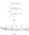
- the DCI may undergo a number of processes, as illustrated in FIG. 1 .
- the processes may include the attachment of a cyclic redundancy check 102 used for error detection in the DCI message; channel coding 104 for use in forward error correction, and rate matching 106 that is used to output a bit stream with a desired code rate.
- Detailed instructions for performing the cyclic redundancy check, channel coding, and rate matching are provided in the 3GPP LTE specifications, such as Release 8, 9 and 10.
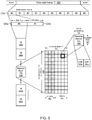
- the encoded DCI message(s) for each control channel may then be multiplexed and scrambled before undergoing modulation, layer mapping, precoding and resource mapping, as illustrated in the block diagram of FIG. 2 .
- Blocks of encoded bits for each control channel may be multiplexed 202, e.g., by a multiplexer, to create a block of data.
- the size of the blocks of data may be altered to ensure that PDCCHs start at a desired CCE position.
- the size of the blocks of data may also be altered to ensure that the blocks of bits match the amount of REGs that can be used by the PDCCH.
- the multiplexed block of bits may then be scrambled.
- One scrambling process that is currently used is the use of a bit-wise XOR operation with a cell specific scrambling sequence. Other types of scrambling may be used as well.
- the encoding process is outlined in the 3GPP LTE specification.
- the scrambled bits may then undergo modulation 204, e.g., by a modulating module.
- Quadrature Phase Shift Keying QPSK is often used to create a block of complex-valued modulation symbols.
- other types of modulation such as Bi-Phase Shift Keying (BPSK), 16 Quadrature Amplitude Modulation (16-QAM), 32-QAM, 64-QAM, and so forth may also be used.
- BPSK Bi-Phase Shift Keying
- 16-QAM 16 Quadrature Amplitude Modulation
- 32-QAM 32-QAM
- 64-QAM 64-QAM
- the complex symbols may be mapped 206, e.g., by a layer mapping module, to multiple layers, depending on a number of transmit antennas used at the eNode B.
- a layer mapping module e.g., a layer mapping module
- One, two or four layer mapping has been used in legacy systems. Additional layers, such as eight layer mapping may also be used.
- the mapping process is outlined in the 3GPP LTE specification.
- a precoder 208 may take a block from the layer mapper 206 to generate an output for each antenna port.
- Precoding for transmission diversity may be performed for two or four antennas in legacy systems based on the 3GPP LTE Rel. 8 specification. Transmission diversity for more complex systems, such as an eNode B with eight antennas, may also be applied using precoding.
- One scheme used for precoding includes the Alamouti scheme for two antennas.
- the complex valued symbols for each antenna may then be divided into groups for mapping 210, e.g., by a resource mapping module, to resource elements.
- the complex valued symbols for each antenna may be divided into quadruplets.
- the sets of quadruplets may then undergo a permutation such as interleaving and cyclic shifting before being mapped to resource elements within resource element groups.
- the PDCCH may be transmitted prior to the PDSCH in each subframe transmitted from the eNode B to the UE.
- the demodulation of the PDCCH at the UE may be based on a cell-specific reference signal (CRS).
- CRS cell-specific reference signal
- Each cell is only assigned a single reference signal.
- the use of the single CRS may limit the number of nodes that can be deployed in a cell.
- a UE may receive a PDCCH using blind decoding.
- the resources used by the UE for PDCCH blind decoding may be referred to as the search space.
- a different search space may be used to detect and demodulate an ePDCCH for a UE specific reference signal (UE-RS) relative to the use of a CRS.
- UE-RS UE specific reference signal
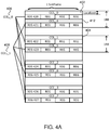
- the signal on the physical (PHY) layer used to convey the PDCCH may be transmitted by the eNode B (enhanced Node B or evolved Node B or eNB) to the user equipment (UE) using a generic long term evolution (LTE) frame structure, as illustrated in FIG. 3 .
- LTE long term evolution
- a radio frame 300 may have a duration, T f , of 10 milliseconds (ms). Each radio frame may be segmented or divided into ten subframes 310i that are each 1 ms long. Each subframe may be further subdivided into two slots 320a and 320b, each with a duration, T slot , of 0.5 ms.
- the first slot (#0) 320a may include a physical downlink control channel (PDCCH) 360 and a physical downlink shared channel (PDSCH) 366
- the second slot (#2) 320b may include data using the PDSCH.
- Each slot for a component carrier (CC) used by the eNode B and the UE may include multiple resource blocks (RBs) 330a, 330b, 330i, 330m, and 330n based on the CC frequency bandwidth.
- CC component carrier
- Each RB 330i may include 12 - 15kHz subcarriers 336 (on the frequency axis) and 6 or 7 orthogonal frequency-division multiplexing (OFDM) symbols 332 (on the time axis) per subcarrier.
- the RB may use seven OFDM symbols if short or normal cyclic prefix is employed.
- the RB may use six OFDM symbols if an extended cyclic prefix is used.
- the resource block may be mapped to 84 resource elements (REs) 340i using short or normal cyclic prefixing, or the resource block may be mapped to 72 REs (not shown) using extended cyclic prefixing.
- REs resource elements
- the RE may be a unit of one OFDM symbol 342 by one subcarrier (e.g., 15kHz) 346.
- Each RE may transmit two bits 350a and 350b of information using QPSK. The actual number of bits communicated per RE is dependent on the level of modulation used.
- the control region of each legacy serving cell in carrier aggregation consists of a set of (CCEs).
- the CCEs may be numbered from 0 to N CCE,k -1, where N CCE,k is the total number of CCEs in the control region of subframe k.
- the UE may monitor a set of PDCCH candidates on one or more activated serving cells as configured by higher layer signaling for control information.
- the term monitoring may imply attempting, at the UE, to decode each of the PDCCH candidates in the set according to all of the monitored DCI formats.
- the UE may utilize one or more CCEs to monitor a PDCCH in the set.
- a physical control channel may be transmitted on an aggregation of one or several CCEs.
- the CCE(s) may be transmitted consecutively.
- one example control channel element may correspond to nine resource element groups (REGs).
- Each legacy REG comprises four resource elements.
- N REG the number of REGs that are not assigned to a physical control format indicator channel (PCFICH) or a physical hybrid automatic repeat request (ARQ) indicator channel (PHICH) is denoted N REG .
- the PDCCH may support multiple formats. Multiple PDCCHs may be transmitted in a subframe.
- PDCCH formats is provided in the following table.
- the currently described PDCCH transmission and mapping process may create limitations to advances that are made in other areas of wireless communication. For example, mapping of CCEs to subframes in OFDM symbols may spread over the control region to provide spatial diversity.
- future networks may be configured HetNets that can include a number of different kinds of transmission nodes in a single macro cell serving area. More UEs can be served simultaneously by macro and pico cells in the HetNet.
- the 3GPP LTE Rel. 8 PDCCH is designed to demodulate based on cell-specific reference signals, which makes it difficult to fully explore cell splitting gain.
- the PDCCH design may not be adequate to convey the information needed to allow a UE to take advantage of the multiple transmission nodes in the HetNet to increase bandwidth and decrease battery usage at the UE.
- MU-MIMO multi-user multiple-input multiple-output
- M2M machine to machine communication
- PDSCH transmission in a multicast ⁇ broadcast single-frequency network and cross carrier scheduling in carrier aggregation can require increased capacity for the PDCCH.
- the use of UE specific reference signals in PDCCH demodulation at the UE can allow the use of multiple nodes in a HetNet. Rather than relying on a single common reference symbol for an entire cell, each reference symbol may be UE specific to provide a beam forming diversity and a cell splitting gain.
- interference coordination with neighboring cells may use the mapping procedures to guarantee orthogonality among neighboring cells, thereby reducing or avoiding subcarrier collisions.
- the capacity of the ePDCCH design may be increased for future networks.
- an enhanced PDCCH may be configured with increased capacity to allow advances in the design of cellular networks and to minimize currently known challenges.
- the examples of ePDCCH design and mapping principals are not intended to be limiting. Because of the broad design aspects of a ePDCCH, including but not limited to CRC attachment, channel coding, rate matching, multiplexing, scrambling, modulation, layer mapping, precoding, resource mapping, and search space requirements, the examples provided are not intended to limit to a certain system. However, the examples can provide improvements upon which other aspects of an ePDCCH design and implementation can be expanded on.
- a relay physical downlink control channel (R-PDCCH) design with non-interleaved UE-RS based mapping may be used for ePDCCH design to achieve scheduling and a beamforming gain when channel state information (CSI) feedback is available.
- the ePDCCH design may base on a non-cross-interleaved R-PDCCH design. however, in some embodiments, the R-PDCCH design that is limited to a relay-specific restriction may not be required ePDCCH design to provide higher scheduling flexibility at eNB, e.g., in the scenario where downlink-uplink traffic has an imbalance.
- a UE may monitor resource blocks in both slots for downlink assignment and uplink grant.
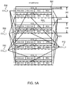
- FIG. 4A provides an example of enhanced channel control elements (eCCEs) indexing for an aggregation level (AGGL) of one.
- the aggregation level of one may imply that the DCI information in an ePDCCH candidate is able to be mapped to a single CCE.
- each resource block pair may comprise two resource blocks, each having the same subcarriers, located in a first and second slot in a subframe of a radio frame, as shown in FIG. 3 .
- CCE L may represent a localized eCCE and CCE D may represent a distributed eCCE.
- there are four CCEs in one RB pair there are four CCEs in one RB pair; however, in some embodiments, a different number of CCEs can be in one RB pair (e.g, 2 or any other number based system requirement).
- a localized ePDCCH may be mapped to a localized eCCE 402 that may further be mapped in frequency and time to a fixed number of resource element groups (REGs), e.g., 4 REGs, in a single resource block pair.
- REGs resource element groups
- the number of REGs in a single resource block pair may vary based on DCI data load requirements (e.g., the amount of DCI data), or other competing requirements in the resource block, such as PCFICH requirements, PHICH requirements, and resource symbol requirements for data allocated within each resource block.
- Each REG may include a plurality of resource elements (e.g. 9).
- the resource elements to which the localized eCCE 402 is mapped to in the resource block pair may be contiguous in time and/or frequency. Alternatively, the resource elements may be separated in time and/or frequency.
- the localized eCCE 402 may be mapped across a slot boundary in the physical resource block pair.
- random beam forming diversity, interference coordination with neighboring cells may be further considered for ePDCCH design.
- a distributed ePDCCHs having the same aggregation level may be mapped to one or more distributed eCCEs that may further be mapped to a plurality of REGs distributed in different resource block pairs.
- the distributed eCCEs 406 may be mapped to a plurality of REGs that are distributed in different resource block pairs.
- the distributed eCCEs for different distributed ePDCCHs belonging to the same aggregation level may be separated as far as possible, as shown in FIG. 4A .
- the frequency separation of the REGs can provide frequency diversity gain. Multiple REGs in a distributed eCCE may be mapped to several separate resource block pairs, although more than one REG may be mapped to a single resource block pair. The more widely distributed REGs may lead to greater diversity gain.
- a R-PDCCH design with no cross-interleaving may also be utilized for distributed CCE to RE mapping.
- the distributed ePDCCH design can use UE-RS instead of CRS to be mapped in the RBs for distributed eCCE mapping of ePDCCH decoding.
- the ePDCCH design may allow a great scheduling flexibility.
- UEs may be configured to monitor the set of RBs in both slots for downlink assignment and uplink grant.
- the ePDCCH may be decoded based on UE-RS and the REGs in different RBs may be precoded by different precoder to realize random beamforming gain and achieve spatial domain diversity.
- the precoder for each RB pair or RB pair bundling may be predefined or randomly selected by an eNB.
- a distributed ePDCCH having an aggregation level of one may be mapped to a distributed eCCE.
- the aggregation level of one may represent that the DCI information is able to be mapped to a single distributed eCCE, e.g., 406 or 408.
- a distributed eCCE may contain, e.g., four REGs that may be mapped to resource blocks in a subframe that are separated in frequency as much as possible, depending on the channel profile and system bandwidth to provide frequency diversity gain.
- the distributed eCCE 406 may contain four REGs. However, a lesser or a greater number of REGs may be used in each distributed eCCE.
- the REGs in the distributed eCCE 406 may be mapped to resource blocks in a subframe that are separated in frequency, depending on the channel profile and system bandwidth to provide frequency diversity gain.
- the REGs for the distributed eCCE 408 may be distributed in frequency.
- the REGs in distributed eCCE 406 and distributed eCCE 408 may have the same distribution or different distribution amongst resource blocks in a subframe.
- the distributed eCCE 406 may be mapped to four REGs 420, 422, 424 and 426 that locate in different physical resource block (PRB) pairs and the distributed eCCE 408 may be mapped to four REGs 421, 423, 425 and 427 that locate in different PRB pairs.
- PRB physical resource block
- a distributed eCCE may be mapped to REGs in a subframe that are separated in frequency as much as possible, depending on the channel profile and system bandwidth to provide frequency diversity gain.
- each distributed eCCE 406 and 408 are each shown to be in the same time position within a resource block pair, this is not required for each respective distributed eCCE.
- the distributed REGs in distributed eCCE 406 and eCCE 408 may be in a different temporal location within a resource block pair.
- Each distributed eCCE in a subframe may have a same number of REGs or a different number of REGs.
- distributed eCCE 406 may have four REGs 420, 422, 424 and 426 and distributed eCCE 408 may have four REGs 421, 423, 425 and 427.
- the localized eCCEs and the distributed eCCEs may be indexed independently. For example, as shown in Fig.1 , the localized eCCEs and the distributed eCCEs are indexed beginning from zero; however, in some embodiments, the localized eCCEs and the distributed eCCEs may be indexed differently. In one embodiment, a ratio of localized eCCEs to distributed eCCEs in one PRB pair may be configured by high layer signaling, e.g., via radio resource control (RRC) signaling from eNB.
- RRC radio resource control
- the ratio of localized eCCEs to distributed eCCEs may be 2:2, 3:1, 1:3, 4:0 or 0:4.
- the ratio of common search space may be set to be fixed, e.g., 0:4 with zero localized eCCE and four distributed eCCEs.
- the ratio of localized to distributed eCCEs may be used, by the UE, to implicitly indicate the ratio of localized and distributed ePDCCH candidates that UE should search.
- the ratio of localized and distributed candidates that UE should search may be indicated through RRC signaling.
- an eNB may adjust the ratio of localized and distributed candidates that UE should search based on, e.g., a control channel quality. For example, more localized eCCEs than distributed eCCEs may be configured for a better channel quality.
- FIG. 4B illustrates an example of enhanced channel control elements (eCCEs) for ePDCCH with an aggregation level (AGGL) of two.
- CCE L represents a localized eCCE
- eCCE D represents a distributed eCCE.
- a localized ePDCCH having aggregation level of two may be mapped to two separate localized eCCEs, e.g., 402 and 412 in a resource block pair; however, in some embodiments, the two localized eCCEs 402 and 412 may be contiguous eCCEs in the resource block pair.
- a distributed ePDCCH having aggregation level of two may be mapped to distributed eCCEs, e.g., 406 and 408.
- the aggregation level may be considered in localized eCCE indexing.
- An aggregation level specific localized eCCE indexing may be used to achieve scheduling gain.
- FIGs. 4A and 4B show logical localized eCCE indexing for AGGLs of one and two, respectively.
- a logical index may be mapped to a physical index in the examples.
- physical eCCEs may be indexed in frequency increasing order while logical index for eCCEs may be AGGL specifically mapped to the physical index.
- logical indexes for localized eCCEs with AGGL one may be distributed in four PRB pairs instead of simply increased in frequency domain.
- the localized eCCE 402 in FIG. 4A may have an index of CCE L _0.
- the localized eCCE 412 that is in the same PRB pair as the localized eCCE 402 may be indexed as CCE L _4.
- More scheduling gain may be obtained based on a bigger offset in the logical indexes for localized eCCEs. For example, a different scheduling gain may be obtained with the localized eCCE 402 indexed as 0 and localized eCCE 412 indexed as 2, 3, 5, 6 or 7, etc.
- FIG. 4B shows an example of logical localized eCCE indexes used for AGGL two.
- a localized ePDCCH with an aggregation level of two may be mapped to two localized eCCEs, e.g., 402 and 412 in a resource block pair.
- the logical indexes for the two localized eCCEs 402 and 412 for the same localized ePDCCH may be increased in frequency domain.
- the localized eCCE 402 may be indexed from zero and the localized eCCE 412 may have index of one.
- the localized eCCE 404 and 414 that are used for the same ePDCCH transmission or ePDCCH candidates decoding may be indexed as 2 (CCE L _2) and 3 (CCE L _3), respectively.
- FIGs. 5A and 5B illustrates examples of logical distributed eCCE indexing for distributed eCCEs.
- logical distributed eCCE indexing may take Inter-Cell Interference Coordination (ICIC) into consideration.
- the distributed eCCE indexes belonging to the search space for a given AGGL may distribute across different ICIC coordinate region to maximize the ICIC gain.
- each REG in a distributed eCCE may be separated in frequency from other REGs in the eCCE to gain frequency diversity.
- FIG.5A takes eCCEs with AGGL one as an example.
- an ICIC coordinate region in each PRB pair may equal to one equivalent eCCE L in the PRB pair.
- FIG. 5A illustrates each PRB pair may comprise two ICIC coordinate regions, a different number of ICIC coordinate regions may be present in a PRB pair.
- the first eNB in response to determining , by a first eNB, that a neighboring cell of a second eNB uses a first coordinate region for ePDCCH transmission, the first eNB may blank the first coordinate region and use a second coordinate region for the current cell of the first eNB for ePDCCH transmission to reduce inter-cell interference among neighboring cells.
- FIG. 5A in response to determining , by a first eNB, that a neighboring cell of a second eNB uses a first coordinate region for ePDCCH transmission, the first eNB may blank the first coordinate region and use a second coordinate region for the current cell of
- the first eNB may not use coordinate region 520 but use coordinate region 521 for ePDCCH transmission and thus the distributed eCCEs may be located in the same coordinate region 521.
- logical distributed CCE D _0 506 and eCCE D _1 508 may be distributed in different ICIC coordinate regions.
- CCE D _0 506 may be distributed in a first ICIC coordinate region 520 that is represented by a dotted line in FIG. 5A .
- CCE D _1 506 may be distributed in a second ICIC coordinate region 521 that is represented by a dot dash line in FIG. 5A .
- FIG.5B may be used for eCCEs with AGGL two. In FIG. 5B , two distributed eCCEs 506 and 508 for the same ePDCCH are distributed in the same first ICIC coordinate region 520. And, two distributed eCCEs 510 and 512 for the same ePDCCH are in the same second ICIC coordinate region 521.
- AGGL specific logical indexing may be used for distributed eCCEs.
- the distributed ePDCCH that belong to a search space for a given AGGL may distribute across different ICIC coordinate regions as possible.
- the example of FIG. 5A shows that the distributed eCCE 506 may be indexed as CCE D _0 that is distributed in ICIC coordinate region 520, the distributed eCCE 508 may be indexed as CCE D _1 that is distributed in ICIC coordinate region 521, the distributed eCCE 510 may be indexed as CCE D _2 that is distributed in ICIC coordinate region 520 while the distributed eCCE 512 may be indexed as CCE D _3 that is distributed in ICIC coordinate region 521.
- FIG. 5A shows that the distributed eCCE 506 may be indexed as CCE D _0 that is distributed in ICIC coordinate region 520, the distributed eCCE 508 may be indexed as CCE D _1 that is distributed in ICIC coordinate region
- 5B shows that the distributed eCCEs 506 and 508 for a first ePDCCH may be indexed as CCE D _0 and CCE D _1, respectively that are distributed in the same ICIC coordinate regions 520 while distributed eCCEs 510 and 512 mapped to a second ePDCCH may be indexed as CCE D _2 and CCE D _3 that are distributed in the same ICIC coordinate region 521.
- the physical eCCE indexes may be used for eNB to implicitly derive physical downlink control channel (PUCCH) indexes to reduce PUCCH indexing ambiguity.
- the logical eCCE indexes may be used, by UE, for ePDCCH resource allocation and blind decoding to achieve scheduling gain and ICIC scheduling gain.
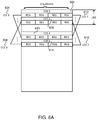
- FIG. 6A and 6B provide examples wherein localized eCCEs and distributed eCCEs can be indexed globally. Similar to the embodiments as mentioned previously with regard to FIGs. 4A , 4B , 5A and 5B , the ratio of localized eCCEs to distributed eCCEs in one PRB pair can also be configured by high layer signaling, e.g., RRC signaling from eNB.
- the global logical eCCE indexing as shown in FIGs. 6A and 6B may be aggregation level specific to include both localized and distributed ePDCCH candidates in UE's search space. In one embodiment, the localized ePDCCH candidate and the distributed ePDCCH candidates may be interleaved with each other.
- the indexes for the eCCEs may begin from, e.g., 0.
- the localized eCCEs 602, 606, 610, 614 may be indexed as CCE 0, CCE 2, CCE 4, and CCE 6, respectively.
- the distributed eCCEs 604, 608, 612, 616 may be indexed as CCE 1, CCE 3, CCE 5, and CCE 7, respectively.
- the indexes for the eCCEs may also begin from, e.g., 0, although this may not be required.
- the localized eCCEs 602 and 604 for a first ePDCCH candidate may be indexed as CCE 0 and CCE 1, respectively; the distributed eCCEs 606 and 608 for a second ePDCCH candidate may be indexed as CCE 2 and CCE 3, respectively; the localized eCCEs 610, 612 may be indexed as CCE 4 and CCE 5, respectively; and the distributed eCCEs 614 and 616 may be indexed as CCE 6 and CCE 7, respectively.
- the AGGL specific logical eCCE indexing as shown in FIGs. 6A and 6B can be used for ePDCCH assignment and blind decoding.
- physical eCCEs as shown in the examples of FIGs. 6A and 6B can be used for implicit PUCCH index derivation.
- the logical eCCEs indexing of FIGs. 6A and 6B may take ICIC coordinate region into consideration, similar to the examples as discussed previously with regard to FIGs. 5A and 5B .
- different ePDCCHs belonging to the same AGGL may be distributed in different ICIC coordinate regions as possible.
- distributed eCCEs 604 and 608 may be in different coordinate regions while distributed eCCEs 612 and 616 may be in different coordinate regions.
- distributed eCCEs 606, 608 mapping to the same ePDCCH may be in the same coordinate region which is different from the coordinate region where distributed eCCEs 614, 608 are located. While FIGs. 6A and 6B illustrate an embodiment of a number of eCCEs, some embodiments may have a different number of eCCEs.
- FIG. 7 shows an example of localized and distributed independent eCCE indexing.
- the eCCE indexing may also be described with reference to FIGs. 4A , 4B , 5A and 5B .
- an eNB may map modulated symbols in each ePDCCH at least one eCCEs.
- the eNB may determine or adjust a ratio of localized eCCEs and distributed eCCEs in a search space of the ePDCCH, e.g., based on a quality of the control channel.
- the eNB may indicate a ratio of the localized ePDCCH candidates and the distributed ePDCCH candidates that UE should search by the ratio of localized eCCEs and distributed eCCEs in the search space, as determined in block 720.
- the eNB may perform an aggregation level specific logical indexing for localized eCCEs. For example, the eNB may perform logical indexing for localized eCCEs with aggregation level of one, as shown in FIGs. 4A and 5A . The eNB may perform logical indexing for localized eCCEs with aggregation level of two, as shown in FIGs. 4B and 5B .
- eNB may perform an aggregation level specific logical indexing for distributed eCCEs.
- FIGs. 4A and 5A show the examples of AGGL one and FIGs. 4B and 5B show the examples of AGGL two.
- eNB may further implicitly derive PUCCH indexes based on physical eCCE indexes that are mapped to the logical eCCE indexes.
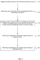
- FIG. 8 shows an example of global localized and distributed eCCE indexing.
- the eCCE indexing may also be described with reference to FIGs. 6A and 6B .
- an eNB may map modulated symbols in each ePDCCH to at least one eCCEs.
- the eNB may detemine a ratio of localized eCCEs and distributed eCCEs in a search space of the ePDCCH, e.g., based on a quality of the control channel.
- the eNB may indicate a ratio of the localized ePDCCH candidates and the distributed ePDCCH candidates that UE should search by the ratio of localized eCCEs and distributed eCCEs in the search space, as determined in block 820.
- the eNB may perform an aggregation level specific logical indexing for localized and distributed eCCEs. For example, the eNB may interleave indexed for the localized eCCEs and the distributed eCCEs, as shown in FIGs. 6A and 6B . Further, in block 750, the eNB may further utilize ICIC coordinate regions as shown in FIGs. 5A and 5B for the logical indexing for distributed eCCEs.
- FIG. 9 provides an example illustration of a mobile device, such as a user equipment (UE), a mobile station (MS), a mobile wireless device, a mobile communication device, a tablet, a handset, or other type of mobile wireless device.
- the mobile device may include one or more antennas configured to communicate with a base station (BS), an evolved Node B (eNB), or other type of wireless wide area network (WWAN) access point. While two antennas are shown, the mobile device may have between one and four or more antennas.
- the mobile device may be configured to communicate using at least one wireless communication standard including Third Generation Partnership Project Long Term Evolution (3GPP LTE), Worldwide interoperability for Microwave Access (WiMAX), High Speed Packet Access (HSPA), Bluetooth, WiFi, or other wireless standards.
- 3GPP LTE Third Generation Partnership Project Long Term Evolution
- WiMAX Worldwide interoperability for Microwave Access
- HSPA High Speed Packet Access
- WiFi WiFi
- the mobile device may communicate using separate antennas for each wireless communication standard or shared antennas for multiple wireless communication standards.
- the mobile device may communicate in a wireless local area network (WLAN), a wireless personal area network (WPAN), and/or a wireless wide area network (WWAN).
- WLAN wireless local area network
- WPAN wireless personal area network
- WWAN wireless wide area network
- FIG. 9 also provides an illustration of a microphone and one or more speakers that may be used for audio input and output from the mobile device.
- the display screen may be a liquid crystal display (LCD) screen, or other type of display screen such as an organic light emitting diode (OLED) display.
- the display screen may be configured as a touch screen.
- the touch screen may use capacitive, resistive, or another type of touch screen technology.
- An application processor and a graphics processor may be coupled to internal memory to provide processing and display capabilities.
- a non-volatile memory port may also be used to provide data input/output options to a user.
- the non-volatile memory port may also be used to expand the memory capabilities of the mobile device.
- a keyboard may be integrated with the mobile device or wirelessly connected to the mobile device to provide additional user input.
- a virtual keyboard may also be provided using the touch screen.
- FIG. 10 provides an example illustration of communication between an eNB 1002 and a mobile device 1012, such as a user equipment (UE), a mobile station (MS), a mobile wireless device, a mobile communication device, a tablet, a handset, or other type of mobile wireless device.
- a description on the mobile device 1012 may refer to the embodiments as mentioned with regard to Fig. 9 .
- the mobile device 1012 may include one or more antennas configured to communicate with a base station (BS), an evolved Node B (eNB), or other type of wireless wide area network (WWAN) access point via a network 1014.
- BS base station
- eNB evolved Node B
- WWAN wireless wide area network
- FIG. 10 also provides an illustration of an eCCE indexing module 1004 that may be coupled to a resource mapping module 1006.
- eNB 1002 may comprise additional modules.
- the eCCE indexing module 1004 may be configured to provide indexes for eCCEs in a search space of ePDCCH, e.g., as shown in FIGs. 7 and 8 .
- the resource mapping module 1006 may perform resource mapping to form a search space for ePDCCH, to be transmitted to the mobile device 1012.
- the information on the eCCEs in the search space may be transmitted by the eNB 1002 to the mobile device 1012 via RRC signaling for long term adjustment or SIB signaling for short term adjustment.
- the UE 1012 may use the RRC signaling and SIB signaling to perform ePDCCH blind decoding based on the corresponding search space.
- the mobile device 1012 may comprise an eCCE de-indexing module 1016 that may obtain or de-index the eCCE indexes based on the indexing as mentioned above with regard to FIGs. 4A , 4B , 5A , 5B , 6A , 6B , 7 and 8 .
- the ePDCCH assignment and blind decoding module 1018 may use the obtained eCCE indexes from module 1016 to perform ePDCCH blind decoding and ePDCCH assignment and/or resource allocation; in some embodiments, module 1018 may be divided into several modules. While two modules are shown in the mobile device 1012, in some embodiments, the mobile device 1012 may comprise any other modules.
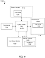
- FIG. 11 illustrates, for one embodiment, an example system 1100 comprising one or more processor(s) 1104, system control logic 1108 coupled with at least one of the processor(s) 1104, system memory 1112 coupled with system control logic 1108, non-volatile memory (NVM)/storage 1116 coupled with system control logic 1108, and a network interface 1120 coupled with system control logic 1108.
- processor(s) 1104 system control logic 1108 coupled with at least one of the processor(s) 1104, system memory 1112 coupled with system control logic 1108, non-volatile memory (NVM)/storage 1116 coupled with system control logic 1108, and a network interface 1120 coupled with system control logic 1108.
- NVM non-volatile memory
- Processor(s) 1104 may include one or more single-core or multi-core processors.
- Processor(s) 1104 may include any combination of general-purpose processors and dedicated processors (e.g., graphics processors, application processors, baseband processors, etc.).
- processors(s) 1104 may include processor module and be configured to execute the embodiments of Figures 1-10 in accordance with various embodiments.
- processor(s) 1104 may include module 1004 and 1006.
- System control logic 1108 may include any suitable interface controllers to provide for any suitable interface to at least one of the processor(s) 1104 and/or to any suitable device or component in communication with system control logic 1108.
- System control logic 1108 may include one or more memory controller(s) to provide an interface to system memory 1112.
- System memory 1112 may be used to load and store data and/or instructions, for example, for system 1100.
- System memory 1112 for one embodiment may include any suitable volatile memory, such as suitable dynamic random access memory (DRAM), for example.
- DRAM dynamic random access memory
- NVM/storage 1116 may include one or more tangible, non-transitory computer-readable media used to store data and/or instructions, for example.
- NVM/storage 1116 may include any suitable non-volatile memory, such as flash memory, for example, and/or may include any suitable non-volatile storage device(s), such as one or more hard disk drive(s) (HDD(s)), one or more compact disk (CD) drive(s), and/or one or more digital versatile disk (DVD) drive(s), for example.
- HDD hard disk drive
- CD compact disk
- DVD digital versatile disk
- the NVM/storage 1116 may include a storage resource physically part of a device on which the system 1100 is installed or it may be accessible by, but not necessarily a part of, the device. For example, the NVM/storage 1116 may be accessed over a network via the network interface 1120.
- System memory 1112 and NVM/storage 1116 may respectively include, in particular, temporal and persistent copies of instructions 1124.
- Instructions 1124 may include instructions that when executed by at least one of the processor(s) 1104 result in the system 1100 implementing a one or both of methods 400 and 700 as described herein.
- instructions 1124, or hardware, firmware, and/or software components thereof may additionally/alternatively be located in the system control logic 1108, the network interface 1120, and/or the processor(s) 1104.
- Network interface 1120 may have a transceiver 1122 to provide a radio interface for system 1100 to communicate over one or more network(s) and/or with any other suitable device.
- the transceiver 1122 may be implement a receiver module and/or a transmitter module.
- the transceiver 1122 may be integrated with other components of system 1100.
- the transceiver 1122 may include a processor of the processor(s) 1104, memory of the system memory 1112, and NVM/Storage of NVM/Storage 1116.
- Network interface 1120 may include any suitable hardware and/or firmware.
- Network interface 1120 may include a plurality of antennas to provide a multiple input, multiple output radio interface.
- Network interface 1120 for one embodiment may include, for example, a network adapter, a wireless network adapter, a telephone modem, and/or a wireless modem.
- At least one of the processor(s) 1104 may be packaged together with logic for one or more controller(s) of system control logic 1108.
- at least one of the processor(s) 1104 may be packaged together with logic for one or more controllers of system control logic 1108 to form a System in Package (SiP).
- SiP System in Package
- at least one of the processor(s) 1104 may be integrated on the same die with logic for one or more controller(s) of system control logic 1108.
- at least one of the processor(s) 1104 may be integrated on the same die with logic for one or more controller(s) of system control logic 1108 to form a System on Chip (SoC).
- SoC System on Chip
- the system 1100 may further include input/output (I/O) devices 1132.
- the I/O devices 1132 may include user interfaces designed to enable user interaction with the system 1100, peripheral component interfaces designed to enable peripheral component interaction with the system 1100, and/or sensors designed to determine environmental conditions and/or location information related to the system 1100.
- the user interfaces could include, but are not limited to, a display (e.g., a liquid crystal display, a touch screen display, etc.), a speaker, a microphone, one or more cameras (e.g., a still camera and/or a video camera), a flashlight (e.g., a light emitting diode flash), and a keyboard.
- a display e.g., a liquid crystal display, a touch screen display, etc.
- a speaker e.g., a microphone
- one or more cameras e.g., a still camera and/or a video camera
- a flashlight e.g., a light emitting diode flash
- the peripheral component interfaces may include, but are not limited to, a non-volatile memory port, an audio jack, and a power supply interface.
- the sensors may include, but are not limited to, a gyro sensor, an accelerometer, a proximity sensor, an ambient light sensor, and a positioning unit.
- the positioning unit may also be part of, or interact with, the network interface 1120 to communicate with components of a positioning network, e.g., a global positioning system (GPS) satellite.
- GPS global positioning system
- system 1100 may be a mobile computing device such as, but not limited to, a laptop computing device, a tablet computing device, a netbook, a mobile phone, etc.
- system 1100 may have more or less components, and/or different architectures.
- modules may be implemented as a hardware circuit comprising custom VLSI circuits or gate arrays, off-the-shelf semiconductors such as logic chips, transistors, or other discrete components.
- a module may also be implemented in programmable hardware devices such as field programmable gate arrays, programmable array logic, programmable logic devices or the like.
- Modules may also be implemented in software for execution by various types of processors.
- An identified module of executable code may, for instance, comprise one or more physical or logical blocks of computer instructions, which may, for instance, be organized as an object, procedure, or function. Nevertheless, the executable code of an identified module need not be physically located together, but may comprise disparate instructions stored in different locations which, when joined logically together, comprise the module and achieve the stated purpose for the module.
- a module of executable code may be a single instruction, or many instructions, and may even be distributed over several different code segments, among different programs, and across several memory devices.
- operational data may be identified and illustrated herein within modules, and may be embodied in any suitable form and organized within any suitable type of data structure. The operational data may be collected as a single data set, or may be distributed over different locations including over different storage devices, and may exist, at least partially, merely as electronic signals on a system or network.
- the modules may be passive or active, including agents operable to perform desired functions.
- FIGs. 1, 2 , 7 and 8 is illustrated to comprise a sequence of processes, the methods in some embodiments may perform illustrated processes in a different order.
Landscapes
- Engineering & Computer Science (AREA)
- Signal Processing (AREA)
- Computer Networks & Wireless Communication (AREA)
- Quality & Reliability (AREA)
- Computer Security & Cryptography (AREA)
- Databases & Information Systems (AREA)
- Computing Systems (AREA)
- General Engineering & Computer Science (AREA)
- Business, Economics & Management (AREA)
- General Business, Economics & Management (AREA)
- Multimedia (AREA)
- Computer Hardware Design (AREA)
- Mobile Radio Communication Systems (AREA)
Claims (15)
- Appareil destiné à être mis en œuvre dans un équipement d'utilisateur (UE), l'appareil comprenant :un moyen permettant de recevoir un message de contrôle des ressources radio (RRC) comprenant un rapport entre des éléments de canal de contrôle améliorés (ECCE) localisés (402, 412) et des ECCE distribués (406, 408) dans une paire de blocs de ressources de l'espace de recherche d'un canal de contrôle physique en liaison descendante amélioré (EPDCCH) ;un moyen permettant de déterminer, sur la base dudit rapport, un ensemble d'EPDCCH localisés candidats et un ensemble d'EPDCCH distribués candidats à surveiller dans l'espace de recherche, l'espace de recherche étant spécifique d'un UE ; etun moyen permettant de réaliser une tentative de décodage sur l'ensemble d'EPDCCH localisés candidats et l'ensemble d'EPDCCH distribués candidats afin d'obtenir une information de contrôle en liaison descendante (DCI).
- Appareil selon la revendication 1, dans lequel la circuiterie moyen permettant de déterminer l'ensemble d'EPDCCH localisés candidats et l'ensemble d'EPDCCH distribués candidats à surveiller sur la base en outre d'un niveau d'agrégation de l'EPDCCH.
- Appareil selon la revendication 2, dans lequel l'ensemble d'EPDCCH localisés candidats comprend un ensemble d'ECCE localisés parmi une pluralité d'ECCE localisés, et l'ensemble d'EPDCCH distribués candidats comprend un ensemble d'ECCE distribués parmi une pluralité d'ECCE distribués.
- Appareil selon la revendication 3, dans lequel la pluralité d'ECCE localisés sont numérotés de 0 à NECCE,p1,k-1, où NECCE,p1,k est un nombre total d'ECCE dans la pluralité d'ECCE localisés d'une sous-trame k, et dans lequel la pluralité d'ECCE distribués sont numérotés de 0 à NECCE,p2,k-1, où NECCE,p2,k est un nombre total d'ECCE dans la pluralité d'ECCE distribués de la sous-trame k.
- Appareil selon l'une quelconque des revendications 3 et 4, dans lequel la pluralité d'ECCE localisés et la pluralité d'ECCE distribués sont situés dans une ou plusieurs paires de blocs de ressources physiques (PRB).
- Procédé destiné à être réalisé par un équipement d'utilisateur (UE), le procédé consistant à :recevoir un message de contrôle des ressources radio (RRC) comprenant un rapport entre des éléments de canal de contrôle améliorés (ECCE) localisés (402, 412) et des ECCE distribués (406, 408) dans une paire de blocs de ressources de l'espace de recherche d'un canal de contrôle physique en liaison descendante amélioré (EPDCCH) ;déterminer, sur la base dudit rapport, un ensemble d'EPDCCH localisés candidats et un ensemble d'EPDCCH distribués candidats à surveiller dans l'espace de recherche, l'espace de recherche étant spécifique d'un UE ; etréaliser une tentative de décodage sur les EPDCCH localisés candidats et sur les EPDCCH distribués candidats afin d'obtenir une information de contrôle en liaison descendante (DCI).
- Procédé selon la revendication 6, dans lequel l'ensemble d'EPDCCH localisés candidats comprend un ensemble d'ECCE localisés parmi une pluralité d'ECCE localisés, et l'ensemble d'EPDCCH distribués candidats comprend un ensemble d'ECCE distribués parmi une pluralité d'ECCE distribués, et dans lequel l'ensemble d'EPDCCH localisés candidats et l'ensemble d'EPDCCH distribués candidats sont dans une ou plusieurs paires de blocs de ressources physiques (PRB).
- Procédé selon la revendication 7, dans lequel la pluralité d'ECCE localisés sont numérotés de 0 à NECCE,p1,k-1, où NECCE,p1,k est un nombre total d'ECCE dans la pluralité d'ECCE localisés d'une sous-trame k, et dans lequel la pluralité d'ECCE distribués sont numérotés de 0 à NECCE,p2,k-1, où NECCE,p2,k est un nombre total d'ECCE dans la pluralité d'ECCE distribués de la sous-trame k.
- Procédé selon l'une quelconque des revendications 6 à 8, dans lequel le nombre d'EPDCCH localisés candidats et le nombre d'EPDCCH distribués candidats à surveiller sont basés sur un niveau d'agrégation de l'EPDCCH.
- Support(s) de stockage lisible(s) par ordinateur, comprenant des instructions, l'exécution des instructions par un ou plusieurs processeurs d'un équipement d'utilisateur amenant l'équipement d'utilisateur à réaliser le procédé selon les revendications 6 à 9.
- Appareil destiné à être mis en œuvre dans un nœud B évolué (eNB), l'appareil comprenant :un moyen permettant de déterminer une mise en correspondance de symboles modulés dans un canal de contrôle physique en liaison descendante amélioré (EPDCCH) avec un ensemble d'EPDCCH localisés candidats et un ensemble d'EPDCCH distribués candidats, pour la transmission d'une information de contrôle en liaison descendante (DCI) ;un moyen permettant de générer un message de contrôle des ressources radio (RRC) comprenant un rapport entre des éléments de canal de contrôle améliorés (ECCE) localisés (402, 412) et des ECCE distribués (406, 408) dans une paire de blocs de ressources de l'espace de recherche de l'EPDCCH, l'espace de recherche étant spécifique d'un équipement d'utilisateur (UE) ; etun moyen permettant de transmettre le message RRC à un UE.
- Appareil selon la revendication 11, comprenant en outre :un moyen permettant de déterminer un niveau d'agrégation de l'EPDCCH, le niveau d'agrégation étant un nombre d'ECCE avec lesquels une DCI doit être mise en correspondance ; etun moyen permettant de définir l'espace de recherche spécifique d'un UE de l'EPDCCH sur la base du niveau d'agrégation, du nombre d'ECCE dans l'EPDCCH localisé et du nombre d'ECCE dans l'EPDCCH distribué.
- Appareil selon la revendication 12, dans lequel l'ensemble d'EPDCCH localisés candidats comprend un ensemble d'ECCE localisés parmi une pluralité d'ECCE localisés, et l'ensemble d'EPDCCH distribués candidats comprend un ensemble d'ECCE distribués parmi une pluralité d'ECCE distribués.
- Appareil selon la revendication 13, dans lequel la pluralité d'ECCE localisés sont numérotés de 0 à NECCE,p1,k-1, où NECCE,p1,k est un nombre total d'ECCE dans la pluralité d'ECCE localisés d'une sous-trame k, et dans lequel la pluralité d'ECCE distribués sont numérotés de 0 à NECCE,p2,k-1, où NECCE,p2,k est un nombre total d'ECCE dans la pluralité d'ECCE distribués de la sous-trame k.
- Appareil selon les revendications 13 et 14, comprenant en outre :
un moyen permettant de mettre en correspondance l'ensemble d'EPDCCH localisés candidats et l'ensemble d'EPDCCH distribués candidats avec une ou plusieurs paires de blocs de ressources physiques (PRB).
Applications Claiming Priority (2)
| Application Number | Priority Date | Filing Date | Title |
|---|---|---|---|
| US201261667325P | 2012-07-02 | 2012-07-02 | |
| PCT/US2013/048949 WO2014008196A1 (fr) | 2012-07-02 | 2013-07-01 | Indexage d'éléments de commande de canal amélioré d'espace de recherche de canal physique de commande de liaison descendante amélioré |
Publications (3)
| Publication Number | Publication Date |
|---|---|
| EP2868017A1 EP2868017A1 (fr) | 2015-05-06 |
| EP2868017A4 EP2868017A4 (fr) | 2016-04-06 |
| EP2868017B1 true EP2868017B1 (fr) | 2019-11-20 |
Family
ID=48953295
Family Applications (1)
| Application Number | Title | Priority Date | Filing Date |
|---|---|---|---|
| EP13813505.8A Active EP2868017B1 (fr) | 2012-07-02 | 2013-07-01 | Signalisation pour l'espace de recherche d'un canal physique de commande de liaison descendante amélioré |
Country Status (12)
| Country | Link |
|---|---|
| EP (1) | EP2868017B1 (fr) |
| JP (3) | JP5964513B2 (fr) |
| KR (3) | KR20160093112A (fr) |
| CN (2) | CN104509008B (fr) |
| AU (1) | AU2013286893B2 (fr) |
| BR (1) | BR112014030149A2 (fr) |
| CA (1) | CA2874902C (fr) |
| HK (1) | HK1251095A1 (fr) |
| MX (1) | MX354765B (fr) |
| MY (1) | MY173113A (fr) |
| RU (2) | RU2652093C1 (fr) |
| WO (1) | WO2014008196A1 (fr) |
Families Citing this family (5)
| Publication number | Priority date | Publication date | Assignee | Title |
|---|---|---|---|---|
| JP6229031B2 (ja) * | 2016-10-06 | 2017-11-08 | 株式会社三共 | 遊技機 |
| CN108811116B (zh) | 2017-05-05 | 2021-03-05 | 华为技术有限公司 | 传输控制信道的方法、网络设备、网络控制器和终端设备 |
| US10992433B2 (en) * | 2017-10-25 | 2021-04-27 | Qualcomm Incorporated | Symbol mapping for a downlink control channel |
| CN110022350A (zh) * | 2019-01-28 | 2019-07-16 | 阿里巴巴集团控股有限公司 | 客户端注册及注册信息的处理方法和装置 |
| CN114070532A (zh) * | 2020-08-07 | 2022-02-18 | 展讯通信(上海)有限公司 | 控制信道元cce索引的确认方法及相关产品 |
Family Cites Families (11)
| Publication number | Priority date | Publication date | Assignee | Title |
|---|---|---|---|---|
| JP2000047968A (ja) * | 1998-07-31 | 2000-02-18 | Sony Computer Entertainment Inc | 情報処理装置及び方法、情報処理システム、データ受信端末及び方法、並びにデータ放送システム |
| ITPI20010039A1 (it) * | 2001-05-14 | 2002-11-14 | Cdc Srl | Apparato e metodo per selezionare automaticamente all'atto delcollegamento telefonico di un apparecchio di telefonia fissa con la |
| US20050248685A1 (en) * | 2004-04-21 | 2005-11-10 | Samsung Electronics Co., Ltd. | Multidata processing device and method in a wireless terminal |
| US7554941B2 (en) * | 2004-09-10 | 2009-06-30 | Nivis, Llc | System and method for a wireless mesh network |
| RU2345414C1 (ru) * | 2007-08-10 | 2009-01-27 | Общество с ограниченной ответственностью "Рекогмишн" | Способ построения системы индексирования для поиска объектов на цифровых изображениях |
| US9014081B2 (en) * | 2010-04-09 | 2015-04-21 | Futurewei Technologies, Inc. | System and method for transmitting control information |
| RU105492U1 (ru) * | 2010-09-23 | 2011-06-10 | Российская Федерация, От Имени Которой Выступает Министерство Образования И Науки Российской Федерации | Автоматизированная система реализации запросов органа управления к элементам подчиненной структуры на основе модифицированных таблиц excel |
| CN102170703A (zh) * | 2011-05-11 | 2011-08-31 | 电信科学技术研究院 | 一种物理下行控制信道上的信息收发方法及设备 |
| CN102355732A (zh) * | 2011-08-12 | 2012-02-15 | 电信科学技术研究院 | 一种下行控制信息传输方法及装置 |
| CN102395205B (zh) * | 2011-11-01 | 2015-05-13 | 新邮通信设备有限公司 | 一种扩展物理层控制信道资源数量的方法和系统 |
| CN102395206B (zh) * | 2011-11-08 | 2015-07-15 | 电信科学技术研究院 | 下行控制信息的传输方法和设备 |
-
2013
- 2013-07-01 MY MYPI2014703590A patent/MY173113A/en unknown
- 2013-07-01 AU AU2013286893A patent/AU2013286893B2/en active Active
- 2013-07-01 WO PCT/US2013/048949 patent/WO2014008196A1/fr active Application Filing
- 2013-07-01 BR BR112014030149A patent/BR112014030149A2/pt not_active Application Discontinuation
- 2013-07-01 EP EP13813505.8A patent/EP2868017B1/fr active Active
- 2013-07-01 CN CN201380029170.6A patent/CN104509008B/zh active Active
- 2013-07-01 CA CA2874902A patent/CA2874902C/fr active Active
- 2013-07-01 RU RU2016144333A patent/RU2652093C1/ru active
- 2013-07-01 KR KR1020167020737A patent/KR20160093112A/ko active Search and Examination
- 2013-07-01 KR KR1020187005622A patent/KR20180026787A/ko not_active Application Discontinuation
- 2013-07-01 MX MX2014014899A patent/MX354765B/es active IP Right Grant
- 2013-07-01 CN CN201710941209.1A patent/CN107733571A/zh active Pending
- 2013-07-01 RU RU2014148597/07A patent/RU2604875C2/ru active
- 2013-07-01 JP JP2015520626A patent/JP5964513B2/ja active Active
- 2013-07-01 KR KR1020147033922A patent/KR20150010974A/ko active Application Filing
-
2016
- 2016-06-29 JP JP2016129251A patent/JP6273320B2/ja active Active
-
2018
- 2018-01-05 JP JP2018000869A patent/JP2018093502A/ja active Pending
- 2018-08-14 HK HK18110397.8A patent/HK1251095A1/zh unknown
Non-Patent Citations (1)
| Title |
|---|
| None * |
Also Published As
| Publication number | Publication date |
|---|---|
| JP2018093502A (ja) | 2018-06-14 |
| KR20150010974A (ko) | 2015-01-29 |
| MX2014014899A (es) | 2015-04-09 |
| KR20160093112A (ko) | 2016-08-05 |
| EP2868017A4 (fr) | 2016-04-06 |
| JP5964513B2 (ja) | 2016-08-03 |
| WO2014008196A1 (fr) | 2014-01-09 |
| CA2874902A1 (fr) | 2014-01-09 |
| MX354765B (es) | 2018-03-21 |
| CN104509008A (zh) | 2015-04-08 |
| HK1251095A1 (zh) | 2019-01-18 |
| RU2604875C2 (ru) | 2016-12-20 |
| KR20180026787A (ko) | 2018-03-13 |
| CN104509008B (zh) | 2017-11-14 |
| BR112014030149A2 (pt) | 2017-06-27 |
| JP6273320B2 (ja) | 2018-01-31 |
| RU2652093C1 (ru) | 2018-04-25 |
| CA2874902C (fr) | 2021-10-26 |
| JP2015528238A (ja) | 2015-09-24 |
| EP2868017A1 (fr) | 2015-05-06 |
| RU2014148597A (ru) | 2016-06-27 |
| AU2013286893A1 (en) | 2014-12-18 |
| JP2016197889A (ja) | 2016-11-24 |
| MY173113A (en) | 2019-12-27 |
| CN107733571A (zh) | 2018-02-23 |
| AU2013286893B2 (en) | 2016-01-28 |
Similar Documents
| Publication | Publication Date | Title |
|---|---|---|
| US10194433B2 (en) | Mapping an enhanced physical downlink control channel | |
| US10212661B2 (en) | Mapping an enhanced physical downlink control channel | |
| US20140348077A1 (en) | Control channel design for new carrier type (nct) | |
| WO2013170227A1 (fr) | Indication de commande de liaison descendante destinée à un nouveau type de porteuse (nct) autonome | |
| JP6273320B2 (ja) | 装置、プログラム、および機械可読記憶媒体 |
Legal Events
| Date | Code | Title | Description |
|---|---|---|---|
| PUAI | Public reference made under article 153(3) epc to a published international application that has entered the european phase |
Free format text: ORIGINAL CODE: 0009012 |
|
| 17P | Request for examination filed |
Effective date: 20141124 |
|
| AK | Designated contracting states |
Kind code of ref document: A1 Designated state(s): AL AT BE BG CH CY CZ DE DK EE ES FI FR GB GR HR HU IE IS IT LI LT LU LV MC MK MT NL NO PL PT RO RS SE SI SK SM TR |
|
| AX | Request for extension of the european patent |
Extension state: BA ME |
|
| DAX | Request for extension of the european patent (deleted) | ||
| RA4 | Supplementary search report drawn up and despatched (corrected) |
Effective date: 20160304 |
|
| RIC1 | Information provided on ipc code assigned before grant |
Ipc: H04J 11/00 20060101AFI20160307BHEP Ipc: H04L 5/00 20060101ALI20160307BHEP |
|
| STAA | Information on the status of an ep patent application or granted ep patent |
Free format text: STATUS: EXAMINATION IS IN PROGRESS |
|
| 17Q | First examination report despatched |
Effective date: 20170314 |
|
| REG | Reference to a national code |
Ref country code: DE Ref legal event code: R079 Ref document number: 602013063168 Country of ref document: DE Free format text: PREVIOUS MAIN CLASS: H04J0011000000 Ipc: H04L0005000000 |
|
| GRAP | Despatch of communication of intention to grant a patent |
Free format text: ORIGINAL CODE: EPIDOSNIGR1 |
|
| STAA | Information on the status of an ep patent application or granted ep patent |
Free format text: STATUS: GRANT OF PATENT IS INTENDED |
|
| RIC1 | Information provided on ipc code assigned before grant |
Ipc: H04L 5/00 20060101AFI20190528BHEP |
|
| INTG | Intention to grant announced |
Effective date: 20190612 |
|
| GRAS | Grant fee paid |
Free format text: ORIGINAL CODE: EPIDOSNIGR3 |
|
| GRAA | (expected) grant |
Free format text: ORIGINAL CODE: 0009210 |
|
| STAA | Information on the status of an ep patent application or granted ep patent |
Free format text: STATUS: THE PATENT HAS BEEN GRANTED |
|
| AK | Designated contracting states |
Kind code of ref document: B1 Designated state(s): AL AT BE BG CH CY CZ DE DK EE ES FI FR GB GR HR HU IE IS IT LI LT LU LV MC MK MT NL NO PL PT RO RS SE SI SK SM TR |
|
| REG | Reference to a national code |
Ref country code: GB Ref legal event code: FG4D |
|
| REG | Reference to a national code |
Ref country code: CH Ref legal event code: EP |
|
| REG | Reference to a national code |
Ref country code: IE Ref legal event code: FG4D |
|
| REG | Reference to a national code |
Ref country code: DE Ref legal event code: R096 Ref document number: 602013063168 Country of ref document: DE |
|
| REG | Reference to a national code |
Ref country code: AT Ref legal event code: REF Ref document number: 1205399 Country of ref document: AT Kind code of ref document: T Effective date: 20191215 |
|
| REG | Reference to a national code |
Ref country code: LT Ref legal event code: MG4D |
|
| PG25 | Lapsed in a contracting state [announced via postgrant information from national office to epo] |
Ref country code: GR Free format text: LAPSE BECAUSE OF FAILURE TO SUBMIT A TRANSLATION OF THE DESCRIPTION OR TO PAY THE FEE WITHIN THE PRESCRIBED TIME-LIMIT Effective date: 20200221 Ref country code: NO Free format text: LAPSE BECAUSE OF FAILURE TO SUBMIT A TRANSLATION OF THE DESCRIPTION OR TO PAY THE FEE WITHIN THE PRESCRIBED TIME-LIMIT Effective date: 20200220 Ref country code: SE Free format text: LAPSE BECAUSE OF FAILURE TO SUBMIT A TRANSLATION OF THE DESCRIPTION OR TO PAY THE FEE WITHIN THE PRESCRIBED TIME-LIMIT Effective date: 20191120 Ref country code: LV Free format text: LAPSE BECAUSE OF FAILURE TO SUBMIT A TRANSLATION OF THE DESCRIPTION OR TO PAY THE FEE WITHIN THE PRESCRIBED TIME-LIMIT Effective date: 20191120 Ref country code: FI Free format text: LAPSE BECAUSE OF FAILURE TO SUBMIT A TRANSLATION OF THE DESCRIPTION OR TO PAY THE FEE WITHIN THE PRESCRIBED TIME-LIMIT Effective date: 20191120 Ref country code: BG Free format text: LAPSE BECAUSE OF FAILURE TO SUBMIT A TRANSLATION OF THE DESCRIPTION OR TO PAY THE FEE WITHIN THE PRESCRIBED TIME-LIMIT Effective date: 20200220 Ref country code: LT Free format text: LAPSE BECAUSE OF FAILURE TO SUBMIT A TRANSLATION OF THE DESCRIPTION OR TO PAY THE FEE WITHIN THE PRESCRIBED TIME-LIMIT Effective date: 20191120 Ref country code: ES Free format text: LAPSE BECAUSE OF FAILURE TO SUBMIT A TRANSLATION OF THE DESCRIPTION OR TO PAY THE FEE WITHIN THE PRESCRIBED TIME-LIMIT Effective date: 20191120 |
|
| REG | Reference to a national code |
Ref country code: NL Ref legal event code: FP |
|
| PG25 | Lapsed in a contracting state [announced via postgrant information from national office to epo] |
Ref country code: IS Free format text: LAPSE BECAUSE OF FAILURE TO SUBMIT A TRANSLATION OF THE DESCRIPTION OR TO PAY THE FEE WITHIN THE PRESCRIBED TIME-LIMIT Effective date: 20200320 Ref country code: HR Free format text: LAPSE BECAUSE OF FAILURE TO SUBMIT A TRANSLATION OF THE DESCRIPTION OR TO PAY THE FEE WITHIN THE PRESCRIBED TIME-LIMIT Effective date: 20191120 Ref country code: RS Free format text: LAPSE BECAUSE OF FAILURE TO SUBMIT A TRANSLATION OF THE DESCRIPTION OR TO PAY THE FEE WITHIN THE PRESCRIBED TIME-LIMIT Effective date: 20191120 |
|
| REG | Reference to a national code |
Ref country code: NL Ref legal event code: PD Owner name: APPLE INC.; US Free format text: DETAILS ASSIGNMENT: CHANGE OF OWNER(S), ASSIGNMENT; FORMER OWNER NAME: INTEL CORPORATION Effective date: 20200527 Ref country code: DE Ref legal event code: R081 Ref document number: 602013063168 Country of ref document: DE Owner name: APPLE INC., CUPERTINO, US Free format text: FORMER OWNER: INTEL CORPORATION, SANTA CLARA, CALIF., US |
|
| PG25 | Lapsed in a contracting state [announced via postgrant information from national office to epo] |
Ref country code: AL Free format text: LAPSE BECAUSE OF FAILURE TO SUBMIT A TRANSLATION OF THE DESCRIPTION OR TO PAY THE FEE WITHIN THE PRESCRIBED TIME-LIMIT Effective date: 20191120 |
|
| PG25 | Lapsed in a contracting state [announced via postgrant information from national office to epo] |
Ref country code: DK Free format text: LAPSE BECAUSE OF FAILURE TO SUBMIT A TRANSLATION OF THE DESCRIPTION OR TO PAY THE FEE WITHIN THE PRESCRIBED TIME-LIMIT Effective date: 20191120 Ref country code: CZ Free format text: LAPSE BECAUSE OF FAILURE TO SUBMIT A TRANSLATION OF THE DESCRIPTION OR TO PAY THE FEE WITHIN THE PRESCRIBED TIME-LIMIT Effective date: 20191120 Ref country code: EE Free format text: LAPSE BECAUSE OF FAILURE TO SUBMIT A TRANSLATION OF THE DESCRIPTION OR TO PAY THE FEE WITHIN THE PRESCRIBED TIME-LIMIT Effective date: 20191120 Ref country code: RO Free format text: LAPSE BECAUSE OF FAILURE TO SUBMIT A TRANSLATION OF THE DESCRIPTION OR TO PAY THE FEE WITHIN THE PRESCRIBED TIME-LIMIT Effective date: 20191120 Ref country code: PT Free format text: LAPSE BECAUSE OF FAILURE TO SUBMIT A TRANSLATION OF THE DESCRIPTION OR TO PAY THE FEE WITHIN THE PRESCRIBED TIME-LIMIT Effective date: 20200412 |
|
| REG | Reference to a national code |
Ref country code: AT Ref legal event code: MK05 Ref document number: 1205399 Country of ref document: AT Kind code of ref document: T Effective date: 20191120 |
|
| REG | Reference to a national code |
Ref country code: DE Ref legal event code: R097 Ref document number: 602013063168 Country of ref document: DE |
|
| PG25 | Lapsed in a contracting state [announced via postgrant information from national office to epo] |
Ref country code: SM Free format text: LAPSE BECAUSE OF FAILURE TO SUBMIT A TRANSLATION OF THE DESCRIPTION OR TO PAY THE FEE WITHIN THE PRESCRIBED TIME-LIMIT Effective date: 20191120 Ref country code: SK Free format text: LAPSE BECAUSE OF FAILURE TO SUBMIT A TRANSLATION OF THE DESCRIPTION OR TO PAY THE FEE WITHIN THE PRESCRIBED TIME-LIMIT Effective date: 20191120 |
|
| PLBE | No opposition filed within time limit |
Free format text: ORIGINAL CODE: 0009261 |
|
| STAA | Information on the status of an ep patent application or granted ep patent |
Free format text: STATUS: NO OPPOSITION FILED WITHIN TIME LIMIT |
|
| 26N | No opposition filed |
Effective date: 20200821 |
|
| PG25 | Lapsed in a contracting state [announced via postgrant information from national office to epo] |
Ref country code: AT Free format text: LAPSE BECAUSE OF FAILURE TO SUBMIT A TRANSLATION OF THE DESCRIPTION OR TO PAY THE FEE WITHIN THE PRESCRIBED TIME-LIMIT Effective date: 20191120 Ref country code: SI Free format text: LAPSE BECAUSE OF FAILURE TO SUBMIT A TRANSLATION OF THE DESCRIPTION OR TO PAY THE FEE WITHIN THE PRESCRIBED TIME-LIMIT Effective date: 20191120 Ref country code: PL Free format text: LAPSE BECAUSE OF FAILURE TO SUBMIT A TRANSLATION OF THE DESCRIPTION OR TO PAY THE FEE WITHIN THE PRESCRIBED TIME-LIMIT Effective date: 20191120 |
|
| PG25 | Lapsed in a contracting state [announced via postgrant information from national office to epo] |
Ref country code: IT Free format text: LAPSE BECAUSE OF FAILURE TO SUBMIT A TRANSLATION OF THE DESCRIPTION OR TO PAY THE FEE WITHIN THE PRESCRIBED TIME-LIMIT Effective date: 20191120 |
|
| PG25 | Lapsed in a contracting state [announced via postgrant information from national office to epo] |
Ref country code: MC Free format text: LAPSE BECAUSE OF FAILURE TO SUBMIT A TRANSLATION OF THE DESCRIPTION OR TO PAY THE FEE WITHIN THE PRESCRIBED TIME-LIMIT Effective date: 20191120 |
|
| REG | Reference to a national code |
Ref country code: CH Ref legal event code: PL |
|
| REG | Reference to a national code |
Ref country code: BE Ref legal event code: MM Effective date: 20200731 |
|
| PG25 | Lapsed in a contracting state [announced via postgrant information from national office to epo] |
Ref country code: CH Free format text: LAPSE BECAUSE OF NON-PAYMENT OF DUE FEES Effective date: 20200731 Ref country code: LI Free format text: LAPSE BECAUSE OF NON-PAYMENT OF DUE FEES Effective date: 20200731 Ref country code: IE Free format text: LAPSE BECAUSE OF NON-PAYMENT OF DUE FEES Effective date: 20200701 Ref country code: LU Free format text: LAPSE BECAUSE OF NON-PAYMENT OF DUE FEES Effective date: 20200701 |
|
| PG25 | Lapsed in a contracting state [announced via postgrant information from national office to epo] |
Ref country code: BE Free format text: LAPSE BECAUSE OF NON-PAYMENT OF DUE FEES Effective date: 20200731 |
|
| PG25 | Lapsed in a contracting state [announced via postgrant information from national office to epo] |
Ref country code: TR Free format text: LAPSE BECAUSE OF FAILURE TO SUBMIT A TRANSLATION OF THE DESCRIPTION OR TO PAY THE FEE WITHIN THE PRESCRIBED TIME-LIMIT Effective date: 20191120 Ref country code: MT Free format text: LAPSE BECAUSE OF FAILURE TO SUBMIT A TRANSLATION OF THE DESCRIPTION OR TO PAY THE FEE WITHIN THE PRESCRIBED TIME-LIMIT Effective date: 20191120 Ref country code: CY Free format text: LAPSE BECAUSE OF FAILURE TO SUBMIT A TRANSLATION OF THE DESCRIPTION OR TO PAY THE FEE WITHIN THE PRESCRIBED TIME-LIMIT Effective date: 20191120 |
|
| PG25 | Lapsed in a contracting state [announced via postgrant information from national office to epo] |
Ref country code: MK Free format text: LAPSE BECAUSE OF FAILURE TO SUBMIT A TRANSLATION OF THE DESCRIPTION OR TO PAY THE FEE WITHIN THE PRESCRIBED TIME-LIMIT Effective date: 20191120 |
|
| P01 | Opt-out of the competence of the unified patent court (upc) registered |
Effective date: 20230526 |
|
| PGFP | Annual fee paid to national office [announced via postgrant information from national office to epo] |
Ref country code: NL Payment date: 20230614 Year of fee payment: 11 Ref country code: FR Payment date: 20230620 Year of fee payment: 11 |
|
| PGFP | Annual fee paid to national office [announced via postgrant information from national office to epo] |
Ref country code: GB Payment date: 20230601 Year of fee payment: 11 |
|
| PGFP | Annual fee paid to national office [announced via postgrant information from national office to epo] |
Ref country code: DE Payment date: 20230531 Year of fee payment: 11 |