EP2867829B1 - Identifikationsdokument - Google Patents
Identifikationsdokument Download PDFInfo
- Publication number
- EP2867829B1 EP2867829B1 EP13730179.2A EP13730179A EP2867829B1 EP 2867829 B1 EP2867829 B1 EP 2867829B1 EP 13730179 A EP13730179 A EP 13730179A EP 2867829 B1 EP2867829 B1 EP 2867829B1
- Authority
- EP
- European Patent Office
- Prior art keywords
- identification document
- heat
- electrically conductive
- heating section
- sensitive layer
- Prior art date
- Legal status (The legal status is an assumption and is not a legal conclusion. Google has not performed a legal analysis and makes no representation as to the accuracy of the status listed.)
- Active
Links
Images
Classifications
-
- G—PHYSICS
- G06—COMPUTING OR CALCULATING; COUNTING
- G06K—GRAPHICAL DATA READING; PRESENTATION OF DATA; RECORD CARRIERS; HANDLING RECORD CARRIERS
- G06K19/00—Record carriers for use with machines and with at least a part designed to carry digital markings
- G06K19/06—Record carriers for use with machines and with at least a part designed to carry digital markings characterised by the kind of the digital marking, e.g. shape, nature, code
- G06K19/067—Record carriers with conductive marks, printed circuits or semiconductor circuit elements, e.g. credit or identity cards also with resonating or responding marks without active components
- G06K19/07—Record carriers with conductive marks, printed circuits or semiconductor circuit elements, e.g. credit or identity cards also with resonating or responding marks without active components with integrated circuit chips
- G06K19/073—Special arrangements for circuits, e.g. for protecting identification code in memory
- G06K19/07309—Means for preventing undesired reading or writing from or onto record carriers
- G06K19/07372—Means for preventing undesired reading or writing from or onto record carriers by detecting tampering with the circuit
- G06K19/07381—Means for preventing undesired reading or writing from or onto record carriers by detecting tampering with the circuit with deactivation or otherwise incapacitation of at least a part of the circuit upon detected tampering
- G06K19/0739—Means for preventing undesired reading or writing from or onto record carriers by detecting tampering with the circuit with deactivation or otherwise incapacitation of at least a part of the circuit upon detected tampering the incapacitated circuit being part of an antenna
-
- B—PERFORMING OPERATIONS; TRANSPORTING
- B42—BOOKBINDING; ALBUMS; FILES; SPECIAL PRINTED MATTER
- B42D—BOOKS; BOOK COVERS; LOOSE LEAVES; PRINTED MATTER CHARACTERISED BY IDENTIFICATION OR SECURITY FEATURES; PRINTED MATTER OF SPECIAL FORMAT OR STYLE NOT OTHERWISE PROVIDED FOR; DEVICES FOR USE THEREWITH AND NOT OTHERWISE PROVIDED FOR; MOVABLE-STRIP WRITING OR READING APPARATUS
- B42D25/00—Information-bearing cards or sheet-like structures characterised by identification or security features; Manufacture thereof
- B42D25/40—Manufacture
- B42D25/405—Marking
- B42D25/415—Marking using chemicals
-
- B—PERFORMING OPERATIONS; TRANSPORTING
- B42—BOOKBINDING; ALBUMS; FILES; SPECIAL PRINTED MATTER
- B42D—BOOKS; BOOK COVERS; LOOSE LEAVES; PRINTED MATTER CHARACTERISED BY IDENTIFICATION OR SECURITY FEATURES; PRINTED MATTER OF SPECIAL FORMAT OR STYLE NOT OTHERWISE PROVIDED FOR; DEVICES FOR USE THEREWITH AND NOT OTHERWISE PROVIDED FOR; MOVABLE-STRIP WRITING OR READING APPARATUS
- B42D25/00—Information-bearing cards or sheet-like structures characterised by identification or security features; Manufacture thereof
- B42D25/30—Identification or security features, e.g. for preventing forgery
- B42D25/305—Associated digital information
-
- B—PERFORMING OPERATIONS; TRANSPORTING
- B42—BOOKBINDING; ALBUMS; FILES; SPECIAL PRINTED MATTER
- B42D—BOOKS; BOOK COVERS; LOOSE LEAVES; PRINTED MATTER CHARACTERISED BY IDENTIFICATION OR SECURITY FEATURES; PRINTED MATTER OF SPECIAL FORMAT OR STYLE NOT OTHERWISE PROVIDED FOR; DEVICES FOR USE THEREWITH AND NOT OTHERWISE PROVIDED FOR; MOVABLE-STRIP WRITING OR READING APPARATUS
- B42D25/00—Information-bearing cards or sheet-like structures characterised by identification or security features; Manufacture thereof
- B42D25/30—Identification or security features, e.g. for preventing forgery
- B42D25/36—Identification or security features, e.g. for preventing forgery comprising special materials
- B42D25/373—Metallic materials
-
- B—PERFORMING OPERATIONS; TRANSPORTING
- B42—BOOKBINDING; ALBUMS; FILES; SPECIAL PRINTED MATTER
- B42D—BOOKS; BOOK COVERS; LOOSE LEAVES; PRINTED MATTER CHARACTERISED BY IDENTIFICATION OR SECURITY FEATURES; PRINTED MATTER OF SPECIAL FORMAT OR STYLE NOT OTHERWISE PROVIDED FOR; DEVICES FOR USE THEREWITH AND NOT OTHERWISE PROVIDED FOR; MOVABLE-STRIP WRITING OR READING APPARATUS
- B42D25/00—Information-bearing cards or sheet-like structures characterised by identification or security features; Manufacture thereof
- B42D25/30—Identification or security features, e.g. for preventing forgery
- B42D25/36—Identification or security features, e.g. for preventing forgery comprising special materials
- B42D25/378—Special inks
-
- B42D2033/20—
-
- B42D2033/46—
Definitions
- the present invention relates to an identification document.
- the publication DE 196 450 84 A1 shows an identification card with additional security features and a method for their preparation.
- the publication WO 97/22086 A1 shows an additional security feature for smart cards.
- the publication FR 2 483 112 shows a magnetic storage element.
- Modern identification documents often have an integrated processor on which in addition to the biometric comparison suitable photo often other biometric data are stored digitally signed, such as a fingerprint or an iris image, and a text copy of the printed machine-readable zone of the ID document.
- an identification document often remains valid even with a destroyed or defective processor.
- the processor In manipulated documents, such as a photo ID with additionally electronically stored photo, the processor is therefore usually destroyed, so as to prevent an electronic balance between stored and printed photo.
- This can for example be done by the identification document with the Processor is exposed to high-energy electromagnetic fields, which destroy the processor.
- An example of this case is introducing the identification document into a microwave for a few seconds. From the outside, a thus-destroyed identification document as such is not readily apparent, but its integrated processor can no longer be read.
- the object according to the invention is achieved by an identification document having a carrier material and an electrically conductive induction structure, which is arranged in the carrier material, wherein the electrically conductive induction structure has a heating section, which can be heated by an electrical current that can be induced in the electrically conductive induction structure is.
- the electrical current can be induced, for example, by means of electromagnetic waves in the electrically conductive induction structure.
- the electrically conductive induction structure is a receive antenna and may be shaped, for example, in the shape of a loop antenna.
- the electrically conductive induction structure may form or comprise an antenna, for example a multiple antenna.
- the antenna can be designed in such a way or the heating area can be arranged such that the antenna is deformable or soluble in the case of microwave irradiation or current induction.
- the induction structure may be formed according to an embodiment for an inductive coupling.
- the induction structure can also be designed for the transmission of electromagnetic waves, in particular for far-field transmission of electromagnetic waves such as microwaves in the centimeter range. For example, when introducing the identification document into a microwave device, a distance to, for example, a magnetron of the microwave device lambda / 6, for example, so that in this case the electromagnetic coupling would predominate.
- the technical advantage is achieved that electromagnetic waves used in a manipulation attempt cause a change in the document caused by the induced current. This change can be detected, so that a manipulation attempt can be determined by means of electromagnetic waves on the card. This will give an indication of whether an electronic processor has been intentionally or unintentionally destroyed.
- An identification document is, for example, an identification document, a passport, a value document, a means of payment, for example a bank card or a credit card, a security document, a driver's license, a company ID card, a bill of lading or an authorization card.
- an identification document can also be any other document whose identity and authenticity is to be confirmed.
- the carrier material of the identification document can be single-layered or multi-layered or paper and / or plastic-based.
- the carrier material may be composed of plastic-based films which are joined together to form a card body by means of gluing and / or lamination, wherein the films preferably have similar material properties.
- the heating section has a higher electrical resistance than another conductive section of the electrically conductive induction structure.
- the heating section is formed by a taper of the electrically conductive induction structure.
- the heating section is electrically separable by an electric current of a predetermined current intensity.
- the heating section is arranged at a predetermined location in the carrier material.
- the carrier material has a heat-sensitive layer, which can be heated by the heating section.
- the heat-sensitive layer forms a further feature by means of which it can be judged whether the identification document has been exposed to an increased electric field.
- the heat-sensitive layer is arranged above or below the heating section.
- a color of the heat-sensitive layer is irreversibly changed when heated.
- the heat-sensitive layer comprises heat-sensitive color pigments.
- the color pigments can be used in an application medium.
- the application medium refers to a substance into which the color pigment is incorporated, for example a paint or a plastic.
- the heat-sensitive layer comprises color pigments whose spectral properties can be influenced thermally irreversibly.
- the heat-sensitive layer is arranged on a surface or below a surface of the carrier material.
- a color or a color change of the heat-sensitive layer is optically detectable.
- the electrically conductive induction structure is formed by heat-treated polycarbonate, by graphite or by a metallic layer.
- the metallic layer may be, for example, a metallized patch which is arranged in the form of a sticker on the identification document.
- the conductive induction structure is or also comprises a metallic thread which, for example, forms a so-called holo thread or security thread, which is arranged in the identification document, for example in a driver's license or on a banknote.
- a metallic thread which, for example, forms a so-called holo thread or security thread, which is arranged in the identification document, for example in a driver's license or on a banknote.
- standing waves can form in the conductive induction structure.
- the heating section can therefore be arranged on a belly region of the standing wave, ie in a region in which formation of a standing wave is to be expected. This allows a particularly efficient detection of a proof of a destruction attempt.
- the heating portion may extend over a tummy-node portion. In this way, a microwave influence can be displayed or detected by adjacent areas of different colors.
- the distances of wave nodes and bellies are predictable, for example 2 cm.
- the heating section may be arranged at an arbitrary application location with irreversible modification when heated.
- the electrically conductive induction structure runs around at an edge of the identification document.
- the electrically conductive induction structure thus runs along the edge of the identification document.
- the electrically conductive induction structure is tuned in frequency such that at a communication frequency from the frequency range between 10 kHz to 100 MHz or between 100 MHz and 1000 MHz the heating section is not heated or heated less than at a frequency outside the frequency range between 10 kHz to 100 MHz or between 100 MHz and 1000 MHz, in particular less than at a microwave frequency, and / or that the heating section at a microwave frequency, in particular at 1 GHz +/- 100 MHz, is heated, in particular more heated than at a communication frequency, for example, at the aforementioned communication frequency.
- the frequency tuning can be achieved for example by a detuning of the resonant frequency.
- the electrically conductive induction structure can be adjusted such that their resonance frequency is outside the communication frequency. This ensures that the heating section is heated more at a frequency in the microwave range than at a frequency outside the microwave range.
- the frequency detuning or setting of the resonance frequency can be effected for example by a geometric adaptation of the electrically conductive induction structure.
- passive electrical Components such as coil or capacitor or electrical resistance may be provided.
- the resonant frequency of the electrically conductive induction structure can be adapted as in the case of an electrical receiving antenna.
- the communication frequency can basically be one of those frequencies which is suitable for wireless communication.
- the carrier material comprises polycarbonate.
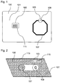
- Fig. 1 shows an identification document 100 that can be realized in the form of a processor card.
- the identification document 100 comprises a carrier material 101, for example made of polycarbonate, and a heat-sensitive layer 103, which is arranged in or on the carrier material 101 and can form a heat-sensitive, optical feature.
- the identification document 100 optionally includes a processor 105.
- the processor 105 stores, for example, electronic data which can be used to identify a person or to check the authenticity of the identification document.
- the processor 105 is integrated, for example, in the carrier material and has the contacts 111, via which the stored data can be read out.
- the heat-sensitive layer 103 is provided to indicate electromagnetic wave manipulation, for example, to destroy the processor 105. However, the processor 105 is not affected by the heat-sensitive layer 103.
- the identification document 100 further comprises an electrically conductive induction structure 107 with a defined heating section 109, which is arranged, for example, at a predetermined location in the carrier material 101.
- the heating portion 109 is provided as a defined heating point in the identification document 101, which heats up when current flows through the heating portion 109 to generate heat to which the heat-sensitive layer 103 responds.
- the heat-sensitive layer 103 may for this purpose have heat-sensitive color pigments whose color changes irreversibly with heat.
- the electrically conductive induction structure 107 is formed as a closed conductor having a cross-section, the taper of which forms the heating section 109.
- the cross section of the trace may be constant outside of the heating section 109.
- the electrically conductive induction structure 107 If electromagnetic waves hit the electrically conductive induction structure 107, a current is induced therein. When the induced current reaches, for example, a certain level, the electrically conductive induction structure 107 heats up at the taper point forming the heating portion 109. The heating can be so strong that the electrically conductive induction structure 107 melts on the heating section 109.
- the heat-sensitive layer 103 is disposed above the heating portion 109, for example, in the form of a color patch according to an embodiment.
- the heating of the heating section 109 is transmitted to the heat-sensitive layer 103 via thermal coupling.
- the heat-sensitive layer 103 is visible at the top of the identification document according to an embodiment 100.
- the cross-sections and the geometry of the electrically conductive induction structure 107 are so dimensioned according to an embodiment that in a normal reading up to 10 times the maximum permissible field strength defined in ISO 14443, a current can flow in the loop without destroying it.
- a current can flow in the loop without destroying it.
- the electrically conductive induction structure 107 melts on the heating section 109, so that a predetermined breaking point can form, since there the electrical resistance is greatest.
- the overlying heat-sensitive layer 103 is also strongly heated.
- the pigmentation of the color of the heat-sensitive layer 103 is selected, for example, such that it changes its spectral response significantly and irreversibly on strong heating, so that a color change becomes visible.
- the temperature may correspond to the temperature which arises in the case of a melt of the heating section 109.
- a white color becomes a green color or a black color becomes a turquoise color.
- the color change is visible on the surface of the identification document 100 and can be optically detected. In this way it can be stated that the identification document has been exposed to a strong electromagnetic field.
- the heat-sensitive layer 103 may have heat-sensitive pigments.
- the pigments used may, for example, be complex salt compounds.
- the pigments of the color may be inorganic color pigments which, upon reaching a certain reversal temperature, have a detectable color change from a first color to a second color.
- the turnover temperature is selected such that, given normal use, the identification document 100 does not undergo color change when used as intended, for example when the identification document 100 is exposed to sunlight.
- a suitable turnover temperature may be, for example, 100 ° C.
- the presence of a color change may indicate that the electronic processor 105 has probably been destroyed.
- the heat-sensitive layer 103 forms an optical feature that is indicative of a tampering attempt.
- the heat-sensitive layer 103 can be tested both manually and by machine. In the case of the presence of the color change can be selectively searched for further manipulation attempts, such as after a photo exchange.
- the electrically conductive induction structure 107 can be formed, for example, by laminar burning of polycarbonate, which can be used as the carrier material 101 for the identification document 100. In the polycarbonate conductive induction structures can be applied, which change irreversibly when introduced into a high-energy electromagnetic field. In an alternative embodiment, the electrically conductive induction structure 107 can be produced by introducing conductive substances, such as conductive silver, as, for example, an electrically conductive trace.
- the induction structure is not limited to any particular embodiment, and any shapes and materials capable of causing heating in the substrate in the presence of increased electromagnetic radiation may be used.
- a conductor track it is also possible, for example, to use a conductive plate as the induction structure in which eddy currents are induced and which thereby heats up.
- FIG. 12 shows a cross-sectional view through the identification document 100 with the heat-sensitive layer 103 for indicating a tampering attempt.
- the identification document 100 has a surface 113 on which the heat-sensitive layer 103 may be disposed.
- the induction structure 107 is arranged circular in cross section in the interior of the carrier material 101 of the identification document 100.
- the heating portion 109 is formed by a tapered portion having a smaller cross section than remaining portions of the induction structure 107, and therefore has a higher resistance.
- the heating portion 109 heats up, so that the thermal energy released thereby is at least partially transmitted to the heat-sensitive layer 103, which may be embodied as a color field pigmented with color pigments 115.
- the color pigments 115 in the heat-sensitive layer are caused, for example, to undergo a thermal reaction by which they change color. This color change can then be recognized from the outside and indicate a manipulation attempt.
- a thermally conductive member such as a metal member may be disposed between the heating portion 109 and the heat-sensitive layer 103 to transmit the thermal energy from the heating portion 109 to the heat-sensitive layer 103.
Landscapes
- Engineering & Computer Science (AREA)
- Computer Hardware Design (AREA)
- Computer Security & Cryptography (AREA)
- General Chemical & Material Sciences (AREA)
- Manufacturing & Machinery (AREA)
- Chemical Kinetics & Catalysis (AREA)
- Chemical & Material Sciences (AREA)
- General Engineering & Computer Science (AREA)
- Microelectronics & Electronic Packaging (AREA)
- Physics & Mathematics (AREA)
- General Physics & Mathematics (AREA)
- Theoretical Computer Science (AREA)
- Credit Cards Or The Like (AREA)
Description
- Die vorliegende Erfindung betrifft ein Identifikationsdokument.
- Die Offenlegungsschrift
DE 196 450 84 A1 zeigt eine Identifikationskarte mit zusätzlichen Sicherheitsmerkmalen und ein Verfahren zu deren Herstellung. - Die Offenlegungsschrift
WO 97/22086 A1 - Die Offenlegungsschrift
FR 2 483 112 - Heutige Identifikationsdokumente sind in der Regel mit einem integrierten Prozessor zur Speicherung des Lichtbildes und biometrischer Merkmale ausgestattet. Nach der derzeitigen deutschen Gesetzlage ist jedoch auch ein Dokument mit zerstörtem oder defektem Prozessor gültig.
- Moderne Identifikationsdokumente verfügen oft über einen integrierten Prozessor, auf welchem neben dem zum biometrisch Vergleich geeigneten Lichtbild oftmals auch weitere biometrische Daten digital signiert gespeichert sind, wie beispielsweise ein Fingerabdruck oder ein Irisbild, sowie eine Textkopie der gedruckten maschinenlesbaren Zone des Ausweisdokumentes.
- Bei der Verifikation des Identifikationsdokumentes, wie beispielsweise an einem Grenzübergang, findet ein Abgleich zwischen dem aufgedruckten Lichtbild und dem auf dem elektronischen Prozessor gespeicherten Lichtbild statt. Auf diese Weise können Manipulationsversuche, wie beispielsweise der Austausch des eingedruckten Lichtbildes erkannt werden. Der weitere Abgleich der optisch personalisierten Daten, wie beispielsweise Name, Geburtsdatum, Seriennummer, Geschlecht oder Ablaufdatum, mit den auf dem Prozessor gespeicherten Daten ermöglicht die Erkennung weiterer Manipulationsversuche.
- Nach der jeweiligen Gesetzeslage behält ein Identifikationsdokument jedoch auch mit zerstörtem oder defektem Prozessor oftmals seine Gültigkeit. Bei manipulierten Dokumenten, wie beispielsweise einem Lichtbildausweis mit zusätzlich elektronisch gespeichertem Lichtbild, wird in der Regel der Prozessor daher zerstört, um so einen elektronischen Abgleich zwischen gespeichertem und gedrucktem Lichtbild zu verhindern. Dies kann beispielsweise dadurch geschehen, dass das Identifikationsdokument mit dem Prozessor energiereichen elektromagnetischen Feldern aussetzt wird, welche den Prozessor zerstören. Ein Beispiel für diesen Fall ist das Einbringen des Identifikationsdokumentes für einige Sekunden in eine Mikrowelle. Von außen ist ein auf diese Weise zerstörtes Identifikationsdokument als solches nicht ohne weiteres erkennbar, sein integrierter Prozessor kann jedoch nicht mehr gelesen werden.
- Die Empfehlungen der Internationalen Zivilluftfahrtorganisation ICAO legen in diesem Fall eine genauere Untersuchung des Dokumentes nahe. Ohne eine teure forensische Untersuchung kann aber nicht festgestellt werden, ob der Prozessor absichtlich oder unbeabsichtigt zerstört worden ist.
- Es ist die Aufgabe der vorliegenden Erfindung, ein Identifikationsdokument bereitzustellen, bei dem ein Manipulationsversuch mittels elektromagnetischer Wellen einfach erkannt werden kann.
- Diese Aufgabe wird durch einen Gegenstand mit den Merkmalen nach dem unabhängigen Anspruch gelöst. Vorteilhafte Weiterbildungen sind Gegenstand der unabhängigen Ansprüche, der Beschreibung und der Zeichnungen.
- Gemäß einem ersten Aspekt wird die erfindungsgemäße Aufgabe durch ein Identifikationsdokument gelöst, mit einem Trägermaterial und einer elektrisch leitenden Induktionsstruktur, welche in dem Trägermaterial angeordnet ist, wobei die elektrisch leitende Induktionsstruktur einen Erwärmungsabschnitt aufweist, welcher durch einen in der elektrisch leitenden Induktionsstruktur induzierbaren elektrischen Strom erwärmbar ist. Der elektrische Strom kann beispielsweise mittels elektromagnetischer Wellen in der elektrisch leitenden Induktionsstruktur induziert werden. Die elektrisch leitende Induktionsstruktur ist somit gemäß einer Ausführungsform eine Empfangsantenne und kann beispielsweise in der Gestalt einer Schleifenantenne geformt sein.
- Gemäß einer Ausführungsform kann die elektrisch leitende Induktionsstruktur eine Antenne bilden oder aufweisen, beispielsweise eine Mehrfach-Antenne. Die Antenne kann derart ausgebildet sein bzw. der Erwärmungsbereich kann derart angeordnet sein, dass die Antenne bei einer Mikrowellenbestrahlung oder einer Strominduktion deformierbar bzw. auflösbar ist.
- Die Induktionsstruktur kann gemäß einer Ausführungsform für eine induktive Kopplung ausgebildet sein. Gemäß einer weiteren Ausführungsform kann die Induktionsstruktur auch für die Übertragung elektromagnetischer Wellen, insbesondere für eine Fernfeldübertragung elektromagnetischer Wellen wie Mikrowellen im Zentimeterbereich, ausgebildet sein. So kann beispielsweise bei einer Einbringung des Identifikationsdokumentes in ein Mikrowellengerät ein Abstand zu beispielsweise einem Magnetron des Mikrowellengerätes von beispielsweise Lambda/6 überschritten werden, so dass in diesem Falle die elektromagnetische Kopplung überwiegen würde.
- Dadurch wird beispielsweise der technische Vorteil erreicht, dass elektromagnetische Wellen, die bei einem Manipulationsversuch verwendet werden, eine durch den induzierten Strom verursachte Veränderung des Dokumentes verursachen. Diese Veränderung kann erfasst werden, so dass ein Manipulationsversuch mittels elektromagnetischer Wellen an der Karte festgestellt werden kann. Dadurch wird ein Indiz erhalten, ob ein elektronischer Prozessor absichtlich oder unabsichtlich zerstört worden ist.
- Ein Identifikationsdokument ist beispielsweise ein Ausweisdokument, ein Reisepass, ein Wertdokument, ein Zahlungsmittel, beispielsweise eine Bankkarte oder eine Kreditkarte, ein Sicherheitsdokument, ein Führerschein, ein Unternehmensausweis, ein Frachtbrief oder ein Berechtigungsausweis. Im Allgemeinen kann ein Identifikationsdokument auch jedes andere Dokument sein, dessen Identität und Echtheit bestätigt werden soll.
- Das Trägermaterial des Identifikationsdokumentes kann ein- oder mehrlagig bzw. papier-und/oder kunststoffbasiert sein. Das Trägermaterial kann aus kunststoffbasierten Folien aufgebaut sein, welche zu einem Kartenkörper mittels Verkleben und/oder Laminieren zusammengefügt werden, wobei die Folien bevorzugt ähnliche stoffliche Eigenschaften aufweisen.
- In einer vorteilhaften Ausführungsform weist der Erwärmungsabschnitt einen höheren elektrischen Widerstand als ein anderer leitfähiger Abschnitt der elektrisch leitenden Induktionsstruktur auf. Dadurch wird beispielsweise der technische Vorteil erreicht, dass sich der Erwärmungsabschnitt auf besonders einfache technische Weise bilden lässt.
- In einer weiteren vorteilhaften Ausführungsform ist der Erwärmungsabschnitt durch eine Verjüngung der elektrisch leitenden Induktionsstruktur gebildet. Dadurch wird beispielsweise der technische Vorteil erreicht, dass sich der Erwärmungsabschnitt auf einfache technische Weise durch eine entsprechende Ausbildung der elektrisch leitenden Induktionsstruktur erzeugen lässt.
- In einer weiteren vorteilhaften Ausführungsform ist der Erwärmungsabschnitt durch einen elektrischen Strom einer vorbestimmten Stromstärke elektrisch durchtrennbar. Dadurch wird beispielsweise der technische Vorteil erreicht, dass ein weiteres unabhängiges Indiz dafür geschaffen wird, dass das Identifikationsdokument einem erhöhten elektrischen Feld ausgesetzt worden ist.
- In einer weiteren vorteilhaften Ausführungsform ist der Erwärmungsabschnitt an einer vorbestimmten Stelle im Trägermaterial angeordnet. Dadurch wird beispielsweise der technische Vorteil erreicht, dass eine Veränderung auf einfache technische Weise an der vorbestimmten Stelle erfasst werden kann.
- In einer weiteren vorteilhaften Ausführungsform weist das Trägermaterial eine wärmeempfindliche Schicht auf, welche durch den Erwärmungsabschnitt erwärmbar ist. Dadurch wird beispielsweise der technische Vorteil erreicht, dass die wärmempfindliche Schicht ein weiteres Merkmal bildet, anhand dessen beurteilt werden kann, ob das Identifikationsdokument einem erhöhten elektrischen Feld ausgesetzt worden ist.
- In einer weiteren vorteilhaften Ausführungsform ist die wärmeempfindliche Schicht oberhalb oder unterhalb des Erwärmungsabschnittes angeordnet. Dadurch wird beispielsweise der technische Vorteil erreicht, dass sich die von dem Erwärmungsabschnitt verursachte Wärmemenge effektiv auf die wärmeempfindliche Schicht überträgt und eine gute thermische Kopplung stattfindet.
- In einer weiteren vorteilhaften Ausführungsform ist eine Farbe der wärmeempfindlichen Schicht bei Erwärmung irreversibel änderbar. Dadurch wird beispielsweise der technische Vorteil erreicht, dass mit einfachen optischen Mitteln oder sogar mit bloßem Auge ein Manipulationsversuch an dem Identifikationsdokument eindeutig erkennbar wird. Dieser Manipulationsversuch kann aufgrund der Irreversibilität des Farbumschlags nicht vertuscht werden.
- In einer weiteren vorteilhaften Ausführungsform umfasst die wärmeempfindliche Schicht wärmeempfindliche Farbpigmente. Dadurch wird beispielsweise der technische Vorteil erreicht, dass die Farbpigmente in einem Anwendungsmedium verwendet werden können. Das Anwendungsmedium bezeichnet dabei einen Stoff, in den das Farbpigment eingearbeitet wird, beispielsweise einen Lack oder einen Kunststoff.
- In einer weiteren vorteilhaften Ausführungsform umfasst die wärmeempfindliche Schicht Farbpigmente, deren spektrale Eigenschaften thermisch irreversibel beeinflussbar sind. Dadurch wird beispielsweise ebenfalls der technische Vorteil erreicht, dass mit einfachen optischen Mitteln oder sogar mit bloßem Auge ein Manipulationsversuch an dem Identifikationsdokument eindeutig erkennbar wird.
- In einer weiteren vorteilhaften Ausführungsform ist die wärmeempfindliche Schicht an einer Oberfläche oder unterhalb einer Oberfläche des Trägermaterials angeordnet. Dadurch wird beispielsweise der technische Vorteil erreicht, dass ein Manipulationsversuch von außen erkennbar wird.
- In einer weiteren vorteilhaften Ausführungsform ist eine Farbe oder eine Farbänderung der wärmeempfindlichen Schicht optisch erfassbar. Dadurch wird beispielsweise der technische Vorteil erreicht, dass eine Änderung der Farbe maschinell ausgewertet werden kann, beispielsweise bei einer Kontrolle des Identifikationsdokumentes.
- In einer weiteren vorteilhaften Ausführungsform ist die elektrisch leitende Induktionsstruktur durch hitzebehandeltes Polycarbonat, durch Graphit oder durch eine metallische Schicht gebildet. Die metallische Schicht kann beispielsweise ein metallisierter Patch sein, welcher in der Gestalt eines Aufklebers auf dem Identifikationsdokument angeordnet ist. Dadurch wird beispielsweise der technische Vorteil erreicht, dass sich die Induktionsstruktur besonders einfach herstellen lässt.
- In einer weiteren vorteilhaften Ausführungsform ist oder umfasst die leitende Induktionsstruktur ferner einen metallischen Faden, der beispielsweise einen sogenannten Holofaden bzw. einen Sicherheitsfaden formt, welcher in dem Identifikationsdokument, beispielsweise in einem Führerschein oder auf einer Banknote angeordnet ist. Dadurch wird beispielsweise der technische Vorteil erreicht, dass sich die Induktionsstruktur besonders einfach herstellen lässt.
- Bei einem Einbringen eines mit einem Sicherheitsfaden bzw. Holofaden versehenen Identifikationsdokumentes, insbesondere eines Wert- und/oder Sicherheitsdokumentes in ein Mikrowellengerät, können sich stehende Wellen in der leitfähigen Induktionsstruktur ausbilden. Der Erwärmungsabschnitt kann daher an einem Bauchbereich der stehenden Welle angeordnet werden, d.h. in einem Bereich, in dem eine Ausbildung einer stehenden Welle zu erwarten ist. Dadurch wird eine besonders effiziente Erfassung eines Nachweises eines Zerstörungsversuchs ermöglicht.
- Gemäß einer Ausführungsform kann sich der Erwärmungsabschnitt über einen Bauch-Knoten-Abschnitt erstrecken. Auf diese Weise kann ein Mikrowelleneinfluss durch benachbarte Bereiche unterschiedlicher Farben angezeigt bzw. erfasst werden.
- Bei einer Frequenz von beispielsweise 2450 MHz sind die Abstände von Wellen-Knoten und -Bäuchen vorhersagbar und betragen beispielsweise 2 cm.
- Der Erwärmungsabschnitt kann gemäß einer Ausführungsform jedoch an einem beliebigen Aufbringungsort mit irreversibler Modifikation bei Erwärmung angeordnet sein.
- In einer weiteren vorteilhaften Ausführungsform läuft die elektrisch leitende Induktionsstruktur an einem Rand des Identifikationsdokumentes um. Die elektrisch leitende Induktionsstruktur verläuft somit entlang des Randes des Identifikationsdokumentes. Dadurch wird beispielsweise der technische Vorteil erreicht, dass die Fläche des Identifikationsdokumentes besonders gut ausgenutzt wird und sich eine hohe Induktion ergibt.
- In einer weiteren vorteilhaften Ausführungsform ist die elektrisch leitende Induktionsstruktur derart frequenzmäßig abgestimmt, dass bei einer Kommunikationsfrequenz aus dem Frequenzbereich zwischen 10 kHz bis 100MHz oder zwischen 100MHZ und 1000 MHZ der Erwärmungsabschnitt nicht erwärmt wird oder geringer erwärmt wird als bei einer Frequenz außerhalb des Frequenzbereichs zwischen 10 kHz bis 100MHz oder zwischen 100MHZ und 1000 MHZ, insbesondere geringer erwärmt wird als bei einer Mikrowellenfrequenz, und/oder dass der Erwärmungsabschnitt bei einer Mikrowellenfrequenz, insbesondere bei 1 GHz +/-100MHZ, erwärmt wird, insbesondere stärker erwärmt wird als bei einer Kommunikationsfrequenz, beispielsweise bei der vorgenannten Kommunikationsfrequenz. Die frequenzmäßige Abstimmung kann beispielsweise durch eine Verstimmung der Resonanzfrequenz erreicht werden. So kann die elektrisch leitende Induktionsstruktur derart angepasst werden, dass deren Resonanzfrequenz außerhalb der Kommunikationsfrequenz liegt. Dadurch wird sichergestellt, dass der Erwärmungsabschnitt bei einer Frequenz im Mikrowellenbereich stärker erwärmt wird als bei einer Frequenz außerhalb des Mikrowellenbereichs.
- Die frequenzmäßige Verstimmung bzw. Einstellung der Resonanzfrequenz kann beispielsweise durch eine geometrische Anpassung der elektrisch leitenden Induktionsstruktur bewirkt werden. Hierzu können zusätzlich passive elektrische Komponenten wie etwa Spule oder Kondensator oder elektrischer Widerstand vorgesehen sein. Grundsätzlich kann die Resonanzfrequenz der elektrisch leitenden Induktionsstruktur wie bei einer elektrischen Empfangsantenne angepasst werden. Die Kommunikationsfrequenz kann grundsätzlich eine derjenigen Frequenzen sein, welche für eine drahtlose Kommunikation geeignet ist.
- In einer weiteren vorteilhaften Ausführungsform umfasst das Trägermaterial Polycarbonat. Dadurch wird beispielsweise der technische Vorteil erreicht, dass ein technisch besonders geeignetes, nicht-leitendes Trägermaterial verwendet wird.
- Weitere Ausführungsbeispiele der Erfindung sind in den Zeichnungen dargestellt und werden im Folgenden näher beschrieben.
- Es zeigen:
- Fig. 1
- eine Aufsicht auf ein Identifikationsdokument; und
- Fig. 2
- eine Querschnittsansicht des Identifikationsdokumentes.
-
Fig. 1 zeigt ein Identifikationsdokument 100, das in der Gestalt einer Prozessorkarte realisiert werden kann. Das Identifikationsdokument 100 umfasst ein Trägermaterial 101, beispielsweise aus Polycarbonat, sowie eine wärmeempfindliche Schicht 103, welche in oder an dem Trägermaterial 101 angeordnet ist und ein wärmeempfindliches, optisches Merkmal bilden kann. - Das Identifikationsdokument 100 umfasst optional einen Prozessor 105. In dem Prozessor 105 sind beispielweise elektronische Daten gespeichert, die zur Identifikation einer Person oder einer Überprüfung der Echtheit des Identifikationsdokumentes herangezogen werden können. Der Prozessor 105 ist beispielsweise in das Trägermaterial integriert und weist die Kontakte 111 auf, über die sich die gespeicherten Daten auslesen lassen. Die wärmeempfindliche Schicht 103 ist vorgesehen, eine Manipulation mittels elektromagnetischer Wellen, um beispielsweise den Prozessor 105 zu zerstören, anzuzeigen. Der Prozessor 105 wird durch die wärmeempfindliche Schicht 103 jedoch nicht beeinflusst.
- Das Identifikationsdokument 100 umfasst ferner eine elektrisch leitende Induktionsstruktur 107 mit einem definierten Erwärmungsabschnitt 109, welcher beispielsweise an einer vorbestimmten Stelle im Trägermaterial 101 angeordnet ist.
- Der Erwärmungsabschnitt 109 ist als definierte Erwärmungsstelle in dem Identifikationsdokument 101 vorgesehen, welche sich bei Stromfluss durch den Erwärmungsabschnitt 109 erwärmt, um Wärme zu erzeugen, auf welche die wärmeempfindliche Schicht 103 reagiert. Die wärmeempfindliche Schicht 103 kann hierzu wärmeempfindliche Farbpigmente aufweisen, deren Farbe sich bei Wärme irreversibel ändert. Dadurch kann ein Manipulationsversuch mittels eines elektromagnetischen Feldes, welches in der Induktionsstruktur 107 einen elektrischen Strom induziert, festgehalten und optisch erkannt werden.
- Gemäß einer Ausführungsform ist die elektrisch leitende Induktionsstruktur 107 als eine geschlossene Leiterbahn mit einem Querschnitt gebildet, dessen Verjüngung den Erwärmungsabschnitt 109 bildet. Der Querschnitt der Leiterbahn kann außerhalb des Erwärmungsabschnitts 109 konstant sein. Dadurch entsteht an dem Erwärmungsabschnitt 109 ein erhöhter elektrischer Widerstand, wodurch sich der Erwärmungsabschnitt 109 stärker erwärmt als andere Abschnitte der elektrisch leitenden Induktionsstruktur 107.
- Treffen elektromagnetische Wellen auf die elektrisch leitende Induktionsstruktur 107, wird darin ein Strom induziert. Erreicht der induzierte Strom beispielsweise eine bestimmte Stärke, erwärmt sich die elektrisch leitende Induktionsstruktur 107 an der Verjüngungsstelle, die den Erwärmungsabschnitt 109 bildet. Die Erwärmung kann dabei so stark sein, dass die elektrisch leitende Induktionsstruktur 107 an dem Erwärmungsabschnitt 109 durchschmilzt.
- Die wärmeempfindliche Schicht 103 ist gemäß einer Ausführungsform über dem Erwärmungsabschnitt 109, beispielsweise in der Gestalt eines Farbfeldes, angeordnet. Die Erwärmung des Erwärmungsabschnitts 109 wird über eine thermische Kopplung an die wärmeempfindliche Schicht 103 übertragen. Die wärmeempfindliche Schicht 103 ist an der Oberseite des Identifikationsdokumentes gemäß einer Ausführungsform 100 sichtbar.
- Die Querschnitte und die Geometrie der elektrisch leitenden Induktionsstruktur 107 sind gemäß einer Ausführungsform so bemessen, dass bei einem normalen Lesevorgang bis zum 10-fachen der nach ISO 14443 festgelegten maximal zulässigen Feldstärke ein Strom in der Schleife fließen kann, ohne diese zu zerstören. Bei größeren Feldstärken, wie beispielsweise in einer Mikrowelle, schmilzt hingegen die elektrisch leitende Induktionsstruktur 107 an dem Erwärmungsabschnitt 109, so dass sich eine Sollbruchstelle bilden kann, da dort der elektrische Widerstand am größten ist. Durch diese induzierte lokale Erwärmung des Erwärmungsabschnitts 109 wird die darüber liegende wärmeempfindliche Schicht 103 ebenfalls stark erwärmt.
- Die Pigmentierung der Farbe der wärmeempfindlichen Schicht 103 ist beispielsweise so gewählt, dass diese bei starker Erwärmung ihre spektrale Reaktion deutlich und irreversibel ändert, so dass ein Farbumschlag sichtbar wird. Die Temperatur kann derjenigen Temperatur entsprechen, welche bei einer Schmelze des Erwärmungsabschnitts 109 entsteht.
- Durch Temperaturveränderung wird so zum Beispiel aus einer weißen Farbe eine grüne Farbe oder aus schwarzer Farbe eine Türkisfarbe. Der Farbumschlag ist an der Oberfläche des Identifikationsdokumentes 100 sichtbar und kann optisch erfasst werden. Auf diese Weise kann festgestellt werden, dass das Identifikationsdokument einem starken elektromagnetischen Feld ausgesetzt worden ist.
- Hierzu kann die wärmeempfindliche Schicht 103 wärmeempfindliche Pigmente aufweisen. Die verwendeten Pigmente können beispielsweise Komplexsalzverbindungen sein. Beispielsweise können die Pigmente der Farbe anorganische Farbpigmente sein, die bei Erreichen einer bestimmten Umschlagstemperatur einen erkennbaren Farbumschlag von einer ersten Farbe in eine zweite Farbe aufweisen. Vorteilhafterweise wird die Umschlagstemperatur so gewählt, dass bei einer normalen Erwärmung des Identifikationsdokumentes 100 bei bestimmungsgemäßem Gebrauch kein Farbumschlag stattfindet, beispielsweise wenn das Identifikationsdokument 100 Sonnenlicht ausgesetzt wird. Eine geeignete Umschlagstemperatur kann beispielsweise bei 100 °C liegen.
- Das Vorliegen eines Farbumschlags kann darauf hindeuten, dass der elektronische Prozessor 105 wahrscheinlich zerstört worden ist. Die wärmeempfindliche Schicht 103 formt gemäß einer Ausführungsform daher ein optisches Merkmal, das ein Indiz für einen Manipulationsversuch darstellt. Die wärmeempfindliche Schicht 103 lässt sich sowohl manuell als auch maschinell prüfen. Im Falle des Vorliegens des Farbumschlags kann selektiv nach weiteren Manipulationsversuchen gesucht werden, wie beispielsweise nach einem Lichtbildaustausch.
- Die elektrisch leitende Induktionsstruktur 107 kann beispielsweise durch flächiges Verbrennen von Polycarbonat gebildet werden, das als Trägermaterial 101 für das Identifikationsdokument 100 eingesetzt werden kann. In dem Polycarbonat können leitende Induktionsstrukturen aufgebracht werden, die sich optisch bei Einbringung in ein energiereiches elektromagnetisches Feld irreversibel verändern. In einer alternativen Ausführungsform kann die elektrisch leitende Induktionsstruktur 107 durch das Einbringen leitfähiger Substanzen, wie beispielsweise Leitsilber, als beispielsweise elektrisch leitende Leiterbahn erzeugt werden.
- Im Allgemeinen ist die Induktionsstruktur nicht auf eine bestimmte Ausführungsform beschränkt und es können alle Formen und Materialien verwendet werden, die geeignet sind, bei Vorliegen erhöhter elektromagnetischer Strahlung eine Erwärmung im Trägermaterial zu bewirken. Statt einer Leiterbahn kann beispielsweise auch eine leitende Platte als Induktionsstruktur verwendet werden, in der Wirbelströme induziert werden und die sich dadurch erwärmt.
-
Fig. 2 zeigt eine Querschnittsansicht durch das Identifikationsdokument 100 mit der wärmeempfindlichen Schicht 103 zur Anzeige eines Manipulationsversuches. Das Identifikationsdokument 100 weist eine Oberfläche 113 auf, auf der die wärmeempfindliche Schicht 103 angeordnet sein kann. - Die Induktionsstruktur 107 ist im Querschnitt kreisförmig im Inneren des Trägermaterials 101 des Identifikationsdokumentes 100 angeordnet. Der Erwärmungsabschnitt 109 ist beispielsweise durch eine Verjüngungsstelle mit geringerem Querschnitt als übrige Abschnitte der Induktionsstruktur 107 gebildet und weist daher einen höheren Widerstand auf.
- Wird ein elektrischer Strom in der Induktionsstruktur 107 induziert, erwärmt sich der Erwärmungsabschnitt 109, so dass die dabei freiwerdende thermische Energie zumindest zum Teil an die wärmeempfindliche Schicht 103, welche als mit Farbpigmenten 115 pigmentiertes Farbfeld ausgeführt sein kann, übertragen wird. Durch die übertragene Energie werden die Farbpigmente 115 in der wärmeempfindlichen Schicht beispielsweise zu einer thermischen Reaktion veranlasst, durch die sie ihre Farbe ändern. Diese Farbänderung kann dann von außen erkannt werden und einen Manipulationsversuch anzeigen.
- In einer anderen Ausführungsform kann zwischen dem Erwärmungsabschnitt 109 und der wärmeempfindlichen Schicht 103 ein thermisch leitendes Element, wie beispielsweise ein Metallelement, angeordnet sein, um die thermische Energie von dem Erwärmungsabschnitt 109 an die wärmeempfindlichen Schicht 103 zu übertragen.
-
- 100
- Identifikationsdokument
- 101
- Trägermaterial
- 103
- wärmeempfindliche Schicht
- 105
- elektronischer Prozessor
- 107
- Induktionsstruktur
- 109
- Erwärmungsabschnitt
- 111
- Kontakte
- 113
- Oberfläche
- 115
- Farbpigmente
Claims (15)
- Identifikationsdokument (100) mit folgenden Merkmalen:einem Trägermaterial (101);einer elektrisch leitenden Induktionsstruktur (107), welche in dem Trägermaterial (101) angeordnet ist, wobei die elektrisch leitende Induktionsstruktur (107) einen Erwärmungsabschnitt (109) aufweist, welcher durch einen in der elektrisch leitenden Induktionsstruktur (107) induzierbaren elektrischen Strom erwärmbar ist.
- Identifikationsdokument (100) nach Anspruch 1, wobei der Erwärmungsabschnitt (109) einen höheren elektrischen Widerstand als ein anderer leitfähiger Abschnitt der elektrisch leitenden Induktionsstruktur (107) aufweist.
- Identifikationsdokument (100) nach Anspruch 1 oder 2, wobei der Erwärmungsabschnitt (109) durch eine Verjüngung der elektrisch leitenden Induktionsstruktur (107) gebildet ist.
- Identifikationsdokument (100) nach einem der vorstehenden Ansprüche, wobei der Erwärmungsabschnitt (109) durch einen elektrischen Strom einer vorbestimmten Stromstärke elektrisch durchtrennbar ist.
- Identifikationsdokument (100) nach einem der vorstehenden Ansprüche, wobei der Erwärmungsabschnitt (109) an einer vorbestimmten Stelle im Trägermaterial (101) angeordnet ist.
- Identifikationsdokument (100) nach einem der vorstehenden Ansprüche, wobei das Trägermaterial (101) eine wärmeempfindliche Schicht (103) aufweist, welche durch den Erwärmungsabschnitt (109) erwärmbar ist.
- Identifikationsdokument (100) nach Anspruch 6, wobei die wärmeempfindliche Schicht (103) oberhalb oder unterhalb des Erwärmungsabschnittes (109) angeordnet ist.
- Identifikationsdokument nach Anspruch 5 oder 6, wobei eine Farbe der wärmeempfindlichen Schicht (103) bei Erwärmung irreversibel änderbar ist.
- Identifikationsdokument (100) nach einem der vorstehenden Ansprüche, wobei die wärmeempfindliche Schicht (103) wärmeempfindliche Farbpigmente (115) umfasst.
- Identifikationsdokument (100) nach einem der vorstehenden Ansprüche, wobei die wärmeempfindliche Schicht (103) Farbpigmente (115) umfasst, deren spektrale Eigenschaften thermisch irreversibel beeinflussbar sind.
- Identifikationsdokument (100) nach einem der vorstehenden Ansprüche, wobei die wärmeempfindliche Schicht (103) an einer Oberfläche (113) oder unterhalb einer Oberfläche (113) des Trägermaterials (101) angeordnet ist.
- Identifikationsdokument (100) nach einem der vorstehenden Ansprüche, wobei eine Farbe oder eine Farbänderung der wärmeempfindlichen Schicht (103) optisch erfassbar ist.
- Identifikationsdokument (100) nach einem der vorstehenden Ansprüche, wobei die elektrisch leitende Induktionsstruktur (107) durch hitzebehandeltes Polycarbonat, durch Graphit oder durch eine metallische Schicht gebildet ist.
- Identifikationsdokument (100) nach einem der vorangehenden Ansprüche, wobei die elektrisch leitende Induktionsstruktur (107) an einem Rand des Identifikationsdokumentes (100) umläuft.
- Identifikationsdokument (100) nach einem der vorangehenden Ansprüche, wobei die elektrisch leitende Induktionsstruktur (107) derart frequenzmäßig abgestimmt ist, dass
bei einer Kommunikationsfrequenz aus dem Frequenzbereich zwischen 10 kHz bis 100MHz oder zwischen 100MHZ und 1000 MHZ der Erwärmungsabschnitt (109) nicht erwärmt wird oder geringer erwärmt wird als bei einer Frequenz außerhalb des Frequenzbereichs zwischen 10 kHz bis 100MHz oder zwischen 100MHZ und 1000 MHZ, insbesondere geringer erwärmt wird als bei einer Mikrowellenfrequenz, oder
der Erwärmungsabschnitt (109) bei einer Mikrowellenfrequenz, insbesondere bei 1 GHz +/-100MHZ erwärmt wird, insbesondere stärker erwärmt wird als bei einer Kommunikationsfrequenz.
Applications Claiming Priority (2)
| Application Number | Priority Date | Filing Date | Title |
|---|---|---|---|
| DE102012211150.6A DE102012211150A1 (de) | 2012-06-28 | 2012-06-28 | Identifikationsdokument |
| PCT/EP2013/062217 WO2014001094A1 (de) | 2012-06-28 | 2013-06-13 | Identifikationsdokument |
Publications (3)
| Publication Number | Publication Date |
|---|---|
| EP2867829A1 EP2867829A1 (de) | 2015-05-06 |
| EP2867829B1 true EP2867829B1 (de) | 2016-08-10 |
| EP2867829B2 EP2867829B2 (de) | 2019-11-20 |
Family
ID=48669908
Family Applications (1)
| Application Number | Title | Priority Date | Filing Date |
|---|---|---|---|
| EP13730179.2A Active EP2867829B2 (de) | 2012-06-28 | 2013-06-13 | Identifikationsdokument |
Country Status (3)
| Country | Link |
|---|---|
| EP (1) | EP2867829B2 (de) |
| DE (1) | DE102012211150A1 (de) |
| WO (1) | WO2014001094A1 (de) |
Families Citing this family (5)
| Publication number | Priority date | Publication date | Assignee | Title |
|---|---|---|---|---|
| DE102015106358B4 (de) | 2015-04-24 | 2020-07-09 | Bundesdruckerei Gmbh | Bilderfassungsvorrichtung zur Aufnahme von Bildern für die Personenidentifikation |
| DE102015117634A1 (de) * | 2015-10-16 | 2017-04-20 | Bundesdruckerei Gmbh | Berechtigungstoken, elektronisches Identifikationsdokument und elektronisches Berechtigungskontrollsystem |
| DE102016113656A1 (de) * | 2016-07-25 | 2018-01-25 | Infineon Technologies Ag | Elektronisches identifikationsdokument |
| DE102017012283B3 (de) | 2017-05-29 | 2022-02-10 | Infineon Technologies Ag | Elektronisches Identifikationsdokument |
| DE102017111639B4 (de) | 2017-05-29 | 2019-08-08 | Infineon Technologies Ag | Elektronisches Identifikationsdokument und Verfahren zur Herstellung eines elektronischen Identifikationsdokuments |
Citations (6)
| Publication number | Priority date | Publication date | Assignee | Title |
|---|---|---|---|---|
| FR2483112A1 (fr) | 1980-05-21 | 1981-11-27 | Crouzet Sa | Element de memoire magnetique thermo-inutilisable |
| DE4221305A1 (de) | 1992-05-20 | 1993-11-25 | Neutron Electronic Computer Ge | Kartenförmiger Informationsgeber und dessen Verwendung |
| WO1997022086A1 (de) | 1995-12-14 | 1997-06-19 | Landis & Gyr Technology Innovation Ag | Zusatzsicherheitsmerkmal für chipkarten |
| DE19645084A1 (de) | 1996-11-01 | 1998-05-07 | Austria Card Gmbh | Identifikationskarte mit zusätzlichen Sicherheitsmerkmalen und Verfahren zu deren Herstellung |
| WO2002025600A2 (de) | 2000-09-21 | 2002-03-28 | Bundesdruckerei Gmbh | Fälschungs- und diebstahlsicherungssystem insbesondere für wert- und sicherheitsdokumente |
| DE102008011299A1 (de) | 2008-02-27 | 2009-09-03 | Giesecke & Devrient Gmbh | Wertdokument mit Fälschungssicherung durch thermochrome Anzeige. |
Family Cites Families (2)
| Publication number | Priority date | Publication date | Assignee | Title |
|---|---|---|---|---|
| JP3418322B2 (ja) * | 1997-08-28 | 2003-06-23 | 日本電信電話株式会社 | 使用状態表示機能付きicカードおよびicカードシステム |
| DE102010034156A1 (de) * | 2010-08-11 | 2012-02-16 | Ovd Kinegram Ag | Folienelement |
-
2012
- 2012-06-28 DE DE102012211150.6A patent/DE102012211150A1/de not_active Withdrawn
-
2013
- 2013-06-13 WO PCT/EP2013/062217 patent/WO2014001094A1/de not_active Ceased
- 2013-06-13 EP EP13730179.2A patent/EP2867829B2/de active Active
Patent Citations (6)
| Publication number | Priority date | Publication date | Assignee | Title |
|---|---|---|---|---|
| FR2483112A1 (fr) | 1980-05-21 | 1981-11-27 | Crouzet Sa | Element de memoire magnetique thermo-inutilisable |
| DE4221305A1 (de) | 1992-05-20 | 1993-11-25 | Neutron Electronic Computer Ge | Kartenförmiger Informationsgeber und dessen Verwendung |
| WO1997022086A1 (de) | 1995-12-14 | 1997-06-19 | Landis & Gyr Technology Innovation Ag | Zusatzsicherheitsmerkmal für chipkarten |
| DE19645084A1 (de) | 1996-11-01 | 1998-05-07 | Austria Card Gmbh | Identifikationskarte mit zusätzlichen Sicherheitsmerkmalen und Verfahren zu deren Herstellung |
| WO2002025600A2 (de) | 2000-09-21 | 2002-03-28 | Bundesdruckerei Gmbh | Fälschungs- und diebstahlsicherungssystem insbesondere für wert- und sicherheitsdokumente |
| DE102008011299A1 (de) | 2008-02-27 | 2009-09-03 | Giesecke & Devrient Gmbh | Wertdokument mit Fälschungssicherung durch thermochrome Anzeige. |
Also Published As
| Publication number | Publication date |
|---|---|
| DE102012211150A1 (de) | 2014-01-02 |
| EP2867829A1 (de) | 2015-05-06 |
| WO2014001094A1 (de) | 2014-01-03 |
| EP2867829B2 (de) | 2019-11-20 |
Similar Documents
| Publication | Publication Date | Title |
|---|---|---|
| EP2867829B1 (de) | Identifikationsdokument | |
| EP1501054B1 (de) | Verfahren zur Prüfung der Echtheit von Urkunden | |
| EP2248111B1 (de) | Wertdokument mit fälschungssicherung durch thermochrome anzeige | |
| DE102009023715A1 (de) | Sicherheitsdokument | |
| EP2050045B1 (de) | Sicherheitselemente für antennen | |
| EP1463637B1 (de) | Wert- oder sicherheitsdokument mit einem schalter | |
| WO2019185192A1 (de) | Fahrzeugidentifikationsmittel | |
| DE102013103856B4 (de) | Gesichertes EPass-Heft basierend auf einer zweifach Chip-Technologie | |
| DE19833746A1 (de) | Sicherheitspapier und Verfahren zur Prüfung der Echtheit darauf aufgezeichneter Urkunden | |
| DE102016113656A1 (de) | Elektronisches identifikationsdokument | |
| AT504243B1 (de) | Verfahren zur herstellung eines identifikationsträgers oder elektronischen schlüssels für elektronisch betätigbare schlösser | |
| DE112008003875T5 (de) | Multimodale Sicherheitsabschreckungen und Verfahren zum Herstellen derselben | |
| DE102004043064A1 (de) | Sicherheitselement mit maschinenlesbarem Echtheitsmerkmal | |
| DE2553811C3 (de) | Maschinell lesbarer Datenträger und Vorrichtung zum Prüfen desselben | |
| EP1969533A1 (de) | Dokument mit einem datenspeicher, vorrichtung und verfahren zum lesen eines funketiketts und computerprogrammprodukt | |
| EP2838055A2 (de) | Dokument mit einer integrierten Anzeigevorrichtung, Verfahren zur Herstellung eines Dokuments und Lesegerät | |
| DE102007037293A1 (de) | Vorrichtung, Verfahren und Verwendung zur Magnetfeldabschirmung eines RFID-Transponders | |
| DE102017111639B4 (de) | Elektronisches Identifikationsdokument und Verfahren zur Herstellung eines elektronischen Identifikationsdokuments | |
| DE202005013346U1 (de) | Ausweis-Schutzhülle | |
| DE102010054053A1 (de) | Datenträger, Sicherheitselement und Verfahren zum Beeinflussen des Farbwechsels thermochromer Farbschichten | |
| DE202007007418U1 (de) | Sicherheitseinrichtung für mit RFIDs versehene Reisepässe | |
| DE102007008151A1 (de) | Sicherheitsmerkmal für die Echtheit eines Dokuments und Verfahren zur Prüfung seiner Echtheit | |
| DE69733615T2 (de) | Verfahren zur fertigung eines funkziels | |
| WO2015086712A1 (de) | Sicherheitsdokument mit prüfeinrichtung für eine schaltung und verfahren zum prüfen einer schaltung in einem sicherheitsdokument | |
| DE102017012284B3 (de) | Elektronisches Identifikationsdokument |
Legal Events
| Date | Code | Title | Description |
|---|---|---|---|
| PUAI | Public reference made under article 153(3) epc to a published international application that has entered the european phase |
Free format text: ORIGINAL CODE: 0009012 |
|
| 17P | Request for examination filed |
Effective date: 20141125 |
|
| AK | Designated contracting states |
Kind code of ref document: A1 Designated state(s): AL AT BE BG CH CY CZ DE DK EE ES FI FR GB GR HR HU IE IS IT LI LT LU LV MC MK MT NL NO PL PT RO RS SE SI SK SM TR |
|
| AX | Request for extension of the european patent |
Extension state: BA ME |
|
| DAX | Request for extension of the european patent (deleted) | ||
| GRAP | Despatch of communication of intention to grant a patent |
Free format text: ORIGINAL CODE: EPIDOSNIGR1 |
|
| RIC1 | Information provided on ipc code assigned before grant |
Ipc: G06K 19/073 20060101AFI20160218BHEP Ipc: G06K 17/00 20060101ALI20160218BHEP Ipc: B42D 25/29 20140101ALI20160218BHEP Ipc: B42D 25/00 20140101ALI20160218BHEP |
|
| INTG | Intention to grant announced |
Effective date: 20160316 |
|
| GRAS | Grant fee paid |
Free format text: ORIGINAL CODE: EPIDOSNIGR3 |
|
| RIN1 | Information on inventor provided before grant (corrected) |
Inventor name: WOLF, ANDREAS, DR. Inventor name: SCHUERING, ANDREAS Inventor name: RABELER, UWE |
|
| RAP1 | Party data changed (applicant data changed or rights of an application transferred) |
Owner name: BUNDESDRUCKEREI GMBH |
|
| GRAA | (expected) grant |
Free format text: ORIGINAL CODE: 0009210 |
|
| AK | Designated contracting states |
Kind code of ref document: B1 Designated state(s): AL AT BE BG CH CY CZ DE DK EE ES FI FR GB GR HR HU IE IS IT LI LT LU LV MC MK MT NL NO PL PT RO RS SE SI SK SM TR |
|
| REG | Reference to a national code |
Ref country code: GB Ref legal event code: FG4D Free format text: NOT ENGLISH |
|
| REG | Reference to a national code |
Ref country code: CH Ref legal event code: EP Ref country code: AT Ref legal event code: REF Ref document number: 819631 Country of ref document: AT Kind code of ref document: T Effective date: 20160815 |
|
| REG | Reference to a national code |
Ref country code: IE Ref legal event code: FG4D Free format text: LANGUAGE OF EP DOCUMENT: GERMAN |
|
| REG | Reference to a national code |
Ref country code: DE Ref legal event code: R096 Ref document number: 502013004060 Country of ref document: DE |
|
| REG | Reference to a national code |
Ref country code: NL Ref legal event code: FP |
|
| REG | Reference to a national code |
Ref country code: LT Ref legal event code: MG4D |
|
| PG25 | Lapsed in a contracting state [announced via postgrant information from national office to epo] |
Ref country code: IT Free format text: LAPSE BECAUSE OF FAILURE TO SUBMIT A TRANSLATION OF THE DESCRIPTION OR TO PAY THE FEE WITHIN THE PRESCRIBED TIME-LIMIT Effective date: 20160810 Ref country code: NO Free format text: LAPSE BECAUSE OF FAILURE TO SUBMIT A TRANSLATION OF THE DESCRIPTION OR TO PAY THE FEE WITHIN THE PRESCRIBED TIME-LIMIT Effective date: 20161110 Ref country code: IS Free format text: LAPSE BECAUSE OF FAILURE TO SUBMIT A TRANSLATION OF THE DESCRIPTION OR TO PAY THE FEE WITHIN THE PRESCRIBED TIME-LIMIT Effective date: 20161210 Ref country code: HR Free format text: LAPSE BECAUSE OF FAILURE TO SUBMIT A TRANSLATION OF THE DESCRIPTION OR TO PAY THE FEE WITHIN THE PRESCRIBED TIME-LIMIT Effective date: 20160810 Ref country code: RS Free format text: LAPSE BECAUSE OF FAILURE TO SUBMIT A TRANSLATION OF THE DESCRIPTION OR TO PAY THE FEE WITHIN THE PRESCRIBED TIME-LIMIT Effective date: 20160810 Ref country code: FI Free format text: LAPSE BECAUSE OF FAILURE TO SUBMIT A TRANSLATION OF THE DESCRIPTION OR TO PAY THE FEE WITHIN THE PRESCRIBED TIME-LIMIT Effective date: 20160810 Ref country code: LT Free format text: LAPSE BECAUSE OF FAILURE TO SUBMIT A TRANSLATION OF THE DESCRIPTION OR TO PAY THE FEE WITHIN THE PRESCRIBED TIME-LIMIT Effective date: 20160810 |
|
| PG25 | Lapsed in a contracting state [announced via postgrant information from national office to epo] |
Ref country code: PL Free format text: LAPSE BECAUSE OF FAILURE TO SUBMIT A TRANSLATION OF THE DESCRIPTION OR TO PAY THE FEE WITHIN THE PRESCRIBED TIME-LIMIT Effective date: 20160810 Ref country code: LV Free format text: LAPSE BECAUSE OF FAILURE TO SUBMIT A TRANSLATION OF THE DESCRIPTION OR TO PAY THE FEE WITHIN THE PRESCRIBED TIME-LIMIT Effective date: 20160810 Ref country code: SE Free format text: LAPSE BECAUSE OF FAILURE TO SUBMIT A TRANSLATION OF THE DESCRIPTION OR TO PAY THE FEE WITHIN THE PRESCRIBED TIME-LIMIT Effective date: 20160810 Ref country code: PT Free format text: LAPSE BECAUSE OF FAILURE TO SUBMIT A TRANSLATION OF THE DESCRIPTION OR TO PAY THE FEE WITHIN THE PRESCRIBED TIME-LIMIT Effective date: 20161212 Ref country code: ES Free format text: LAPSE BECAUSE OF FAILURE TO SUBMIT A TRANSLATION OF THE DESCRIPTION OR TO PAY THE FEE WITHIN THE PRESCRIBED TIME-LIMIT Effective date: 20160810 Ref country code: GR Free format text: LAPSE BECAUSE OF FAILURE TO SUBMIT A TRANSLATION OF THE DESCRIPTION OR TO PAY THE FEE WITHIN THE PRESCRIBED TIME-LIMIT Effective date: 20161111 |
|
| PG25 | Lapsed in a contracting state [announced via postgrant information from national office to epo] |
Ref country code: RO Free format text: LAPSE BECAUSE OF FAILURE TO SUBMIT A TRANSLATION OF THE DESCRIPTION OR TO PAY THE FEE WITHIN THE PRESCRIBED TIME-LIMIT Effective date: 20160810 Ref country code: EE Free format text: LAPSE BECAUSE OF FAILURE TO SUBMIT A TRANSLATION OF THE DESCRIPTION OR TO PAY THE FEE WITHIN THE PRESCRIBED TIME-LIMIT Effective date: 20160810 |
|
| REG | Reference to a national code |
Ref country code: DE Ref legal event code: R026 Ref document number: 502013004060 Country of ref document: DE |
|
| PLBI | Opposition filed |
Free format text: ORIGINAL CODE: 0009260 |
|
| PG25 | Lapsed in a contracting state [announced via postgrant information from national office to epo] |
Ref country code: BG Free format text: LAPSE BECAUSE OF FAILURE TO SUBMIT A TRANSLATION OF THE DESCRIPTION OR TO PAY THE FEE WITHIN THE PRESCRIBED TIME-LIMIT Effective date: 20161110 Ref country code: SM Free format text: LAPSE BECAUSE OF FAILURE TO SUBMIT A TRANSLATION OF THE DESCRIPTION OR TO PAY THE FEE WITHIN THE PRESCRIBED TIME-LIMIT Effective date: 20160810 Ref country code: CZ Free format text: LAPSE BECAUSE OF FAILURE TO SUBMIT A TRANSLATION OF THE DESCRIPTION OR TO PAY THE FEE WITHIN THE PRESCRIBED TIME-LIMIT Effective date: 20160810 Ref country code: SK Free format text: LAPSE BECAUSE OF FAILURE TO SUBMIT A TRANSLATION OF THE DESCRIPTION OR TO PAY THE FEE WITHIN THE PRESCRIBED TIME-LIMIT Effective date: 20160810 Ref country code: DK Free format text: LAPSE BECAUSE OF FAILURE TO SUBMIT A TRANSLATION OF THE DESCRIPTION OR TO PAY THE FEE WITHIN THE PRESCRIBED TIME-LIMIT Effective date: 20160810 |
|
| PLAX | Notice of opposition and request to file observation + time limit sent |
Free format text: ORIGINAL CODE: EPIDOSNOBS2 |
|
| 26 | Opposition filed |
Opponent name: GIESECKE & DEVRIENT GMBH Effective date: 20170510 |
|
| REG | Reference to a national code |
Ref country code: FR Ref legal event code: PLFP Year of fee payment: 5 |
|
| PG25 | Lapsed in a contracting state [announced via postgrant information from national office to epo] |
Ref country code: SI Free format text: LAPSE BECAUSE OF FAILURE TO SUBMIT A TRANSLATION OF THE DESCRIPTION OR TO PAY THE FEE WITHIN THE PRESCRIBED TIME-LIMIT Effective date: 20160810 |
|
| PLBB | Reply of patent proprietor to notice(s) of opposition received |
Free format text: ORIGINAL CODE: EPIDOSNOBS3 |
|
| PG25 | Lapsed in a contracting state [announced via postgrant information from national office to epo] |
Ref country code: MC Free format text: LAPSE BECAUSE OF FAILURE TO SUBMIT A TRANSLATION OF THE DESCRIPTION OR TO PAY THE FEE WITHIN THE PRESCRIBED TIME-LIMIT Effective date: 20160810 |
|
| REG | Reference to a national code |
Ref country code: CH Ref legal event code: PL |
|
| REG | Reference to a national code |
Ref country code: IE Ref legal event code: MM4A |
|
| PG25 | Lapsed in a contracting state [announced via postgrant information from national office to epo] |
Ref country code: LU Free format text: LAPSE BECAUSE OF NON-PAYMENT OF DUE FEES Effective date: 20170613 Ref country code: LI Free format text: LAPSE BECAUSE OF NON-PAYMENT OF DUE FEES Effective date: 20170630 Ref country code: IE Free format text: LAPSE BECAUSE OF NON-PAYMENT OF DUE FEES Effective date: 20170613 Ref country code: CH Free format text: LAPSE BECAUSE OF NON-PAYMENT OF DUE FEES Effective date: 20170630 |
|
| REG | Reference to a national code |
Ref country code: BE Ref legal event code: MM Effective date: 20170630 |
|
| REG | Reference to a national code |
Ref country code: FR Ref legal event code: PLFP Year of fee payment: 6 |
|
| PG25 | Lapsed in a contracting state [announced via postgrant information from national office to epo] |
Ref country code: BE Free format text: LAPSE BECAUSE OF NON-PAYMENT OF DUE FEES Effective date: 20170630 |
|
| PG25 | Lapsed in a contracting state [announced via postgrant information from national office to epo] |
Ref country code: MT Free format text: LAPSE BECAUSE OF FAILURE TO SUBMIT A TRANSLATION OF THE DESCRIPTION OR TO PAY THE FEE WITHIN THE PRESCRIBED TIME-LIMIT Effective date: 20160810 |
|
| PLAB | Opposition data, opponent's data or that of the opponent's representative modified |
Free format text: ORIGINAL CODE: 0009299OPPO |
|
| PG25 | Lapsed in a contracting state [announced via postgrant information from national office to epo] |
Ref country code: AL Free format text: LAPSE BECAUSE OF FAILURE TO SUBMIT A TRANSLATION OF THE DESCRIPTION OR TO PAY THE FEE WITHIN THE PRESCRIBED TIME-LIMIT Effective date: 20160810 |
|
| R26 | Opposition filed (corrected) |
Opponent name: GIESECKE & DEVRIENT GMBH Effective date: 20170510 |
|
| RIC2 | Information provided on ipc code assigned after grant |
Ipc: B42D 25/373 20140101ALI20190128BHEP Ipc: B42D 25/305 20140101AFI20190128BHEP Ipc: B42D 25/378 20140101ALI20190128BHEP Ipc: G06K 19/073 20060101ALI20190128BHEP Ipc: G06K 17/00 20060101ALI20190128BHEP |
|
| PLAB | Opposition data, opponent's data or that of the opponent's representative modified |
Free format text: ORIGINAL CODE: 0009299OPPO |
|
| R26 | Opposition filed (corrected) |
Opponent name: GIESECKE & DEVRIENT GMBH Effective date: 20170510 |
|
| PG25 | Lapsed in a contracting state [announced via postgrant information from national office to epo] |
Ref country code: HU Free format text: LAPSE BECAUSE OF FAILURE TO SUBMIT A TRANSLATION OF THE DESCRIPTION OR TO PAY THE FEE WITHIN THE PRESCRIBED TIME-LIMIT; INVALID AB INITIO Effective date: 20130613 |
|
| RIN2 | Information on inventor provided after grant (corrected) |
Inventor name: RABELER, UWE Inventor name: SCHUERING, ANDREAS Inventor name: WOLF, ANDREAS |
|
| REG | Reference to a national code |
Ref country code: AT Ref legal event code: MM01 Ref document number: 819631 Country of ref document: AT Kind code of ref document: T Effective date: 20180613 |
|
| PUAH | Patent maintained in amended form |
Free format text: ORIGINAL CODE: 0009272 |
|
| STAA | Information on the status of an ep patent application or granted ep patent |
Free format text: STATUS: PATENT MAINTAINED AS AMENDED |
|
| PG25 | Lapsed in a contracting state [announced via postgrant information from national office to epo] |
Ref country code: CY Free format text: LAPSE BECAUSE OF FAILURE TO SUBMIT A TRANSLATION OF THE DESCRIPTION OR TO PAY THE FEE WITHIN THE PRESCRIBED TIME-LIMIT Effective date: 20160810 |
|
| 27A | Patent maintained in amended form |
Effective date: 20191120 |
|
| AK | Designated contracting states |
Kind code of ref document: B2 Designated state(s): AL AT BE BG CH CY CZ DE DK EE ES FI FR GB GR HR HU IE IS IT LI LT LU LV MC MK MT NL NO PL PT RO RS SE SI SK SM TR |
|
| REG | Reference to a national code |
Ref country code: DE Ref legal event code: R102 Ref document number: 502013004060 Country of ref document: DE |
|
| PG25 | Lapsed in a contracting state [announced via postgrant information from national office to epo] |
Ref country code: MK Free format text: LAPSE BECAUSE OF FAILURE TO SUBMIT A TRANSLATION OF THE DESCRIPTION OR TO PAY THE FEE WITHIN THE PRESCRIBED TIME-LIMIT Effective date: 20160810 |
|
| PG25 | Lapsed in a contracting state [announced via postgrant information from national office to epo] |
Ref country code: AT Free format text: LAPSE BECAUSE OF NON-PAYMENT OF DUE FEES Effective date: 20180613 |
|
| REG | Reference to a national code |
Ref country code: NL Ref legal event code: FP |
|
| PG25 | Lapsed in a contracting state [announced via postgrant information from national office to epo] |
Ref country code: TR Free format text: LAPSE BECAUSE OF FAILURE TO SUBMIT A TRANSLATION OF THE DESCRIPTION OR TO PAY THE FEE WITHIN THE PRESCRIBED TIME-LIMIT Effective date: 20160810 |
|
| P01 | Opt-out of the competence of the unified patent court (upc) registered |
Effective date: 20230526 |
|
| PGFP | Annual fee paid to national office [announced via postgrant information from national office to epo] |
Ref country code: DE Payment date: 20250618 Year of fee payment: 13 |
|
| PGFP | Annual fee paid to national office [announced via postgrant information from national office to epo] |
Ref country code: GB Payment date: 20250620 Year of fee payment: 13 |
|
| PGFP | Annual fee paid to national office [announced via postgrant information from national office to epo] |
Ref country code: NL Payment date: 20250618 Year of fee payment: 13 |
|
| PGFP | Annual fee paid to national office [announced via postgrant information from national office to epo] |
Ref country code: FR Payment date: 20250618 Year of fee payment: 13 |