EP2867635B1 - Hybrider lastdifferenzverstärker betriebsfähig in einer hochtemperaturumgebung eines turbinenmotors - Google Patents
Hybrider lastdifferenzverstärker betriebsfähig in einer hochtemperaturumgebung eines turbinenmotors Download PDFInfo
- Publication number
- EP2867635B1 EP2867635B1 EP13731195.7A EP13731195A EP2867635B1 EP 2867635 B1 EP2867635 B1 EP 2867635B1 EP 13731195 A EP13731195 A EP 13731195A EP 2867635 B1 EP2867635 B1 EP 2867635B1
- Authority
- EP
- European Patent Office
- Prior art keywords
- circuitry
- semiconductor switches
- pair
- switches
- differential amplifier
- Prior art date
- Legal status (The legal status is an assumption and is not a legal conclusion. Google has not performed a legal analysis and makes no representation as to the accuracy of the status listed.)
- Not-in-force
Links
Images
Classifications
-
- H—ELECTRICITY
- H03—ELECTRONIC CIRCUITRY
- H03F—AMPLIFIERS
- H03F3/00—Amplifiers with only discharge tubes or only semiconductor devices as amplifying elements
- H03F3/45—Differential amplifiers
-
- F—MECHANICAL ENGINEERING; LIGHTING; HEATING; WEAPONS; BLASTING
- F01—MACHINES OR ENGINES IN GENERAL; ENGINE PLANTS IN GENERAL; STEAM ENGINES
- F01D—NON-POSITIVE DISPLACEMENT MACHINES OR ENGINES, e.g. STEAM TURBINES
- F01D17/00—Regulating or controlling by varying flow
- F01D17/02—Arrangement of sensing elements
- F01D17/08—Arrangement of sensing elements responsive to condition of working-fluid, e.g. pressure
- F01D17/085—Arrangement of sensing elements responsive to condition of working-fluid, e.g. pressure to temperature
-
- F—MECHANICAL ENGINEERING; LIGHTING; HEATING; WEAPONS; BLASTING
- F01—MACHINES OR ENGINES IN GENERAL; ENGINE PLANTS IN GENERAL; STEAM ENGINES
- F01D—NON-POSITIVE DISPLACEMENT MACHINES OR ENGINES, e.g. STEAM TURBINES
- F01D5/00—Blades; Blade-carrying members; Heating, heat-insulating, cooling or antivibration means on the blades or the members
- F01D5/12—Blades
- F01D5/14—Form or construction
-
- F—MECHANICAL ENGINEERING; LIGHTING; HEATING; WEAPONS; BLASTING
- F01—MACHINES OR ENGINES IN GENERAL; ENGINE PLANTS IN GENERAL; STEAM ENGINES
- F01D—NON-POSITIVE DISPLACEMENT MACHINES OR ENGINES, e.g. STEAM TURBINES
- F01D5/00—Blades; Blade-carrying members; Heating, heat-insulating, cooling or antivibration means on the blades or the members
- F01D5/30—Fixing blades to rotors; Blade roots ; Blade spacers
- F01D5/3007—Fixing blades to rotors; Blade roots ; Blade spacers of axial insertion type
-
- G—PHYSICS
- G01—MEASURING; TESTING
- G01L—MEASURING FORCE, STRESS, TORQUE, WORK, MECHANICAL POWER, MECHANICAL EFFICIENCY, OR FLUID PRESSURE
- G01L1/00—Measuring force or stress, in general
- G01L1/20—Measuring force or stress, in general by measuring variations in ohmic resistance of solid materials or of electrically-conductive fluids; by making use of electrokinetic cells, i.e. liquid-containing cells wherein an electrical potential is produced or varied upon the application of stress
- G01L1/22—Measuring force or stress, in general by measuring variations in ohmic resistance of solid materials or of electrically-conductive fluids; by making use of electrokinetic cells, i.e. liquid-containing cells wherein an electrical potential is produced or varied upon the application of stress using resistance strain gauges
- G01L1/225—Measuring circuits therefor
-
- F—MECHANICAL ENGINEERING; LIGHTING; HEATING; WEAPONS; BLASTING
- F05—INDEXING SCHEMES RELATING TO ENGINES OR PUMPS IN VARIOUS SUBCLASSES OF CLASSES F01-F04
- F05D—INDEXING SCHEME FOR ASPECTS RELATING TO NON-POSITIVE-DISPLACEMENT MACHINES OR ENGINES, GAS-TURBINES OR JET-PROPULSION PLANTS
- F05D2270/00—Control
- F05D2270/50—Control logic embodiments
- F05D2270/54—Control logic embodiments by electronic means, e.g. electronic tubes, transistors or IC's within an electronic circuit
Definitions
- the present invention relates to circuitry adapted to operate in an environment of a turbine engine having a maximum operating temperature exceeding 300 °C.
- Turbine engines such as gas turbine engines, may be used in a variety of applications, such as driving an electric generator in a power generating plant or propelling a ship or an aircraft. Firing temperatures of modern gas turbine engines continue to increase in response to the demand for higher combustion efficiency.
- circuitry such as may be used in a wireless telemetry system, to monitor operational parameters of the engine. For example, to monitor operating temperatures of components of the turbine, such as a turbine blade, or to monitor operational stresses placed upon such components during operation of the engine. Aspects of the present invention offer improvements in connection with such a circuitry.
- WO 2010/019404 A2 discloses a telemetry system for use in an engine.
- the telemetry system includes a circuit structure affixed to a moving part of the engine and disposed for amplifying information sensed about a condition of the part and transmitting the sensed information to a receiver external to the engine.
- the circuit structure is adapted for the high temperature environment of the engine and includes a differential amplifier having an input for receiving a signal from a sensor disposed on the moving part.
- a voltage controlled oscillator with an input coupled to the output of the amplifier produces an oscillatory signal having a frequency representative of the sensed condition.
- a buffer with an input coupled to the output of the oscillator buffers the oscillatory signal, which is then coupled to an antenna for transmitting the information to the receiver.
- Described below is electronic circuitry, which, in one example application, may be used in a turbine engine instrumented with a telemetry system.
- This example application may allow transmitting sensor data from a movable component, such as a rotatable turbine engine blade, having certain electronic circuitry, which is able to operate in an environment having a temperature exceeding 300 °C.
- the term "high temperature" environment without additional qualification refers to any operating environment within a turbine engine having a maximum operating temperature exceeding 300 °C. It will be appreciated that the present invention is not limited to use in a high temperature environment, since the present invention may be used equally effectively in a non-high temperature environment.
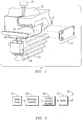
- FIG. 1 illustrates a turbine blade 20 (fragmentarily illustrated), as may be instrumented with an example telemetry system, which may include a wireless telemetry transmitter assembly 24 and an antenna assembly 26.
- Lead lines or connectors 28 may extend from one or more sensors, such as sensor 30, to telemetry transmitter assembly 24, which may be mounted proximate a blade root 22 and may include various telemetry transmitter circuitry.
- Lead lines 28 may route electronic data signals from sensor 30 to telemetry transmitter assembly 24, where the signals may be processed by a processor.
- Further lead lines or electrical connectors 36 may be used for routing electronic data signals from telemetry transmitter circuitry to antenna assembly 26.
- FIG. 2 illustrates a block diagram of an example strain gauge circuitry, which may be used in a turbine component (e.g., turbine blade 20 ( FIG. 1 )) instrumented with a telemetry system.
- a signal indicative of the amount of strain, which may develop on a measured turbine component may be sensed by a strain gauge 101, which signal may be coupled to a differential amplifier 102.
- the output of the differential amplifier 102 may be coupled to a voltage-controlled oscillator (VC0) 104, which may generate an oscillatory signal having a frequency, which is indicative of the amount of strain which develops on the measured turbine component.
- This oscillatory signal may be buffered by a buffer 105 and coupled to antenna 26 for transmission to an external receiver (not shown), which may be tuned to the carrier frequency.
- FIGs. 3-4 and related description below will provide details of circuitry in accordance with the present invention, which in one example application, may be used in strain gauge circuitry, as exemplarily illustrated in FIG. 2 . It will be appreciated that such example application should not be construed in a limiting sense being that circuitry in accordance with the present invention may be used in other applications.
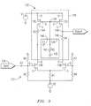
- FIG. 3 is a schematic representation of one example circuitry 120 (also shown in FIG. 4 ) in accordance with the present invention.
- Circuitry 120 includes a differential amplifier 122 having an input terminal 124, which is coupled to a sensing element (e.g., strain gauge 101 FIG. 2 ) to receive the voltage indicative of a sensed parameter (e.g., voltage indicative of strain).
- Differential amplifier 122 includes a first pair of semiconductor switches 126, 128 (e.g., differential pair of semiconductor switches). Biasing of the differential pair of semiconductor switches 126, 128 may be controlled by a bridge circuit made up by resistors R5, R6, R7 and R8 using biasing techniques well-understood by one skilled in the art.
- Circuitry 120 further includes a hybrid load circuitry 125, which in accordance with the present invention is AC-coupled (alternating current-coupled) to differential amplifier 122, as elaborated in greater detail below.
- Hybrid load circuitry 125 includes a second pair of semiconductor switches 130,132 (e.g., active-load pair of semiconductor switches). Each of such pairs of semiconductor switches has a respective drain terminal (D), a respective source terminal (S) and a respective gating terminal (G).
- the first pair of semiconductor switches 126, 128 and the second pair of semiconductor switches 130, 132 involve circuitry without complementary pairs of semiconductor switches.
- the first pair of semiconductor switches 126, 128 and the second pair of semiconductor switches 130,132 may be n-channel junction gate field-effect transistor (JFET) switches and may comprise a respective high-temperature, wide bandgap material, such as SiC, AIN, GaN, AIGaN, GaAs, GaP, InP, AIGaAs, AIGaP, AlInGaP, and GaAsAIN.
- JFET junction gate field-effect transistor
- Hybrid load circuitry 125 advantageously eliminates a need of p-channel JFETs, and thus such a circuitry can reach the theoretical temperature limits of high-temperature, wide bandgap material JFETs (e.g., above 500 °C) and effectively provide a high-gain differential amplifier, which, in one example application, may be utilized to appropriately amplify in a high-temperature environment the relatively low-voltage (e.g., a few millivolts) electrical signals, which may be generated by sensors, such as thermocouples and strain gauges.
- sensors such as thermocouples and strain gauges.
- Hybrid load circuitry 125 further comprises a resistor-capacitor circuit 134 (e.g., a resistor 142 and a capacitor 140) arranged to provide a path (e.g., relatively high-impedance path) to an AC signal component with respect to the drain terminal of the switch of the differential pair of semiconductor switches, which receives the voltage indicative of the sensed parameter (i.e., switch 126).
- Circuit 134 is connected to a node 136 coupled in parallel circuit to the respective gate terminals of the second pair of semiconductor switches 130,132. It will be appreciated that node 136, which is connected to an electrical ground 135 by way of resistor 142 is effective to maintain an appropriate biasing for semiconductor switches 130, 132.
- the value of resistor 142 may be chosen to be sufficiently low relative to the value of the input impedance at the respective gate terminals of switches 130, 132 so that an AC signal component at the drain terminal of differential switch 126, would be AC-coupled by way of capacitor 140 to the path provided by resistor 142, in lieu of the gate terminals of switches 130, 132.
- resistor-capacitor circuit 134 would effect a high-impedance path to such AC signal component (at the drain of differential switch 126), and this effectively increases the AC gain of the differential amplifier.
- hybrid load circuitry 125 may include a first resistor 144 coupled from a source terminal of one of the switches of the second pair of semiconductor switches (i.e., switch 130) to a drain terminal of one of the switches of the first pair of semiconductor switches (i.e., differential switch 126).
- Hybrid load circuitry 125 may further include a second resistor 146 coupled from a source terminal of the other one of the switches (i.e., switch 132) of the second pair of semiconductor switches to a drain terminal of the other one of the switches of the first pair of semiconductor switches (i.e., differential switch 128).
- a node 148 connected to the source terminal of switch 132 provides the amplified differential amplifier output.
- Preliminary experimental results have demonstrated feasibility of differential gains of at least approximately 47.8 dB, 51.4 dB and 57.8 dB at temperatures of 450 °C, 300 °C and 25 °C, respectively.
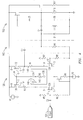
- FIG. 4 is a schematic representation of hybrid load single-stage differential amplifier in accordance with the present invention, as may be integrated in a wireless telemetry system.
- Circuitry 120 may be arranged to amplify the AC output signal from a low-level output sensor (e.g., a strain gauge) and the amplified output signal from circuitry 120 may be signal-conditioned through a high-pass filter 160 and passed to a voltage-controlled oscillator 162, which may be configured to modulate a radiofrequency (RF) carrier.
- a low-level output sensor e.g., a strain gauge
- the relatively high-gain which can be obtained with the present invention can advantageously avoid a need of multiple stages of amplification (AC amplifiers), thereby incrementally reducing costs as well as providing substantial signal integrity (e.g., improved signal-to-noise ratio) and increasing system reliability (e.g., less interconnections).
Landscapes
- Engineering & Computer Science (AREA)
- Mechanical Engineering (AREA)
- General Engineering & Computer Science (AREA)
- Physics & Mathematics (AREA)
- General Physics & Mathematics (AREA)
- Power Engineering (AREA)
- Amplifiers (AREA)
- Measurement Of Length, Angles, Or The Like Using Electric Or Magnetic Means (AREA)
Claims (12)
- Schaltung (120), die so ausgelegt ist, dass sie in einer Umgebung einer Turbine mit einer maximalen Betriebstemperatur von über 300°C arbeitet, wobei die Schaltung (120) Folgendes umfasst:ein Erfassungselement (101) zum Anordnen an einer Komponente (20) der Turbine zwecks Erfassens eines Parameters der Komponente (20) und Bereitstellung einer Spannung, die den erfassten Parameter angibt,einen Differenzverstärker (122) mit einem Eingangsanschluss (124), der an das Erfassungselement (101) angeschlossen ist und so die Spannung aufnimmt, die den erfassten Parameter angibt, undeine Hybridlastschaltung (125), die mit dem Differenzverstärker (122) wechselstromgekoppelt ist, wobei der Differenzverstärker (122) und die Hybridlastschaltung (125) bei einer Verwendung der Schaltung (120) in der Umgebung der Turbine angeordnet sind,wobei der Differenzverstärker (122) ein erstes Paar Haltleiterschalter (126, 128) und die Hybridlastschaltung (125) ein zweites Paar Halbleiterschalter (130, 132) umfasst, wobei jedes Schalterpaar (126, 128, 130, 132) jeweils Drain-(D), Source- (S) und Gate-Anschluss (G) aufweist, wobei die Hybridlastschaltung (125) ferner einen Widerstand-Kondensator-Schaltkreis (134) umfasst, der so angeordnet ist, dass er einen Weg zu einer Wechselspannungssignalkomponente in Bezug zu dem Drain-Anschluss (D) des Schalters (126) des ersten Paars Halbleiterschalter (126, 128) bereitstellt, das die den erfassten Parameter angebende Spannung aufnimmt,wobei der Widerstand-Kondensator-Schaltkreis (134) an einen Knoten (136) angeschlossen ist, der mit den jeweiligen Gate-Anschlüssen (G) des zweiten Paars Halbleiterschalter (130, 132) parallelgeschaltet ist,wobei die Sources (S) des zweiten Paars Halbleiterschalter (130, 132) jeweils an die Drains (D) des ersten Paars Halbleiterschalter (126, 128) angeschlossen sind.
- Schaltung (120) nach Anspruch 1, wobei eine erste Leitung eines Widerstands (142) des Widerstand-Kondensator-Schaltkreises (134) an den Knoten (136) angeschlossen und eine zweite Leitung an Masse (135) gelegt ist.
- Schaltung (120) nach Anspruch 2, wobei eine erste Leitung des Kondensators (140) des Widerstand-Kondensator-Schaltkreises (134) an den Knoten (136) und eine zweite Leitung an den Drain-Anschluss (D) des Schalters (126) des ersten Paars Halbleiterschalter (126, 128) angeschlossen ist, der die den erfassten Parameter angebende Spannung aufnimmt.
- Schaltung (120) nach Anspruch 1, wobei die Hybridlastschaltung (125) ferner einen ersten Widerstand (144) umfasst, der von einem Source-Anschluss (S) eines Schalters (130) des zweiten Paars Halbleiterschalter (130, 132) aus an einen Drain-Anschluss (D) eines Schalters (126) des ersten Paars Halbleiterschalter (126, 128) gekoppelt ist.
- Schaltung (120) nach Anspruch 4, wobei die Hybridlastschaltung (125) ferner einen zweiten Widerstand (146) umfasst, der von einem Source-Anschluss (S) des anderen Schalters (132) des zweiten Paars Halbleiterschalter (130, 132) aus an einen Drain-Anschluss (D) des anderen Schalters (128) des ersten Paars Halbleiterschalter (126, 128) gekoppelt ist.
- Schaltung (120) nach Anspruch 1, wobei der Differenzverstärker (122) einen einstufigen Differenzverstärker umfasst.
- Schaltung (120) nach Anspruch 1, wobei das erste beziehungsweise das zweite Paar Halbleiterschalter (126, 128, 130, 132) eine Schaltung ohne komplementäre Halbleiterschalterpaare umfasst.
- Schaltung (120) nach Anspruch 1, wobei das erste beziehungsweise das zweite Paar Halbleiterschalter (126, 128, 130, 132) n-Kanal-SFET-Schalter (SFET - Sperrschicht-Feldeffekttransistor) umfassen.
- Schaltung (120) nach Anspruch 1, wobei das erste beziehungsweise das zweite Paar Halbleiterschalter (126, 128, 130, 132) ein jeweiliges breitlückiges Hochtemperaturmaterial umfasst.
- Schaltung (120) nach Anspruch 9, wobei das breitlückige Hochtemperaturmaterial aus der Gruppe ausgewählt ist, die aus SiC, AlN, GaN, AlGaN, GaAs, GaP, InP, AlGaAs, AlGaP, AlInGaP und GaAsAlN besteht.
- Schaltung (120) nach Anspruch 1, wobei das Erfassungselement (101) einen Dehnmessstreifen zum Erfassen einer Dehnung der Komponente (20) umfasst und die Spannung die erfasste Dehnung der Komponente (20) angibt.
- Telemetriesystem (24, 26) mit der Schaltung (120) nach Anspruch 1.
Applications Claiming Priority (2)
| Application Number | Priority Date | Filing Date | Title |
|---|---|---|---|
| US13/537,572 US8766720B2 (en) | 2012-06-29 | 2012-06-29 | Hybrid load differential amplifier operable in a high temperature environment of a turbine engine |
| PCT/US2013/044268 WO2014004004A1 (en) | 2012-06-29 | 2013-06-05 | Hybrid load differential amplifier operable in a high temperature environment of a turbine engine |
Publications (2)
| Publication Number | Publication Date |
|---|---|
| EP2867635A1 EP2867635A1 (de) | 2015-05-06 |
| EP2867635B1 true EP2867635B1 (de) | 2018-08-01 |
Family
ID=48692648
Family Applications (1)
| Application Number | Title | Priority Date | Filing Date |
|---|---|---|---|
| EP13731195.7A Not-in-force EP2867635B1 (de) | 2012-06-29 | 2013-06-05 | Hybrider lastdifferenzverstärker betriebsfähig in einer hochtemperaturumgebung eines turbinenmotors |
Country Status (7)
| Country | Link |
|---|---|
| US (1) | US8766720B2 (de) |
| EP (1) | EP2867635B1 (de) |
| JP (1) | JP2015522818A (de) |
| KR (1) | KR101962327B1 (de) |
| CN (1) | CN104520684B (de) |
| CA (1) | CA2877667A1 (de) |
| WO (1) | WO2014004004A1 (de) |
Families Citing this family (2)
| Publication number | Priority date | Publication date | Assignee | Title |
|---|---|---|---|---|
| DE202015009751U1 (de) | 2014-12-05 | 2019-11-26 | Analog Devices Inc. | Lastschaltkreis mit hoher Verstärkung für ein Differenzialpaar unter Verwendung von Verarmungsmodustransistoren |
| CN111678426B (zh) * | 2020-07-31 | 2021-04-27 | 宁波市交建工程监理咨询有限公司 | 一种基于物联网的建筑结构应变无线监测系统 |
Family Cites Families (16)
| Publication number | Priority date | Publication date | Assignee | Title |
|---|---|---|---|---|
| US4166243A (en) * | 1978-04-21 | 1979-08-28 | General Motors Corporation | Thermocouple failure detector |
| DE4417228A1 (de) * | 1994-05-17 | 1995-11-23 | Michael Dr Altwein | Dehnungsmeßstreifen-Meßanordnung, Verwendung derselben und Modulationsverstärker für derartige Meßanordnungen |
| US6828802B2 (en) * | 2002-08-16 | 2004-12-07 | Rosemount Inc. | Pressure measurement device including a capacitive sensor in an amplifier feedback path |
| US20050198967A1 (en) * | 2002-09-23 | 2005-09-15 | Siemens Westinghouse Power Corp. | Smart component for use in an operating environment |
| FR2869981B1 (fr) * | 2004-05-04 | 2006-07-21 | Snr Roulements Sa | Roulement capteur de deformations comprenant quatre jauges de contraintes |
| US7132883B2 (en) | 2005-02-08 | 2006-11-07 | Maxim Integrated Products, Inc. | Chopper chopper-stabilized instrumentation and operational amplifiers |
| US7317356B2 (en) * | 2005-03-02 | 2008-01-08 | Alfred E. Mann Foundation For Scientific Research | Ultra low-frequency response, DC-blocked low-noise amplifier |
| US8519866B2 (en) | 2007-11-08 | 2013-08-27 | Siemens Energy, Inc. | Wireless telemetry for instrumented component |
| FR2934182B1 (fr) | 2008-07-24 | 2010-09-10 | Michelin Soc Tech | Installation et procede de raclage d'une selle d'un melangeur. |
| US8033722B2 (en) | 2008-08-01 | 2011-10-11 | Siemens Energy, Inc. | Thermocouple for gas turbine environments |
| US8220990B2 (en) | 2008-08-15 | 2012-07-17 | Siemens Energy, Inc. | Wireless telemetry electronic circuit package for high temperature environments |
| US8023269B2 (en) | 2008-08-15 | 2011-09-20 | Siemens Energy, Inc. | Wireless telemetry electronic circuit board for high temperature environments |
| US8092080B2 (en) | 2008-08-15 | 2012-01-10 | Siemens Energy, Inc. | Wireless telemetry circuit structure for measuring temperature in high temperature environments |
| US8223036B2 (en) * | 2008-08-15 | 2012-07-17 | Siemens Energy, Inc. | Wireless telemetry electronic circuitry for measuring strain in high-temperature environments |
| US8076587B2 (en) | 2008-09-26 | 2011-12-13 | Siemens Energy, Inc. | Printed circuit board for harsh environments |
| US7696817B1 (en) | 2008-10-17 | 2010-04-13 | Maxim Integrated Products, Inc. | Auto-gain correction and common mode voltage cancellation in a precision amplifier |
-
2012
- 2012-06-29 US US13/537,572 patent/US8766720B2/en not_active Expired - Fee Related
-
2013
- 2013-06-05 EP EP13731195.7A patent/EP2867635B1/de not_active Not-in-force
- 2013-06-05 WO PCT/US2013/044268 patent/WO2014004004A1/en not_active Ceased
- 2013-06-05 CA CA2877667A patent/CA2877667A1/en not_active Abandoned
- 2013-06-05 JP JP2015520219A patent/JP2015522818A/ja active Pending
- 2013-06-05 KR KR1020147036733A patent/KR101962327B1/ko not_active Expired - Fee Related
- 2013-06-05 CN CN201380037565.0A patent/CN104520684B/zh not_active Expired - Fee Related
Also Published As
| Publication number | Publication date |
|---|---|
| KR101962327B1 (ko) | 2019-03-26 |
| WO2014004004A1 (en) | 2014-01-03 |
| EP2867635A1 (de) | 2015-05-06 |
| JP2015522818A (ja) | 2015-08-06 |
| KR20170035360A (ko) | 2017-03-31 |
| CN104520684B (zh) | 2017-05-03 |
| CA2877667A1 (en) | 2014-01-03 |
| WO2014004004A8 (en) | 2015-01-15 |
| US8766720B2 (en) | 2014-07-01 |
| US20140002191A1 (en) | 2014-01-02 |
| CN104520684A (zh) | 2015-04-15 |
Similar Documents
| Publication | Publication Date | Title |
|---|---|---|
| US8823456B2 (en) | Cancellation of gain change due to amplifier self-heating | |
| US8952674B2 (en) | Voltage regulator circuitry operable in a high temperature environment of a turbine engine | |
| WO2005022740A3 (en) | Method and apparatus providing integrated load matching using adaptive power amplifier compensation | |
| EP1667331A4 (de) | Verstärker-schaltung und verstärkungs-verfahren | |
| US8766720B2 (en) | Hybrid load differential amplifier operable in a high temperature environment of a turbine engine | |
| EP2870443B1 (de) | Zerhackerschaltung für den betrieb in einer hochtemperaturumgebung eines turbinenmotors | |
| WO2014209483A1 (en) | Loss-less frequency dependent dicke-switched radiometer | |
| KR102101181B1 (ko) | 고온 환경들을 위한 전자 회로소자 | |
| US7709998B2 (en) | Measurement system for measuring cylinder pressure in an internal combustion engine | |
| US9939315B2 (en) | Two-wire electronics interface sensor with integrated mechanical transducing and temperature monitoring capability | |
| JP2004506186A (ja) | 高周波数および低周波数帯域の双方出力トランスデューサ | |
| Sathya | Design of a Low Noise Signal Amplifier for Sensor Signal Amplification | |
| JP2016014689A (ja) | 衝撃電流検出装置 | |
| RU2394360C1 (ru) | Каскодный дифференциальный усилитель с повышенным входным сопротивлением | |
| KR20050028885A (ko) | 동작 전류 측정 장치를 구비한 hf-전력 증폭기 | |
| KR102021591B1 (ko) | 디지털 신호 출력 고주파 센서 및 그 동작방법 | |
| CN104485936B (zh) | 一种高温二选一开关电路 | |
| KR102134892B1 (ko) | 공급 전압 변조 장치 및 이를 구비하는 전력 증폭기 | |
| CN117538590A (zh) | 一种霍尔传感器电路和电子设备 | |
| US8384481B2 (en) | Signal amplification device and signal amplification method | |
| CA2774833A1 (en) | Personal active electromagnetic frequency attenuator | |
| Rajak | Design of a CMOS signal processing system | |
| Carlosena et al. | Design of Low-Cost Smart Accelerometers |
Legal Events
| Date | Code | Title | Description |
|---|---|---|---|
| PUAI | Public reference made under article 153(3) epc to a published international application that has entered the european phase |
Free format text: ORIGINAL CODE: 0009012 |
|
| 17P | Request for examination filed |
Effective date: 20141211 |
|
| AK | Designated contracting states |
Kind code of ref document: A1 Designated state(s): AL AT BE BG CH CY CZ DE DK EE ES FI FR GB GR HR HU IE IS IT LI LT LU LV MC MK MT NL NO PL PT RO RS SE SI SK SM TR |
|
| AX | Request for extension of the european patent |
Extension state: BA ME |
|
| DAX | Request for extension of the european patent (deleted) | ||
| RAP1 | Party data changed (applicant data changed or rights of an application transferred) |
Owner name: CREE FAYETTEVILLE, INC. Owner name: SIEMENS ENERGY, INC. |
|
| STAA | Information on the status of an ep patent application or granted ep patent |
Free format text: STATUS: EXAMINATION IS IN PROGRESS |
|
| 17Q | First examination report despatched |
Effective date: 20161104 |
|
| GRAP | Despatch of communication of intention to grant a patent |
Free format text: ORIGINAL CODE: EPIDOSNIGR1 |
|
| STAA | Information on the status of an ep patent application or granted ep patent |
Free format text: STATUS: GRANT OF PATENT IS INTENDED |
|
| INTG | Intention to grant announced |
Effective date: 20180219 |
|
| GRAS | Grant fee paid |
Free format text: ORIGINAL CODE: EPIDOSNIGR3 |
|
| GRAA | (expected) grant |
Free format text: ORIGINAL CODE: 0009210 |
|
| STAA | Information on the status of an ep patent application or granted ep patent |
Free format text: STATUS: THE PATENT HAS BEEN GRANTED |
|
| AK | Designated contracting states |
Kind code of ref document: B1 Designated state(s): AL AT BE BG CH CY CZ DE DK EE ES FI FR GB GR HR HU IE IS IT LI LT LU LV MC MK MT NL NO PL PT RO RS SE SI SK SM TR |
|
| REG | Reference to a national code |
Ref country code: GB Ref legal event code: FG4D |
|
| REG | Reference to a national code |
Ref country code: CH Ref legal event code: EP Ref country code: AT Ref legal event code: REF Ref document number: 1024856 Country of ref document: AT Kind code of ref document: T Effective date: 20180815 |
|
| REG | Reference to a national code |
Ref country code: IE Ref legal event code: FG4D |
|
| REG | Reference to a national code |
Ref country code: DE Ref legal event code: R096 Ref document number: 602013041184 Country of ref document: DE |
|
| REG | Reference to a national code |
Ref country code: NL Ref legal event code: MP Effective date: 20180801 |
|
| REG | Reference to a national code |
Ref country code: LT Ref legal event code: MG4D |
|
| REG | Reference to a national code |
Ref country code: AT Ref legal event code: MK05 Ref document number: 1024856 Country of ref document: AT Kind code of ref document: T Effective date: 20180801 |
|
| PG25 | Lapsed in a contracting state [announced via postgrant information from national office to epo] |
Ref country code: LT Free format text: LAPSE BECAUSE OF FAILURE TO SUBMIT A TRANSLATION OF THE DESCRIPTION OR TO PAY THE FEE WITHIN THE PRESCRIBED TIME-LIMIT Effective date: 20180801 Ref country code: IS Free format text: LAPSE BECAUSE OF FAILURE TO SUBMIT A TRANSLATION OF THE DESCRIPTION OR TO PAY THE FEE WITHIN THE PRESCRIBED TIME-LIMIT Effective date: 20181201 Ref country code: PL Free format text: LAPSE BECAUSE OF FAILURE TO SUBMIT A TRANSLATION OF THE DESCRIPTION OR TO PAY THE FEE WITHIN THE PRESCRIBED TIME-LIMIT Effective date: 20180801 Ref country code: AT Free format text: LAPSE BECAUSE OF FAILURE TO SUBMIT A TRANSLATION OF THE DESCRIPTION OR TO PAY THE FEE WITHIN THE PRESCRIBED TIME-LIMIT Effective date: 20180801 Ref country code: BG Free format text: LAPSE BECAUSE OF FAILURE TO SUBMIT A TRANSLATION OF THE DESCRIPTION OR TO PAY THE FEE WITHIN THE PRESCRIBED TIME-LIMIT Effective date: 20181101 Ref country code: NL Free format text: LAPSE BECAUSE OF FAILURE TO SUBMIT A TRANSLATION OF THE DESCRIPTION OR TO PAY THE FEE WITHIN THE PRESCRIBED TIME-LIMIT Effective date: 20180801 Ref country code: GR Free format text: LAPSE BECAUSE OF FAILURE TO SUBMIT A TRANSLATION OF THE DESCRIPTION OR TO PAY THE FEE WITHIN THE PRESCRIBED TIME-LIMIT Effective date: 20181102 Ref country code: NO Free format text: LAPSE BECAUSE OF FAILURE TO SUBMIT A TRANSLATION OF THE DESCRIPTION OR TO PAY THE FEE WITHIN THE PRESCRIBED TIME-LIMIT Effective date: 20181101 Ref country code: SE Free format text: LAPSE BECAUSE OF FAILURE TO SUBMIT A TRANSLATION OF THE DESCRIPTION OR TO PAY THE FEE WITHIN THE PRESCRIBED TIME-LIMIT Effective date: 20180801 Ref country code: RS Free format text: LAPSE BECAUSE OF FAILURE TO SUBMIT A TRANSLATION OF THE DESCRIPTION OR TO PAY THE FEE WITHIN THE PRESCRIBED TIME-LIMIT Effective date: 20180801 Ref country code: FI Free format text: LAPSE BECAUSE OF FAILURE TO SUBMIT A TRANSLATION OF THE DESCRIPTION OR TO PAY THE FEE WITHIN THE PRESCRIBED TIME-LIMIT Effective date: 20180801 |
|
| PG25 | Lapsed in a contracting state [announced via postgrant information from national office to epo] |
Ref country code: HR Free format text: LAPSE BECAUSE OF FAILURE TO SUBMIT A TRANSLATION OF THE DESCRIPTION OR TO PAY THE FEE WITHIN THE PRESCRIBED TIME-LIMIT Effective date: 20180801 Ref country code: AL Free format text: LAPSE BECAUSE OF FAILURE TO SUBMIT A TRANSLATION OF THE DESCRIPTION OR TO PAY THE FEE WITHIN THE PRESCRIBED TIME-LIMIT Effective date: 20180801 Ref country code: LV Free format text: LAPSE BECAUSE OF FAILURE TO SUBMIT A TRANSLATION OF THE DESCRIPTION OR TO PAY THE FEE WITHIN THE PRESCRIBED TIME-LIMIT Effective date: 20180801 |
|
| PG25 | Lapsed in a contracting state [announced via postgrant information from national office to epo] |
Ref country code: CZ Free format text: LAPSE BECAUSE OF FAILURE TO SUBMIT A TRANSLATION OF THE DESCRIPTION OR TO PAY THE FEE WITHIN THE PRESCRIBED TIME-LIMIT Effective date: 20180801 Ref country code: RO Free format text: LAPSE BECAUSE OF FAILURE TO SUBMIT A TRANSLATION OF THE DESCRIPTION OR TO PAY THE FEE WITHIN THE PRESCRIBED TIME-LIMIT Effective date: 20180801 Ref country code: EE Free format text: LAPSE BECAUSE OF FAILURE TO SUBMIT A TRANSLATION OF THE DESCRIPTION OR TO PAY THE FEE WITHIN THE PRESCRIBED TIME-LIMIT Effective date: 20180801 Ref country code: ES Free format text: LAPSE BECAUSE OF FAILURE TO SUBMIT A TRANSLATION OF THE DESCRIPTION OR TO PAY THE FEE WITHIN THE PRESCRIBED TIME-LIMIT Effective date: 20180801 |
|
| REG | Reference to a national code |
Ref country code: DE Ref legal event code: R097 Ref document number: 602013041184 Country of ref document: DE |
|
| PG25 | Lapsed in a contracting state [announced via postgrant information from national office to epo] |
Ref country code: SM Free format text: LAPSE BECAUSE OF FAILURE TO SUBMIT A TRANSLATION OF THE DESCRIPTION OR TO PAY THE FEE WITHIN THE PRESCRIBED TIME-LIMIT Effective date: 20180801 Ref country code: SK Free format text: LAPSE BECAUSE OF FAILURE TO SUBMIT A TRANSLATION OF THE DESCRIPTION OR TO PAY THE FEE WITHIN THE PRESCRIBED TIME-LIMIT Effective date: 20180801 Ref country code: DK Free format text: LAPSE BECAUSE OF FAILURE TO SUBMIT A TRANSLATION OF THE DESCRIPTION OR TO PAY THE FEE WITHIN THE PRESCRIBED TIME-LIMIT Effective date: 20180801 |
|
| PLBE | No opposition filed within time limit |
Free format text: ORIGINAL CODE: 0009261 |
|
| STAA | Information on the status of an ep patent application or granted ep patent |
Free format text: STATUS: NO OPPOSITION FILED WITHIN TIME LIMIT |
|
| 26N | No opposition filed |
Effective date: 20190503 |
|
| PG25 | Lapsed in a contracting state [announced via postgrant information from national office to epo] |
Ref country code: SI Free format text: LAPSE BECAUSE OF FAILURE TO SUBMIT A TRANSLATION OF THE DESCRIPTION OR TO PAY THE FEE WITHIN THE PRESCRIBED TIME-LIMIT Effective date: 20180801 |
|
| PGFP | Annual fee paid to national office [announced via postgrant information from national office to epo] |
Ref country code: IT Payment date: 20190627 Year of fee payment: 7 Ref country code: GB Payment date: 20190610 Year of fee payment: 7 |
|
| REG | Reference to a national code |
Ref country code: DE Ref legal event code: R119 Ref document number: 602013041184 Country of ref document: DE |
|
| PG25 | Lapsed in a contracting state [announced via postgrant information from national office to epo] |
Ref country code: MC Free format text: LAPSE BECAUSE OF FAILURE TO SUBMIT A TRANSLATION OF THE DESCRIPTION OR TO PAY THE FEE WITHIN THE PRESCRIBED TIME-LIMIT Effective date: 20180801 |
|
| REG | Reference to a national code |
Ref country code: CH Ref legal event code: PL |
|
| REG | Reference to a national code |
Ref country code: BE Ref legal event code: MM Effective date: 20190630 |
|
| PG25 | Lapsed in a contracting state [announced via postgrant information from national office to epo] |
Ref country code: TR Free format text: LAPSE BECAUSE OF FAILURE TO SUBMIT A TRANSLATION OF THE DESCRIPTION OR TO PAY THE FEE WITHIN THE PRESCRIBED TIME-LIMIT Effective date: 20180801 |
|
| PG25 | Lapsed in a contracting state [announced via postgrant information from national office to epo] |
Ref country code: DE Free format text: LAPSE BECAUSE OF NON-PAYMENT OF DUE FEES Effective date: 20200101 Ref country code: IE Free format text: LAPSE BECAUSE OF NON-PAYMENT OF DUE FEES Effective date: 20190605 |
|
| PG25 | Lapsed in a contracting state [announced via postgrant information from national office to epo] |
Ref country code: LU Free format text: LAPSE BECAUSE OF NON-PAYMENT OF DUE FEES Effective date: 20190605 Ref country code: LI Free format text: LAPSE BECAUSE OF NON-PAYMENT OF DUE FEES Effective date: 20190630 Ref country code: BE Free format text: LAPSE BECAUSE OF NON-PAYMENT OF DUE FEES Effective date: 20190630 Ref country code: CH Free format text: LAPSE BECAUSE OF NON-PAYMENT OF DUE FEES Effective date: 20190630 |
|
| PG25 | Lapsed in a contracting state [announced via postgrant information from national office to epo] |
Ref country code: FR Free format text: LAPSE BECAUSE OF NON-PAYMENT OF DUE FEES Effective date: 20190630 Ref country code: PT Free format text: LAPSE BECAUSE OF FAILURE TO SUBMIT A TRANSLATION OF THE DESCRIPTION OR TO PAY THE FEE WITHIN THE PRESCRIBED TIME-LIMIT Effective date: 20181201 |
|
| GBPC | Gb: european patent ceased through non-payment of renewal fee |
Effective date: 20200605 |
|
| PG25 | Lapsed in a contracting state [announced via postgrant information from national office to epo] |
Ref country code: GB Free format text: LAPSE BECAUSE OF NON-PAYMENT OF DUE FEES Effective date: 20200605 |
|
| PG25 | Lapsed in a contracting state [announced via postgrant information from national office to epo] |
Ref country code: CY Free format text: LAPSE BECAUSE OF FAILURE TO SUBMIT A TRANSLATION OF THE DESCRIPTION OR TO PAY THE FEE WITHIN THE PRESCRIBED TIME-LIMIT Effective date: 20180801 |
|
| PG25 | Lapsed in a contracting state [announced via postgrant information from national office to epo] |
Ref country code: HU Free format text: LAPSE BECAUSE OF FAILURE TO SUBMIT A TRANSLATION OF THE DESCRIPTION OR TO PAY THE FEE WITHIN THE PRESCRIBED TIME-LIMIT; INVALID AB INITIO Effective date: 20130605 Ref country code: MT Free format text: LAPSE BECAUSE OF FAILURE TO SUBMIT A TRANSLATION OF THE DESCRIPTION OR TO PAY THE FEE WITHIN THE PRESCRIBED TIME-LIMIT Effective date: 20180801 |
|
| PG25 | Lapsed in a contracting state [announced via postgrant information from national office to epo] |
Ref country code: IT Free format text: LAPSE BECAUSE OF NON-PAYMENT OF DUE FEES Effective date: 20200605 |
|
| PG25 | Lapsed in a contracting state [announced via postgrant information from national office to epo] |
Ref country code: MK Free format text: LAPSE BECAUSE OF FAILURE TO SUBMIT A TRANSLATION OF THE DESCRIPTION OR TO PAY THE FEE WITHIN THE PRESCRIBED TIME-LIMIT Effective date: 20180801 |