EP2867570B1 - Quick acting male coupling for conveying pressurized fluids - Google Patents
Quick acting male coupling for conveying pressurized fluids Download PDFInfo
- Publication number
- EP2867570B1 EP2867570B1 EP13762242.9A EP13762242A EP2867570B1 EP 2867570 B1 EP2867570 B1 EP 2867570B1 EP 13762242 A EP13762242 A EP 13762242A EP 2867570 B1 EP2867570 B1 EP 2867570B1
- Authority
- EP
- European Patent Office
- Prior art keywords
- male coupling
- quick acting
- valve body
- base
- conveying fluids
- Prior art date
- Legal status (The legal status is an assumption and is not a legal conclusion. Google has not performed a legal analysis and makes no representation as to the accuracy of the status listed.)
- Active
Links
Images



Classifications
-
- F—MECHANICAL ENGINEERING; LIGHTING; HEATING; WEAPONS; BLASTING
- F16—ENGINEERING ELEMENTS AND UNITS; GENERAL MEASURES FOR PRODUCING AND MAINTAINING EFFECTIVE FUNCTIONING OF MACHINES OR INSTALLATIONS; THERMAL INSULATION IN GENERAL
- F16L—PIPES; JOINTS OR FITTINGS FOR PIPES; SUPPORTS FOR PIPES, CABLES OR PROTECTIVE TUBING; MEANS FOR THERMAL INSULATION IN GENERAL
- F16L37/00—Couplings of the quick-acting type
- F16L37/28—Couplings of the quick-acting type with fluid cut-off means
- F16L37/30—Couplings of the quick-acting type with fluid cut-off means with fluid cut-off means in each of two pipe-end fittings
- F16L37/32—Couplings of the quick-acting type with fluid cut-off means with fluid cut-off means in each of two pipe-end fittings at least one of two lift valves being opened automatically when the coupling is applied
-
- F—MECHANICAL ENGINEERING; LIGHTING; HEATING; WEAPONS; BLASTING
- F16—ENGINEERING ELEMENTS AND UNITS; GENERAL MEASURES FOR PRODUCING AND MAINTAINING EFFECTIVE FUNCTIONING OF MACHINES OR INSTALLATIONS; THERMAL INSULATION IN GENERAL
- F16L—PIPES; JOINTS OR FITTINGS FOR PIPES; SUPPORTS FOR PIPES, CABLES OR PROTECTIVE TUBING; MEANS FOR THERMAL INSULATION IN GENERAL
- F16L37/00—Couplings of the quick-acting type
- F16L37/28—Couplings of the quick-acting type with fluid cut-off means
- F16L37/30—Couplings of the quick-acting type with fluid cut-off means with fluid cut-off means in each of two pipe-end fittings
- F16L37/32—Couplings of the quick-acting type with fluid cut-off means with fluid cut-off means in each of two pipe-end fittings at least one of two lift valves being opened automatically when the coupling is applied
- F16L37/34—Couplings of the quick-acting type with fluid cut-off means with fluid cut-off means in each of two pipe-end fittings at least one of two lift valves being opened automatically when the coupling is applied at least one of the lift valves being of the sleeve type, i.e. a sleeve being telescoped over an inner cylindrical wall
-
- F—MECHANICAL ENGINEERING; LIGHTING; HEATING; WEAPONS; BLASTING
- F16—ENGINEERING ELEMENTS AND UNITS; GENERAL MEASURES FOR PRODUCING AND MAINTAINING EFFECTIVE FUNCTIONING OF MACHINES OR INSTALLATIONS; THERMAL INSULATION IN GENERAL
- F16L—PIPES; JOINTS OR FITTINGS FOR PIPES; SUPPORTS FOR PIPES, CABLES OR PROTECTIVE TUBING; MEANS FOR THERMAL INSULATION IN GENERAL
- F16L37/00—Couplings of the quick-acting type
- F16L37/28—Couplings of the quick-acting type with fluid cut-off means
- F16L37/38—Couplings of the quick-acting type with fluid cut-off means with fluid cut-off means in only one of two pipe-end fittings
- F16L37/40—Couplings of the quick-acting type with fluid cut-off means with fluid cut-off means in only one of two pipe-end fittings with a lift valve being opened automatically when the coupling is applied
-
- F—MECHANICAL ENGINEERING; LIGHTING; HEATING; WEAPONS; BLASTING
- F16—ENGINEERING ELEMENTS AND UNITS; GENERAL MEASURES FOR PRODUCING AND MAINTAINING EFFECTIVE FUNCTIONING OF MACHINES OR INSTALLATIONS; THERMAL INSULATION IN GENERAL
- F16L—PIPES; JOINTS OR FITTINGS FOR PIPES; SUPPORTS FOR PIPES, CABLES OR PROTECTIVE TUBING; MEANS FOR THERMAL INSULATION IN GENERAL
- F16L37/00—Couplings of the quick-acting type
- F16L37/28—Couplings of the quick-acting type with fluid cut-off means
- F16L37/38—Couplings of the quick-acting type with fluid cut-off means with fluid cut-off means in only one of two pipe-end fittings
- F16L37/40—Couplings of the quick-acting type with fluid cut-off means with fluid cut-off means in only one of two pipe-end fittings with a lift valve being opened automatically when the coupling is applied
- F16L37/413—Couplings of the quick-acting type with fluid cut-off means with fluid cut-off means in only one of two pipe-end fittings with a lift valve being opened automatically when the coupling is applied the lift valve being of the sleeve type, i.e. a sleeve being telescoped over an inner cylindrical wall
Definitions
- the present invention refers to a quick acting male coupling for conveying pressurized fluids that can be utilized in agricultural or industrial applications.
- a quick acting male coupling comprising a longitudinal valve body having, along its longitudinal axis, an open cavity, a shutter that is axially mobile in the cavity of the valve body in opposition to and by action of a helical spring and that can be positioned against a valve seat for closure of the passage of fluid through the cavity of the valve body, and a guide element for the shutter, pressed by the helical spring against a mechanical stop.
- the quick acting male coupling can be coupled to a quick acting female coupling, and the locking of one to the other is generally obtained with races of balls that can be activated by a ring nut mounted in an axially translatable manner on the female coupling.
- Couplings of this sort are designed to prevent partial closure of the shutter with flow inversion and the occurrence of flow rate peaks.
- these couplings must be capable of ensuring that thorough cleanliness is maintained in the coupling and decoupling procedures between the male coupling and the female coupling so as to prevent leakage of fluid into the environment and to prevent absorption of air in the fluid.
- the technical task of the present invention is to realize a quick acting male coupling for pressurized fluids that makes it possible to eliminate the reported technical drawbacks of the prior art.
- one aim of the invention is to realize a quick acting male coupling for pressurized fluids that optimizes the maximum flow rate that is achievable, while ensuring safe use for the operator, adequate reliability and maintenance of clean conditions in the procedures for coupling and decoupling with a quick acting female coupling.
- a quick acting male coupling for conveying fluids comprising a longitudinal valve body having, along its longitudinal axis, an open cavity, a shutter that is axially mobile in the cavity of the valve body in opposition to and by action of a helical spring and that can be positioned against a valve seat for closure of the passage of fluid through the cavity of the valve body, and a guide element for the shutter, pressed by the helical spring against a mechanical stop, wherein that said shutter comprises an axially hollow rod, and in that said guide element comprises a base, a guide pin that axially extends out from the base, and a plurality of fins for centring the guide element which surround the guide pin and extend out from the base on the same side as the guide pin, said rod being fitted on the said guide pin with the interposition of said helical spring, which is inserted in the cavity of the rod and fitted on the guide pin.
- One of the principal advantages resulting from the adoption of a structure such as this for the quick acting male coupling consists in the fact that the opening for outflow of the fluid through the guide element is optimized so as to maximize the maximum flow rate achievable.
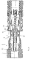
- the quick acting male coupling for conveying fluids comprises a longitudinal valve body 1 having, along its longitudinal axis 2, an open cavity 3, a shutter 4 that is axially mobile in the cavity 3 of the valve body 1 in opposition to and by action of a helical spring 5 and that can be positioned against a valve seat 6 for closure of the passage of fluid through the cavity 3 of the valve body 1, and a guide element 7 for the shutter 4, pressed by the helical spring 5 against a mechanical stop 8 preferably defined by the internal lateral surface of the valve body 1.
- the valve body 1 has a modular structure comprising a first hollow part 1a that defines the valve seat 6 internally and a second hollow part 1b connecting to an external element, screwed to the first hollow part 1a and internally having the mechanical stop 8 for the guide element 7.
- the shutter 4 comprises a preferably cylindrical and axially hollow rod 9 and a head 10.
- the head 10 exhibits a flat surface 23 at the apex, a cylindrical lateral surface 25 having a protrusion 26 at the perimeter that can be positioned against the valve body 6, and a cone-shaped base surface 24, bevelled at 45° with respect to the axis of the rod 9, and joined to the rod 9 with a wide radius.
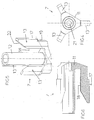
- the guide element 7 comprises a base 11, a preferably cylindrical guide pin 12 that axially extends out from the base 11, and a plurality of fins 13 for centring the guide element 7 which circumscribe the guide pin 12 and extend out from the base 11 on the same side as the guide pin 12.
- the pin 12 and the fins 13 extend out perpendicularly from the base 11.
- the guide element 7 also has an axial drain passage 21 that extends through the base 11 and the pin 12 and it is designed to drain the fluid so as to prevent the occurrence of internal residual pressure levels that block the disassembly of the constituent elements of the male coupling.
- the rod 9 is fitted on the guide pin 12 with the interposition of the helical spring 5, which, in particular, is inserted in the cavity 14 of the rod 9 and fitted on the guide pin 12.
- the helical spring 5 has an axial length that is in any case greater than the length of the guide pin 12, as it is provided with an axial section 15 that is fitted onto the guide pin 12 and an axial section 16 that extends beyond tip of the apex of the guide pin 12.
- helical spring 5 rests against the base 11 and the other end rests against the bottom of the cavity 14 of the rod 9 and the helical spring 5 operates in a state of permanent axial compression between a configuration of maximum axial extension, in which it keeps the guide element 7 against the mechanical stop 8 and the shutter 4 protracted against the valve seat 6 for closure of the passage of fluid through the cavity 3 of the valve body 1 when the male coupling is disconnected from the female coupling, and a configuration of minimum axial extension, in which it keeps the guide element 7 against the mechanical stop 8 when the shutter 4 is retracted for opening the passage of fluid through the cavity 3 of the valve body 1.
- the fins 13 of the guide element 7 have a radially external edge 17 for resting against the internal lateral surface of the valve body 1 and against the mechanical stop 8, as well as radially internal edge 18 that faces the rod 9 and cooperates with the pin 12 in guiding the rod 9.
- the internal lateral surface of the valve body 1 is cylindrical and has a discontinuity in the diameter forming a projecting part 20 that defines the mechanical stop 8.
- each fin 13 correspondingly has a cylindrical-sector conformation coaxial with the internal lateral surface of the valve body 1 and a discontinuity in the diameter, defining a step 19 for resting against the projecting part 20, whereas the radially internal edge 18 of each fin 13 has a cylindrical-sector conformation coaxial with the pin 12.
- the fins 13 are tapered at the apex 22, which facilitates application of the rod 9 on the guide pin 12.
- the base 11 of the guide element 7 advantageously has the shape of an equilateral triangle and a principal lying plane orthogonal to the longitudinal axis 2 of the valve body 1.
- centring fins 13 each extending out from a respective vertex of the triangular base 11.
- the quick acting male coupling has a circumferential perimeter groove 27 in which there can be positioned balls 28 that can be activated by a ring nut 29 brought into position in an axially translatable manner by a quick acting female coupling of a known type for locking the connection with the male coupling.
- the quick acting female coupling comprises an axially hollow modular body 30 made up of a first part 30a that can be associated with the first part 1a of the modular body 1 of the quick acting male coupling and a second part 30b screwed to the first part 30a and connectable to an external element.
- An axial push bar 31 with a flat head 46 is housed in a fixed manner in the modular body 30.
- the push bar 31 comprises a rod 50 that is arranged coaxially in the modular body 30 and a base 32 provided with axial passages 36 for the fluid.
- a first, axially hollow insert 43 fitted coaxially on the axial push bar 31 with which it delimits an interspace 60 for passage of the fluid, a second, axially hollow insert 35 fitted coaxially on the first insert 43, and a third, axially hollow insert 40 fitted coaxially on the second insert 35 are present in the modular body 30.
- the base 32 of the push bar 31 engages with an internal shoulder 33 of the second part 30b of the modular body 30 and has a shoulder 37 that engages with an internal shoulder 34 of the second insert 35, which, in turn, also has an external shoulder 38 that engages with an internal shoulder 39 of the first part 30a of the modular body 30.
- the first part 30a of the modular body 30 thus secures the second insert 35 against the base 32, which is, in turn, secured against the second part 30b of the modular body 30.
- the first insert 43 has an external perimeter flange 45 that is engageable with an internal perimeter flange 48 of the second insert 35 and with an internal perimeter flange at the apex 49 of the third insert 40.
- the second insert 35 has an internal lateral surface for guiding the axial translation of the first insert 43 along the second insert 35 in opposition to and by action of a helical spring 44 interposed between the base 32 of the push bar 31 and an external shoulder 47 of the first insert 43.
- the second insert 35 also has an external lateral surface coupled to the internal lateral surface of the third insert 40 for guiding the axial translation of the third insert 40 along the second insert 35 in opposition to and by action of a helical spring 41 interposed between an external perimeter base flange 42 of the third insert 40 and the external shoulder 38 of the second insert 35.
- the first part 30a of the modular body 30 has an internal lateral surface that is coupled to the external lateral surface of the third insert 40 so as to cooperate in the guided axial translation of the third insert 40.
- the first part 30a also has an internal shoulder 52 with which the external perimeter base flange 42 of the third insert is engageable.
- the first part 30a has a plurality of cone-shaped seats 53 arranged along a circumference of the perimeter of the first part 30a and passing through the thickness of the wall of the first part 30a, where the balls 28 are freely housed.
- Coupling between the quick acting male coupling and the quick acting female coupling takes place in the following manner.
- the quick acting male coupling Prior to coupling, the quick acting male coupling is in a configuration in which the shutter 4, being kept by the spring 5 in a position of abutment against the valve seat 6, closes the axial passage of the fluid through the male coupling.
- the female coupling Prior to coupling, the female coupling is in a configuration in which the first insert 43 is kept by the spring 44 in a protracted position of abutment against the back of the head 46 of the axial push bar 31, thus closing the interspace 60 that affords the axial passage of the fluid through the female coupling, whereas the third insert 40 is kept by the spring 41 in a protracted position, at which the abutment of the external flange 42 thereof is against the internal shoulder 52 of the first part 30a of the modular body 30.
- the head 46 of the push bar 31 intercepts and causes the retraction of the shutter 4 in opposition to the spring 5 until the passage for the fluid through the male coupling is opened, while the head end of the part 1a of the modular body 1, as it pushes against the internal flange 49, initially brings about the retraction of the third insert 40 in opposition to the spring 41, and then owing to the engagement between the internal flange 49 and the external flange 45, also brings about the retraction of the first insert 43 in opposition to the spring 44, with the resulting opening of the interspace 60 affording passage of the fluid through the female coupling.
- the ring nut 29 In order to connect the male coupling and the female coupling, the ring nut 29 must be manually retracted, overpowering the force of the spring 55, until the groove 54 is aligned with the seats 53 in such a manner that a space is created that allows for partial extraction of,the balls 28 from the seats 53 in a radial direction outwards, when the external lateral surface of the part 1a of the modular body 1, by sliding along the internal lateral surface of the part 30a of the modular body 30, intercepts the balls 28.
- the penetration of the male coupling in the female coupling terminates when the groove 27 is aligned with the seats 53.
- the fluid can flow through the opening present between the guide element 7 and the part 1b of the modular body 1, and through the opening present between the shutter 4 and the part 1a of the modular body 1.
- the structure proposed for the quick acting male coupling according to the invention proves to be particularly advantageous in that it maximizes the flow rate of the fluid, optimizing the opening for outflow through the guide element 7.
Landscapes
- Engineering & Computer Science (AREA)
- General Engineering & Computer Science (AREA)
- Mechanical Engineering (AREA)
- Quick-Acting Or Multi-Walled Pipe Joints (AREA)
Applications Claiming Priority (2)
| Application Number | Priority Date | Filing Date | Title |
|---|---|---|---|
| IT001136A ITMI20121136A1 (it) | 2012-06-28 | 2012-06-28 | Innesto rapido idraulico o oleodimamico maschio per fluidi in pressione |
| PCT/IB2013/055318 WO2014002065A1 (en) | 2012-06-28 | 2013-06-28 | Quick acting male coupling for conveying pressurized fluids |
Publications (2)
| Publication Number | Publication Date |
|---|---|
| EP2867570A1 EP2867570A1 (en) | 2015-05-06 |
| EP2867570B1 true EP2867570B1 (en) | 2016-10-19 |
Family
ID=46758854
Family Applications (1)
| Application Number | Title | Priority Date | Filing Date |
|---|---|---|---|
| EP13762242.9A Active EP2867570B1 (en) | 2012-06-28 | 2013-06-28 | Quick acting male coupling for conveying pressurized fluids |
Country Status (4)
| Country | Link |
|---|---|
| EP (1) | EP2867570B1 (it) |
| ES (1) | ES2616494T3 (it) |
| IT (1) | ITMI20121136A1 (it) |
| WO (1) | WO2014002065A1 (it) |
Families Citing this family (2)
| Publication number | Priority date | Publication date | Assignee | Title |
|---|---|---|---|---|
| SE542889C2 (en) * | 2017-09-08 | 2020-08-11 | Steelwrist Ab | Hydraulic coupling device and female coupling unit |
| CN110081251B (zh) * | 2019-05-09 | 2021-08-20 | 爱发科东方真空(成都)有限公司 | 一种扩口管自封型密封接头 |
Family Cites Families (3)
| Publication number | Priority date | Publication date | Assignee | Title |
|---|---|---|---|---|
| DE3509371A1 (de) * | 1985-03-15 | 1986-09-18 | Voswinkel Kg, 5882 Meinerzhagen | Unter druck kuppelbare hydraulik-kupplung |
| IT1270206B (it) * | 1994-06-10 | 1997-04-29 | Faster Srl | Innesto rapido per fluidi sotto pressione |
| DE102005011601A1 (de) * | 2005-03-08 | 2006-09-14 | Roman Seliger Gmbh | Abreißkupplung |
-
2012
- 2012-06-28 IT IT001136A patent/ITMI20121136A1/it unknown
-
2013
- 2013-06-28 ES ES13762242.9T patent/ES2616494T3/es active Active
- 2013-06-28 EP EP13762242.9A patent/EP2867570B1/en active Active
- 2013-06-28 WO PCT/IB2013/055318 patent/WO2014002065A1/en not_active Ceased
Also Published As
| Publication number | Publication date |
|---|---|
| EP2867570A1 (en) | 2015-05-06 |
| WO2014002065A1 (en) | 2014-01-03 |
| ITMI20121136A1 (it) | 2013-12-29 |
| ES2616494T3 (es) | 2017-06-13 |
Similar Documents
| Publication | Publication Date | Title |
|---|---|---|
| US9879811B2 (en) | Quick-fit hydraulic or hydrodynamic coupling for pressurized fluids | |
| US9752713B2 (en) | Female quick-connect coupling element, and a quick-connect coupling incorporating such an element | |
| EP2981753B1 (en) | Quick-fit coupling for pressurised fluid | |
| US4221235A (en) | Quick disconnect coupling | |
| US9964248B2 (en) | Fluid transmission flat-face coupler with frontal annular seal | |
| EP1945989B1 (en) | Threaded coupling with flow shutoff | |
| KR102091505B1 (ko) | 증기 밸브, 밸브 및 증기 터빈 설비 | |
| US20130000763A1 (en) | Sequenced Ball Valve Coupling | |
| EP2943711B1 (en) | Quick connect coupling with a self-resetting retention mechanism | |
| EP2981751B1 (en) | Quick coupling device for pressurised fluid | |
| EP3244114B1 (en) | Integrated flush-face cartridge | |
| US10036502B2 (en) | Fluid transmission coupling with independent member pressure relieving cam | |
| EP3574248B2 (en) | Flat face female hydraulic coupling | |
| US9982515B2 (en) | Fusible, resettable lock open device | |
| BR112018009578B1 (pt) | Elemento de acoplamento para acoplamento para a conexão de linhas de meio de pressão | |
| EP2867570B1 (en) | Quick acting male coupling for conveying pressurized fluids | |
| US9140399B2 (en) | Quick coupling | |
| CN104500795A (zh) | 管道爆裂自动保护装置 | |
| NL2013682B1 (en) | Assemblies of a cylinder and a coupling part and/or of a line and a complementary coupling part, a coupling part, a complementary coupling part and a coupling defined by a coupling part and a complementary coupling part. | |
| NZ721042B2 (en) | Fluid transmission flat-face coupler with frontal annular seal | |
| NZ721040B2 (en) | Fluid transmission coupling with independent member pressure relieving cam |
Legal Events
| Date | Code | Title | Description |
|---|---|---|---|
| PUAI | Public reference made under article 153(3) epc to a published international application that has entered the european phase |
Free format text: ORIGINAL CODE: 0009012 |
|
| 17P | Request for examination filed |
Effective date: 20141219 |
|
| AK | Designated contracting states |
Kind code of ref document: A1 Designated state(s): AL AT BE BG CH CY CZ DE DK EE ES FI FR GB GR HR HU IE IS IT LI LT LU LV MC MK MT NL NO PL PT RO RS SE SI SK SM TR |
|
| AX | Request for extension of the european patent |
Extension state: BA ME |
|
| DAX | Request for extension of the european patent (deleted) | ||
| GRAP | Despatch of communication of intention to grant a patent |
Free format text: ORIGINAL CODE: EPIDOSNIGR1 |
|
| INTG | Intention to grant announced |
Effective date: 20160602 |
|
| GRAS | Grant fee paid |
Free format text: ORIGINAL CODE: EPIDOSNIGR3 |
|
| GRAA | (expected) grant |
Free format text: ORIGINAL CODE: 0009210 |
|
| AK | Designated contracting states |
Kind code of ref document: B1 Designated state(s): AL AT BE BG CH CY CZ DE DK EE ES FI FR GB GR HR HU IE IS IT LI LT LU LV MC MK MT NL NO PL PT RO RS SE SI SK SM TR |
|
| REG | Reference to a national code |
Ref country code: GB Ref legal event code: FG4D |
|
| REG | Reference to a national code |
Ref country code: CH Ref legal event code: EP |
|
| REG | Reference to a national code |
Ref country code: AT Ref legal event code: REF Ref document number: 838657 Country of ref document: AT Kind code of ref document: T Effective date: 20161115 |
|
| REG | Reference to a national code |
Ref country code: IE Ref legal event code: FG4D |
|
| REG | Reference to a national code |
Ref country code: DE Ref legal event code: R096 Ref document number: 602013013026 Country of ref document: DE |
|
| REG | Reference to a national code |
Ref country code: SE Ref legal event code: TRGR |
|
| REG | Reference to a national code |
Ref country code: NL Ref legal event code: MP Effective date: 20161019 |
|
| REG | Reference to a national code |
Ref country code: LT Ref legal event code: MG4D |
|
| PG25 | Lapsed in a contracting state [announced via postgrant information from national office to epo] |
Ref country code: LV Free format text: LAPSE BECAUSE OF FAILURE TO SUBMIT A TRANSLATION OF THE DESCRIPTION OR TO PAY THE FEE WITHIN THE PRESCRIBED TIME-LIMIT Effective date: 20161019 |
|
| REG | Reference to a national code |
Ref country code: AT Ref legal event code: MK05 Ref document number: 838657 Country of ref document: AT Kind code of ref document: T Effective date: 20161019 |
|
| REG | Reference to a national code |
Ref country code: NO Ref legal event code: T2 Effective date: 20161019 |
|
| PG25 | Lapsed in a contracting state [announced via postgrant information from national office to epo] |
Ref country code: LT Free format text: LAPSE BECAUSE OF FAILURE TO SUBMIT A TRANSLATION OF THE DESCRIPTION OR TO PAY THE FEE WITHIN THE PRESCRIBED TIME-LIMIT Effective date: 20161019 Ref country code: GR Free format text: LAPSE BECAUSE OF FAILURE TO SUBMIT A TRANSLATION OF THE DESCRIPTION OR TO PAY THE FEE WITHIN THE PRESCRIBED TIME-LIMIT Effective date: 20170120 |
|
| PG25 | Lapsed in a contracting state [announced via postgrant information from national office to epo] |
Ref country code: HR Free format text: LAPSE BECAUSE OF FAILURE TO SUBMIT A TRANSLATION OF THE DESCRIPTION OR TO PAY THE FEE WITHIN THE PRESCRIBED TIME-LIMIT Effective date: 20161019 Ref country code: BE Free format text: LAPSE BECAUSE OF FAILURE TO SUBMIT A TRANSLATION OF THE DESCRIPTION OR TO PAY THE FEE WITHIN THE PRESCRIBED TIME-LIMIT Effective date: 20161019 Ref country code: RS Free format text: LAPSE BECAUSE OF FAILURE TO SUBMIT A TRANSLATION OF THE DESCRIPTION OR TO PAY THE FEE WITHIN THE PRESCRIBED TIME-LIMIT Effective date: 20161019 Ref country code: NL Free format text: LAPSE BECAUSE OF FAILURE TO SUBMIT A TRANSLATION OF THE DESCRIPTION OR TO PAY THE FEE WITHIN THE PRESCRIBED TIME-LIMIT Effective date: 20161019 Ref country code: AT Free format text: LAPSE BECAUSE OF FAILURE TO SUBMIT A TRANSLATION OF THE DESCRIPTION OR TO PAY THE FEE WITHIN THE PRESCRIBED TIME-LIMIT Effective date: 20161019 Ref country code: PT Free format text: LAPSE BECAUSE OF FAILURE TO SUBMIT A TRANSLATION OF THE DESCRIPTION OR TO PAY THE FEE WITHIN THE PRESCRIBED TIME-LIMIT Effective date: 20170220 Ref country code: IS Free format text: LAPSE BECAUSE OF FAILURE TO SUBMIT A TRANSLATION OF THE DESCRIPTION OR TO PAY THE FEE WITHIN THE PRESCRIBED TIME-LIMIT Effective date: 20170219 Ref country code: PL Free format text: LAPSE BECAUSE OF FAILURE TO SUBMIT A TRANSLATION OF THE DESCRIPTION OR TO PAY THE FEE WITHIN THE PRESCRIBED TIME-LIMIT Effective date: 20161019 |
|
| REG | Reference to a national code |
Ref country code: ES Ref legal event code: FG2A Ref document number: 2616494 Country of ref document: ES Kind code of ref document: T3 Effective date: 20170613 |
|
| REG | Reference to a national code |
Ref country code: FR Ref legal event code: PLFP Year of fee payment: 5 |
|
| REG | Reference to a national code |
Ref country code: DE Ref legal event code: R097 Ref document number: 602013013026 Country of ref document: DE |
|
| PG25 | Lapsed in a contracting state [announced via postgrant information from national office to epo] |
Ref country code: DK Free format text: LAPSE BECAUSE OF FAILURE TO SUBMIT A TRANSLATION OF THE DESCRIPTION OR TO PAY THE FEE WITHIN THE PRESCRIBED TIME-LIMIT Effective date: 20161019 Ref country code: EE Free format text: LAPSE BECAUSE OF FAILURE TO SUBMIT A TRANSLATION OF THE DESCRIPTION OR TO PAY THE FEE WITHIN THE PRESCRIBED TIME-LIMIT Effective date: 20161019 Ref country code: SK Free format text: LAPSE BECAUSE OF FAILURE TO SUBMIT A TRANSLATION OF THE DESCRIPTION OR TO PAY THE FEE WITHIN THE PRESCRIBED TIME-LIMIT Effective date: 20161019 Ref country code: CZ Free format text: LAPSE BECAUSE OF FAILURE TO SUBMIT A TRANSLATION OF THE DESCRIPTION OR TO PAY THE FEE WITHIN THE PRESCRIBED TIME-LIMIT Effective date: 20161019 Ref country code: RO Free format text: LAPSE BECAUSE OF FAILURE TO SUBMIT A TRANSLATION OF THE DESCRIPTION OR TO PAY THE FEE WITHIN THE PRESCRIBED TIME-LIMIT Effective date: 20161019 |
|
| PLBE | No opposition filed within time limit |
Free format text: ORIGINAL CODE: 0009261 |
|
| STAA | Information on the status of an ep patent application or granted ep patent |
Free format text: STATUS: NO OPPOSITION FILED WITHIN TIME LIMIT |
|
| PG25 | Lapsed in a contracting state [announced via postgrant information from national office to epo] |
Ref country code: BG Free format text: LAPSE BECAUSE OF FAILURE TO SUBMIT A TRANSLATION OF THE DESCRIPTION OR TO PAY THE FEE WITHIN THE PRESCRIBED TIME-LIMIT Effective date: 20170119 Ref country code: SM Free format text: LAPSE BECAUSE OF FAILURE TO SUBMIT A TRANSLATION OF THE DESCRIPTION OR TO PAY THE FEE WITHIN THE PRESCRIBED TIME-LIMIT Effective date: 20161019 |
|
| 26N | No opposition filed |
Effective date: 20170720 |
|
| PG25 | Lapsed in a contracting state [announced via postgrant information from national office to epo] |
Ref country code: SI Free format text: LAPSE BECAUSE OF FAILURE TO SUBMIT A TRANSLATION OF THE DESCRIPTION OR TO PAY THE FEE WITHIN THE PRESCRIBED TIME-LIMIT Effective date: 20161019 |
|
| PG25 | Lapsed in a contracting state [announced via postgrant information from national office to epo] |
Ref country code: MC Free format text: LAPSE BECAUSE OF FAILURE TO SUBMIT A TRANSLATION OF THE DESCRIPTION OR TO PAY THE FEE WITHIN THE PRESCRIBED TIME-LIMIT Effective date: 20161019 |
|
| REG | Reference to a national code |
Ref country code: CH Ref legal event code: PL |
|
| REG | Reference to a national code |
Ref country code: IE Ref legal event code: MM4A |
|
| PG25 | Lapsed in a contracting state [announced via postgrant information from national office to epo] |
Ref country code: LI Free format text: LAPSE BECAUSE OF NON-PAYMENT OF DUE FEES Effective date: 20170630 Ref country code: LU Free format text: LAPSE BECAUSE OF NON-PAYMENT OF DUE FEES Effective date: 20170628 Ref country code: IE Free format text: LAPSE BECAUSE OF NON-PAYMENT OF DUE FEES Effective date: 20170628 Ref country code: CH Free format text: LAPSE BECAUSE OF NON-PAYMENT OF DUE FEES Effective date: 20170630 |
|
| REG | Reference to a national code |
Ref country code: FR Ref legal event code: PLFP Year of fee payment: 6 |
|
| PG25 | Lapsed in a contracting state [announced via postgrant information from national office to epo] |
Ref country code: MT Free format text: LAPSE BECAUSE OF NON-PAYMENT OF DUE FEES Effective date: 20170628 |
|
| PG25 | Lapsed in a contracting state [announced via postgrant information from national office to epo] |
Ref country code: HU Free format text: LAPSE BECAUSE OF FAILURE TO SUBMIT A TRANSLATION OF THE DESCRIPTION OR TO PAY THE FEE WITHIN THE PRESCRIBED TIME-LIMIT; INVALID AB INITIO Effective date: 20130628 |
|
| PG25 | Lapsed in a contracting state [announced via postgrant information from national office to epo] |
Ref country code: CY Free format text: LAPSE BECAUSE OF FAILURE TO SUBMIT A TRANSLATION OF THE DESCRIPTION OR TO PAY THE FEE WITHIN THE PRESCRIBED TIME-LIMIT Effective date: 20161019 |
|
| PG25 | Lapsed in a contracting state [announced via postgrant information from national office to epo] |
Ref country code: MK Free format text: LAPSE BECAUSE OF FAILURE TO SUBMIT A TRANSLATION OF THE DESCRIPTION OR TO PAY THE FEE WITHIN THE PRESCRIBED TIME-LIMIT Effective date: 20161019 |
|
| PG25 | Lapsed in a contracting state [announced via postgrant information from national office to epo] |
Ref country code: TR Free format text: LAPSE BECAUSE OF FAILURE TO SUBMIT A TRANSLATION OF THE DESCRIPTION OR TO PAY THE FEE WITHIN THE PRESCRIBED TIME-LIMIT Effective date: 20161019 |
|
| PG25 | Lapsed in a contracting state [announced via postgrant information from national office to epo] |
Ref country code: AL Free format text: LAPSE BECAUSE OF FAILURE TO SUBMIT A TRANSLATION OF THE DESCRIPTION OR TO PAY THE FEE WITHIN THE PRESCRIBED TIME-LIMIT Effective date: 20161019 |
|
| P01 | Opt-out of the competence of the unified patent court (upc) registered |
Effective date: 20230526 |
|
| PGFP | Annual fee paid to national office [announced via postgrant information from national office to epo] |
Ref country code: FI Payment date: 20250613 Year of fee payment: 13 |
|
| PGFP | Annual fee paid to national office [announced via postgrant information from national office to epo] |
Ref country code: DE Payment date: 20250613 Year of fee payment: 13 |
|
| PGFP | Annual fee paid to national office [announced via postgrant information from national office to epo] |
Ref country code: GB Payment date: 20250612 Year of fee payment: 13 |
|
| PGFP | Annual fee paid to national office [announced via postgrant information from national office to epo] |
Ref country code: NO Payment date: 20250627 Year of fee payment: 13 |
|
| PGFP | Annual fee paid to national office [announced via postgrant information from national office to epo] |
Ref country code: FR Payment date: 20250612 Year of fee payment: 13 |
|
| PGFP | Annual fee paid to national office [announced via postgrant information from national office to epo] |
Ref country code: SE Payment date: 20250616 Year of fee payment: 13 |
|
| PGFP | Annual fee paid to national office [announced via postgrant information from national office to epo] |
Ref country code: ES Payment date: 20250707 Year of fee payment: 13 |
|
| PGFP | Annual fee paid to national office [announced via postgrant information from national office to epo] |
Ref country code: IT Payment date: 20250620 Year of fee payment: 13 |