EP2867552B1 - Tolerance ring with component engagement structures - Google Patents
Tolerance ring with component engagement structures Download PDFInfo
- Publication number
- EP2867552B1 EP2867552B1 EP13734819.9A EP13734819A EP2867552B1 EP 2867552 B1 EP2867552 B1 EP 2867552B1 EP 13734819 A EP13734819 A EP 13734819A EP 2867552 B1 EP2867552 B1 EP 2867552B1
- Authority
- EP
- European Patent Office
- Prior art keywords
- tolerance ring
- component
- structures
- wave
- engagement structures
- Prior art date
- Legal status (The legal status is an assumption and is not a legal conclusion. Google has not performed a legal analysis and makes no representation as to the accuracy of the status listed.)
- Active
Links
Images




Classifications
-
- F—MECHANICAL ENGINEERING; LIGHTING; HEATING; WEAPONS; BLASTING
- F16—ENGINEERING ELEMENTS AND UNITS; GENERAL MEASURES FOR PRODUCING AND MAINTAINING EFFECTIVE FUNCTIONING OF MACHINES OR INSTALLATIONS; THERMAL INSULATION IN GENERAL
- F16D—COUPLINGS FOR TRANSMITTING ROTATION; CLUTCHES; BRAKES
- F16D1/00—Couplings for rigidly connecting two coaxial shafts or other movable machine elements
- F16D1/06—Couplings for rigidly connecting two coaxial shafts or other movable machine elements for attachment of a member on a shaft or on a shaft-end
- F16D1/08—Couplings for rigidly connecting two coaxial shafts or other movable machine elements for attachment of a member on a shaft or on a shaft-end with clamping hub; with hub and longitudinal key
- F16D1/0829—Couplings for rigidly connecting two coaxial shafts or other movable machine elements for attachment of a member on a shaft or on a shaft-end with clamping hub; with hub and longitudinal key with radial loading of both hub and shaft by an intermediate ring or sleeve
- F16D1/0835—Couplings for rigidly connecting two coaxial shafts or other movable machine elements for attachment of a member on a shaft or on a shaft-end with clamping hub; with hub and longitudinal key with radial loading of both hub and shaft by an intermediate ring or sleeve due to the elasticity of the ring or sleeve
-
- F—MECHANICAL ENGINEERING; LIGHTING; HEATING; WEAPONS; BLASTING
- F16—ENGINEERING ELEMENTS AND UNITS; GENERAL MEASURES FOR PRODUCING AND MAINTAINING EFFECTIVE FUNCTIONING OF MACHINES OR INSTALLATIONS; THERMAL INSULATION IN GENERAL
- F16B—DEVICES FOR FASTENING OR SECURING CONSTRUCTIONAL ELEMENTS OR MACHINE PARTS TOGETHER, e.g. NAILS, BOLTS, CIRCLIPS, CLAMPS, CLIPS OR WEDGES; JOINTS OR JOINTING
- F16B17/00—Connecting constructional elements or machine parts by a part of or on one member entering a hole in the other and involving plastic deformation
- F16B17/008—Connecting constructional elements or machine parts by a part of or on one member entering a hole in the other and involving plastic deformation of sheets or plates mutually
-
- Y—GENERAL TAGGING OF NEW TECHNOLOGICAL DEVELOPMENTS; GENERAL TAGGING OF CROSS-SECTIONAL TECHNOLOGIES SPANNING OVER SEVERAL SECTIONS OF THE IPC; TECHNICAL SUBJECTS COVERED BY FORMER USPC CROSS-REFERENCE ART COLLECTIONS [XRACs] AND DIGESTS
- Y10—TECHNICAL SUBJECTS COVERED BY FORMER USPC
- Y10T—TECHNICAL SUBJECTS COVERED BY FORMER US CLASSIFICATION
- Y10T403/00—Joints and connections
- Y10T403/70—Interfitted members
- Y10T403/7047—Radially interposed shim or bushing
- Y10T403/7051—Wedging or camming
Definitions
- the present disclosure relates to tolerance ring assemblies, wherein a tolerance ring provides an interference fit between parts of an assembly, in which a first part has a cylindrical portion located in a cylindrical bore of a second part.
- the present disclosure relates to assemblies having a tolerance ring that provides an interference fit between a cylindrical component such as a flywheel or a bearing and a housing for the flywheel.
- Tolerance rings may be used to provide an interference fit between parts required to transmit torque. Tolerance rings provide an efficient means of providing an interference fit between parts that may not be machined to exact dimensions. Tolerance rings have a number of other potential advantages, such as compensating for different linear coefficients of expansion between the parts, allowing rapid apparatus assembly, and durability.
- a tolerance ring generally comprises a strip of resilient material, for example a metal such as spring steel, the ends of which are brought together to form a ring.
- a band of protrusions extend radially outwards from the ring, or radially inwards towards the center of the ring.
- the protrusions are formations, possibly regular formations, such as corrugations, ridges or waves.
- the protrusions When the ring is located in the annular space between, for example, a shaft and a bore in a housing in which the shaft is located, the protrusions are compressed. Each protrusion acts as a spring and exerts a radial force against the shaft and the surface of the bore, providing an interference fit between the shaft and the housing. Rotation of the housing or the shaft will produce similar rotation in the other of the shaft or the housing, as torque is transmitted by the tolerance ring.
- the band of protrusions is axially flanked by annular regions of the ring that have no formations (known in the art as "unformed regions" of the tolerance ring).
- DE 295 00 585 U1 relates to a spacer ring for fastening and/or centering at least two components arranged coaxially to one another.
- tolerance rings usually comprise a strip of resilient material that is curved to allow the easy formation of a ring by overlapping the ends of the strip, a tolerance ring may also be manufactured as an annular band.
- tolerance ring as used hereafter includes both types of tolerance ring.
- shaft as used hereafter includes any assembly component with a cylindrical portion, such as a shaft, flywheel, stator, rotor, main frame, lower frame, or a bearing.
- a tolerance ring can be fitted around an inner component (e.g., the main frame, the lower frame, the stator, etc.) and then, the compressor housing can be heated and expanded and placed over the inner component. As the compressor housing cools and shrinks, the inner wall of the contracting compressor housing can apply a compressive force on the wave structures of the tolerance ring. The compressive force at each wave structure can be transmitted to a first plurality of component engagement structures.
- Each component engagement structure is located opposite the wave structure.
- each component engagement structure is formed on, or extends from, an opposite surface from the wave structure.
- each component engagement structure is formed in an area that is overlapped the force footprint of the wave structure.
- the compressive force provided by the shrinking compressor housing can force, or otherwise cause, the component engagement structures to extend into an engage the outer wall of the inner component.
- the tolerance ring will be sufficiently engaged with the inner component and the tolerance ring can prevent the inner component from rotating with respect to the tolerance ring.
- the tolerance ring can also include a second plurality of component engagement structures that extend from the wave structures in a direction opposite the first plurality of engagement structures.
- each of the second plurality of component engagement structures can extend from a face of each wave structure and as the outer component shrinks, each of the second plurality of component engagement structures can extend into and engage an inner wall of the outer component. Accordingly, the tolerance ring can be locked in place between the inner component and the outer component.
- the use of the first plurality of component engagement structures, the second plurality of component engagement structures, or a combination thereof, can sufficiently couple the inner component to the outer component and a welding operation to affix, or attach, the inner component and the outer component to each other can be eliminated.
- the compressor assembly 100 includes a compressor housing 102 that can define a proximal end 104 and a distal end 106. Further, the compressor housing 102 can include an internal cavity 108 defined by an inner wall 110 of the compressor housing 102. A plurality of static compressor components can be installed within the compressor housing 102 and engaged therewith.
- the compressor assembly 100 can include a main frame 120 disposed within the compressor housing 102 near the proximal end 104 of the compressor housing 102.
- the main frame 120 can include an outer wall 122.
- a first tolerance ring 124 can be disposed around the main frame 120 and the first tolerance ring 124 can engage the outer wall 122 of the main frame 120 and the inner wall 110 of the compressor housing 102, as described in detail below, in order to securely lock the main frame 120 within the compressor housing 102.
- the compressor assembly 100 can include a lower frame 130 disposed within the compressor housing 102 near the distal end 106 of the compressor housing 102.
- the lower frame 130 can include an outer wall 132.
- a second tolerance ring 134 can be disposed around the lower frame 130 and the second tolerance ring 134 can engage the outer wall 132 of the lower frame 130 and the inner wall 110 of the compressor housing 102, as described in detail below, in order to securely lock the lower frame 130 within the compressor housing 102.
- the compressor assembly 100 can include a stator 140 disposed within the compressor housing 102 between the main frame 120 and the lower frame 130.
- the stator 140 can include an outer wall 142.
- a third tolerance ring 144 can be disposed around the stator 140 and the third tolerance ring 144 can engage the outer wall 142 of the stator 140 and the inner wall 110 of the compressor housing 102, as described in detail below, in order to securely lock the stator 140 within the compressor housing 102.
- the main frame 120, the lower frame 130, the stator 140, or a combination thereof can be formed with a groove in the outer wall 122, 132, 142 that is configured to receive a respective tolerance ring 124, 134, 144.
- the groove can be an open groove flanked on one end by outer wall material so that the wall of the groove has a general "L" shape.
- the groove can be a closed groove flanked on both ends by outer wall material so that the groove has a general "U" shape.
- the length of each groove can be approximately the same as the length of the respective tolerance ring 124, 134, 144 installed therein. Further, the depth of each groove can be less than the overall thickness of the respective tolerance ring 124, 134, 144 installed therein.
- the first tolerance ring 124 can be fitted over the main frame 120
- the second tolerance ring 134 can be fitted over the lower frame 130
- the third tolerance ring 144 can be fitted over the stator 140 (not necessarily in that order).
- the compressor housing 102 Before, during, or after alignment and placement of the sub-assemblies, the compressor housing 102 can be heated in order to expand the compressor housing 102 and the expanded compressor housing 102 can be placed over the sub-assemblies as illustrated in FIG. 1 .
- the inner wall 110 of the compressor housing 102 can engage the first tolerance ring 124, the second tolerance ring 134, and the third tolerance ring 144 and apply a compressive force on the first tolerance ring 124, the second tolerance ring 134, and the third tolerance ring 144.
- the compressive force can cause the first tolerance ring 124, or components thereof, to engage the main frame 120, the compressor housing 102 or a combination thereof.
- the compressive force can cause the second tolerance ring 134, or components thereof, to engage the lower frame 130, the compressor housing 102 or a combination thereof.
- the compressive force from the cooling and shrinking compressor housing 102 can cause the third tolerance ring 144, or components thereof, to engage the stator 140, the compressor housing 102 or a combination thereof.
- a first plurality of component engagement structures on the first tolerance ring 124 can extend into and engage the outer wall 122 of the main frame 120. Further, a second plurality of component engagement structures on the first tolerance ring 124 can extend into and engage the inner wall 110 of the compressor housing 102. Accordingly, the first tolerance ring 124 can lock, or otherwise secure, the main frame 120 to the compressor housing 102.
- a first plurality of component engagement structures on the second tolerance ring 134 can extend into and engage the outer wall 132 of the lower frame 130.
- a second plurality of component engagement structures on the second tolerance ring 134 can extend into and engage the inner wall 110 of the compressor housing 102. As such, the second tolerance ring 134 can lock, or otherwise secure, the lower frame 130 to the compressor housing 102.
- a first plurality of component engagement structures on the third tolerance ring 144 can extend into and engage the outer wall 142 of the stator 140. Further, a second plurality of component engagement structures on the third tolerance ring 144 can extend into and engage the inner wall 110 of the compressor housing 102. Accordingly, the third tolerance ring 144 can lock, or otherwise secure, the stator 140 to the compressor housing 102.
- an exemplary tolerance ring is illustrated and is generally designated 200.
- the tolerance ring 500 depicted in FIG. 2 through FIG. 5 (and any other of the tolerance rings described herein) can be used in the compressor assembly 100 described above. Further, similar or dissimilar tolerance rings can be used throughout the compressor assembly 100.
- the tolerance ring 200 can include a generally cylindrical body 202 having a generally cylindrical sidewall 204.
- the sidewall 204 can include a top 206 and a bottom 208. Further, the sidewall 204 can include a first end 210 and a second end 212. Moreover, a gap 214 can be established between the first end 210 and the second end 212 of the sidewall 204. The gap 214 can extend completely through the sidewall 204 in order to form a split in the sidewall 204 and the tolerance ring 200.
- the tolerance ring 200 can include a center 216.
- FIG. 2 through FIG. 5 indicate that the tolerance ring 200 includes a plurality of wave structures 220 formed in the sidewall 204.
- the wave structures 220 can extend outwardly from the sidewall 204 away from the center 216 of the tolerance ring 200.
- Each wave structure 220 can have a generally hemi-cylindrical body with generally hemi-spherical ends. Further, in plan view as illustrated in FIG. 3 , each wave structure 220 can be generally oval in shape.
- the tolerance ring can include one row of wave structures, two rows of wave structures, three rows of wave structures, etc.
- a total number of wave structures, N WS in each row can be ⁇ 10, such as ⁇ 12, ⁇ 14, ⁇ 16, ⁇ 18, ⁇ 20, ⁇ 22, ⁇ 24, ⁇ 26, ⁇ 28, ⁇ 30, ⁇ 32, ⁇ 34, ⁇ 36, ⁇ 38, or ⁇ 40.
- N WS ⁇ 200, ⁇ 190, ⁇ 180, ⁇ 170, ⁇ 160, ⁇ 150, ⁇ 140, ⁇ 130, ⁇ 120, ⁇ 110, or ⁇ 100.
- N WS can be within a range between and including any of the N WS values above.
- the tolerance ring 200 may include a number of wave blanks, i.e., unformed waves, opposite the gap 214 so that the sidewall 204 opposite the gap 214 is unformed and does not include any waves.
- the tolerance ring 200 may include ⁇ 2 unformed waves opposite the gap 214, such as ⁇ 2, ⁇ 4, ⁇ 6, ⁇ 8, or ⁇ 10.
- the number of unformed waves opposite the gap 214 can be ⁇ 40, such as ⁇ 30, or ⁇ 20.
- the number of unformed waves opposite the gap 214 can be within a range between and including any of the values listed in the above paragraph.
- the wave blanks are centered on an axis that passes through the center of the tolerance ring 216 and bisects the gap 214.
- Each wave structure 220 includes an outer perimeter 222. Further, each wave structure 220 includes a force footprint 224 that extends beyond the outer perimeter 222 of the wave structure 220.
- the force footprint 224 is an indication of the area of the tolerance ring 200, e.g., the area of the sidewall 204, over which a force acting perpendicular to the wave structure 220 toward the center 216 of the tolerance ring 200 is transmitted.
- the force footprint 224 has a perimeter that is similar in shape to the perimeter 222 of the wave structure 220 associated with the force footprint 224.
- the area, A FF bound by the perimeter of the force footprint 224 is ⁇ than the area, A WS , of the perimeter 222 bound by the outer perimeter 222 of the wave structure.
- a FF is ⁇ 105% A WS , such as 110% ⁇ A WS , 120% ⁇ A WS , 130% A WS , 140% A WS , or 150% A ws
- a FF is ⁇ 400% A WS , such as ⁇ 350% A WS , ⁇ 300% A WS , ⁇ 250% A WS , or ⁇ 200% A WS .
- a FF is therefore within a range between and including any of the % A WS values above.
- FIG. 3 also indicates that each wave structure 220 can include a central axis 226. Each wave structure 220 can be symmetrical about the central axis 226.
- FIG. 2 through FIG. 5 also illustrate that the tolerance ring 200 can include a first plurality of component engagement structures 230.
- Each of the first plurality of component engagement structures 230 can be formed adjacent to the outer perimeter 222 of a wave structure 220.
- each of the first plurality of component engagement structures 230 can include an outer perimeter 232 and a portion of the outer perimeter 232 of each of the first plurality of engagement structures 230 can be collinear with the outer perimeter 222 of an adjacent wave structure 220.
- a collinearity, C, of the outer perimeter 232 of each component engagement structure 230 with the outer perimeter 222 of an adjacent wave structure 220 can be ⁇ 10%.
- at least 10% of the outer perimeter 232 of each component engagement structure 230 can be collinear with the outer perimeter 222 of the adjacent wave structure 220 and formed along the same linear, curvilinear, or linear/curvilinear line or lines.
- C can be ⁇ 20%, such as ⁇ 25%, ⁇ 30%, ⁇ 35%, ⁇ 45%, or ⁇ 50%.
- C can be ⁇ 75%, such as ⁇ 70%, ⁇ 65%, or ⁇ 60%.
- C can also be within a range between and including any of the values of C described above.
- Each of the first plurality of component engagement structures 230 can include a central axis 234 and the central axis 234 of each of the first plurality of component engagement structures 230 can be aligned with the central axis 226 of a respective wave structure 220.
- each of the first plurality of component engagement structures 230 can extend from the sidewall 204 in a direction that is opposite the direction in which the wave structures 220 extend. For example, if the wave structures 220 extend outwardly away from the center 216 of the tolerance ring 200, the first plurality of component engagement structures 230 can extend inwardly toward the center 216 of the tolerance ring 200.
- each of the first plurality of component engagement structures 230 can have a distal edge 236 that is curved. Specifically, the curvature of each distal edge 236 can match the curvature of the sidewall 204. Depending on the orientation of the first plurality of component engagement structures 230, the distal edge 236 of each can be an inner edge or an outer edge.
- the contracting outer component 504 can provide a compressive force that can act on each of the wave structures 220.
- the compressive force on each wave structure 220 can be transmitted to a respective component engagement structure 230, which is opposite the wave structure 220 and aligned with the wave structure 220, via the force footprint 224 of the wave structure 220.
- the force provided by the outer component 504 as the outer component 504 contracts can be great enough to drive the respective component engagement structure 230, or the distal edge 236 thereof, at least partially into the inner component 502.
- each of the first plurality of component engagement structures 230, or the distal edges thereof can extend at least partially into the outer wall of the inner component 502.
- the tolerance ring 200 can include an end feature 238 extending radially from the top 206 of the sidewall 204.
- the end feature 238 may be a flange or radial hub extending inward from the sidewall 204 towards the center 216 of the tolerance ring 200.
- the end feature 238 can be positioned concomitant with a distal end of the inner component 502 to prevent relative axial translation between the inner component 502 and the tolerance ring 200 in a single axial direction.
- an extra row of the component engagement structures 230 can be positioned along the tolerance ring 200 such that the extra row is concomitant with the distal end of the inner component 502.
- the extra row of the component engagement structures 230 may be positioned beyond the distal end of the inner component 502, concomitant with the distal end such that the extra row of the component engagement structures 230 engage the distal end of the inner component 502 and prohibit relative translation of the inner component 502 in a first axial direction.
- relative axial translation may be prohibited by an extra row of wave structures 220 positioned longitudinally concomitant with the distal end of the inner component 502.
- the wave structures 220 can extend in an outward direction with respect to the center 216 of the tolerance ring 200 and the component engagement structures 230 can extend in an inward direction with respect to the center 216 of the tolerance ring 200.
- the wave structures 220 can extend in an inward direction toward the center 216 of the tolerance ring 200 and the component engagement structures 230 can extend in an outward direction away from the center 216 of the tolerance ring 200.
- each of the plurality of wave structures 220 includes a depth, D WS , measured from a first face of the sidewall 204 to a distal point on the wave structure 220.
- the first face of the sidewall 204 can be an outer face of the sidewall 204 and the distal point on the wave structure 220 can be the outer most point of the wave structure 220.
- Each the first plurality of component engagement structures 230 includes a depth, D CES1 , that can be measured from a second face of the sidewall 204, and D CES1 ⁇ D WS to a distal point on the component engagement structure 230.
- the second face of the sidewall 204 can be an inner face of the sidewall 204 and the distal point on the component engagement structure 230 can be an inner most point on the component engagement structure 230.
- D CES1 is ⁇ 50% D WS , such as ⁇ 45% D WS , ⁇ 40% D WS , ⁇ 35% D WS , ⁇ 30% D WS , or ⁇ 25% D WS Further, D CES1 can be ⁇ 1% D WS , such as ⁇ 2% D WS , ⁇ 3% D WS , ⁇ 4% D WS , or ⁇ 5% D WS . D CES1 can be within a range between and including any of the % of D WS values described herein.
- the tolerance ring 200 can include an outer diameter, D O , and D CES1 can be ⁇ 5%D O , such as ⁇ 4%D O , ⁇ 3%D O , ⁇ 2%D O , or ⁇ 1%D O .
- D CES1 can be ⁇ 0.1% D O , such as ⁇ 0.2% D O , ⁇ 0.3% D O , ⁇ 0.4% D O , or ⁇ 0.5% D O .
- D CES1 can be within a range between and including any of the % of D O values.
- Each of the first plurality of component engagement structures 230 is at least partially overlapped by the force footprint 224 of an adjacent wave structure 220. According to the invention, at least a portion of each of the first plurality of component engagement structures 230 is located within an area bound by the perimeter of the force footprint 224 of an adjacent wave structure 220. As such, at least a portion of a force acting on particular wave structure 220 can be transmitted to an adjacent one of the first plurality of component engagement structures 230 via the force footprint 224 of the wave structure 220.
- an amount of overlap, O, of each of first plurality of component engages structures 230 by the force footprint 224 of an adjacent wave structure 220 can be ⁇ 50%, such as ⁇ 55%, ⁇ 60%, ⁇ 65%, ⁇ 70%, or ⁇ 75%. Further, O can be ⁇ 100%, ⁇ 99%, ⁇ 98%, ⁇ 97%, ⁇ 96%, ⁇ 95%, or ⁇ 90%. In another aspect, O can be within a range between and including any of the % values described in this paragraph. O can be the % of an area, or perimeter, of each of the first plurality of component engagement structures that is overlapped.
- the sidewall 204 of the tolerance ring 200 of can have a wall thickness, T W
- D CES1 can be ⁇ 200%T W , such as ⁇ 175% T W , ⁇ 150% T W , ⁇ 125% T W , or ⁇ 100% T W .
- D CES1 can be ⁇ 25% T W , such as ⁇ 50% T W , or ⁇ 75% T W .
- D CES1 can also be within a range between and including any of the % T W values described above.
- first ratio of a number of wave structures 220 to a number of first component engagement structures 230, R 1 can be ⁇ 0.25:1, such as ⁇ 0.5:1, ⁇ 0.75:1, or ⁇ 1:1. Further, R 1 can be ⁇ 20:1, ⁇ 15:1, ⁇ 10:1, ⁇ 5:1, ⁇ 4:1, ⁇ 3:1, or ⁇ 2:1. R 1 can be within a range between and including any of the R 1 values described above.
- the tolerance ring 600 can include a generally cylindrical body 602 having a generally cylindrical sidewall 604.
- the tolerance ring 600 can include a plurality of wave structures 606 that can extend outwardly from the sidewall 604 away from a center of the tolerance ring 600.
- the tolerance ring 600 can also include a first plurality of component engagement structures 608 that can extend inwardly from the sidewall 604 toward a center of the tolerance ring 600.
- FIG. 6 through FIG. 8 further illustrate that the tolerance ring 600 can also include a second plurality of component engagement structures 610.
- Each of the second plurality of component engagement structures 610 can be formed in a respective wave structure 606 and can extend outwardly from the wave structures 606 away from a center of the tolerance ring 600.
- Each of the second plurality of component engagement structures 610 can be oriented in a direction parallel to a longitudinal axis 612 of the tolerance ring 600. Further, each of the second plurality of component engagement structures 610 can have a generally triangular cross-section.
- each wave structure 606 can include a central axis 614 and each of the second plurality of component engagement structures 610 can have a central axis 616.
- the central axis 614 of each wave structure 606 and the central axis 616 of each of the second plurality of component engagement structures 610 can be collinear and can be parallel to the longitudinal axis 612 of the tolerance ring.
- each of the plurality of wave structures 606 can include a depth, D WS , measured from a first face of the sidewall 604.
- the first face can be an outer face of the sidewall 604.
- Each of the second plurality of component engagement structures 610 can include a depth, D CES2 , that can be measured from a face, or perimeter, of a wave structure 610.
- D CES2 can be ⁇ D WS .
- D CES2 can be ⁇ 50% D WS , such as ⁇ 45% D WS , ⁇ 40% D WS , ⁇ 35% D WS , ⁇ 30% D WS , or ⁇ 25% D WS .
- each of the plurality of wave structures 606, e.g., the face thereof, can include a length, L WS , and each of the second plurality of component engagement structures can extend at least partially along L WS .
- each of the second plurality of component engagement structures 606 can extend along at least 10% L WS , such as 15% L WS , 25% L WS , 50% L WS , 75% L WS , 80% L WS , 85% L WS , or 90% L WS .
- each of the second plurality of component engagement structures 606 can extend along 100% L WS .
- each of the plurality of wave structures 606, e.g., the face thereof, can include a width, W WS , and wherein each of the second plurality of component engagement structures 610 can extend at least partially along W WS .
- each of the second plurality of component engagement structures 610 can extend along at least 10% W WS , such as 15% W WS , 25% W WS , 50% W WS , 75% W WS , 80% W WS , 85% W WS , or 90% W WS .
- each of the second plurality of component engagement structures 610 can extend along 100% W WS .
- the sidewall 604 of the tolerance ring 600 can includes a wall thickness, T W , and D CES2 can be ⁇ 200%T W , such as ⁇ 175% T W , ⁇ 150% T W , ⁇ 125% T W , or ⁇ 100% T W .
- D CES2 can be ⁇ 25% T W , such as ⁇ 50% T W , or ⁇ 75% T W .
- D CES2 can be within a range between and including any of the % T W values described herein.
- Each of the second plurality of component engagement structures 610 can be substantially parallel to the longitudinal axis 612 of the tolerance ring 600 as illustrated in FIG. 6 . However, each of the second plurality of component engagement structures 610 can be substantially horizontal to the longitudinal axis 612 of the tolerance ring 600. In another aspect, each of the second plurality of component engagement structures 610 can be angle with respect to the longitudinal axis 612. Moreover, each of the second plurality of engagement structures 610 can be continuous or discontinuous (i.e., each can include two or more discrete portions). Further, each of the second plurality of engagement structures 610 can have portions that intersect to form an "X" shape, a "+" shape, or a similar shape. Moreover, each of the second plurality of engagement structures 610 can be flanked by a pair of the first plurality of engagement structures 608 extending from the sidewall 604 near each end of a respective wave structure 606.
- the tolerance ring 600 when the tolerance ring 600 is installed around an inner component 802, such as a stator, a main frame, a lower frame, a shaft, a bearing, etc., and a contracting outer component 804 is placed around the tolerance ring 600, the contracting outer component 804 can provide a compressive force that can act on each of the wave structures 606.
- the compressive force on each wave structure 600 can be transmitted to a respective member of the first component engagement structures 608, as described above.
- Each of the first plurality component engagement structures 608 can extend at least partially into and engage the outer wall of the inner component 802. Further, the compressive force caused by the contracting outer component 804 can cause the outer component 804 to engage the second plurality of component engagement structures 610 so that each of the second plurality of component engagement structures 610 extends at least partially into and engages an inner wall of the outer component 804.
- a second ratio of a number of wave structures 606 to a number of second component engagement structures 610, R 2 can be ⁇ 0.25:1, such as ⁇ 0.5:1, ⁇ 0.75:1, ⁇ 1:1. Further, R 2 can be ⁇ 20:1, ⁇ 15:1, ⁇ 10:1, ⁇ 5:1, ⁇ 4:1, ⁇ 3:1, or ⁇ 2:1. R 2 can be within a range between and including any of the R 2 values described above.
- FIG. 9 and FIG. 10 illustrate another embodiment of a tolerance ring 900.
- the tolerance ring 900 can include a sidewall 902 formed with a plurality of generally hemi-spherical wave structures 904.
- the plurality of wave structures 904 can extend outwardly from the sidewall 902.
- the tolerance ring 900 can also include a first plurality of component engagement structures 906 that can extend from the sidewall 902 in a direction opposite the wave structures 904, i.e., inwardly from the sidewall 902.
- the tolerance ring 1100 can include a sidewall 1102 formed with a plurality of generally hemi-spherical wave structures 1104.
- the plurality of wave structures 1104 can extend outwardly from the sidewall 1102.
- the tolerance ring 1100 can also include a first plurality of component engagement structures 1106 that can extend from the sidewall 1102 in a direction opposite the wave structures 1104, i.e., inwardly from the sidewall 902.
- the tolerance ring 1100 illustrated in FIG. 11 and FIG. 12 can also include a second plurality of component engagement structures 1108.
- Each of the second plurality of component engagement structures 1108 can be generally cone-shaped and can extend outwardly from a respect wave structure 1104 in a direction opposite the first plurality of component engagement structures 1106.
- FIG. 15 and FIG. 16 depict yet another embodiment of a tolerance ring 1500.
- the tolerance ring 1500 can include a sidewall 1502 formed with a plurality of generally hemi-cylindrical wave structures 1504 extending from the sidewall 1502. Each of the plurality of wave structures 1504 can have a rounded surface 1506 that can be flanked by a flat upper surface 1508 and a flat lower surface 1510.
- the tolerance ring 1500 can also include a first plurality of component engagement structures 1512 that can extend from the sidewall 1302 in a direction opposite the wave structures 1504.
- the tolerance ring 1500 can also include a second plurality of component engagement structures 1514 and each can extend from the curved rounded surface 1506 of a wave structure 1504.
- the first plurality of component engagement structures 1512 can be perpendicular to the second plurality of component engagement structures 1514.
- the tolerance ring 1700 can include a sidewall 1702 formed with a plurality of wave structures 1704 having a generally flat-top pyramid shape.
- the tolerance ring 1700 can also include a first plurality of component engagement structures 1706 that can extend from the sidewall 1702 in a direction opposite the wave structures 1704.
- Each of the first plurality of component engagement structures 1706 can be formed near an upper edge or a lower edge of a wave structure 1704.
- each of the first plurality of component engagement structures 1706 can be formed near a left edge or a right edge of a wave structure.
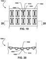
- FIG. 19 and FIG. 20 depict another embodiment of a tolerance ring 1900.
- the tolerance ring 1900 can include a sidewall 1902 formed with a plurality of wave structures 1904 having a generally flat-top pyramid shape.
- the tolerance ring 1900 can include a first plurality of component engagement structures 1906 that can extend from the sidewall 1902 in a direction opposite the wave structures 1904.
- the tolerance ring 1900 can include a second plurality of component engagement structures 1908 and each of the second plurality of component engagement structures 1908 can be formed in a flat distal surface 1910 of a wave structure 1904.
- Each of the second plurality of component engagement structures 1910 can extend in a direction that is opposite the direction of the first plurality of component engagement structures 1906.
- the tolerance ring 2100 can include a sidewall 2102 formed with a plurality of wave structures 2104 having a generally triangular cross-sectional shape.
- the tolerance ring 2100 can include a first plurality of component engagement structures 2106 that can extend from the sidewall 2102 in a direction opposite the wave structures 2104.
- each of the wave structures 2104 can include a distal edge 2108 formed at the apex of two angled surfaces.
- the distal edges 2108 of the wave structures 2104 can act as a second plurality of component engagement structures that extend in a direction that is opposite the direction of the first plurality of component engagement structures 2106.
- the wave structures and the component engagement structures can be evenly space around the circumference of the sidewall wall of the tolerance ring.
- these structures can be staggered so they get progressively closer or progressively farther apart.
- these structures can be grouped and the groups can be evenly spaced around the circumference of the sidewall of the tolerance ring.
- a single tolerance ring can include any combination of the different wave structures and the different component engagement structures. Further, a single tolerance ring can include any number of similar wave structures, any number of different wave structures, any number of similar component engagement structures, any number of different component engagement structures, or any combination thereof. Additionally, a particular tolerance ring can include wave structures facing inward, outward, or inward and outward. Similarly, a particular tolerance ring can include component engagement structures facing inward, outward, or inward and outward.
- a tolerance ring can be made from a metal, a metal alloy, or a combination thereof.
- the metal can include a ferrous metal.
- the metal can include steel.
- the steel can include stainless steel, such as austenitic stainless steel.
- the steel can include stainless steel comprising chrome, nickel, or a combination thereof.
- the steel can X10CrNi18-8 1.4310 stainless steel.
- the tolerance ring can include a Vickers pyramid number hardness, VPN, which can be ⁇ 350, such as ⁇ 375, ⁇ 400, ⁇ 425, or ⁇ 450. VPN can also be ⁇ 500, ⁇ 475, or ⁇ 450.
- the tolerance ring can be treated to increase its corrosion resistance.
- the tolerance ring can be passivated.
- the tolerance ring can be passivated according to the ASTM standard A967.
- the stock material from which the tolerance ring can be formed can have a thickness, T, and T can be ⁇ 0.1 mm, such as ⁇ 0.2 mm, ⁇ 0.3 mm, ⁇ 0.4 mm, ⁇ 0.5 mm, or ⁇ 0.6 mm.
- T can be ⁇ 1.0 mm, ⁇ 0.9 mm, or ⁇ 0.8 mm.
- T can be within a range between, and including, any of the values of T disclosed above.
- the tolerance ring may have an overall outer diameter, OD, and OD can be ⁇ 100 mm, such as ⁇ 110 mm, ⁇ 120 mm, ⁇ 130 mm, ⁇ 140 mm, or ⁇ 150 mm.
- the OD can be ⁇ 300 mm, such as ⁇ 250 mm, or ⁇ 175 mm. Further, OD can be within a range between and including any of the values of OD described herein.
- the tolerance ring can have an overall length, L, and L can be ⁇ 5 mm, ⁇ 10 mm, ⁇ 15 mm, ⁇ 20 mm, or ⁇ 25 mm.
- L can be ⁇ 50 mm, such as ⁇ 45 mm, ⁇ 40 mm, ⁇ 35 mm, or ⁇ 30 mm.
- L can be within a range between, and including, any of the values of L described above.
- a test tolerance ring is manufactured from X10CrNi18-8 1.4310 stainless steel that is 0.6 mm thick and includes a hardness that is between 400-450 VPN.
- the outer diameter of the tolerance ring is approximately 159 mm.
- the tolerance ring has a length of approximately 15 mm.
- Each wave can have a wave pitch of approximately 6.3 mm.
- the tolerance ring includes 2 banks, or rows, of 32 waves with 6 wave blanks opposite the gap.
- Each wave includes a rounded, or radiused profile, and has a length of approximately 1.9 mm.
- the tolerance ring is place around an inner component (i.e., a main frame) that is made from cast iron.
- the inner component has an outer diameter of approximately 158.75 mm ⁇ 0.03 mm and the inner component is approximately 25 mm long.
- the inner component is formed with a groove that has an outer diameter of approximately 156.20 mm ⁇ 0.03 mm.
- the groove has a width of approximately 14.75 mm ⁇ 0.01.
- the assembled tolerance ring/inner component sub-assembly weighs approximately 7.0 kgs.
- An outer component i.e., a housing
- the outer component is made from hot rolled steel plate (SHP-1) and has an outer diameter of approximately 159.37 mm ⁇ 0.1 mm, a wall thickness of approximately 4 mm, and a length of approximately 400 mm.
- the outer component weighs approximately 1.5 kgs.
- the outer component is heated until the outer component expands sufficiently to be placed over the sub-assembly without engaging the sub-assembly. Thereafter, the outer component is cooled, or allowed to cool, to ambient temperature until the outer component returns to an original diameter and the sub-assembly, including the inner component, is secured therein.
- the assembly is oriented so that a longitudinal axis of the assembly is either vertical or at 30° and the assembly is raised to a height of approximately 300 mm measured between a lower end of the assembly and the target surface.
- the assembly is released and allowed to drop vertically onto the target surface and the lower end of the assembly directly contacts the target surface.
- the displacement of the inner component relative to the outer component is less than approximately 0.25 mm.
- a tolerance ring manufactured according to one or more aspects disclosed herein can be fitted around an inner component.
- An outer component can be heated, expanded, and placed over the inner component.
- the inner wall of the outer component can apply a compressive force on a group of wave structures formed on the tolerance ring.
- the compressive force acting on each wave structure can be transmitted to a first plurality of component engagement structures that can be driven, or otherwise forced, into an outer wall of the inner component.
- the tolerance ring can be sufficiently engaged with the inner component and the tolerance ring can prevent the inner component from rotating with respect to the tolerance ring and the outer component with utilizing a welding operation.
- the tolerance ring can also include a second plurality of component engagement structures that extend from the wave structures in a direction opposite the first plurality of engagement structures, e.g., outward.
- each of the second plurality of component engagement structures can extend from a face, or outermost portion, of each wave structure and as the outer component shrinks, each of the second plurality of component engagement structures can be driven, or forced, into and engage an inner wall of the outer component. Accordingly, the tolerance ring can be locked in place between the inner component and the outer component and the inner component can be secured within the outer component.
- first plurality of component engagement structures can sufficiently couple the inner component to the outer component and a welding operation to affix, or attach, the inner component and the outer component to each other can be eliminated.
- a tolerance ring according to one or more aspects described herein and the particular features thereof, e.g., the wave structures and the component engagement structures, can be formed using a stamping operation.
- a flat piece of sheet stock can be placed between a pair of molds having features that are shaped according to the desired features to be stamped into the sheet stock (e.g., the various wave structure shapes and component engagement structure shapes described herein). After stamping, the stamped flat stock can be cut into strips and the strips can be rolled into tolerance rings having a generally cylindrical shape.
Landscapes
- Engineering & Computer Science (AREA)
- General Engineering & Computer Science (AREA)
- Mechanical Engineering (AREA)
- Rolling Contact Bearings (AREA)
- Compressor (AREA)
- Applications Or Details Of Rotary Compressors (AREA)
- Connection Of Plates (AREA)
- Mutual Connection Of Rods And Tubes (AREA)
- Support Of The Bearing (AREA)
- Mounting Of Bearings Or Others (AREA)
Description
- The present disclosure is directed to tolerance rings, particularly to tolerance rings for compressor motors, such as heating, ventilation, air-conditioning (HVAC) compressor motors.
- The present disclosure relates to tolerance ring assemblies, wherein a tolerance ring provides an interference fit between parts of an assembly, in which a first part has a cylindrical portion located in a cylindrical bore of a second part. In particular, the present disclosure relates to assemblies having a tolerance ring that provides an interference fit between a cylindrical component such as a flywheel or a bearing and a housing for the flywheel.
- Improved engineering techniques have resulted in the need for greater accuracy of machine parts, raising manufacturing costs. Very close tolerances are required where press fits, splines, pins or keyways are employed to transmit torque in applications such as pulleys, flywheels, rotors, or drive shafts, or to prevent relative motions between parts, such as stators, main frames, lower frames, and compressor housings.
- Tolerance rings may be used to provide an interference fit between parts required to transmit torque. Tolerance rings provide an efficient means of providing an interference fit between parts that may not be machined to exact dimensions. Tolerance rings have a number of other potential advantages, such as compensating for different linear coefficients of expansion between the parts, allowing rapid apparatus assembly, and durability.
- A tolerance ring generally comprises a strip of resilient material, for example a metal such as spring steel, the ends of which are brought together to form a ring. A band of protrusions extend radially outwards from the ring, or radially inwards towards the center of the ring. Usually, the protrusions are formations, possibly regular formations, such as corrugations, ridges or waves.
- When the ring is located in the annular space between, for example, a shaft and a bore in a housing in which the shaft is located, the protrusions are compressed. Each protrusion acts as a spring and exerts a radial force against the shaft and the surface of the bore, providing an interference fit between the shaft and the housing. Rotation of the housing or the shaft will produce similar rotation in the other of the shaft or the housing, as torque is transmitted by the tolerance ring. Typically, the band of protrusions is axially flanked by annular regions of the ring that have no formations (known in the art as "unformed regions" of the tolerance ring).
DE 295 00 585 U1 relates to a spacer ring for fastening and/or centering at least two components arranged coaxially to one another. - Although tolerance rings usually comprise a strip of resilient material that is curved to allow the easy formation of a ring by overlapping the ends of the strip, a tolerance ring may also be manufactured as an annular band. The term "tolerance ring" as used hereafter includes both types of tolerance ring. The term "shaft" as used hereafter includes any assembly component with a cylindrical portion, such as a shaft, flywheel, stator, rotor, main frame, lower frame, or a bearing.
- Accordingly, the industry continues to need improvements in tolerance rings, particularly tolerance rings installed within compressor motors.
- The present disclosure can be better understood, and its numerous features and advantages made apparent to those skilled in the art by referencing the accompanying drawings.
-
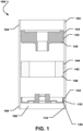
FIG. 1 includes a cross-sectional view of a compressor assembly in accordance with an embodiment. -
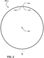
FIG. 2 includes a top plan view of a tolerance ring in accordance with an embodiment. -
FIG. 3 includes a partial side plan view of a tolerance ring in accordance with an embodiment taken atlocation 3 inFIG. 2 . -
FIG. 4 includes a cross-sectional view of a tolerance ring in accordance with an embodiment taken along Line 4-4 inFIG. 3 . -
FIG. 5 includes a partial top plan view of a tolerance ring in accordance with an embodiment installed between an inner component and an outer component. -
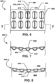
FIG. 6 includes a partial side plan view of a tolerance ring in accordance with another embodiment. -
FIG. 7 includes a cross-sectional view of a tolerance ring in accordance with another embodiment taken along Line 7-7 inFIG. 6 . -
FIG. 8 includes a partial top plan view of a tolerance ring in accordance with another embodiment installed between an inner component and an outer component. -
FIG. 9 includes a partial side plan view of a tolerance ring in accordance with yet another embodiment. -
FIG. 10 includes a cross-sectional view of a tolerance ring in accordance with yet another embodiment taken along Line 10-10 inFIG. 9 . -
FIG. 11 includes a partial side plan view of a tolerance ring in accordance with still another embodiment. -
FIG. 12 includes a cross-sectional view of a tolerance ring in accordance with still another embodiment taken along Line 12-12 inFIG. 11 . -
FIG. 13 includes a partial side plan view of a tolerance ring in accordance with yet still another embodiment. -
FIG. 14 includes a cross-sectional view of a tolerance ring in accordance with yet still another embodiment taken along Line 14-14 inFIG. 13 . -
FIG. 15 includes a partial side plan view of a tolerance ring in accordance with another embodiment. -
FIG. 16 includes a cross-sectional view of a tolerance ring in accordance with another embodiment taken along Line 16-16 inFIG. 15 . -
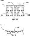
FIG. 17 includes a partial side plan view of a tolerance ring in accordance with yet another embodiment. -
FIG. 18 includes a cross-sectional view of a tolerance ring in accordance with yet another embodiment taken along Line 18-18 inFIG. 17 . -
FIG. 19 includes a partial side plan view of a tolerance ring in accordance with another embodiment. -
FIG. 20 includes a cross-sectional view of a tolerance ring in accordance with another embodiment taken along Line 20-20 inFIG. 19 . -
FIG. 21 includes a partial side plan view of a tolerance ring in accordance with still another embodiment. -
FIG. 22 includes a cross-sectional view of a tolerance ring in accordance with still another embodiment taken along Line 22-22 inFIG. 21 . - The use of the same reference symbols in different drawings indicates similar or identical items.
- The following description is directed to tolerance rings, and particularly, to tolerance rings that can be installed within a compressor assembly between a main frame and a compressor housing, a lower frame and a compressor housing, a stator and a compressor housing, or a combination thereof. In one aspect, a tolerance ring can be fitted around an inner component (e.g., the main frame, the lower frame, the stator, etc.) and then, the compressor housing can be heated and expanded and placed over the inner component. As the compressor housing cools and shrinks, the inner wall of the contracting compressor housing can apply a compressive force on the wave structures of the tolerance ring. The compressive force at each wave structure can be transmitted to a first plurality of component engagement structures.
- Each component engagement structure is located opposite the wave structure. In other words, each component engagement structure is formed on, or extends from, an opposite surface from the wave structure. Further, each component engagement structure is formed in an area that is overlapped the force footprint of the wave structure. The compressive force provided by the shrinking compressor housing can force, or otherwise cause, the component engagement structures to extend into an engage the outer wall of the inner component. Thus, the tolerance ring will be sufficiently engaged with the inner component and the tolerance ring can prevent the inner component from rotating with respect to the tolerance ring.
- The tolerance ring can also include a second plurality of component engagement structures that extend from the wave structures in a direction opposite the first plurality of engagement structures. Specifically, each of the second plurality of component engagement structures can extend from a face of each wave structure and as the outer component shrinks, each of the second plurality of component engagement structures can extend into and engage an inner wall of the outer component. Accordingly, the tolerance ring can be locked in place between the inner component and the outer component. The use of the first plurality of component engagement structures, the second plurality of component engagement structures, or a combination thereof, can sufficiently couple the inner component to the outer component and a welding operation to affix, or attach, the inner component and the outer component to each other can be eliminated.
- Referring initially to
FIG. 1 , a compressor assembly is shown and is generally designated 100. Thecompressor assembly 100 includes acompressor housing 102 that can define aproximal end 104 and adistal end 106. Further, thecompressor housing 102 can include aninternal cavity 108 defined by aninner wall 110 of thecompressor housing 102. A plurality of static compressor components can be installed within thecompressor housing 102 and engaged therewith. - For example, as illustrated, the
compressor assembly 100 can include amain frame 120 disposed within thecompressor housing 102 near theproximal end 104 of thecompressor housing 102. Themain frame 120 can include anouter wall 122. Afirst tolerance ring 124 can be disposed around themain frame 120 and thefirst tolerance ring 124 can engage theouter wall 122 of themain frame 120 and theinner wall 110 of thecompressor housing 102, as described in detail below, in order to securely lock themain frame 120 within thecompressor housing 102. - The
compressor assembly 100 can include alower frame 130 disposed within thecompressor housing 102 near thedistal end 106 of thecompressor housing 102. Thelower frame 130 can include anouter wall 132. Asecond tolerance ring 134 can be disposed around thelower frame 130 and thesecond tolerance ring 134 can engage theouter wall 132 of thelower frame 130 and theinner wall 110 of thecompressor housing 102, as described in detail below, in order to securely lock thelower frame 130 within thecompressor housing 102. - Additionally, the
compressor assembly 100 can include astator 140 disposed within thecompressor housing 102 between themain frame 120 and thelower frame 130. Thestator 140 can include anouter wall 142. Athird tolerance ring 144 can be disposed around thestator 140 and thethird tolerance ring 144 can engage theouter wall 142 of thestator 140 and theinner wall 110 of thecompressor housing 102, as described in detail below, in order to securely lock thestator 140 within thecompressor housing 102. - In a particular aspect, the
main frame 120, thelower frame 130, thestator 140, or a combination thereof, can be formed with a groove in theouter wall respective tolerance ring respective tolerance ring respective tolerance ring - In a particular aspect, during assembly, the
first tolerance ring 124 can be fitted over themain frame 120, thesecond tolerance ring 134 can be fitted over thelower frame 130, and thethird tolerance ring 144 can be fitted over the stator 140 (not necessarily in that order). These sub-assemblies can be properly aligned with, and spaced apart from, each other for further assembly to thecompressor housing 102. - Before, during, or after alignment and placement of the sub-assemblies, the
compressor housing 102 can be heated in order to expand thecompressor housing 102 and the expandedcompressor housing 102 can be placed over the sub-assemblies as illustrated inFIG. 1 . - As the
compressor housing 102 cools and contracts, theinner wall 110 of thecompressor housing 102 can engage thefirst tolerance ring 124, thesecond tolerance ring 134, and thethird tolerance ring 144 and apply a compressive force on thefirst tolerance ring 124, thesecond tolerance ring 134, and thethird tolerance ring 144. The compressive force can cause thefirst tolerance ring 124, or components thereof, to engage themain frame 120, thecompressor housing 102 or a combination thereof. The compressive force can cause thesecond tolerance ring 134, or components thereof, to engage thelower frame 130, thecompressor housing 102 or a combination thereof. Moreover, the compressive force from the cooling and shrinkingcompressor housing 102 can cause thethird tolerance ring 144, or components thereof, to engage thestator 140, thecompressor housing 102 or a combination thereof. - In particular, as described in detail below, a first plurality of component engagement structures on the
first tolerance ring 124 can extend into and engage theouter wall 122 of themain frame 120. Further, a second plurality of component engagement structures on thefirst tolerance ring 124 can extend into and engage theinner wall 110 of thecompressor housing 102. Accordingly, thefirst tolerance ring 124 can lock, or otherwise secure, themain frame 120 to thecompressor housing 102. - Additionally, a first plurality of component engagement structures on the
second tolerance ring 134 can extend into and engage theouter wall 132 of thelower frame 130. A second plurality of component engagement structures on thesecond tolerance ring 134 can extend into and engage theinner wall 110 of thecompressor housing 102. As such, thesecond tolerance ring 134 can lock, or otherwise secure, thelower frame 130 to thecompressor housing 102. - A first plurality of component engagement structures on the
third tolerance ring 144 can extend into and engage theouter wall 142 of thestator 140. Further, a second plurality of component engagement structures on thethird tolerance ring 144 can extend into and engage theinner wall 110 of thecompressor housing 102. Accordingly, thethird tolerance ring 144 can lock, or otherwise secure, thestator 140 to thecompressor housing 102. - Referring now to
FIG. 2 through FIG. 5 , an exemplary tolerance ring is illustrated and is generally designated 200. The tolerance ring 500 depicted inFIG. 2 through FIG. 5 (and any other of the tolerance rings described herein) can be used in thecompressor assembly 100 described above. Further, similar or dissimilar tolerance rings can be used throughout thecompressor assembly 100. - As depicted in
FIG. 2 through FIG. 5 , thetolerance ring 200 can include a generallycylindrical body 202 having a generallycylindrical sidewall 204. Thesidewall 204 can include a top 206 and a bottom 208. Further, thesidewall 204 can include afirst end 210 and asecond end 212. Moreover, agap 214 can be established between thefirst end 210 and thesecond end 212 of thesidewall 204. Thegap 214 can extend completely through thesidewall 204 in order to form a split in thesidewall 204 and thetolerance ring 200. As illustrated inFIG. 2 , thetolerance ring 200 can include acenter 216. -
FIG. 2 through FIG. 5 indicate that thetolerance ring 200 includes a plurality ofwave structures 220 formed in thesidewall 204. Thewave structures 220 can extend outwardly from thesidewall 204 away from thecenter 216 of thetolerance ring 200. Eachwave structure 220 can have a generally hemi-cylindrical body with generally hemi-spherical ends. Further, in plan view as illustrated inFIG. 3 , eachwave structure 220 can be generally oval in shape. - The tolerance ring can include one row of wave structures, two rows of wave structures, three rows of wave structures, etc. Further, a total number of wave structures, NWS, in each row can be ≥ 10, such as ≥ 12, ≥ 14, ≥ 16, ≥ 18, ≥ 20, ≥ 22, ≥ 24, ≥ 26, ≥ 28, ≥ 30, ≥ 32, ≥ 34, ≥ 36, ≥ 38, or ≥ 40. Further, NWS ≤ 200, ≤ 190, ≤ 180, ≤ 170, ≤ 160, ≤ 150, ≤ 140, ≤ 130, ≤ 120, ≤ 110, or ≤ 100. NWS can be within a range between and including any of the NWS values above.
- In another aspect, the
tolerance ring 200 may include a number of wave blanks, i.e., unformed waves, opposite thegap 214 so that thesidewall 204 opposite thegap 214 is unformed and does not include any waves. For example, thetolerance ring 200 may include ≥ 2 unformed waves opposite thegap 214, such as ≥ 2, ≥ 4, ≥ 6, ≥ 8, or ≥ 10. The number of unformed waves opposite thegap 214 can be ≤ 40, such as ≤ 30, or ≤ 20. The number of unformed waves opposite thegap 214 can be within a range between and including any of the values listed in the above paragraph. The wave blanks are centered on an axis that passes through the center of thetolerance ring 216 and bisects thegap 214. - Each
wave structure 220 includes anouter perimeter 222. Further, eachwave structure 220 includes aforce footprint 224 that extends beyond theouter perimeter 222 of thewave structure 220. Theforce footprint 224 is an indication of the area of thetolerance ring 200, e.g., the area of thesidewall 204, over which a force acting perpendicular to thewave structure 220 toward thecenter 216 of thetolerance ring 200 is transmitted. - In a particular aspect, the
force footprint 224 has a perimeter that is similar in shape to theperimeter 222 of thewave structure 220 associated with theforce footprint 224. However, the area, AFF, bound by the perimeter of theforce footprint 224 is ≥ than the area, AWS, of theperimeter 222 bound by theouter perimeter 222 of the wave structure. According to the invention, AFF is ≥ 105% AWS, such as 110% ≥ AWS, 120% ≥ AWS, 130% AWS, 140% AWS, or 150% Aws, and AFF is ≤ 400% AWS, such as ≤ 350% AWS, ≤ 300% AWS, ≤ 250% AWS, or ≤ 200% AWS. AFF is therefore within a range between and including any of the % AWS values above. -
FIG. 3 also indicates that eachwave structure 220 can include a central axis 226. Eachwave structure 220 can be symmetrical about the central axis 226. -
FIG. 2 through FIG. 5 also illustrate that thetolerance ring 200 can include a first plurality ofcomponent engagement structures 230. Each of the first plurality ofcomponent engagement structures 230 can be formed adjacent to theouter perimeter 222 of awave structure 220. Further, each of the first plurality ofcomponent engagement structures 230 can include anouter perimeter 232 and a portion of theouter perimeter 232 of each of the first plurality ofengagement structures 230 can be collinear with theouter perimeter 222 of anadjacent wave structure 220. - For example, a collinearity, C, of the
outer perimeter 232 of eachcomponent engagement structure 230 with theouter perimeter 222 of anadjacent wave structure 220 can be ≥ 10%. As such, at least 10% of theouter perimeter 232 of eachcomponent engagement structure 230 can be collinear with theouter perimeter 222 of theadjacent wave structure 220 and formed along the same linear, curvilinear, or linear/curvilinear line or lines. In another aspect, C, can be ≥ 20%, such as ≥ 25%, ≥ 30%, ≥ 35%, ≥ 45%, or ≥ 50%. Further, C can be ≤ 75%, such as ≤ 70%, ≤ 65%, or ≤ 60%. C can also be within a range between and including any of the values of C described above. - Each of the first plurality of
component engagement structures 230 can include a central axis 234 and the central axis 234 of each of the first plurality ofcomponent engagement structures 230 can be aligned with the central axis 226 of arespective wave structure 220. - As indicated in
FIG. 4 and FIG. 5 , each of the first plurality ofcomponent engagement structures 230 can extend from thesidewall 204 in a direction that is opposite the direction in which thewave structures 220 extend. For example, if thewave structures 220 extend outwardly away from thecenter 216 of thetolerance ring 200, the first plurality ofcomponent engagement structures 230 can extend inwardly toward thecenter 216 of thetolerance ring 200. - As illustrated in
FIG. 4 and FIG. 5 , each of the first plurality ofcomponent engagement structures 230 can have adistal edge 236 that is curved. Specifically, the curvature of eachdistal edge 236 can match the curvature of thesidewall 204. Depending on the orientation of the first plurality ofcomponent engagement structures 230, thedistal edge 236 of each can be an inner edge or an outer edge. - Accordingly, when the
tolerance ring 200 is installed around aninner component 502, such as a stator, a main frame, a lower frame, a shaft, a bearing, etc., and a contractingouter component 504 is placed around thetolerance ring 200, the contractingouter component 504 can provide a compressive force that can act on each of thewave structures 220. The compressive force on eachwave structure 220 can be transmitted to a respectivecomponent engagement structure 230, which is opposite thewave structure 220 and aligned with thewave structure 220, via theforce footprint 224 of thewave structure 220. The force provided by theouter component 504 as theouter component 504 contracts can be great enough to drive the respectivecomponent engagement structure 230, or thedistal edge 236 thereof, at least partially into theinner component 502. Specifically, each of the first plurality ofcomponent engagement structures 230, or the distal edges thereof, can extend at least partially into the outer wall of theinner component 502. - As illustrated in
FIG. 3 , thetolerance ring 200 can include anend feature 238 extending radially from the top 206 of thesidewall 204. Theend feature 238 may be a flange or radial hub extending inward from thesidewall 204 towards thecenter 216 of thetolerance ring 200. Theend feature 238 can be positioned concomitant with a distal end of theinner component 502 to prevent relative axial translation between theinner component 502 and thetolerance ring 200 in a single axial direction. In another aspect, an extra row of thecomponent engagement structures 230 can be positioned along thetolerance ring 200 such that the extra row is concomitant with the distal end of theinner component 502. In other words, the extra row of thecomponent engagement structures 230 may be positioned beyond the distal end of theinner component 502, concomitant with the distal end such that the extra row of thecomponent engagement structures 230 engage the distal end of theinner component 502 and prohibit relative translation of theinner component 502 in a first axial direction. In a further aspect, relative axial translation may be prohibited by an extra row ofwave structures 220 positioned longitudinally concomitant with the distal end of theinner component 502. - As illustrated in
FIG. 2 ,FIG. 4, and FIG. 5 , thewave structures 220 can extend in an outward direction with respect to thecenter 216 of thetolerance ring 200 and thecomponent engagement structures 230 can extend in an inward direction with respect to thecenter 216 of thetolerance ring 200. However, in another aspect, thewave structures 220 can extend in an inward direction toward thecenter 216 of thetolerance ring 200 and thecomponent engagement structures 230 can extend in an outward direction away from thecenter 216 of thetolerance ring 200. - In a particular aspect, each of the plurality of
wave structures 220 includes a depth, DWS, measured from a first face of thesidewall 204 to a distal point on thewave structure 220. The first face of thesidewall 204 can be an outer face of thesidewall 204 and the distal point on thewave structure 220 can be the outer most point of thewave structure 220. Each the first plurality ofcomponent engagement structures 230 includes a depth, DCES1, that can be measured from a second face of thesidewall 204, and DCES1 ≤ DWS to a distal point on thecomponent engagement structure 230. The second face of thesidewall 204 can be an inner face of thesidewall 204 and the distal point on thecomponent engagement structure 230 can be an inner most point on thecomponent engagement structure 230. - According to the invention, DCES1 is ≤ 50% DWS, such as ≤ 45% DWS, ≤ 40% DWS, ≤ 35% DWS, ≤ 30% DWS, or ≤ 25% DWS Further, DCES1 can be ≥ 1% DWS, such as ≥ 2% DWS, ≥ 3% DWS, ≥ 4% DWS, or ≥ 5% DWS. DCES1 can be within a range between and including any of the % of DWS values described herein.
- Further, the
tolerance ring 200 can include an outer diameter, DO, and DCES1 can be ≤ 5%DO, such as ≤ 4%DO, ≤ 3%DO, ≤ 2%DO, or ≤ 1%DO. DCES1 can be ≥ 0.1% DO, such as ≥ 0.2% DO, ≥ 0.3% DO, ≥ 0.4% DO, or ≥ 0.5% DO. Moreover, DCES1 can be within a range between and including any of the % of DO values. - Each of the first plurality of
component engagement structures 230 is at least partially overlapped by theforce footprint 224 of anadjacent wave structure 220. According to the invention, at least a portion of each of the first plurality ofcomponent engagement structures 230 is located within an area bound by the perimeter of theforce footprint 224 of anadjacent wave structure 220. As such, at least a portion of a force acting onparticular wave structure 220 can be transmitted to an adjacent one of the first plurality ofcomponent engagement structures 230 via theforce footprint 224 of thewave structure 220. - In particular, an amount of overlap, O, of each of first plurality of component engages
structures 230 by theforce footprint 224 of anadjacent wave structure 220 can be ≥ 50%, such as ≥ 55%, ≥ 60%, ≥ 65%, ≥ 70%, or ≥ 75%. Further, O can be ≤ 100%, ≤ 99%, ≤ 98%, ≤ 97%, ≤ 96%, ≤ 95%, or ≤ 90%. In another aspect, O can be within a range between and including any of the % values described in this paragraph. O can be the % of an area, or perimeter, of each of the first plurality of component engagement structures that is overlapped. - In another aspect, the
sidewall 204 of thetolerance ring 200 of can have a wall thickness, TW, and DCES1 can be ≤ 200%TW, such as ≤ 175% TW, ≤ 150% TW, ≤ 125% TW, or ≤ 100% TW. Further, DCES1 can be ≥ 25% TW, such as ≥ 50% TW, or ≥ 75% TW. DCES1 can also be within a range between and including any of the % TW values described above. - In yet another aspect, first ratio of a number of
wave structures 220 to a number of firstcomponent engagement structures 230, R1, can be ≥ 0.25:1, such as ≥ 0.5:1, ≥ 0.75:1, or ≥ 1:1. Further, R1 can be ≤ 20:1, ≤ 15:1, ≤ 10:1, ≤ 5:1, ≤ 4:1, ≤ 3:1, or ≤ 2:1. R1 can be within a range between and including any of the R1 values described above. - Referring to
FIG. 6 through FIG. 8 , another embodiment of a tolerance ring is shown and is generally designated 600. Thetolerance ring 600 can include a generallycylindrical body 602 having a generallycylindrical sidewall 604. - As indicated in
FIG. 6 , thetolerance ring 600 can include a plurality ofwave structures 606 that can extend outwardly from thesidewall 604 away from a center of thetolerance ring 600. Thetolerance ring 600 can also include a first plurality ofcomponent engagement structures 608 that can extend inwardly from thesidewall 604 toward a center of thetolerance ring 600. -
FIG. 6 through FIG. 8 further illustrate that thetolerance ring 600 can also include a second plurality ofcomponent engagement structures 610. Each of the second plurality ofcomponent engagement structures 610 can be formed in arespective wave structure 606 and can extend outwardly from thewave structures 606 away from a center of thetolerance ring 600. Each of the second plurality ofcomponent engagement structures 610 can be oriented in a direction parallel to alongitudinal axis 612 of thetolerance ring 600. Further, each of the second plurality ofcomponent engagement structures 610 can have a generally triangular cross-section. - As indicated in
FIG. 6 , eachwave structure 606 can include a central axis 614 and each of the second plurality ofcomponent engagement structures 610 can have a central axis 616. The central axis 614 of eachwave structure 606 and the central axis 616 of each of the second plurality ofcomponent engagement structures 610 can be collinear and can be parallel to thelongitudinal axis 612 of the tolerance ring. - In a particular aspect, each of the plurality of
wave structures 606 can include a depth, DWS, measured from a first face of thesidewall 604. The first face can be an outer face of thesidewall 604. Each of the second plurality ofcomponent engagement structures 610 can include a depth, DCES2, that can be measured from a face, or perimeter, of awave structure 610. DCES2 can be ≤ DWS. Specifically, DCES2 can be ≤ 50% DWS, such as ≤ 45% DWS, ≤ 40% DWS, ≤ 35% DWS, ≤ 30% DWS, or ≤ 25% DWS. Further, DCES2 can be ≥ 1% DWS, such as ≥ 2% DWS, ≥ 3% DWS, ≥ 4% DWS, or ≥ 5% DWS. DCES2 can be within a range between and including any of the % DWS values described herein. - In another aspect, the
tolerance ring 600 can include outer diameter, DO, and DCES2 can be ≤ 5%DO, such as ≤ 4%DO, ≤ 3%DO, ≤ 2%DO, or ≤ 1%DO. Moreover, DCES2 can be ≥ 0.1% DO, such as ≥ 0.2% DO, ≥ 0.3% DO, ≥ 0.4% DO, or ≥ 0.5% DO. DCES2 can be within a range between and including any of the % DO values above. - As illustrated in
FIG. 6 , each of the plurality ofwave structures 606, e.g., the face thereof, can include a length, LWS, and each of the second plurality of component engagement structures can extend at least partially along LWS. Specifically, each of the second plurality ofcomponent engagement structures 606 can extend along at least 10% LWS, such as 15% LWS, 25% LWS, 50% LWS, 75% LWS, 80% LWS, 85% LWS, or 90% LWS. In another aspect, each of the second plurality ofcomponent engagement structures 606 can extend along 100% LWS. - In another aspect, each of the plurality of
wave structures 606, e.g., the face thereof, can include a width, WWS, and wherein each of the second plurality ofcomponent engagement structures 610 can extend at least partially along WWS. In particular, each of the second plurality ofcomponent engagement structures 610 can extend along at least 10% WWS, such as 15% WWS, 25% WWS, 50% WWS, 75% WWS, 80% WWS, 85% WWS, or 90% WWS. Further, each of the second plurality ofcomponent engagement structures 610 can extend along 100% WWS. - In another aspect, the
sidewall 604 of thetolerance ring 600 can includes a wall thickness, TW, and DCES2 can be ≤ 200%TW, such as ≤ 175% TW, ≤ 150% TW, ≤ 125% TW, or ≤ 100% TW. Moreover, DCES2 can be ≥ 25% TW, such as ≥ 50% TW, or ≥ 75% TW. DCES2 can be within a range between and including any of the % TW values described herein. - Each of the second plurality of
component engagement structures 610 can be substantially parallel to thelongitudinal axis 612 of thetolerance ring 600 as illustrated inFIG. 6 . However, each of the second plurality ofcomponent engagement structures 610 can be substantially horizontal to thelongitudinal axis 612 of thetolerance ring 600. In another aspect, each of the second plurality ofcomponent engagement structures 610 can be angle with respect to thelongitudinal axis 612. Moreover, each of the second plurality ofengagement structures 610 can be continuous or discontinuous (i.e., each can include two or more discrete portions). Further, each of the second plurality ofengagement structures 610 can have portions that intersect to form an "X" shape, a "+" shape, or a similar shape. Moreover, each of the second plurality ofengagement structures 610 can be flanked by a pair of the first plurality ofengagement structures 608 extending from thesidewall 604 near each end of arespective wave structure 606. - As illustrated in
FIG. 8 , when thetolerance ring 600 is installed around aninner component 802, such as a stator, a main frame, a lower frame, a shaft, a bearing, etc., and a contractingouter component 804 is placed around thetolerance ring 600, the contractingouter component 804 can provide a compressive force that can act on each of thewave structures 606. The compressive force on eachwave structure 600 can be transmitted to a respective member of the firstcomponent engagement structures 608, as described above. - Each of the first plurality
component engagement structures 608 can extend at least partially into and engage the outer wall of theinner component 802. Further, the compressive force caused by the contractingouter component 804 can cause theouter component 804 to engage the second plurality ofcomponent engagement structures 610 so that each of the second plurality ofcomponent engagement structures 610 extends at least partially into and engages an inner wall of theouter component 804. - In a particular aspect, a second ratio of a number of
wave structures 606 to a number of secondcomponent engagement structures 610, R2, can be ≥ 0.25:1, such as ≥ 0.5:1, ≥ 0.75:1, ≥ 1:1. Further, R2 can be ≤ 20:1, ≤ 15:1, ≤ 10:1, ≤ 5:1, ≤ 4:1, ≤ 3:1, or ≤ 2:1. R2 can be within a range between and including any of the R2 values described above. -
FIG. 9 and FIG. 10 illustrate another embodiment of atolerance ring 900. Thetolerance ring 900 can include asidewall 902 formed with a plurality of generally hemi-spherical wave structures 904. The plurality ofwave structures 904 can extend outwardly from thesidewall 902. Thetolerance ring 900 can also include a first plurality ofcomponent engagement structures 906 that can extend from thesidewall 902 in a direction opposite thewave structures 904, i.e., inwardly from thesidewall 902. - Referring to
FIG. 11 and FIG. 12 , yet another embodiment of a tolerance ring is illustrated and is generally designated 1100. Thetolerance ring 1100 can include asidewall 1102 formed with a plurality of generally hemi-spherical wave structures 1104. The plurality ofwave structures 1104 can extend outwardly from thesidewall 1102. As illustrated, thetolerance ring 1100 can also include a first plurality ofcomponent engagement structures 1106 that can extend from thesidewall 1102 in a direction opposite thewave structures 1104, i.e., inwardly from thesidewall 902. - The
tolerance ring 1100 illustrated inFIG. 11 and FIG. 12 can also include a second plurality ofcomponent engagement structures 1108. Each of the second plurality ofcomponent engagement structures 1108 can be generally cone-shaped and can extend outwardly from arespect wave structure 1104 in a direction opposite the first plurality ofcomponent engagement structures 1106. -
FIG. 13 and FIG. 14 illustrate another embodiment of atolerance ring 1300. Thetolerance ring 1300 can include asidewall 1302 formed with a plurality of generally hemi-cylindrical wave structures 1304 extending from thesidewall 1302. Each of the plurality ofwave structures 1304 can have a roundedsurface 1306 that is flanked by a flatupper surface 1308 and a flatlower surface 1310. Thetolerance ring 1300 can also include a first plurality ofcomponent engagement structures 1312 that can extend from thesidewall 1302 in a direction opposite thewave structures 1304. Each of the first plurality ofcomponent engagement structures 1310 can be formed near an edge of aflat surface longitudinal axis 1314 of thetolerance ring 1300. -
FIG. 15 and FIG. 16 depict yet another embodiment of atolerance ring 1500. Thetolerance ring 1500 can include asidewall 1502 formed with a plurality of generally hemi-cylindrical wave structures 1504 extending from thesidewall 1502. Each of the plurality of wave structures 1504 can have a roundedsurface 1506 that can be flanked by a flatupper surface 1508 and a flatlower surface 1510. Thetolerance ring 1500 can also include a first plurality ofcomponent engagement structures 1512 that can extend from thesidewall 1302 in a direction opposite the wave structures 1504. Thetolerance ring 1500 can also include a second plurality ofcomponent engagement structures 1514 and each can extend from the curvedrounded surface 1506 of a wave structure 1504. The first plurality ofcomponent engagement structures 1512 can be perpendicular to the second plurality ofcomponent engagement structures 1514. - Referring now to
FIG. 17 and FIG. 18 , still another embodiment of atolerance ring 1700 is illustrated. Thetolerance ring 1700 can include asidewall 1702 formed with a plurality ofwave structures 1704 having a generally flat-top pyramid shape. Thetolerance ring 1700 can also include a first plurality ofcomponent engagement structures 1706 that can extend from thesidewall 1702 in a direction opposite thewave structures 1704. Each of the first plurality ofcomponent engagement structures 1706 can be formed near an upper edge or a lower edge of awave structure 1704. Alternatively, each of the first plurality ofcomponent engagement structures 1706 can be formed near a left edge or a right edge of a wave structure. -
FIG. 19 and FIG. 20 depict another embodiment of atolerance ring 1900. Thetolerance ring 1900 can include asidewall 1902 formed with a plurality ofwave structures 1904 having a generally flat-top pyramid shape. Thetolerance ring 1900 can include a first plurality ofcomponent engagement structures 1906 that can extend from thesidewall 1902 in a direction opposite thewave structures 1904. Further, thetolerance ring 1900 can include a second plurality ofcomponent engagement structures 1908 and each of the second plurality ofcomponent engagement structures 1908 can be formed in a flatdistal surface 1910 of awave structure 1904. Each of the second plurality ofcomponent engagement structures 1910 can extend in a direction that is opposite the direction of the first plurality ofcomponent engagement structures 1906. - Referring to
FIG. 21 and FIG. 22 , another embodiment of atolerance ring 2100 is illustrated. Thetolerance ring 2100 can include asidewall 2102 formed with a plurality ofwave structures 2104 having a generally triangular cross-sectional shape. Thetolerance ring 2100 can include a first plurality ofcomponent engagement structures 2106 that can extend from thesidewall 2102 in a direction opposite thewave structures 2104. Further, each of thewave structures 2104 can include adistal edge 2108 formed at the apex of two angled surfaces. Thedistal edges 2108 of thewave structures 2104 can act as a second plurality of component engagement structures that extend in a direction that is opposite the direction of the first plurality ofcomponent engagement structures 2106. - In each of the embodiments described herein, the wave structures and the component engagement structures can be evenly space around the circumference of the sidewall wall of the tolerance ring. However, these structures can be staggered so they get progressively closer or progressively farther apart. Further, these structures can be grouped and the groups can be evenly spaced around the circumference of the sidewall of the tolerance ring.
- Moreover, in other aspects, depending on a particular application, a single tolerance ring can include any combination of the different wave structures and the different component engagement structures. Further, a single tolerance ring can include any number of similar wave structures, any number of different wave structures, any number of similar component engagement structures, any number of different component engagement structures, or any combination thereof. Additionally, a particular tolerance ring can include wave structures facing inward, outward, or inward and outward. Similarly, a particular tolerance ring can include component engagement structures facing inward, outward, or inward and outward.
- In a particular aspect, a tolerance ring according to any of the aspects described herein can be made from a metal, a metal alloy, or a combination thereof. The metal can include a ferrous metal. Further, the metal can include steel. The steel can include stainless steel, such as austenitic stainless steel. Moreover, the steel can include stainless steel comprising chrome, nickel, or a combination thereof. For example, the steel can X10CrNi18-8 1.4310 stainless steel. Further, the tolerance ring can include a Vickers pyramid number hardness, VPN, which can be ≥ 350, such as ≥ 375, ≥ 400, ≥ 425, or ≥ 450. VPN can also be ≤ 500, ≤ 475, or ≤ 450. VPN can also be within a range between, and including, any of the VPN values described herein. In another aspect, the tolerance ring can be treated to increase its corrosion resistance. In particular, the tolerance ring can be passivated. For example, the tolerance ring can be passivated according to the ASTM standard A967.
- In another aspect, the stock material from which the tolerance ring can be formed can have a thickness, T, and T can be ≥ 0.1 mm, such as ≥ 0.2 mm, ≥ 0.3 mm, ≥ 0.4 mm, ≥ 0.5 mm, or ≥ 0.6 mm. In another aspect, T can be ≤ 1.0 mm, ≤ 0.9 mm, or ≤ 0.8 mm. Moreover, T can be within a range between, and including, any of the values of T disclosed above.
- The tolerance ring according to any of the aspects described herein may have an overall outer diameter, OD, and OD can be ≥ 100 mm, such as ≥ 110 mm, ≥ 120 mm, ≥ 130 mm, ≥ 140 mm, or ≥ 150 mm. The OD can be ≤ 300 mm, such as ≤ 250 mm, or ≤ 175 mm. Further, OD can be within a range between and including any of the values of OD described herein.
- In another aspect, the tolerance ring can have an overall length, L, and L can be ≥ 5 mm, ≥ 10 mm, ≥ 15 mm, ≥ 20 mm, or ≥ 25 mm. L can be ≤ 50 mm, such as ≤ 45 mm, ≤ 40 mm, ≤ 35 mm, or ≤ 30 mm. Moreover, L can be within a range between, and including, any of the values of L described above.
- A test tolerance ring is manufactured from X10CrNi18-8 1.4310 stainless steel that is 0.6 mm thick and includes a hardness that is between 400-450 VPN. The outer diameter of the tolerance ring is approximately 159 mm. The tolerance ring has a length of approximately 15 mm. Each wave can have a wave pitch of approximately 6.3 mm. The tolerance ring includes 2 banks, or rows, of 32 waves with 6 wave blanks opposite the gap. Each wave includes a rounded, or radiused profile, and has a length of approximately 1.9 mm.
- The tolerance ring is place around an inner component (i.e., a main frame) that is made from cast iron. The inner component has an outer diameter of approximately 158.75 mm ± 0.03 mm and the inner component is approximately 25 mm long. The inner component is formed with a groove that has an outer diameter of approximately 156.20 mm ± 0.03 mm. The groove has a width of approximately 14.75 mm ± 0.01. The assembled tolerance ring/inner component sub-assembly weighs approximately 7.0 kgs.
- An outer component (i.e., a housing) is provided. The outer component is made from hot rolled steel plate (SHP-1) and has an outer diameter of approximately 159.37 mm ± 0.1 mm, a wall thickness of approximately 4 mm, and a length of approximately 400 mm. The outer component weighs approximately 1.5 kgs.
- The outer component is heated until the outer component expands sufficiently to be placed over the sub-assembly without engaging the sub-assembly. Thereafter, the outer component is cooled, or allowed to cool, to ambient temperature until the outer component returns to an original diameter and the sub-assembly, including the inner component, is secured therein.
- The assembly is oriented so that a longitudinal axis of the assembly is either vertical or at 30° and the assembly is raised to a height of approximately 300 mm measured between a lower end of the assembly and the target surface. The assembly is released and allowed to drop vertically onto the target surface and the lower end of the assembly directly contacts the target surface. The displacement of the inner component relative to the outer component is less than approximately 0.25 mm.
- A tolerance ring manufactured according to one or more aspects disclosed herein can be fitted around an inner component. An outer component can be heated, expanded, and placed over the inner component. As the outer component cools and shrinks, the inner wall of the outer component can apply a compressive force on a group of wave structures formed on the tolerance ring. The compressive force acting on each wave structure can be transmitted to a first plurality of component engagement structures that can be driven, or otherwise forced, into an outer wall of the inner component. Accordingly, the tolerance ring can be sufficiently engaged with the inner component and the tolerance ring can prevent the inner component from rotating with respect to the tolerance ring and the outer component with utilizing a welding operation.
- If a stronger bond between the inner component and our component is needed, the tolerance ring can also include a second plurality of component engagement structures that extend from the wave structures in a direction opposite the first plurality of engagement structures, e.g., outward. In particular, each of the second plurality of component engagement structures can extend from a face, or outermost portion, of each wave structure and as the outer component shrinks, each of the second plurality of component engagement structures can be driven, or forced, into and engage an inner wall of the outer component. Accordingly, the tolerance ring can be locked in place between the inner component and the outer component and the inner component can be secured within the outer component.
- The use of the first plurality of component engagement structures, the second plurality of component engagement structures, or a combination thereof, can sufficiently couple the inner component to the outer component and a welding operation to affix, or attach, the inner component and the outer component to each other can be eliminated.
- In a particular aspect, a tolerance ring according to one or more aspects described herein and the particular features thereof, e.g., the wave structures and the component engagement structures, can be formed using a stamping operation. A flat piece of sheet stock can be placed between a pair of molds having features that are shaped according to the desired features to be stamped into the sheet stock (e.g., the various wave structure shapes and component engagement structure shapes described herein). After stamping, the stamped flat stock can be cut into strips and the strips can be rolled into tolerance rings having a generally cylindrical shape.
- A skilled artisan may recognize other applications that may utilize a tolerance ring having one or more of the characteristics described herein.
Claims (13)
- A tolerance ring (200, 600), comprising:
a generally cylindrical body (202, 602) having a side wall (204, 604) that defines a top (206), and a bottom (208), wherein the side wall (204, 604) includes:a plurality of wave structures (220, 606) extending from the sidewall (204, 604) in a first direction; anda first plurality of component engagement structures (230) extending from the sidewall (204, 604) in a second direction opposite the first direction, wherein each of the first plurality of component engagement structures (230) is configured to at least partially extend into and engage a first component to which the tolerance ring (200, 600) is assembled,each of the plurality of wave structures (220,606) includes a force footprint (224) and wherein each of the first plurality of component engagement structures (230) is at least partially overlapped by the force footprint (224) of an adjacent wave structure (220),wherein the force footprint (224) is an indication of the area of the sidewall (204), over which a force acting perpendicular to the wave structure (220) toward the center (216) of the tolerance ring (200) is transmitted,wherein each component engagement structure (230) is located opposite the wave structure (220), and each wave structure (220) includes a central axis (226) and each of the first plurality of component engagement structures (230) includes a central axis (234) and the central axis (234) of each of the first plurality of component engagement structures (230) is aligned with the central axis (226) of a respective wave structure (220),characterized in that
each of the plurality of wave structures (220) includes a depth, DWS, measured from a first face of the sidewall (204) to a distal point on the wave structure (220), each of the first plurality of component engagement structures (230) includes a depth, DCES1 that is measured from a second face of the sidewall (204) to a distal point on the component engagement structure (230) and DCES1 ≤ 50% Dws,and at least a portion of each of the first plurality of component engagement structures (230) is located within an area bound by the perimeter of the force footprint (224) of an adjacent wave structure (220), wherein the area, AFF, bound by the perimeter of the force footprint (224) is ≥ 105% and ≤ 400% than the area, AWS, of the perimeter (222) bound by the outer perimeter (222) of the wave structure (220). - The tolerance ring (200, 600) of claim 1, wherein DCES1 ≤ 30% DWS.
- The tolerance ring (200, 600) of claim 2, wherein DCES1 ≥ 1% DWS.
- The tolerance ring (200, 600) of claim 1, wherein a first ratio of a number of wave structures (220, 606) to a number of first component engagement structures (230), R1, is ≥ 0.25:1.
- The tolerance ring (200, 600) of claim 3, wherein R1 is ≤ 20:1.
- The tolerance ring (200, 600) of claim 1, further comprising a second plurality of component engagement structures (610) extending from the plurality of wave structures (220, 606), wherein each of the second plurality of component engagement structures (610) is configured to at least partially extend into and engage a second component to which the tolerance ring (200, 600) is assembled.
- The tolerance ring (200, 600) of claim 1, wherein the face of each of the plurality of wave structures (220, 606) includes a length, LWS, and wherein each of the second plurality of component engagement structures (610) extends at least partially along LWS.
- The tolerance ring (200, 600) of claim 5, wherein each of the second plurality of component engagement structures (610) extends along at least 10% LWS.
- The tolerance ring (200, 600) of claim 1, wherein the face of each of the plurality of wave structures (220, 606) includes a width, WWS, and wherein each of the second plurality of component engagement structures (610) extends at least partially along WWS.
- The tolerance ring (200, 600) of claim 7, wherein each of the second plurality of component engagement structures (610) extends along at least 10% WWS.
- The tolerance ring (200, 600) of claim 1, wherein a second ratio of a number of wave structures (220, 606) to a number of second component engagement structures, R2, is ≥ 0.25:1.
- An assembly, comprising:an outer component (504) including a bore within the outer component (504);an inner component (502) disposed within the bore; and a tolerance ring (200, 600), as defined in any one of the previous claims, mounted between the inner component (502) and the outer component (504).
- A compressor (100), comprising:a compressor housing (102) formed with a bore;a static compressor component installed within the bore of the compressor housing (102); anda tolerance ring (200, 600), as defined in any one of claims 1-11, installed around the static compressor component between the static compressor component and the compressor housing (102).
Applications Claiming Priority (2)
| Application Number | Priority Date | Filing Date | Title |
|---|---|---|---|
| US201261666365P | 2012-06-29 | 2012-06-29 | |
| PCT/GB2013/051705 WO2014001810A1 (en) | 2012-06-29 | 2013-06-27 | Tolerance ring with component engagement structures |
Publications (2)
| Publication Number | Publication Date |
|---|---|
| EP2867552A1 EP2867552A1 (en) | 2015-05-06 |
| EP2867552B1 true EP2867552B1 (en) | 2025-04-23 |
Family
ID=48748282
Family Applications (1)
| Application Number | Title | Priority Date | Filing Date |
|---|---|---|---|
| EP13734819.9A Active EP2867552B1 (en) | 2012-06-29 | 2013-06-27 | Tolerance ring with component engagement structures |
Country Status (8)
| Country | Link |
|---|---|
| US (1) | US9062700B2 (en) |
| EP (1) | EP2867552B1 (en) |
| JP (2) | JP2015522771A (en) |
| KR (1) | KR101731257B1 (en) |
| CN (1) | CN104471266B (en) |
| MY (1) | MY171371A (en) |
| TW (1) | TWI525253B (en) |
| WO (1) | WO2014001810A1 (en) |
Families Citing this family (17)
| Publication number | Priority date | Publication date | Assignee | Title |
|---|---|---|---|---|
| JP5474710B2 (en) * | 2010-09-03 | 2014-04-16 | 株式会社東郷製作所 | Torque transmission tolerance ring |
| GB201118597D0 (en) * | 2011-10-27 | 2011-12-07 | Latchways Plc | Fall arrest system safety device |
| JP5781628B2 (en) * | 2011-12-09 | 2015-09-24 | 日本発條株式会社 | Tolerance ring, hard disk device, and method of manufacturing hard disk device |
| WO2014114679A1 (en) * | 2013-01-23 | 2014-07-31 | Saint-Gobain Performance Plastics Rencol Limited | Torque limiting tolerance ring |
| GB2535142B (en) * | 2015-01-28 | 2020-07-29 | Latchways Plc | Energy absorber and fall arrest system safety device |
| WO2016195748A1 (en) * | 2015-05-29 | 2016-12-08 | Bair-Ling Technologies, LLC | Torque-limiting drive train |
| WO2016208477A1 (en) * | 2015-06-23 | 2016-12-29 | オイレス工業株式会社 | Slide bearing |
| JP6605253B2 (en) * | 2015-08-07 | 2019-11-13 | 株式会社東郷製作所 | Tolerance ring |
| NL2016882B1 (en) * | 2016-06-02 | 2018-01-12 | S4 Energy B V | Flywheel systeem |
| US11898608B2 (en) | 2017-04-21 | 2024-02-13 | Saint-Gobain Performance Plastics Rencol Limited | Tolerance ring, method, and assembly for component retention control |
| PL3688330T3 (en) * | 2017-09-29 | 2026-04-20 | Saint-Gobain Performance Plastics Rencol Limited | Tolerance ring |
| JP2021507659A (en) * | 2017-12-15 | 2021-02-22 | サン−ゴバン パフォーマンス プラスティックス レンコール リミティド | Cyclic members, methods, and assemblies for component displacement control |
| JP7280248B2 (en) | 2018-04-24 | 2023-05-23 | 住友化学株式会社 | Amidite compound and method for producing polynucleotide using said compound |
| DE102018215514A1 (en) * | 2018-09-12 | 2020-03-12 | Robert Bosch Gmbh | Compensation element |
| US11211849B2 (en) | 2018-10-31 | 2021-12-28 | Rolls-Royce Corporation | Electric machine with fluid cooled stator assembly |
| JP6899866B2 (en) * | 2019-06-12 | 2021-07-07 | 株式会社オリジン | Tolerance ring |
| WO2021184188A1 (en) * | 2020-03-17 | 2021-09-23 | 元锦生物科技股份有限公司 | Detachable joint structure |
Citations (2)
| Publication number | Priority date | Publication date | Assignee | Title |
|---|---|---|---|---|
| DE29500585U1 (en) * | 1995-01-16 | 1995-03-02 | INA Wälzlager Schaeffler KG, 91074 Herzogenaurach | Spacer ring |
| US20110150375A1 (en) * | 2009-12-18 | 2011-06-23 | Saint-Gobain Performance Plastics Pampus Gmbh | System, method and apparatus for tolerance ring with functional layers |
Family Cites Families (90)
| Publication number | Priority date | Publication date | Assignee | Title |
|---|---|---|---|---|
| US3197243A (en) * | 1961-08-15 | 1965-07-27 | Perfect Circle Corp | Aligning and locking device |
| US3061386A (en) * | 1961-10-04 | 1962-10-30 | Star Kugelhalter Gmbh Dt | Tolerance rings |
| DE1296893B (en) * | 1966-03-25 | 1969-06-04 | Star Kugelhalter Gmbh Dt | Spring band for hub attachment |
| GB1124930A (en) | 1966-05-25 | 1968-08-21 | Chemidus Plastics Ltd | Improvements relating to tubing and piping of thermoplastics material |
| US3423518A (en) | 1966-10-11 | 1969-01-21 | Sigma Ind Inc | Heat shrinkable grommet |
| US3471276A (en) | 1966-11-02 | 1969-10-07 | Du Pont | Peripheral abrasive wheels with composite rims |
| DE1919935C3 (en) | 1969-04-19 | 1978-09-21 | Enka Ag, 5600 Wuppertal | Fixed, heatable stretch or Fixing pin |
| FR2138835B1 (en) | 1971-05-21 | 1973-07-13 | Arctic Pac | |
| IT984360B (en) * | 1972-03-06 | 1974-11-20 | Star Kugelhalter Gmbh Dt | INSERT ELEMENT INTERPOSABLE BETWEEN MACHINE PARTS FOR CONNECTION PURPOSE |
| GB1425465A (en) | 1972-05-04 | 1976-02-18 | Raychem Ltd | Method of making electrical connections |
| US3958311A (en) | 1972-06-06 | 1976-05-25 | Edvard Kusters | Method of making a grooved roller |
| GB1470049A (en) | 1973-03-21 | 1977-04-14 | Rachem Corp | Splicing method and heat-recoverable article |
| GB1421481A (en) | 1973-03-22 | 1976-01-21 | Bruun Sorensen Ltd | Thermally insulated pipe junctions |
| US4039210A (en) | 1976-06-28 | 1977-08-02 | Phillips Petroleum Company | Coupling adapter for plastic pipe |
| JPS58114826A (en) | 1981-12-26 | 1983-07-08 | Kubota Ltd | Shrinkage fitting of ring to journal of hot rolling roll |
| JPS58116036A (en) | 1981-12-29 | 1983-07-11 | Hitachi Ltd | Manufacturing method of rotor of rotating electric machine |
| US4479735A (en) | 1983-01-13 | 1984-10-30 | Westinghouse Electric Corp. | Shrink fit sleeve for rotating machinery |
| JPS59191504A (en) | 1983-04-15 | 1984-10-30 | Hitachi Metals Ltd | Method for fabricating built-up rolling roll |
| JPS59231164A (en) | 1983-06-14 | 1984-12-25 | Suzuki Motor Co Ltd | Cylinder head and manufacture thereof |
| JPS6039363A (en) | 1983-08-11 | 1985-03-01 | Toshiba Corp | Superconductive rotor |
| JPS60128839A (en) | 1983-12-13 | 1985-07-09 | Toshiba Corp | Salient-pole type rotor |
| JPS60190151A (en) | 1984-03-12 | 1985-09-27 | Toshiba Corp | Brushless synchronous machine |
| JPS61132063A (en) | 1984-11-28 | 1986-06-19 | Yaskawa Electric Mfg Co Ltd | Rotor of induction motor |
| US4619373A (en) | 1985-10-04 | 1986-10-28 | Galer Herbert W | Plastic paint container |
| DE3615597A1 (en) | 1986-05-09 | 1987-11-12 | Felten & Guilleaume Energie | Voltage-resistant connecting element for medium-voltage cables |
| DE8624013U1 (en) | 1986-09-08 | 1986-12-18 | Aeg-Elotherm Gmbh, 5630 Remscheid | Electrode head for electrochemical sinking |
| US4981390A (en) * | 1987-03-06 | 1991-01-01 | The Ray Engineering Co., Ltd. | Tolerance ring with retaining means |
| US4828423A (en) * | 1987-04-06 | 1989-05-09 | Cramer Jr Arthur A | Tolerance ring and shim |
| JPH0792066B2 (en) | 1987-04-13 | 1995-10-09 | 松下冷機株式会社 | Rotary compressor |
| DE3816586C2 (en) | 1988-05-16 | 1993-09-30 | Hatz Motoren | Dosing device |
| FR2637260B1 (en) | 1988-09-30 | 1991-04-05 | Cebal | HEAT SHRINK PLUG OR CAPPING CAPSULE FOR MULTIPLE DIAMETERS |
| JPH0315245A (en) | 1989-06-09 | 1991-01-23 | Hitachi Ltd | Rotating electric machine current collector |
| JPH0392610A (en) * | 1989-09-02 | 1991-04-17 | Shizuko Sato | Combining tool for two members |
| GB8926223D0 (en) | 1989-11-20 | 1990-01-10 | Solinst Canada Ltd | Water level probe |
| JP2832388B2 (en) | 1990-04-28 | 1998-12-09 | 日本電産株式会社 | Spindle motor |
| JP2971546B2 (en) | 1990-09-12 | 1999-11-08 | 株式会社東芝 | Commutator device |
| GB2254116B (en) | 1991-03-29 | 1995-01-18 | Rexnord Corp | Shaft seal assemblies |
| JPH0756344B2 (en) | 1991-09-09 | 1995-06-14 | 日本ピラー工業株式会社 | mechanical seal |
| JPH05141591A (en) | 1991-11-13 | 1993-06-08 | Kurimoto Ltd | Joint structure of heat insulated duplex tube |
| JPH07112730A (en) | 1993-10-13 | 1995-05-02 | Toppan Printing Co Ltd | Heat resistant plastic container |
| JPH07132449A (en) * | 1993-11-04 | 1995-05-23 | Mitsubishi Heavy Ind Ltd | Groove machining method |
| US5548458A (en) | 1994-05-04 | 1996-08-20 | Seagate Technology, Inc. | Support flange having electrical contacts to provide electrical continuity upon spindle motor mounting to base |
| US5662362A (en) | 1995-11-13 | 1997-09-02 | Advanced Metal Components, Inc. | Swage coupling including disposable shape memory alloy actuator |
| JPH1023695A (en) | 1996-07-01 | 1998-01-23 | Fuji Electric Co Ltd | Rotating electric machine with radial magnetized rotor |
| JPH10222906A (en) | 1997-02-03 | 1998-08-21 | Nec Corp | Magnetic disk assembly and magnetic disk apparatus using the same |
| JPH10277612A (en) | 1997-04-01 | 1998-10-20 | Japan Steel Works Ltd:The | roll |
| JP2903312B1 (en) | 1998-04-03 | 1999-06-07 | 昭和有機株式会社 | Drop strap for carrying items |
| JP2000241662A (en) | 1999-02-22 | 2000-09-08 | Seiko Instruments Inc | Optical connector and method of manufacturing optical connector |
| JP2000324742A (en) | 1999-05-06 | 2000-11-24 | Hitachi Ltd | Retaining ring for rotating electrical machine, inelastic deformation processing apparatus for retaining ring thereof, and inelastic deformation processing method for retaining ring thereof |
| JP3841601B2 (en) * | 1999-11-19 | 2006-11-01 | 株式会社ジェイテクト | Electric steering device |
| JP2001268875A (en) | 2000-03-16 | 2001-09-28 | Minebea Co Ltd | Spindle motor |
| NL1015724C2 (en) | 2000-07-14 | 2002-01-15 | Skf Eng & Res Centre Bv | Method for assembling a double row angular contact rolling element bearing unit, and unit manufactured according to that method. |
| JP2002130310A (en) * | 2000-10-20 | 2002-05-09 | Nsk Ltd | Unit bearing |
| FR2816199A1 (en) | 2000-11-03 | 2002-05-10 | Carbotech | PROCESS AND SCREENS FOR THE MANUFACTURE OF DENTAL PROSTHESES |
| JP2002249112A (en) | 2001-02-21 | 2002-09-03 | Yazaki Corp | Heat shrinkable film packaging method for bundled electric wire |
| GB0107923D0 (en) | 2001-03-30 | 2001-05-23 | Hansen Transmissions Int | Method for forming a taper roller bearing assembly |
| WO2003025907A1 (en) * | 2001-09-20 | 2003-03-27 | Seagate Technology Llc | Increased slip force pivot bearing |
| US6889956B2 (en) * | 2002-08-16 | 2005-05-10 | Delphi Technologies, Inc. | Poppet valve bushing with tolerance ring |
| JP3817523B2 (en) | 2003-02-14 | 2006-09-06 | 株式会社日立製作所 | Mass spectrometry data analysis system |
| EP1599928B1 (en) | 2003-02-26 | 2013-08-28 | Robert Bosch Gmbh | Electric machine comprising a permanent magnet |
| SE526723C2 (en) | 2003-07-02 | 2005-11-01 | Per Karlsson | Shrink fit ring for securing to electric cable, has central opening with specific reduction in area after shrinking |
| US20050225903A1 (en) * | 2004-04-02 | 2005-10-13 | Sprankle Matthew S | Tolerance ring with debris-reducing profile |
| GB0425856D0 (en) * | 2004-11-24 | 2004-12-29 | Rencol Tolerance Rings Ltd | Fixing of components |
| US7175388B2 (en) | 2005-04-21 | 2007-02-13 | Pratt & Whitney Canada Corp. | Integrated labyrinth and carbon seal |
| US7645116B2 (en) | 2005-04-28 | 2010-01-12 | Ebara Corporation | Turbo vacuum pump |
| DE102005038582B4 (en) | 2005-08-16 | 2007-09-13 | Esa Eppinger Gmbh | Tool clamping insert and tool clamping device |
| US7367763B2 (en) | 2005-12-15 | 2008-05-06 | Kennametal Inc. | Shrink fit tool holder with grooves |
| EP2012025A1 (en) * | 2006-04-27 | 2009-01-07 | NSK Ltd. | Fastening tool, and steering device |
| US8052406B2 (en) * | 2006-11-15 | 2011-11-08 | Emerson Climate Technologies, Inc. | Scroll machine having improved discharge valve assembly |
| EP1961979B1 (en) * | 2007-02-20 | 2013-07-03 | Saint-Gobain Performance Plastics Rencol Limited | Mounting assembly |
| JP5120058B2 (en) | 2007-05-23 | 2013-01-16 | 日本精工株式会社 | State quantity measuring device for rolling bearing unit and manufacturing method thereof |
| JP2009183058A (en) | 2008-01-30 | 2009-08-13 | Asmo Co Ltd | Stator core fixing method and brushless motor |
| JP5193689B2 (en) | 2008-06-06 | 2013-05-08 | 大阪瓦斯株式会社 | Fitting for flexible pipe |
| JP5193690B2 (en) | 2008-06-06 | 2013-05-08 | 大阪瓦斯株式会社 | Fitting for flexible pipe |
| US8684624B2 (en) | 2008-07-01 | 2014-04-01 | Saint-Gobain Performance Plastics Rencol Limited | Tolerance ring |
| JP5157755B2 (en) | 2008-08-29 | 2013-03-06 | 株式会社デンソー | Rotating electric machine stator |
| EP2337962B1 (en) * | 2008-09-10 | 2014-04-16 | Saint-Gobain Performance Plastics Rencol Ltd. | Tolerance ring and mounting assembly with such a tolerance ring |
| CN201257745Y (en) | 2008-09-11 | 2009-06-17 | 浙江众成包装材料有限公司 | Polyolefin thermal contraction film production line |
| JP2010116809A (en) * | 2008-11-12 | 2010-05-27 | Hitachi Automotive Systems Ltd | Pump device |
| JP2010130885A (en) | 2008-12-01 | 2010-06-10 | Mitsubishi Electric Corp | Rotating electric machine |
| WO2010104802A2 (en) | 2009-03-08 | 2010-09-16 | Radyne Corporation | Braze joining of workpieces |
| US20100254758A1 (en) | 2009-04-06 | 2010-10-07 | International Business Machines Corporation | Apparatus and method for forming a mechanical, fluid-tight connection |
| US20110076096A1 (en) * | 2009-09-25 | 2011-03-31 | Saint-Gobain Performance Plastics Rencol Limited | System, method and apparatus for tolerance ring control of slip interface sliding forces |
| JP2011166934A (en) | 2010-02-09 | 2011-08-25 | Toyota Motor Corp | Electric motor |
| JP2011172335A (en) | 2010-02-17 | 2011-09-01 | Toyota Motor Corp | Electric motor |
| JP2011172432A (en) | 2010-02-22 | 2011-09-01 | Ee C Ii Tec Kk | Rotor of embedded magnet synchronous motor |
| CN201674175U (en) | 2010-05-18 | 2010-12-15 | 国核电站运行服务技术有限公司 | Internal eddy current probe cable protection device |
| JP5474710B2 (en) * | 2010-09-03 | 2014-04-16 | 株式会社東郷製作所 | Torque transmission tolerance ring |
| CN101915725B (en) | 2010-09-03 | 2011-12-28 | 中国科学院武汉岩土力学研究所 | Rock core clamping pressure vessel |
| KR101514228B1 (en) * | 2011-03-22 | 2015-04-22 | 생-고뱅 퍼포먼스 플라스틱스 코포레이션 | Bushing with transfigurable electrical conduction state |
-
2013
- 2013-06-25 US US13/926,841 patent/US9062700B2/en active Active
- 2013-06-27 EP EP13734819.9A patent/EP2867552B1/en active Active
- 2013-06-27 MY MYPI2014703763A patent/MY171371A/en unknown
- 2013-06-27 KR KR1020157001247A patent/KR101731257B1/en active Active
- 2013-06-27 WO PCT/GB2013/051705 patent/WO2014001810A1/en not_active Ceased
- 2013-06-27 JP JP2015517863A patent/JP2015522771A/en not_active Ceased
- 2013-06-27 CN CN201380031554.1A patent/CN104471266B/en active Active
- 2013-06-27 TW TW102123066A patent/TWI525253B/en not_active IP Right Cessation
-
2018
- 2018-04-06 JP JP2018074007A patent/JP6626152B2/en active Active
Patent Citations (2)
| Publication number | Priority date | Publication date | Assignee | Title |
|---|---|---|---|---|
| DE29500585U1 (en) * | 1995-01-16 | 1995-03-02 | INA Wälzlager Schaeffler KG, 91074 Herzogenaurach | Spacer ring |
| US20110150375A1 (en) * | 2009-12-18 | 2011-06-23 | Saint-Gobain Performance Plastics Pampus Gmbh | System, method and apparatus for tolerance ring with functional layers |
Also Published As
| Publication number | Publication date |
|---|---|
| JP6626152B2 (en) | 2019-12-25 |
| US20140017105A1 (en) | 2014-01-16 |
| JP2018141559A (en) | 2018-09-13 |
| TWI525253B (en) | 2016-03-11 |
| WO2014001810A1 (en) | 2014-01-03 |
| CN104471266B (en) | 2017-12-15 |
| MY171371A (en) | 2019-10-10 |
| CN104471266A (en) | 2015-03-25 |
| KR101731257B1 (en) | 2017-04-28 |
| EP2867552A1 (en) | 2015-05-06 |
| JP2015522771A (en) | 2015-08-06 |
| US9062700B2 (en) | 2015-06-23 |
| KR20150024408A (en) | 2015-03-06 |
| TW201400703A (en) | 2014-01-01 |
Similar Documents
| Publication | Publication Date | Title |
|---|---|---|
| US9062700B2 (en) | Tolerance ring with component engagement structures | |
| EP3014134B1 (en) | Tolerance ring with divided torque slip | |
| US20240191757A1 (en) | Shaft assembly | |
| EP2932123B1 (en) | Torque limiting tolerance ring | |
| EP2845194B1 (en) | Tolerance ring with perforated waves | |
| EP2845192B1 (en) | Tolerance ring with slotted sidewall | |
| EP2938896B1 (en) | Tolerance ring with discrete tolerance ring panels | |
| EP2867553B1 (en) | Multipiece tolerance ring | |
| US20140205374A1 (en) | Torque Limiting Tolerance Ring | |
| WO2011047483A1 (en) | Permanent magnet rotor assembly provided with welded magnet retaining elements | |
| EP2888150B1 (en) | Shoulderless tolerance ring | |
| US20040058735A1 (en) | Shaft coupling with high torsional elasticity and method of making same | |
| JP3814773B2 (en) | Thrust needle roller bearing cage |
Legal Events
| Date | Code | Title | Description |
|---|---|---|---|
| PUAI | Public reference made under article 153(3) epc to a published international application that has entered the european phase |
Free format text: ORIGINAL CODE: 0009012 |
|
| 17P | Request for examination filed |
Effective date: 20150122 |
|
| AK | Designated contracting states |
Kind code of ref document: A1 Designated state(s): AL AT BE BG CH CY CZ DE DK EE ES FI FR GB GR HR HU IE IS IT LI LT LU LV MC MK MT NL NO PL PT RO RS SE SI SK SM TR |
|
| AX | Request for extension of the european patent |
Extension state: BA ME |
|
| DAX | Request for extension of the european patent (deleted) | ||
| STAA | Information on the status of an ep patent application or granted ep patent |
Free format text: STATUS: EXAMINATION IS IN PROGRESS |
|
| 17Q | First examination report despatched |
Effective date: 20190520 |
|
| RAP3 | Party data changed (applicant data changed or rights of an application transferred) |
Owner name: SAINT-GOBAIN PERFORMANCE PLASTICS RENCOL LIMITED |
|
| GRAP | Despatch of communication of intention to grant a patent |
Free format text: ORIGINAL CODE: EPIDOSNIGR1 |
|
| STAA | Information on the status of an ep patent application or granted ep patent |
Free format text: STATUS: GRANT OF PATENT IS INTENDED |
|
| INTG | Intention to grant announced |
Effective date: 20231127 |
|
| GRAJ | Information related to disapproval of communication of intention to grant by the applicant or resumption of examination proceedings by the epo deleted |
Free format text: ORIGINAL CODE: EPIDOSDIGR1 |
|
| STAA | Information on the status of an ep patent application or granted ep patent |
Free format text: STATUS: EXAMINATION IS IN PROGRESS |
|
| INTC | Intention to grant announced (deleted) | ||
| GRAP | Despatch of communication of intention to grant a patent |
Free format text: ORIGINAL CODE: EPIDOSNIGR1 |
|
| STAA | Information on the status of an ep patent application or granted ep patent |
Free format text: STATUS: GRANT OF PATENT IS INTENDED |
|
| INTG | Intention to grant announced |
Effective date: 20241114 |
|
| GRAS | Grant fee paid |
Free format text: ORIGINAL CODE: EPIDOSNIGR3 |
|
| GRAA | (expected) grant |
Free format text: ORIGINAL CODE: 0009210 |
|
| STAA | Information on the status of an ep patent application or granted ep patent |
Free format text: STATUS: THE PATENT HAS BEEN GRANTED |
|
| AK | Designated contracting states |
Kind code of ref document: B1 Designated state(s): AL AT BE BG CH CY CZ DE DK EE ES FI FR GB GR HR HU IE IS IT LI LT LU LV MC MK MT NL NO PL PT RO RS SE SI SK SM TR |
|
| REG | Reference to a national code |
Ref country code: GB Ref legal event code: FG4D |
|
| REG | Reference to a national code |
Ref country code: CH Ref legal event code: EP |
|
| P01 | Opt-out of the competence of the unified patent court (upc) registered |
Free format text: CASE NUMBER: APP_16002/2025 Effective date: 20250402 |
|
| REG | Reference to a national code |
Ref country code: DE Ref legal event code: R096 Ref document number: 602013086696 Country of ref document: DE |
|
| REG | Reference to a national code |
Ref country code: IE Ref legal event code: FG4D |
|
| PGFP | Annual fee paid to national office [announced via postgrant information from national office to epo] |
Ref country code: DE Payment date: 20250620 Year of fee payment: 13 |
|
| PGFP | Annual fee paid to national office [announced via postgrant information from national office to epo] |
Ref country code: GB Payment date: 20250619 Year of fee payment: 13 |
|
| REG | Reference to a national code |
Ref country code: NL Ref legal event code: MP Effective date: 20250423 |
|
| PG25 | Lapsed in a contracting state [announced via postgrant information from national office to epo] |
Ref country code: NL Free format text: LAPSE BECAUSE OF FAILURE TO SUBMIT A TRANSLATION OF THE DESCRIPTION OR TO PAY THE FEE WITHIN THE PRESCRIBED TIME-LIMIT Effective date: 20250423 |
|
| REG | Reference to a national code |
Ref country code: AT Ref legal event code: MK05 Ref document number: 1788002 Country of ref document: AT Kind code of ref document: T Effective date: 20250423 |
|
| PG25 | Lapsed in a contracting state [announced via postgrant information from national office to epo] |
Ref country code: PT Free format text: LAPSE BECAUSE OF FAILURE TO SUBMIT A TRANSLATION OF THE DESCRIPTION OR TO PAY THE FEE WITHIN THE PRESCRIBED TIME-LIMIT Effective date: 20250825 Ref country code: FI Free format text: LAPSE BECAUSE OF FAILURE TO SUBMIT A TRANSLATION OF THE DESCRIPTION OR TO PAY THE FEE WITHIN THE PRESCRIBED TIME-LIMIT Effective date: 20250423 Ref country code: ES Free format text: LAPSE BECAUSE OF FAILURE TO SUBMIT A TRANSLATION OF THE DESCRIPTION OR TO PAY THE FEE WITHIN THE PRESCRIBED TIME-LIMIT Effective date: 20250423 |
|
| REG | Reference to a national code |
Ref country code: LT Ref legal event code: MG9D |
|
| PG25 | Lapsed in a contracting state [announced via postgrant information from national office to epo] |
Ref country code: GR Free format text: LAPSE BECAUSE OF FAILURE TO SUBMIT A TRANSLATION OF THE DESCRIPTION OR TO PAY THE FEE WITHIN THE PRESCRIBED TIME-LIMIT Effective date: 20250724 Ref country code: NO Free format text: LAPSE BECAUSE OF FAILURE TO SUBMIT A TRANSLATION OF THE DESCRIPTION OR TO PAY THE FEE WITHIN THE PRESCRIBED TIME-LIMIT Effective date: 20250723 |
|
| PG25 | Lapsed in a contracting state [announced via postgrant information from national office to epo] |
Ref country code: PL Free format text: LAPSE BECAUSE OF FAILURE TO SUBMIT A TRANSLATION OF THE DESCRIPTION OR TO PAY THE FEE WITHIN THE PRESCRIBED TIME-LIMIT Effective date: 20250423 |
|
| PG25 | Lapsed in a contracting state [announced via postgrant information from national office to epo] |
Ref country code: BG Free format text: LAPSE BECAUSE OF FAILURE TO SUBMIT A TRANSLATION OF THE DESCRIPTION OR TO PAY THE FEE WITHIN THE PRESCRIBED TIME-LIMIT Effective date: 20250423 |
|
| PG25 | Lapsed in a contracting state [announced via postgrant information from national office to epo] |
Ref country code: HR Free format text: LAPSE BECAUSE OF FAILURE TO SUBMIT A TRANSLATION OF THE DESCRIPTION OR TO PAY THE FEE WITHIN THE PRESCRIBED TIME-LIMIT Effective date: 20250423 |
|
| PG25 | Lapsed in a contracting state [announced via postgrant information from national office to epo] |
Ref country code: AT Free format text: LAPSE BECAUSE OF FAILURE TO SUBMIT A TRANSLATION OF THE DESCRIPTION OR TO PAY THE FEE WITHIN THE PRESCRIBED TIME-LIMIT Effective date: 20250423 |
|
| PGFP | Annual fee paid to national office [announced via postgrant information from national office to epo] |
Ref country code: CH Payment date: 20250701 Year of fee payment: 13 |
|
| PG25 | Lapsed in a contracting state [announced via postgrant information from national office to epo] |
Ref country code: RS Free format text: LAPSE BECAUSE OF FAILURE TO SUBMIT A TRANSLATION OF THE DESCRIPTION OR TO PAY THE FEE WITHIN THE PRESCRIBED TIME-LIMIT Effective date: 20250723 |
|
| PG25 | Lapsed in a contracting state [announced via postgrant information from national office to epo] |
Ref country code: IS Free format text: LAPSE BECAUSE OF FAILURE TO SUBMIT A TRANSLATION OF THE DESCRIPTION OR TO PAY THE FEE WITHIN THE PRESCRIBED TIME-LIMIT Effective date: 20250823 |
|
| PG25 | Lapsed in a contracting state [announced via postgrant information from national office to epo] |
Ref country code: LV Free format text: LAPSE BECAUSE OF FAILURE TO SUBMIT A TRANSLATION OF THE DESCRIPTION OR TO PAY THE FEE WITHIN THE PRESCRIBED TIME-LIMIT Effective date: 20250423 |
|
| PG25 | Lapsed in a contracting state [announced via postgrant information from national office to epo] |
Ref country code: DK Free format text: LAPSE BECAUSE OF FAILURE TO SUBMIT A TRANSLATION OF THE DESCRIPTION OR TO PAY THE FEE WITHIN THE PRESCRIBED TIME-LIMIT Effective date: 20250423 Ref country code: SM Free format text: LAPSE BECAUSE OF FAILURE TO SUBMIT A TRANSLATION OF THE DESCRIPTION OR TO PAY THE FEE WITHIN THE PRESCRIBED TIME-LIMIT Effective date: 20250423 |
|
| PG25 | Lapsed in a contracting state [announced via postgrant information from national office to epo] |
Ref country code: CZ Free format text: LAPSE BECAUSE OF FAILURE TO SUBMIT A TRANSLATION OF THE DESCRIPTION OR TO PAY THE FEE WITHIN THE PRESCRIBED TIME-LIMIT Effective date: 20250423 |
|
| PG25 | Lapsed in a contracting state [announced via postgrant information from national office to epo] |
Ref country code: EE Free format text: LAPSE BECAUSE OF FAILURE TO SUBMIT A TRANSLATION OF THE DESCRIPTION OR TO PAY THE FEE WITHIN THE PRESCRIBED TIME-LIMIT Effective date: 20250423 |
|
| REG | Reference to a national code |
Ref country code: DE Ref legal event code: R097 Ref document number: 602013086696 Country of ref document: DE |
|
| PG25 | Lapsed in a contracting state [announced via postgrant information from national office to epo] |
Ref country code: SK Free format text: LAPSE BECAUSE OF FAILURE TO SUBMIT A TRANSLATION OF THE DESCRIPTION OR TO PAY THE FEE WITHIN THE PRESCRIBED TIME-LIMIT Effective date: 20250423 Ref country code: RO Free format text: LAPSE BECAUSE OF FAILURE TO SUBMIT A TRANSLATION OF THE DESCRIPTION OR TO PAY THE FEE WITHIN THE PRESCRIBED TIME-LIMIT Effective date: 20250423 |
|
| PG25 | Lapsed in a contracting state [announced via postgrant information from national office to epo] |
Ref country code: IT Free format text: LAPSE BECAUSE OF FAILURE TO SUBMIT A TRANSLATION OF THE DESCRIPTION OR TO PAY THE FEE WITHIN THE PRESCRIBED TIME-LIMIT Effective date: 20250423 |
|
| PG25 | Lapsed in a contracting state [announced via postgrant information from national office to epo] |
Ref country code: MC Free format text: LAPSE BECAUSE OF FAILURE TO SUBMIT A TRANSLATION OF THE DESCRIPTION OR TO PAY THE FEE WITHIN THE PRESCRIBED TIME-LIMIT Effective date: 20250423 |
|
| PG25 | Lapsed in a contracting state [announced via postgrant information from national office to epo] |
Ref country code: LU Free format text: LAPSE BECAUSE OF NON-PAYMENT OF DUE FEES Effective date: 20250627 |
|
| REG | Reference to a national code |
Ref country code: BE Ref legal event code: MM Effective date: 20250630 |
|
| PLBE | No opposition filed within time limit |
Free format text: ORIGINAL CODE: 0009261 |
|
| STAA | Information on the status of an ep patent application or granted ep patent |
Free format text: STATUS: NO OPPOSITION FILED WITHIN TIME LIMIT |
|
| REG | Reference to a national code |
Ref country code: CH Ref legal event code: L10 Free format text: ST27 STATUS EVENT CODE: U-0-0-L10-L00 (AS PROVIDED BY THE NATIONAL OFFICE) Effective date: 20260304 |
|
| 26N | No opposition filed |
Effective date: 20260126 |
|
| PG25 | Lapsed in a contracting state [announced via postgrant information from national office to epo] |
Ref country code: IE Free format text: LAPSE BECAUSE OF NON-PAYMENT OF DUE FEES Effective date: 20250627 |
|
| PG25 | Lapsed in a contracting state [announced via postgrant information from national office to epo] |
Ref country code: BE Free format text: LAPSE BECAUSE OF NON-PAYMENT OF DUE FEES Effective date: 20250630 |
|
| PG25 | Lapsed in a contracting state [announced via postgrant information from national office to epo] |
Ref country code: FR Free format text: LAPSE BECAUSE OF NON-PAYMENT OF DUE FEES Effective date: 20250630 |