EP2867445B1 - Cap for submersible pump - Google Patents
Cap for submersible pump Download PDFInfo
- Publication number
- EP2867445B1 EP2867445B1 EP12880168.5A EP12880168A EP2867445B1 EP 2867445 B1 EP2867445 B1 EP 2867445B1 EP 12880168 A EP12880168 A EP 12880168A EP 2867445 B1 EP2867445 B1 EP 2867445B1
- Authority
- EP
- European Patent Office
- Prior art keywords
- cover
- flange
- rubber ring
- collar
- pipe
- Prior art date
- Legal status (The legal status is an assumption and is not a legal conclusion. Google has not performed a legal analysis and makes no representation as to the accuracy of the status listed.)
- Not-in-force
Links
- 238000009434 installation Methods 0.000 claims description 11
- 230000008878 coupling Effects 0.000 claims description 6
- 238000010168 coupling process Methods 0.000 claims description 6
- 238000005859 coupling reaction Methods 0.000 claims description 6
- 239000004033 plastic Substances 0.000 claims description 6
- 239000002184 metal Substances 0.000 claims description 3
- 229910052751 metal Inorganic materials 0.000 claims description 3
- 239000000725 suspension Substances 0.000 description 10
- 238000007789 sealing Methods 0.000 description 9
- 238000006073 displacement reaction Methods 0.000 description 4
- 238000012856 packing Methods 0.000 description 3
- 230000001413 cellular effect Effects 0.000 description 2
- 229910001018 Cast iron Inorganic materials 0.000 description 1
- 230000008030 elimination Effects 0.000 description 1
- 238000003379 elimination reaction Methods 0.000 description 1
- 239000003673 groundwater Substances 0.000 description 1
- 239000000463 material Substances 0.000 description 1
- 230000007246 mechanism Effects 0.000 description 1
- 239000003973 paint Substances 0.000 description 1
- 230000035515 penetration Effects 0.000 description 1
- 238000007665 sagging Methods 0.000 description 1
- XLYOFNOQVPJJNP-UHFFFAOYSA-N water Substances O XLYOFNOQVPJJNP-UHFFFAOYSA-N 0.000 description 1
- 238000003466 welding Methods 0.000 description 1
Images


Classifications
-
- F—MECHANICAL ENGINEERING; LIGHTING; HEATING; WEAPONS; BLASTING
- F04—POSITIVE - DISPLACEMENT MACHINES FOR LIQUIDS; PUMPS FOR LIQUIDS OR ELASTIC FLUIDS
- F04D—NON-POSITIVE-DISPLACEMENT PUMPS
- F04D29/00—Details, component parts, or accessories
- F04D29/08—Sealings
- F04D29/086—Sealings especially adapted for liquid pumps
-
- E—FIXED CONSTRUCTIONS
- E21—EARTH DRILLING; MINING
- E21B—EARTH DRILLING, e.g. DEEP DRILLING; OBTAINING OIL, GAS, WATER, SOLUBLE OR MELTABLE MATERIALS OR A SLURRY OF MINERALS FROM WELLS
- E21B33/00—Sealing or packing boreholes or wells
- E21B33/02—Surface sealing or packing
- E21B33/03—Well heads; Setting-up thereof
- E21B33/04—Casing heads; Suspending casings or tubings in well heads
- E21B33/0407—Casing heads; Suspending casings or tubings in well heads with a suspended electrical cable
-
- F—MECHANICAL ENGINEERING; LIGHTING; HEATING; WEAPONS; BLASTING
- F04—POSITIVE - DISPLACEMENT MACHINES FOR LIQUIDS; PUMPS FOR LIQUIDS OR ELASTIC FLUIDS
- F04D—NON-POSITIVE-DISPLACEMENT PUMPS
- F04D13/00—Pumping installations or systems
- F04D13/02—Units comprising pumps and their driving means
- F04D13/06—Units comprising pumps and their driving means the pump being electrically driven
- F04D13/08—Units comprising pumps and their driving means the pump being electrically driven for submerged use
- F04D13/10—Units comprising pumps and their driving means the pump being electrically driven for submerged use adapted for use in mining bore holes
-
- F—MECHANICAL ENGINEERING; LIGHTING; HEATING; WEAPONS; BLASTING
- F04—POSITIVE - DISPLACEMENT MACHINES FOR LIQUIDS; PUMPS FOR LIQUIDS OR ELASTIC FLUIDS
- F04D—NON-POSITIVE-DISPLACEMENT PUMPS
- F04D29/00—Details, component parts, or accessories
- F04D29/60—Mounting; Assembling; Disassembling
- F04D29/605—Mounting; Assembling; Disassembling specially adapted for liquid pumps
- F04D29/606—Mounting in cavities
- F04D29/607—Mounting in cavities means for positioning from outside
Definitions
- the utility model relates to pipeline equipment for water supply and to oil and gas industry, namely, to auxiliary equipment of submersible pumps.
- the cap is intended for suspension of submersible pump with pressure pipe and cable.
- a known cap for suspension of submersible pump with a pressure pipe and a cable comprising a cover with conical surface and a central axial hole, and a clamping flange with a central axial hole installed on the well casing coaxially, a sealing rubber ring located between the conical surface of the cover and the flange, a set of coupling bolts with nuts installed in the coaxial holes of the cover and the flange ( SU 1 105581 ).
- the shortcoming of the known cap lies in the fact that the sealing rubber ring and the set of coupling bolts with nuts are located on the inner side of the casing pipe, which leads to an increase of the diameter of the casing pipe and a decrease of its effectively used through cross-section.
- the document US 6502632 discloses a head for suspending in a casing pipe 11 a submersible pump 15 with a pressure pipe 14 and a cable 16, containing a cover 18 with a central hole and a circular collar made with a conical inner surface 26, tapered to the central hole, as well as a clamping flange 21 with the central hole, a gasket 20 made of an unknown material (there is no indication that the gasket 20 may be made of rubber, i.e., rubber as a feature is not mentioned in relation to the gasket 20).
- the gasket 20 has a quadrangular trapeziform section (non-round section).
- the gasket 20 is mounted on the casing pipe 11 between the conical surface 26 of the cover's collar 18 and the flat side of the flange 21.
- Clamping screwed elements 22 serve to fix the gasket 20 of trapeziform (non-round) section between the cover and the flange.
- the gasket 20 is made in form of trapeziform section (non-rubber, non-round section)
- the known device is radically different in design and working conditions - the gasket 20 of trapeziform section (non-rubber, non-round section), as compared to a packing assembly with a rubber ring of round section in the claimed device.
- gasket 20 with the pipe 11 contacts along the cylinder surface of the gasket 20, which results in increase of friction in a packing assembly and prevents multiple use of the head.
- the shortcoming of the known device is its low reliability and durability not providing repeated use of the article, which are determined by possible cutting of the edge of the flange hole into the rubber ring and the latter's being insufficiently pressed against the casing pipe.
- a cap for suspension of submersible pump with a pressure pipe and a cable comprising a cover with conical surface and a central axial hole, and a clamping flange with a central axial hole installed on the well casing coaxially.
- a sealing rubber ring located between the conical surface of the cover and the flange, a set of coupling bolts with nuts installed in the coaxial holes of the cover and the flange, where on the butt end of the cover facing the flange, along its circumference, there is a circular collar with inner conical surface, the vertex of its cone facing the side opposite to the flange, while the clamping flange and the sealing rubber ring are installed on the outer side of the casing pipe, where the axial holes in the cover and the flange are also made on the outer side of the casing pipe ( RU 76033 , prototype).
- the shortcoming of the known device is its low reliability and durability not providing repeated use of the article, which are determined by possible cutting of the edge of the flange hole into the rubber ring and the latter's being insufficiently pressed against the casing pipe.
- the engineering target of the claimed utility model is to create an efficient cap for suspension of submersible pump with a pressure pipe and a cable. As well as to expand the range of cap models for suspension of submersible pump with a pressure pipe and a cable.
- the technical result providing solution of the assigned target lies in raising the reliability and durability that provides repeated use of the article determined by eliminating the possibility of cutting of the edge of the flange hole into the rubber ring owing to guaranteed displacement of the edge of the flange hole away from the surface of contact between the flange and the rubber ring, and the latter' s being pressed stronger against the casing pipe owing to making the direction of the ring's pressing against the pipe closer to being radial.
- the cap for suspending the casing of a submersible pump comprising a cover with a central hole and with a circular collar implemented with a conical inner surface narrowing towards the central hole, and a clamping flange with a hole, a rubber ring of round section to be installed onto the casing pipe between the conical surface of the collar of the cover and the flat side of the flange, and coupling threaded elements for fixation of the rubber ring between the cover and the flange, characterized in that the central hole of the clamping flange is made with a diameter smaller than the mean diameter of the rubber ring of round section, while the smaller diameter of the conical surface of the collar of the cover exceeds the mean diameter of the rubber ring.
- the cover and the flange are made of metal, where the flange is made with a cylindrical collar on the side opposite to the side of installation of the rubber ring.
- the cover and the flange are made of plastic, where the flange is made with cylindrical and straight radial stiffening ribs on the side opposite to the side of installation of the rubber ring, and the ring is made with cylindrical and straight radial stiffening ribs on the side of installation of the rubber ring.
- the cover is provided with a collet clamp for the pressure pipe of the pump, the aforesaid collet clamp installed in the central axial hole of the cover, the cover is provided with at least one cable entry, the cover is provided with upper and lower eyebolts.
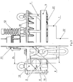
- the Fig. 1 presents a general exploded view of a well cap for suspension of submersible pump with a pressure pipe and a cable
- Fig.2 presents a cutaway view of installation of the cap onto a casing pipe
- Fig.3 presents a cutaway view of installation of a plastic cap onto a casing pipe.
- the well cap for suspension of submersible pump with a pressure pipe and a cable comprises cover 2 with central axial hole 4 for passage of pressure pipe 22 and with circular collar 10 made with cylindrical outer surface and conical inner surface 3 narrowing towards central hole 4, as well as cylindrical flange 5 with central hole 17, sealing rubber ring 6 of round section to be installed onto casing pipe 1 between conical surface 3 of collar 10 of cover 2 and flat side 18 of flange 5.
- the coupling threaded elements - bolts 7 with nuts 8 are installed in coaxial holes 9 of cover 2 and flange 5 for fixation of rubber ring 6 with its inner diameter on outer surface of pipe 1 between cover 2 and flange 5.
- Central hole 1 7 of clamping flange 5 is made with diameter D 1 smaller than mean diameter Dcp rubber ring 6, while smaller diameter D 2 of conical surface 3 of collar 10 of cover 2, exceeding mean diameter Dcp, which is equal to the half sum of the outer and inner diameters of rubber ring 6.
- Cover 2 is provided with collet clamp 11 for pressure pipe 22, the aforesaid collet clamp installed in central axial hole 4 of cover 2. Cover 2 is also provided with cable entry 12.
- cover 2 and flange 5 may be made of metal (cast iron), where flange 5 is made with cylindrical collar 19 on the side opposite to the side of installation of rubber ring 6, while hole 4 is made a thread for collet clamp 11 .
- cover 2 and flange 5 may be made of plastic.
- collet clamp 11 may be made partially (with its fixed part) integral with cover 2, where hole 4 (for pipe 22) of cover 2 is at the same time a hole of the fixed part of collet clamp 1 1 made integral therewith.
- flange 5 is made of cellular design, i.e., with cylindrical and straight stiffening ribs 21 on the side opposite to the side of installation of rubber ring 6, while cover 2 is also made of cellular design, i.e., with cylindrical and straight radial stiffening ribs 20 around collar 10, on the side of installation of rubber ring 6.
- cover 2 is provided with upper eyebolts 13 and lower eyebolt 14 with sealing cap locknut 15 and suspended clevis 16 for fastening of a rope for suspension of submersible pump (not shown). All eyebolts 13, 14 are located in the same centerline plane, where the vertical axis of the cover and the flange lies.
- Coaxial holes 9 in cover 2 and flange 5 are made around collar 10 and, hence, on the outer side of casing pipe 1.
- the well cap for suspension of submersible pump with a pressure pipe and a cable is operated as follows.
- Hermetic sealing of the pump in pipe 1 is achieved through tightening of bolts 7 contracting sealing rubber ring 6, which is located between cover 2 and clamping flange 5.
- the pipe is tightening and clamped with collet clamp 11.
- assembling requires no welding operations; the pump is lowered with a winch, crane, or other hoisting mechanisms by upper eyebolts 1 3 mounted in cover 2.
- central hole 17 of clamping flange 5 is made with diameter D 1 , which is guaranteed to be smaller than mean diameter Dcp rubber ring 6, the possibility for the edge of hole 17 of flange 5 into rubber ring 6 is eliminated owing to guaranteed displacement of the edge of hole 17 of flange 5 to pipe 1 from the surface of contact of flange 5 with rubber ring 6 and a larger area of the latter' s contact with side 1 8 of flange 5.
- this structure safely prevents the pipe and the submersible pump from penetration of surface ground waters and foreign objects, protects the pump and the pipe from unauthorized access, increases reliability and durability of the article, and provides repeated use of the rubber ring.
- the present invention is embodied with multipurpose equipment extensively applied in the industry.
Description
- The utility model relates to pipeline equipment for water supply and to oil and gas industry, namely, to auxiliary equipment of submersible pumps. The cap is intended for suspension of submersible pump with pressure pipe and cable.
- There is a known cap for suspension of submersible pump with a pressure pipe and a cable comprising a cover with conical surface and a central axial hole, and a clamping flange with a central axial hole installed on the well casing coaxially, a sealing rubber ring located between the conical surface of the cover and the flange, a set of coupling bolts with nuts installed in the coaxial holes of the cover and the flange (
SU 1 105581 - The shortcoming of the known cap lies in the fact that the sealing rubber ring and the set of coupling bolts with nuts are located on the inner side of the casing pipe, which leads to an increase of the diameter of the casing pipe and a decrease of its effectively used through cross-section.
- There is a known cap for suspension of submersible pump with a pressure pipe and a cable (
US 6502632 ). - The document
US 6502632 discloses a head for suspending in a casing pipe 11 asubmersible pump 15 with apressure pipe 14 and acable 16, containing acover 18 with a central hole and a circular collar made with a conical inner surface 26, tapered to the central hole, as well as aclamping flange 21 with the central hole, agasket 20 made of an unknown material (there is no indication that thegasket 20 may be made of rubber, i.e., rubber as a feature is not mentioned in relation to the gasket 20). In the document, thegasket 20 has a quadrangular trapeziform section (non-round section). Thegasket 20 is mounted on thecasing pipe 11 between the conical surface 26 of the cover'scollar 18 and the flat side of theflange 21. Clamping screwedelements 22 serve to fix thegasket 20 of trapeziform (non-round) section between the cover and the flange. - Basing on drawings of the document
US 6502632 it can be assumed only that the central hole of theclamping flange 21 has a diameter smaller than the mean diameter of thegasket 20 of trapeziform section. It is impossible to state that the minor diameter of the conical surface 26 of the cover'scollar 18 exceeds the mean diameter of thegasket 20 of trapeziform section, which is equal to half-sum of outer and inner diameters of thegasket 20. - At that in the source of information
US 6502632 it is impossible to use features of the claimed invention, related to accomplishment of a packing assembly of the device and to obtain a corresponding technical result through its use. Taking into account that in the source of informationUS 6502632 thegasket 20 is made in form of trapeziform section (non-rubber, non-round section), the known device is radically different in design and working conditions - thegasket 20 of trapeziform section (non-rubber, non-round section), as compared to a packing assembly with a rubber ring of round section in the claimed device. - In this known device there may not be excluded the possible cutting of the
flange 21 hole edge in thegasket 20, made in form of trapeziform section (non-rubber, non-round section), and there is no displacement of theflange 21 hole edge from theflange 21 contact surface with thegasket 20, made in form of trapeziform section (non-rubber, non-round section) - In addition, the
gasket 20 with thepipe 11 contacts along the cylinder surface of thegasket 20, which results in increase of friction in a packing assembly and prevents multiple use of the head. - The shortcoming of the known device is its low reliability and durability not providing repeated use of the article, which are determined by possible cutting of the edge of the flange hole into the rubber ring and the latter's being insufficiently pressed against the casing pipe.
- Also known is a cap for suspension of submersible pump with a pressure pipe and a cable comprising a cover with conical surface and a central axial hole, and a clamping flange with a central axial hole installed on the well casing coaxially. a sealing rubber ring located between the conical surface of the cover and the flange, a set of coupling bolts with nuts installed in the coaxial holes of the cover and the flange, where on the butt end of the cover facing the flange, along its circumference, there is a circular collar with inner conical surface, the vertex of its cone facing the side opposite to the flange, while the clamping flange and the sealing rubber ring are installed on the outer side of the casing pipe, where the axial holes in the cover and the flange are also made on the outer side of the casing pipe (
RU 76033 - The shortcoming of the known device is its low reliability and durability not providing repeated use of the article, which are determined by possible cutting of the edge of the flange hole into the rubber ring and the latter's being insufficiently pressed against the casing pipe.
- The engineering target of the claimed utility model is to create an efficient cap for suspension of submersible pump with a pressure pipe and a cable. As well as to expand the range of cap models for suspension of submersible pump with a pressure pipe and a cable.
- The technical result providing solution of the assigned target lies in raising the reliability and durability that provides repeated use of the article determined by eliminating the possibility of cutting of the edge of the flange hole into the rubber ring owing to guaranteed displacement of the edge of the flange hole away from the surface of contact between the flange and the rubber ring, and the latter' s being pressed stronger against the casing pipe owing to making the direction of the ring's pressing against the pipe closer to being radial.
- The essence of the invention is that the cap for suspending the casing of a submersible pump, comprising a cover with a central hole and with a circular collar implemented with a conical inner surface narrowing towards the central hole, and a clamping flange with a hole, a rubber ring of round section to be installed onto the casing pipe between the conical surface of the collar of the cover and the flat side of the flange, and coupling threaded elements for fixation of the rubber ring between the cover and the flange, characterized in that the central hole of the clamping flange is made with a diameter smaller than the mean diameter of the rubber ring of round section, while the smaller diameter of the conical surface of the collar of the cover exceeds the mean diameter of the rubber ring.
- In particular embodiments, the cover and the flange are made of metal, where the flange is made with a cylindrical collar on the side opposite to the side of installation of the rubber ring.
- In other particular embodiments, the cover and the flange are made of plastic, where the flange is made with cylindrical and straight radial stiffening ribs on the side opposite to the side of installation of the rubber ring, and the ring is made with cylindrical and straight radial stiffening ribs on the side of installation of the rubber ring.
- Preferably, the cover is provided with a collet clamp for the pressure pipe of the pump, the aforesaid collet clamp installed in the central axial hole of the cover, the cover is provided with at least one cable entry, the cover is provided with upper and lower eyebolts.
- The
Fig. 1 presents a general exploded view of a well cap for suspension of submersible pump with a pressure pipe and a cable,Fig.2 presents a cutaway view of installation of the cap onto a casing pipe, andFig.3 presents a cutaway view of installation of a plastic cap onto a casing pipe. - The well cap for suspension of submersible pump with a pressure pipe and a cable comprises
cover 2 with centralaxial hole 4 for passage ofpressure pipe 22 and withcircular collar 10 made with cylindrical outer surface and conicalinner surface 3 narrowing towardscentral hole 4, as well ascylindrical flange 5 withcentral hole 17, sealingrubber ring 6 of round section to be installed onto casing pipe 1 betweenconical surface 3 ofcollar 10 ofcover 2 andflat side 18 offlange 5. The coupling threaded elements -bolts 7 withnuts 8 are installed incoaxial holes 9 ofcover 2 andflange 5 for fixation ofrubber ring 6 with its inner diameter on outer surface of pipe 1 betweencover 2 andflange 5. Central hole 1 7 ofclamping flange 5 is made with diameter D1 smaller than mean diameterDcp rubber ring 6, while smaller diameter D2 ofconical surface 3 ofcollar 10 ofcover 2, exceeding mean diameter Dcp, which is equal to the half sum of the outer and inner diameters ofrubber ring 6. -
Cover 2 is provided withcollet clamp 11 forpressure pipe 22, the aforesaid collet clamp installed in centralaxial hole 4 ofcover 2.Cover 2 is also provided withcable entry 12. - In particular embodiments,
cover 2 andflange 5 may be made of metal (cast iron), whereflange 5 is made withcylindrical collar 19 on the side opposite to the side of installation ofrubber ring 6, whilehole 4 is made a thread forcollet clamp 11 . - In other particular embodiments,
cover 2 andflange 5 may be made of plastic. In this case,collet clamp 11 may be made partially (with its fixed part) integral withcover 2, where hole 4 (for pipe 22) ofcover 2 is at the same time a hole of the fixed part of collet clamp 1 1 made integral therewith. Here,flange 5 is made of cellular design, i.e., with cylindrical and straightstiffening ribs 21 on the side opposite to the side of installation ofrubber ring 6, whilecover 2 is also made of cellular design, i.e., with cylindrical and straight radialstiffening ribs 20 aroundcollar 10, on the side of installation ofrubber ring 6. - In any case,
cover 2 is provided withupper eyebolts 13 andlower eyebolt 14 with sealing cap locknut 15 and suspendedclevis 16 for fastening of a rope for suspension of submersible pump (not shown). Alleyebolts -
Coaxial holes 9 incover 2 andflange 5 are made aroundcollar 10 and, hence, on the outer side of casing pipe 1. - The well cap for suspension of submersible pump with a pressure pipe and a cable is operated as follows.
- For putting in operation, prior to suspending a submersible pump with a pressure pipe and a cable, it is necessary to cut casing pipe thoroughly at right angle to its axis, which is rather difficult to do in field conditions. Then burrs are removed at the cut, casing pipe 1 is trimmed up from outside, primed and coated with corrosion-proof paint. The submersible pump is prepared for submersion according the pump manual, which includes connecting plastic pipe to the pump fitting, attaching a rope of required length to the pump housing and extending the control cable.
- Next, the free part of the rope is attached to
clevis 16.Clevis 16 is engaged withlower eyebolt 14, after the plastic pressure pipe has been threaded throughcollet clamp 11, and the cables have been threaded throughcable entries 12 ofcover 2.Flange 5 is put, with its flat side (surface) 18 upwards, jointly withrubber ring 6, onto casing pipe 1. The pipe is lowered, whereuponcover 2 is put onto casing pipe 1. Then,rubber ring 6 andflange 5 are raised up to the contact ofring 6 withconical surface 3 ofcover 2.Bolts 7 andnuts 8 are used for drawing togetherflange 5 and cover 2, while contractingrubber ring 6 placed in-between. - Hermetic sealing of the pump in pipe 1 is achieved through tightening of
bolts 7 contracting sealingrubber ring 6, which is located betweencover 2 and clampingflange 5.Conical surface 3, when clamped withbolts 7 ofcover 2 withflange 5, exercises clamping ofrubber ring 6 around pipe 1. To prevent the pressure pipe of the pump from sagging, the pipe is tightening and clamped withcollet clamp 11. At the same time, assembling requires no welding operations; the pump is lowered with a winch, crane, or other hoisting mechanisms by upper eyebolts 1 3 mounted incover 2. - As
central hole 17 ofclamping flange 5 is made with diameter D1, which is guaranteed to be smaller than mean diameterDcp rubber ring 6, the possibility for the edge ofhole 17 offlange 5 intorubber ring 6 is eliminated owing to guaranteed displacement of the edge ofhole 17 offlange 5 to pipe 1 from the surface of contact offlange 5 withrubber ring 6 and a larger area of the latter' s contact with side 1 8 offlange 5. - As smaller diameter D2 of
conical surface 3 of collar 1 0 ofcover 2 is guaranteed to be made exceeding mean diameterDcp rubber ring 6, the force pressing the latter against pipe 1 is guaranteed to increase owing to the fact that the direction of the ring's being pressed against pipe 1 is made closer to being radial and hence, the component normal to surfaces of pipe 1 , ofring 6 of round section is increased, as well as the area of contact of the same that provides hermetic sealing and reliability of the joint. At the same time increased reliability and durability are provided that is determined by elimination of the possibility for the edge of the flange to cut inlo the rubber ring owing to guaranteed displacement of the edge of the flange hole from the surface of contact of the flange with the rubber ring. - According to its designated purpose, this structure safely prevents the pipe and the submersible pump from penetration of surface ground waters and foreign objects, protects the pump and the pipe from unauthorized access, increases reliability and durability of the article, and provides repeated use of the rubber ring.
- The present invention is embodied with multipurpose equipment extensively applied in the industry.
Claims (6)
- A cap for suspending the casing of a submersible pump, comprising a cover (2) with a central hole (4) and with a circular collar (10) implemented with a conical inner surface (3) narrowing towards the central hole (4), and a clamping flange (5) with a hole (17), a rubber ring (6) of round section to be installed onto a casing pipe 1 between the conical surface (3) of the collar (10) of the cover (2) and the flat side (18) of the flange (5), and coupling threaded elements (7) for fixation of the rubber ring (6) between the cover (2) and the flange (5), characterized in that the central hole (17) of the clamping flange (5) is made with a diameter (D1) smaller than the mean diameter (Dcp)of the rubber ring (6) of round section, while the smaller diameter (D2) of the conical surface (3) of the collar (10) of the cover (2) exceeds the mean diameter (Dcp) of the rubber ring (6).
- The cap according to Claim 1, characterized in that the cover (2) and the flange (5) are made of metal, where the flange is made with a cylindrical collar (12) on the side opposite to the side of installation of the rubber ring (6).
- The cap according to Claim 1, characterized in that the cover (2) and the flange (5) are made of plastic, where the flange (5) is made with cylindrical and straight radial stiffening ribs (21) on the side opposite to the side of installation of the rubber ring (6), while the cover (2) is made with cylindrical and radial stiffening ribs (20) on the side of installation of the rubber ring (6).
- The cap according to any one of Claims 1-3, characterized in that the cover (2) has a collet clamp (11) installed in its central axial hole (4) for the pressure pipe (22) of the pump.
- The cap according to any one of Claims 1-3, characterized in that the cover (2) is provided with at least one cable entry (12).
- The cap according to any one of Claims 1-3, characterized in that the cover (2) is provided with upper eyebolts (13) and a lower eyebolt (14).
Applications Claiming Priority (2)
| Application Number | Priority Date | Filing Date | Title |
|---|---|---|---|
| RU2012127091 | 2012-06-28 | ||
| PCT/RU2012/000718 WO2014003601A1 (en) | 2012-06-28 | 2012-08-30 | Cap for submersible pump |
Publications (3)
| Publication Number | Publication Date |
|---|---|
| EP2867445A1 EP2867445A1 (en) | 2015-05-06 |
| EP2867445A4 EP2867445A4 (en) | 2016-03-09 |
| EP2867445B1 true EP2867445B1 (en) | 2017-04-26 |
Family
ID=49783590
Family Applications (1)
| Application Number | Title | Priority Date | Filing Date |
|---|---|---|---|
| EP12880168.5A Not-in-force EP2867445B1 (en) | 2012-06-28 | 2012-08-30 | Cap for submersible pump |
Country Status (10)
| Country | Link |
|---|---|
| US (1) | US9885363B2 (en) |
| EP (1) | EP2867445B1 (en) |
| JP (1) | JP3198337U (en) |
| CN (1) | CN204677151U (en) |
| BR (1) | BR212014032679U2 (en) |
| EA (1) | EA027361B1 (en) |
| RU (1) | RU2015102731A (en) |
| UA (1) | UA99628U (en) |
| WO (1) | WO2014003601A1 (en) |
| ZA (1) | ZA201500585B (en) |
Families Citing this family (5)
| Publication number | Priority date | Publication date | Assignee | Title |
|---|---|---|---|---|
| EP3421716B1 (en) * | 2017-06-26 | 2020-06-24 | Grundfos Holding A/S | Submersible downhole pump |
| CN108204379B (en) * | 2018-01-10 | 2019-10-29 | 江苏绩优机电科技有限公司 | Submerged axial-flow propeller pump cable suspension system |
| CZ34754U1 (en) * | 2020-10-30 | 2021-01-12 | Petr Havránek | Borehole termination equipment |
| CN112377141B (en) * | 2020-12-08 | 2022-11-11 | 重庆前卫科技集团有限公司 | Spare locking device for oil pipe hanger of underwater Christmas tree |
| RU209735U1 (en) * | 2021-08-09 | 2022-03-22 | Федеральное государственное бюджетное образовательное учреждение высшего образования "Камчатский государственный технический университет" | HEAD OF THE OBSERVATION WELL |
Family Cites Families (11)
| Publication number | Priority date | Publication date | Assignee | Title |
|---|---|---|---|---|
| US1509643A (en) * | 1923-04-20 | 1924-09-23 | Forsberg L Albin | Well cap |
| US2390393A (en) * | 1944-03-22 | 1945-12-04 | Rubly William | Well casing cap |
| US2443187A (en) * | 1944-08-15 | 1948-06-15 | James C Hobbs | Pipe coupling |
| SU595485A1 (en) * | 1975-12-25 | 1978-02-28 | Татарский научно-исследовательский и проектно-конструкторский институт нефтяного машиностроения | Tubular cap for sealing head of submersible pump boreholes |
| DE3013757A1 (en) * | 1980-04-10 | 1981-10-15 | Stiebel Eltron Gmbh & Co Kg, 3450 Holzminden | Cylindrical plastics water tank - has internal stiffening ribs wrapped in glass-fibre at domed end regions |
| US5943836A (en) * | 1998-09-10 | 1999-08-31 | Don De Cristo Concrete Accessories, Inc. | Protective cover for concrete reinforcing bar |
| US6502632B1 (en) * | 2001-03-27 | 2003-01-07 | James R. Pittman | Well cap apparatus |
| US7231968B2 (en) * | 2003-02-28 | 2007-06-19 | Eric Owens | Well cap systems |
| RU2254440C1 (en) * | 2003-11-17 | 2005-06-20 | Общество с ограниченной ответственностью "ТюменНИИгипрогаз" | Column head for well mouth pressurization |
| GB0502298D0 (en) * | 2005-02-04 | 2005-03-16 | Petrowell Ltd | Well assembly and method |
| RU76033U1 (en) * | 2008-05-07 | 2008-09-10 | "Торговый Дом Джилекс" | BORE HEAD |
-
2012
- 2012-08-30 EA EA201401295A patent/EA027361B1/en unknown
- 2012-08-30 US US14/411,205 patent/US9885363B2/en not_active Expired - Fee Related
- 2012-08-30 JP JP2015600046U patent/JP3198337U/en not_active Expired - Lifetime
- 2012-08-30 EP EP12880168.5A patent/EP2867445B1/en not_active Not-in-force
- 2012-08-30 RU RU2015102731A patent/RU2015102731A/en unknown
- 2012-08-30 CN CN201290001267.7U patent/CN204677151U/en not_active Expired - Lifetime
- 2012-08-30 WO PCT/RU2012/000718 patent/WO2014003601A1/en active Application Filing
- 2012-08-30 UA UAU201500632U patent/UA99628U/en unknown
- 2012-08-30 BR BR212014032679U patent/BR212014032679U2/en not_active IP Right Cessation
-
2015
- 2015-01-26 ZA ZA2015/00585A patent/ZA201500585B/en unknown
Also Published As
| Publication number | Publication date |
|---|---|
| WO2014003601A1 (en) | 2014-01-03 |
| EA027361B1 (en) | 2017-07-31 |
| US20150198171A1 (en) | 2015-07-16 |
| JP3198337U (en) | 2015-07-02 |
| CN204677151U (en) | 2015-09-30 |
| BR212014032679U2 (en) | 2019-09-24 |
| RU2015102731A (en) | 2016-08-20 |
| EP2867445A1 (en) | 2015-05-06 |
| UA99628U (en) | 2015-06-10 |
| ZA201500585B (en) | 2016-01-27 |
| US9885363B2 (en) | 2018-02-06 |
| EP2867445A4 (en) | 2016-03-09 |
| EA201401295A1 (en) | 2015-04-30 |
Similar Documents
| Publication | Publication Date | Title |
|---|---|---|
| EP2867445B1 (en) | Cap for submersible pump | |
| US8544912B1 (en) | Lifting sling assembly | |
| KR102162670B1 (en) | Pipe connecting device for piping | |
| CN204956855U (en) | Protective barrier | |
| KR100989052B1 (en) | Pipe connecting apparatus | |
| JP5477861B2 (en) | Jig for assembly / disassembly of annular parts | |
| RU145375U1 (en) | BORE HEAD | |
| RU76033U1 (en) | BORE HEAD | |
| RU122141U1 (en) | SUBMERSIBLE PUMP HEAD | |
| RU164593U1 (en) | WELL HEAD | |
| CN108087657A (en) | A kind of sea-bottom oil-gas pipeline fixture | |
| KR101544104B1 (en) | Underground Cable Distribution Grounding Device for Low Voltage Cabling Box | |
| CN104065010A (en) | Marine shore cable threading structure | |
| CN209325268U (en) | A kind of pipe end closing blind plate | |
| RU215788U1 (en) | SUBMERSIBLE PUMP HEAD | |
| RU154426U1 (en) | SUBMERSIBLE PUMP HEAD | |
| RU159801U1 (en) | SUBMERSIBLE PUMP HEAD | |
| CN104265432A (en) | Installation structure for installing protective cover on exhaust pipe | |
| RU215608U1 (en) | SUBMERSIBLE PUMP HEAD | |
| CN218165857U (en) | Reinforced pipeline joint | |
| CN212776134U (en) | Metal hose joint with strippable locking structure | |
| RU221042U1 (en) | Borehole head | |
| US10408369B2 (en) | Flange tab system | |
| RU139751U1 (en) | HEAD FOR CET SEALING | |
| CN216141130U (en) | Steel shotcrete lifting device |
Legal Events
| Date | Code | Title | Description |
|---|---|---|---|
| PUAI | Public reference made under article 153(3) epc to a published international application that has entered the european phase |
Free format text: ORIGINAL CODE: 0009012 |
|
| 17P | Request for examination filed |
Effective date: 20150126 |
|
| AK | Designated contracting states |
Kind code of ref document: A1 Designated state(s): AL AT BE BG CH CY CZ DE DK EE ES FI FR GB GR HR HU IE IS IT LI LT LU LV MC MK MT NL NO PL PT RO RS SE SI SK SM TR |
|
| AX | Request for extension of the european patent |
Extension state: BA ME |
|
| DAX | Request for extension of the european patent (deleted) | ||
| RA4 | Supplementary search report drawn up and despatched (corrected) |
Effective date: 20160204 |
|
| RIC1 | Information provided on ipc code assigned before grant |
Ipc: E21B 43/12 20060101ALI20160129BHEP Ipc: E21B 33/04 20060101AFI20160129BHEP Ipc: F04D 29/08 20060101ALI20160129BHEP |
|
| GRAP | Despatch of communication of intention to grant a patent |
Free format text: ORIGINAL CODE: EPIDOSNIGR1 |
|
| INTG | Intention to grant announced |
Effective date: 20170109 |
|
| GRAS | Grant fee paid |
Free format text: ORIGINAL CODE: EPIDOSNIGR3 |
|
| GRAA | (expected) grant |
Free format text: ORIGINAL CODE: 0009210 |
|
| AK | Designated contracting states |
Kind code of ref document: B1 Designated state(s): AL AT BE BG CH CY CZ DE DK EE ES FI FR GB GR HR HU IE IS IT LI LT LU LV MC MK MT NL NO PL PT RO RS SE SI SK SM TR |
|
| REG | Reference to a national code |
Ref country code: GB Ref legal event code: FG4D |
|
| REG | Reference to a national code |
Ref country code: CH Ref legal event code: EP |
|
| REG | Reference to a national code |
Ref country code: AT Ref legal event code: REF Ref document number: 888058 Country of ref document: AT Kind code of ref document: T Effective date: 20170515 |
|
| REG | Reference to a national code |
Ref country code: IE Ref legal event code: FG4D |
|
| REG | Reference to a national code |
Ref country code: DE Ref legal event code: R096 Ref document number: 602012031781 Country of ref document: DE |
|
| REG | Reference to a national code |
Ref country code: NL Ref legal event code: MP Effective date: 20170426 |
|
| REG | Reference to a national code |
Ref country code: LT Ref legal event code: MG4D |
|
| REG | Reference to a national code |
Ref country code: AT Ref legal event code: MK05 Ref document number: 888058 Country of ref document: AT Kind code of ref document: T Effective date: 20170426 |
|
| PG25 | Lapsed in a contracting state [announced via postgrant information from national office to epo] |
Ref country code: NL Free format text: LAPSE BECAUSE OF FAILURE TO SUBMIT A TRANSLATION OF THE DESCRIPTION OR TO PAY THE FEE WITHIN THE PRESCRIBED TIME-LIMIT Effective date: 20170426 |
|
| PG25 | Lapsed in a contracting state [announced via postgrant information from national office to epo] |
Ref country code: HR Free format text: LAPSE BECAUSE OF FAILURE TO SUBMIT A TRANSLATION OF THE DESCRIPTION OR TO PAY THE FEE WITHIN THE PRESCRIBED TIME-LIMIT Effective date: 20170426 Ref country code: AT Free format text: LAPSE BECAUSE OF FAILURE TO SUBMIT A TRANSLATION OF THE DESCRIPTION OR TO PAY THE FEE WITHIN THE PRESCRIBED TIME-LIMIT Effective date: 20170426 Ref country code: NO Free format text: LAPSE BECAUSE OF FAILURE TO SUBMIT A TRANSLATION OF THE DESCRIPTION OR TO PAY THE FEE WITHIN THE PRESCRIBED TIME-LIMIT Effective date: 20170726 Ref country code: GR Free format text: LAPSE BECAUSE OF FAILURE TO SUBMIT A TRANSLATION OF THE DESCRIPTION OR TO PAY THE FEE WITHIN THE PRESCRIBED TIME-LIMIT Effective date: 20170727 Ref country code: ES Free format text: LAPSE BECAUSE OF FAILURE TO SUBMIT A TRANSLATION OF THE DESCRIPTION OR TO PAY THE FEE WITHIN THE PRESCRIBED TIME-LIMIT Effective date: 20170426 Ref country code: FI Free format text: LAPSE BECAUSE OF FAILURE TO SUBMIT A TRANSLATION OF THE DESCRIPTION OR TO PAY THE FEE WITHIN THE PRESCRIBED TIME-LIMIT Effective date: 20170426 Ref country code: LT Free format text: LAPSE BECAUSE OF FAILURE TO SUBMIT A TRANSLATION OF THE DESCRIPTION OR TO PAY THE FEE WITHIN THE PRESCRIBED TIME-LIMIT Effective date: 20170426 |
|
| PG25 | Lapsed in a contracting state [announced via postgrant information from national office to epo] |
Ref country code: LV Free format text: LAPSE BECAUSE OF FAILURE TO SUBMIT A TRANSLATION OF THE DESCRIPTION OR TO PAY THE FEE WITHIN THE PRESCRIBED TIME-LIMIT Effective date: 20170426 Ref country code: PL Free format text: LAPSE BECAUSE OF FAILURE TO SUBMIT A TRANSLATION OF THE DESCRIPTION OR TO PAY THE FEE WITHIN THE PRESCRIBED TIME-LIMIT Effective date: 20170426 Ref country code: BG Free format text: LAPSE BECAUSE OF FAILURE TO SUBMIT A TRANSLATION OF THE DESCRIPTION OR TO PAY THE FEE WITHIN THE PRESCRIBED TIME-LIMIT Effective date: 20170726 Ref country code: RS Free format text: LAPSE BECAUSE OF FAILURE TO SUBMIT A TRANSLATION OF THE DESCRIPTION OR TO PAY THE FEE WITHIN THE PRESCRIBED TIME-LIMIT Effective date: 20170426 Ref country code: SE Free format text: LAPSE BECAUSE OF FAILURE TO SUBMIT A TRANSLATION OF THE DESCRIPTION OR TO PAY THE FEE WITHIN THE PRESCRIBED TIME-LIMIT Effective date: 20170426 Ref country code: IS Free format text: LAPSE BECAUSE OF FAILURE TO SUBMIT A TRANSLATION OF THE DESCRIPTION OR TO PAY THE FEE WITHIN THE PRESCRIBED TIME-LIMIT Effective date: 20170826 |
|
| REG | Reference to a national code |
Ref country code: DE Ref legal event code: R097 Ref document number: 602012031781 Country of ref document: DE |
|
| PG25 | Lapsed in a contracting state [announced via postgrant information from national office to epo] |
Ref country code: CZ Free format text: LAPSE BECAUSE OF FAILURE TO SUBMIT A TRANSLATION OF THE DESCRIPTION OR TO PAY THE FEE WITHIN THE PRESCRIBED TIME-LIMIT Effective date: 20170426 Ref country code: EE Free format text: LAPSE BECAUSE OF FAILURE TO SUBMIT A TRANSLATION OF THE DESCRIPTION OR TO PAY THE FEE WITHIN THE PRESCRIBED TIME-LIMIT Effective date: 20170426 Ref country code: SK Free format text: LAPSE BECAUSE OF FAILURE TO SUBMIT A TRANSLATION OF THE DESCRIPTION OR TO PAY THE FEE WITHIN THE PRESCRIBED TIME-LIMIT Effective date: 20170426 Ref country code: DK Free format text: LAPSE BECAUSE OF FAILURE TO SUBMIT A TRANSLATION OF THE DESCRIPTION OR TO PAY THE FEE WITHIN THE PRESCRIBED TIME-LIMIT Effective date: 20170426 Ref country code: RO Free format text: LAPSE BECAUSE OF FAILURE TO SUBMIT A TRANSLATION OF THE DESCRIPTION OR TO PAY THE FEE WITHIN THE PRESCRIBED TIME-LIMIT Effective date: 20170426 |
|
| PG25 | Lapsed in a contracting state [announced via postgrant information from national office to epo] |
Ref country code: IT Free format text: LAPSE BECAUSE OF FAILURE TO SUBMIT A TRANSLATION OF THE DESCRIPTION OR TO PAY THE FEE WITHIN THE PRESCRIBED TIME-LIMIT Effective date: 20170426 Ref country code: SM Free format text: LAPSE BECAUSE OF FAILURE TO SUBMIT A TRANSLATION OF THE DESCRIPTION OR TO PAY THE FEE WITHIN THE PRESCRIBED TIME-LIMIT Effective date: 20170426 |
|
| REG | Reference to a national code |
Ref country code: DE Ref legal event code: R119 Ref document number: 602012031781 Country of ref document: DE |
|
| PLBE | No opposition filed within time limit |
Free format text: ORIGINAL CODE: 0009261 |
|
| STAA | Information on the status of an ep patent application or granted ep patent |
Free format text: STATUS: NO OPPOSITION FILED WITHIN TIME LIMIT |
|
| REG | Reference to a national code |
Ref country code: CH Ref legal event code: PL |
|
| PG25 | Lapsed in a contracting state [announced via postgrant information from national office to epo] |
Ref country code: MC Free format text: LAPSE BECAUSE OF FAILURE TO SUBMIT A TRANSLATION OF THE DESCRIPTION OR TO PAY THE FEE WITHIN THE PRESCRIBED TIME-LIMIT Effective date: 20170426 |
|
| 26N | No opposition filed |
Effective date: 20180129 |
|
| GBPC | Gb: european patent ceased through non-payment of renewal fee |
Effective date: 20170830 |
|
| PG25 | Lapsed in a contracting state [announced via postgrant information from national office to epo] |
Ref country code: CH Free format text: LAPSE BECAUSE OF NON-PAYMENT OF DUE FEES Effective date: 20170831 Ref country code: LI Free format text: LAPSE BECAUSE OF NON-PAYMENT OF DUE FEES Effective date: 20170831 |
|
| REG | Reference to a national code |
Ref country code: FR Ref legal event code: ST Effective date: 20180430 |
|
| REG | Reference to a national code |
Ref country code: IE Ref legal event code: MM4A |
|
| PG25 | Lapsed in a contracting state [announced via postgrant information from national office to epo] |
Ref country code: SI Free format text: LAPSE BECAUSE OF FAILURE TO SUBMIT A TRANSLATION OF THE DESCRIPTION OR TO PAY THE FEE WITHIN THE PRESCRIBED TIME-LIMIT Effective date: 20170426 |
|
| REG | Reference to a national code |
Ref country code: BE Ref legal event code: MM Effective date: 20170831 |
|
| PG25 | Lapsed in a contracting state [announced via postgrant information from national office to epo] |
Ref country code: LU Free format text: LAPSE BECAUSE OF NON-PAYMENT OF DUE FEES Effective date: 20170830 |
|
| PG25 | Lapsed in a contracting state [announced via postgrant information from national office to epo] |
Ref country code: DE Free format text: LAPSE BECAUSE OF NON-PAYMENT OF DUE FEES Effective date: 20180301 Ref country code: IE Free format text: LAPSE BECAUSE OF NON-PAYMENT OF DUE FEES Effective date: 20170830 Ref country code: GB Free format text: LAPSE BECAUSE OF NON-PAYMENT OF DUE FEES Effective date: 20170830 |
|
| PG25 | Lapsed in a contracting state [announced via postgrant information from national office to epo] |
Ref country code: BE Free format text: LAPSE BECAUSE OF NON-PAYMENT OF DUE FEES Effective date: 20170831 Ref country code: FR Free format text: LAPSE BECAUSE OF NON-PAYMENT OF DUE FEES Effective date: 20170831 |
|
| PG25 | Lapsed in a contracting state [announced via postgrant information from national office to epo] |
Ref country code: MT Free format text: LAPSE BECAUSE OF NON-PAYMENT OF DUE FEES Effective date: 20170830 |
|
| PG25 | Lapsed in a contracting state [announced via postgrant information from national office to epo] |
Ref country code: HU Free format text: LAPSE BECAUSE OF FAILURE TO SUBMIT A TRANSLATION OF THE DESCRIPTION OR TO PAY THE FEE WITHIN THE PRESCRIBED TIME-LIMIT; INVALID AB INITIO Effective date: 20120830 |
|
| PG25 | Lapsed in a contracting state [announced via postgrant information from national office to epo] |
Ref country code: CY Free format text: LAPSE BECAUSE OF FAILURE TO SUBMIT A TRANSLATION OF THE DESCRIPTION OR TO PAY THE FEE WITHIN THE PRESCRIBED TIME-LIMIT Effective date: 20170426 |
|
| PG25 | Lapsed in a contracting state [announced via postgrant information from national office to epo] |
Ref country code: MK Free format text: LAPSE BECAUSE OF FAILURE TO SUBMIT A TRANSLATION OF THE DESCRIPTION OR TO PAY THE FEE WITHIN THE PRESCRIBED TIME-LIMIT Effective date: 20170426 |
|
| PG25 | Lapsed in a contracting state [announced via postgrant information from national office to epo] |
Ref country code: TR Free format text: LAPSE BECAUSE OF FAILURE TO SUBMIT A TRANSLATION OF THE DESCRIPTION OR TO PAY THE FEE WITHIN THE PRESCRIBED TIME-LIMIT Effective date: 20170426 |
|
| PG25 | Lapsed in a contracting state [announced via postgrant information from national office to epo] |
Ref country code: PT Free format text: LAPSE BECAUSE OF FAILURE TO SUBMIT A TRANSLATION OF THE DESCRIPTION OR TO PAY THE FEE WITHIN THE PRESCRIBED TIME-LIMIT Effective date: 20170426 |
|
| PG25 | Lapsed in a contracting state [announced via postgrant information from national office to epo] |
Ref country code: AL Free format text: LAPSE BECAUSE OF FAILURE TO SUBMIT A TRANSLATION OF THE DESCRIPTION OR TO PAY THE FEE WITHIN THE PRESCRIBED TIME-LIMIT Effective date: 20170426 |