EP2867023B1 - Procédé de fabrication d'un substrat élastique stratifié comprenant des fronces - Google Patents
Procédé de fabrication d'un substrat élastique stratifié comprenant des fronces Download PDFInfo
- Publication number
- EP2867023B1 EP2867023B1 EP13737493.0A EP13737493A EP2867023B1 EP 2867023 B1 EP2867023 B1 EP 2867023B1 EP 13737493 A EP13737493 A EP 13737493A EP 2867023 B1 EP2867023 B1 EP 2867023B1
- Authority
- EP
- European Patent Office
- Prior art keywords
- substrate
- roller
- elastic
- discrete
- layered
- Prior art date
- Legal status (The legal status is an assumption and is not a legal conclusion. Google has not performed a legal analysis and makes no representation as to the accuracy of the status listed.)
- Active
Links
Images


Classifications
-
- B—PERFORMING OPERATIONS; TRANSPORTING
- B29—WORKING OF PLASTICS; WORKING OF SUBSTANCES IN A PLASTIC STATE IN GENERAL
- B29C—SHAPING OR JOINING OF PLASTICS; SHAPING OF MATERIAL IN A PLASTIC STATE, NOT OTHERWISE PROVIDED FOR; AFTER-TREATMENT OF THE SHAPED PRODUCTS, e.g. REPAIRING
- B29C55/00—Shaping by stretching, e.g. drawing through a die; Apparatus therefor
- B29C55/02—Shaping by stretching, e.g. drawing through a die; Apparatus therefor of plates or sheets
- B29C55/023—Shaping by stretching, e.g. drawing through a die; Apparatus therefor of plates or sheets using multilayered plates or sheets
-
- A—HUMAN NECESSITIES
- A61—MEDICAL OR VETERINARY SCIENCE; HYGIENE
- A61F—FILTERS IMPLANTABLE INTO BLOOD VESSELS; PROSTHESES; DEVICES PROVIDING PATENCY TO, OR PREVENTING COLLAPSING OF, TUBULAR STRUCTURES OF THE BODY, e.g. STENTS; ORTHOPAEDIC, NURSING OR CONTRACEPTIVE DEVICES; FOMENTATION; TREATMENT OR PROTECTION OF EYES OR EARS; BANDAGES, DRESSINGS OR ABSORBENT PADS; FIRST-AID KITS
- A61F13/00—Bandages or dressings; Absorbent pads
- A61F13/15—Absorbent pads, e.g. sanitary towels, swabs or tampons for external or internal application to the body; Supporting or fastening means therefor; Tampon applicators
- A61F13/15577—Apparatus or processes for manufacturing
- A61F13/15699—Forming webs by bringing together several webs, e.g. by laminating or folding several webs, with or without additional treatment of the webs
-
- B—PERFORMING OPERATIONS; TRANSPORTING
- B32—LAYERED PRODUCTS
- B32B—LAYERED PRODUCTS, i.e. PRODUCTS BUILT-UP OF STRATA OF FLAT OR NON-FLAT, e.g. CELLULAR OR HONEYCOMB, FORM
- B32B37/00—Methods or apparatus for laminating, e.g. by curing or by ultrasonic bonding
- B32B37/14—Methods or apparatus for laminating, e.g. by curing or by ultrasonic bonding characterised by the properties of the layers
- B32B37/144—Methods or apparatus for laminating, e.g. by curing or by ultrasonic bonding characterised by the properties of the layers using layers with different mechanical or chemical conditions or properties, e.g. layers with different thermal shrinkage, layers under tension during bonding
-
- A—HUMAN NECESSITIES
- A61—MEDICAL OR VETERINARY SCIENCE; HYGIENE
- A61F—FILTERS IMPLANTABLE INTO BLOOD VESSELS; PROSTHESES; DEVICES PROVIDING PATENCY TO, OR PREVENTING COLLAPSING OF, TUBULAR STRUCTURES OF THE BODY, e.g. STENTS; ORTHOPAEDIC, NURSING OR CONTRACEPTIVE DEVICES; FOMENTATION; TREATMENT OR PROTECTION OF EYES OR EARS; BANDAGES, DRESSINGS OR ABSORBENT PADS; FIRST-AID KITS
- A61F13/00—Bandages or dressings; Absorbent pads
- A61F13/15—Absorbent pads, e.g. sanitary towels, swabs or tampons for external or internal application to the body; Supporting or fastening means therefor; Tampon applicators
- A61F13/15577—Apparatus or processes for manufacturing
- A61F13/15585—Apparatus or processes for manufacturing of babies' napkins, e.g. diapers
- A61F13/15593—Apparatus or processes for manufacturing of babies' napkins, e.g. diapers having elastic ribbons fixed thereto; Devices for applying the ribbons
- A61F13/15601—Apparatus or processes for manufacturing of babies' napkins, e.g. diapers having elastic ribbons fixed thereto; Devices for applying the ribbons the ribbons being applied transversely to the direction of the movement of the webs the diapers are being made of
-
- A—HUMAN NECESSITIES
- A61—MEDICAL OR VETERINARY SCIENCE; HYGIENE
- A61F—FILTERS IMPLANTABLE INTO BLOOD VESSELS; PROSTHESES; DEVICES PROVIDING PATENCY TO, OR PREVENTING COLLAPSING OF, TUBULAR STRUCTURES OF THE BODY, e.g. STENTS; ORTHOPAEDIC, NURSING OR CONTRACEPTIVE DEVICES; FOMENTATION; TREATMENT OR PROTECTION OF EYES OR EARS; BANDAGES, DRESSINGS OR ABSORBENT PADS; FIRST-AID KITS
- A61F13/00—Bandages or dressings; Absorbent pads
- A61F13/15—Absorbent pads, e.g. sanitary towels, swabs or tampons for external or internal application to the body; Supporting or fastening means therefor; Tampon applicators
- A61F13/45—Absorbent pads, e.g. sanitary towels, swabs or tampons for external or internal application to the body; Supporting or fastening means therefor; Tampon applicators characterised by the shape
- A61F13/49—Absorbent articles specially adapted to be worn around the waist, e.g. diapers
- A61F13/49007—Form-fitting, self-adjusting disposable diapers
- A61F13/49009—Form-fitting, self-adjusting disposable diapers with elastic means
- A61F13/49011—Form-fitting, self-adjusting disposable diapers with elastic means the elastic means is located at the waist region
- A61F13/49012—Form-fitting, self-adjusting disposable diapers with elastic means the elastic means is located at the waist region the elastic means being elastic panels
-
- A—HUMAN NECESSITIES
- A61—MEDICAL OR VETERINARY SCIENCE; HYGIENE
- A61F—FILTERS IMPLANTABLE INTO BLOOD VESSELS; PROSTHESES; DEVICES PROVIDING PATENCY TO, OR PREVENTING COLLAPSING OF, TUBULAR STRUCTURES OF THE BODY, e.g. STENTS; ORTHOPAEDIC, NURSING OR CONTRACEPTIVE DEVICES; FOMENTATION; TREATMENT OR PROTECTION OF EYES OR EARS; BANDAGES, DRESSINGS OR ABSORBENT PADS; FIRST-AID KITS
- A61F13/00—Bandages or dressings; Absorbent pads
- A61F13/15—Absorbent pads, e.g. sanitary towels, swabs or tampons for external or internal application to the body; Supporting or fastening means therefor; Tampon applicators
- A61F13/45—Absorbent pads, e.g. sanitary towels, swabs or tampons for external or internal application to the body; Supporting or fastening means therefor; Tampon applicators characterised by the shape
- A61F13/49—Absorbent articles specially adapted to be worn around the waist, e.g. diapers
- A61F13/49007—Form-fitting, self-adjusting disposable diapers
- A61F13/49009—Form-fitting, self-adjusting disposable diapers with elastic means
- A61F13/4902—Form-fitting, self-adjusting disposable diapers with elastic means characterised by the elastic material
-
- B—PERFORMING OPERATIONS; TRANSPORTING
- B32—LAYERED PRODUCTS
- B32B—LAYERED PRODUCTS, i.e. PRODUCTS BUILT-UP OF STRATA OF FLAT OR NON-FLAT, e.g. CELLULAR OR HONEYCOMB, FORM
- B32B2555/00—Personal care
- B32B2555/02—Diapers or napkins
-
- B—PERFORMING OPERATIONS; TRANSPORTING
- B65—CONVEYING; PACKING; STORING; HANDLING THIN OR FILAMENTARY MATERIAL
- B65H—HANDLING THIN OR FILAMENTARY MATERIAL, e.g. SHEETS, WEBS, CABLES
- B65H2801/00—Application field
- B65H2801/57—Diaper manufacture
-
- Y—GENERAL TAGGING OF NEW TECHNOLOGICAL DEVELOPMENTS; GENERAL TAGGING OF CROSS-SECTIONAL TECHNOLOGIES SPANNING OVER SEVERAL SECTIONS OF THE IPC; TECHNICAL SUBJECTS COVERED BY FORMER USPC CROSS-REFERENCE ART COLLECTIONS [XRACs] AND DIGESTS
- Y10—TECHNICAL SUBJECTS COVERED BY FORMER USPC
- Y10T—TECHNICAL SUBJECTS COVERED BY FORMER US CLASSIFICATION
- Y10T156/00—Adhesive bonding and miscellaneous chemical manufacture
- Y10T156/10—Methods of surface bonding and/or assembly therefor
- Y10T156/1002—Methods of surface bonding and/or assembly therefor with permanent bending or reshaping or surface deformation of self sustaining lamina
- Y10T156/1007—Running or continuous length work
- Y10T156/1008—Longitudinal bending
- Y10T156/1011—Overedge bending or overedge folding
-
- Y—GENERAL TAGGING OF NEW TECHNOLOGICAL DEVELOPMENTS; GENERAL TAGGING OF CROSS-SECTIONAL TECHNOLOGIES SPANNING OVER SEVERAL SECTIONS OF THE IPC; TECHNICAL SUBJECTS COVERED BY FORMER USPC CROSS-REFERENCE ART COLLECTIONS [XRACs] AND DIGESTS
- Y10—TECHNICAL SUBJECTS COVERED BY FORMER USPC
- Y10T—TECHNICAL SUBJECTS COVERED BY FORMER US CLASSIFICATION
- Y10T156/00—Adhesive bonding and miscellaneous chemical manufacture
- Y10T156/10—Methods of surface bonding and/or assembly therefor
- Y10T156/1002—Methods of surface bonding and/or assembly therefor with permanent bending or reshaping or surface deformation of self sustaining lamina
- Y10T156/1007—Running or continuous length work
- Y10T156/1015—Folding
-
- Y—GENERAL TAGGING OF NEW TECHNOLOGICAL DEVELOPMENTS; GENERAL TAGGING OF CROSS-SECTIONAL TECHNOLOGIES SPANNING OVER SEVERAL SECTIONS OF THE IPC; TECHNICAL SUBJECTS COVERED BY FORMER USPC CROSS-REFERENCE ART COLLECTIONS [XRACs] AND DIGESTS
- Y10—TECHNICAL SUBJECTS COVERED BY FORMER USPC
- Y10T—TECHNICAL SUBJECTS COVERED BY FORMER US CLASSIFICATION
- Y10T156/00—Adhesive bonding and miscellaneous chemical manufacture
- Y10T156/10—Methods of surface bonding and/or assembly therefor
- Y10T156/1002—Methods of surface bonding and/or assembly therefor with permanent bending or reshaping or surface deformation of self sustaining lamina
- Y10T156/1051—Methods of surface bonding and/or assembly therefor with permanent bending or reshaping or surface deformation of self sustaining lamina by folding
-
- Y—GENERAL TAGGING OF NEW TECHNOLOGICAL DEVELOPMENTS; GENERAL TAGGING OF CROSS-SECTIONAL TECHNOLOGIES SPANNING OVER SEVERAL SECTIONS OF THE IPC; TECHNICAL SUBJECTS COVERED BY FORMER USPC CROSS-REFERENCE ART COLLECTIONS [XRACs] AND DIGESTS
- Y10—TECHNICAL SUBJECTS COVERED BY FORMER USPC
- Y10T—TECHNICAL SUBJECTS COVERED BY FORMER US CLASSIFICATION
- Y10T156/00—Adhesive bonding and miscellaneous chemical manufacture
- Y10T156/10—Methods of surface bonding and/or assembly therefor
- Y10T156/1052—Methods of surface bonding and/or assembly therefor with cutting, punching, tearing or severing
Definitions
- the present disclosure relates to methods for manufacturing absorbent articles, and more particularly, to apparatuses and methods for making discrete lengths of layered elastic substrates that may be used as components of absorbent articles.
- US2009/0099542A1 discloses a method for making a nonwoven composite with an elastic component comprising a crosslinked network containing a linear block copolymer.
- advancing webs of material are combined with other advancing webs of material.
- individual components created from advancing webs of material are combined with advancing webs of material, which in turn, are then combined with other advancing webs of material.
- individual components created from advancing web(s) are combined with other individual components created from other advancing web(s).
- Webs of material and component parts used to manufacture diapers may include: backsheets, topsheets, leg cuffs, waistbands, absorbent core components, front and/or back ears, fastening components, and various types of elastic webs and components such as leg elastics, barrier leg cuff elastics, stretch side panels, and waist elastics.
- contraction around the waist of a wearer may improve the perceived fit of the absorbent article on the wearer.
- discrete lengths of layered elastic substrates such as waistbands, are bonded to absorbent articles to improve the perceived fit of the absorbent article.
- the waistbands may include an elastic material bonded to one or more layers of nonwoven substrate.
- the elastic material may include elastic films, ribbons, and/or strands.
- the waistband may be formed by joining the nonwoven substrate with a plurality of elastic strands.
- the elastic strands are stretched at full strain and joined to the nonwoven substrate. As a result, when the waistband is allowed to relax, gathers form in the waistband and the basis weight of the waistband increases such as shown in FIG.
- the waistbands when the absorbent article is fully stretched, such as during application of the absorbent article to the wearer, the waistbands fully extend and flatten around the waist area as shown in FIG. 1B .
- the basis weight of the waistband may also decrease.
- the flat, low basis weight waistband may negatively affect the real and/or perceived fit of the absorbent article. Therefore, it would be beneficial to have a method and apparatus for bonding a waistband to an absorbent article that is stretched below full strain such that the waistband continues to have gathers when the absorbent article is fully stretched.
- the present disclosure relates to a method for making a layered elastic substrate.
- the method comprises the steps of: advancing a first substrate layer in a machine direction, having a first surface and an opposing second surface; advancing a second substrate layer in the machine direction, having a first surface and an opposing second surface; advancing an elastic material in a stretched state in the machine direction; bonding the elastic material in the stretched state to the first surface of the first substrate layer and the first surface of the second substrate layer to form a layered elastic substrate; advancing the layered elastic substrate through a first metering device at speed, V1; and advancing the layered elastic substrate through a second metering device at speed, V2, subsequent to advancing the layered elastic substrate through the first metering device, wherein V1 is greater than V2.
- the elastic substrate is cut into discrete waistbands which are bonded in a stretched state to a continuous length of absorbent articles while a continuous length of layered elastic substrate has advanced onto and partially wrapped around the outer circumferential surface of a drum, the drum being configured with a vacuum system to hold the discrete waistbands in a stretched state on the outer circumferential surface of the drum after being cut from the continuous layer elastic substrate. Then using a tamper apparatus to join the discrete waistbands to an advancing continuous length of absorbent articles advancing in a second machine direction (MD), wherein the discrete waistbands are bonded to the continuous length of absorbent articles in a stretched state. Further optional steps of the method are summarized in the dependant claims.
- an elongation of 0% refers to a material in relaxed state having a relaxed length of L
- elongation of 150% represents 2.5x the relaxed length, L, of the material.
- an elastic strand having a relaxed length of 100 millimeters would have a length of 250 millimeters at 150% elongation.
- an elastic strand having a relaxed length of 100 millimeters would have a length of 180 millimeters at 80% elongation.
- the present disclosure relates to methods for assembling absorbent articles, and more particularly, to methods for making discrete lengths of layered elastic substrate in the form of elastic waistbands for absorbent articles.
- the layered elastic substrate may include a first substrate layer, a second substrate layer, and an elastic material located between the first substrate layer and the second substrate layer.
- the elastic material is advanced and stretched in a machine direction and is joined with the first and second substrate layers advancing in the machine direction.
- the elastic material, the first substrate layer, and the second substrate layer may advance, either together or separately, in the machine direction through a series of metering devices.
- one metering device may be configured to stretch or consolidate the advancing elastic material before joining the elastic material with the first and second substrate layers.
- the same or a subsequent metering device may be used to join the elastic material with the first and second substrate layers to form the layered elastic substrate.
- metering devices may be used to consolidate the layered elastic substrate to a reduced elongation, thereby forming gathers in the layered elastic substrate.
- the layered elastic substrate is cut into discrete waistbands and bonded with a fully stretched, advancing continuous length of absorbent articles at the reduced elongation.
- the waistbands may have gathers when the absorbent articles are fully extended.
- the layered elastic substrate can be formed in various ways.
- the first continuous substrate layer may be formed from a first continuous substrate
- the second continuous substrate layer may be formed from a second continuous substrate.
- the first continuous substrate layer and/or the second continuous substrate layer may be formed by folding a portion of a single continuous substrate onto another portion of the single continuous substrate.
- the methods and apparatuses discussed herein may be used to assemble layered elastic substrates with various configurations, some of which may be used in the manufacture of different types of absorbent articles.
- the following provides a general description of absorbent articles in the form of diapers that include layered elastic substrates that may be assembled in accordance with the methods and apparatuses disclosed herein.
- FIG. 2 shows one example of a disposable absorbent article 150, such as described in U.S. Patent Publication No. US2008/0132865 A1 , in the form of a diaper 152 that may be constructed from the methods and apparatuses disclosed herein.
- FIG. 2 is a plan view of one embodiment of a diaper 152 including a chassis 154 shown in a flat, unfolded condition, with the portion of the diaper 152 that faces a wearer oriented towards the viewer.
- a portion of the chassis structure is cut-away in FIG. 2 to more clearly show the construction of and various features that may be included in embodiments of the diaper.
- the diaper 152 includes a chassis 154 having a first ear 156, a second ear 158, a third ear 160, and a fourth ear 162.
- the chassis is shown with a longitudinal axis 164 and a lateral axis 166.
- the chassis 154 is shown as having a first waist region 168, a second waist region 170, and a crotch region 172 disposed intermediate the first and second waist regions.
- the periphery of the diaper is defined by a pair of longitudinally extending side edges 174, 176; a first outer edge 178 extending laterally adjacent the first waist region 168; and a second outer edge 180 extending laterally adjacent the second waist region 170.
- the chassis 154 includes an inner, body-facing surface 182, and an outer, garment-facing surface 184.
- the chassis 154 of the diaper 152 may include an outer covering layer 186 including a topsheet 188 and a backsheet 190.
- An absorbent core 192 may be disposed between a portion of the topsheet 188 and the backsheet 190.
- one or more of the regions may be stretchable and may include an elastomeric material or layered elastic substrate as described herein.
- the diaper 152 may be configured to adapt to a specific wearer's anatomy upon application and to maintain coordination with the wearer's anatomy during wear.
- first and second ears 156, 158 as well as the third and fourth ears 160, 162 shown in FIG. 2 are illustrated as being integrally formed with the chassis 154, it is to be appreciated that other embodiments may include ears that are discrete elements connected with the chassis. In some embodiments, the ears are configured to be stretchable. The ears may also include one or more fastener elements adapted to releasably connect with each other and/or other fastener elements on the chassis. A more detailed discussion of stretchable ears can be found in U.S. Patent Nos. 4,857,067 ; 5,151,092 ; 5,674,216 ; 6,677,258 ; 4,381,781 ; 5,580,411 ; and 6,004,306 . The ears may also include various geometries and arrangements of stretch zones or elements, such as discussed in U.S. Pat. Publication Nos. US2005/0215972A1 and US2005/0215973A1 .
- the diaper 152 may include leg cuffs 196 that may provide improved containment of liquids and other body exudates.
- the leg cuffs 196 may be disposed in various ways on the diaper 152.
- the leg cuffs 196 may be disposed on the outer, garment-facing surface 184 of the chassis 154; the inner, body-facing surface 182; or between the inner and outer facing surfaces 182 or 184.
- Leg cuffs 196 may also be referred to as leg bands, side flaps, barrier cuffs, or elastic cuffs.
- 3,860,003 describes a disposable diaper that provides a contractible leg opening having a side flap and one or more elastic members to provide an elasticized leg cuff (a gasketing cuff).
- U.S. Patent Nos. 4,808,178 and 4,909,803 describe disposable diapers having "stand-up" elasticized flaps (barrier cuffs).
- U.S. Patent Nos. 4,695,278 and 4,795,454 describe disposable diapers having dual cuffs, including gasketing cuffs and barrier cuffs.
- the diaper may be provided in the form of a pant-type diaper or may alternatively be provided with a re-closable fastening system, which may include fastener elements in various locations to help secure the diaper in position on the wearer.
- fastener elements may be located on the first and second ears and may be adapted to releasably connect with one or more corresponding fastening elements located in the second waist region.
- the fastening elements include hook & loop fasteners, such as those available from 3M or Velcro Industries.
- the fastening elements include adhesives and/or tap tabs, while others are configured as a macrofastener or hook (e.g., a MACRO or "button-like" fastener).
- a macrofastener or hook e.g., a MACRO or "button-like" fastener.
- Some exemplary fastening elements and systems are disclosed in U.S. Patent Nos. 3,848,594 ; 4,662,875 ; 4,846,815 ; 4,894,060 ; 4,946,527 ; 5,151,092 ; and 5,221,274 . Additional examples of fasteners and/or fastening elements are discussed in U.S. Patent Nos. 6,251,097 and 6,432,098 ; and U.S. Patent Publication Nos. 2007/0078427 and 2007/0093769 .
- fastening systems are described in more detail in U.S. Patent Nos. 5,595,567 ; 5,624,427 ; 5,735,840 ; and 5,928,212 .
- the fastening system may also provide a means for holding the article in a disposal configuration as disclosed in U.S. Patent No. 4,963,140 .
- Components of the disposable absorbent article i.e., diaper, disposable pant, adult incontinence article, sanitary napkin, pantiliner, etc.
- topsheet nonwovens backsheet films, backsheet nonwovens, side panel nonwovens, barrier leg cuff nonwovens, super absorbent, nonwoven acquisition layers, core wrap nonwovens, adhesives, fastener hooks, and fastener landing zone nonwovens and film bases.
- a disposable absorbent article component comprises a bio-based content value from about 10% to about 100% using ASTM D6866-10, method B, in another embodiment, from about 25% to about 75%, and in yet another embodiment, from about 50% to about 60% using ASTM D6866-10, method B.
- the disposable absorbent article component In order to apply the methodology of ASTM D6866-10 to determine the bio-based content of any disposable absorbent article component, a representative sample of the disposable absorbent article component must be obtained for testing.
- the disposable absorbent article component can be ground into particulates less than about 20 mesh using known grinding methods (e.g., Wiley® mill), and a representative sample of suitable mass taken from the randomly mixed particles.
- the absorbent article may also include a first discrete length of layered elastic substrate 194a and a second discrete length of layered elastic substrate 194b such as shown in FIG. 2 in the form of first and second waistbands 114a and 114b.
- the first and second waistbands 114a and 114b may provide improved fit and waste containment.
- the first and second waistbands 114a and 114b may be located in the first waist region 168 and the second waist region 170, respectively.
- the first and second waistbands 114a and 114b may be configured to elastically expand and contract to dynamically fit the wearer's waist.
- the first and second waistbands 114a and 114b can be incorporated into the diaper in accordance with the methods discussed herein.
- the first and second waistbands 114a and 114b may be positioned at least longitudinally outwardly from the absorbent core 192 and generally form at least a portion of the first and/or second outer edges 178, 180 of the diaper 152.
- the first and second waistbands 114a and 114b may extend laterally to include the ears.
- the first and second waistbands 114a and 114b may be disposed on the outer, garment-facing surface 184 of the chassis 154; the inner, body-facing surface 182; or between the inner and outer facing surfaces 182 and 184.
- first waistband 114a and the second waistband 114b shown in FIG. 2 may comprise the same materials and/or may have the same structure. While in other exemplary configurations, the first waistband 114a and the second waistband 114b may comprise different materials and/or may have different structures.
- the first and second waistbands 114a and 114b may be constructed in a number of different configurations including those described in U.S. Patent Publication Nos. 2007/0142806 ; 2007/0142798 ; 2007/0287983 ; and 2012/0330263 .
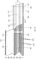
- the first and second waistbands 114a and 114b of FIG. 2 may be formed from a continuous length of layered elastic substrate 220. As discussed in more detail below and as shown in FIGS. 3A-3F , the layered elastic substrate 220 may be cut along cut line 215 to form the first waistband 114a and the second waistband 114b shown in FIG. 2 . With reference to FIG. 3A , the layered elastic substrate 220 may include a first substrate layer 238 and a second substrate layer 240 separated by an elastic material 206 to form a layered elastic substrate 220. In some exemplary configurations, the first substrate layer 238 may be formed from a first continuous substrate 202 and the second substrate layer 240 may be formed from a second continuous substrate 204 such as shown in FIG.
- the elastic material 206 may be in the form of elastic strands 208.
- the first substrate 202 may be defined by a first surface 222 and an opposing second surface 224.
- the second substrate 204 may be defined by a first surface 226 and an opposing second surface 228.
- the elastic material 206 may be located between the first surface 222 of the first substrate 202 and the first surface 226 of the second substrate 204.
- the first substrate layer 238 and/or the second substrate layer 240 of the layered elastic substrate 220 may be formed by folding a single continuous substrate 200 such as shown in FIGS. 3B-3E .
- the single continuous substrate 200 may be defined by a first edge region 230 and a second edge region 232 separated by a inner region 234, as well a first surface 216 and an opposing second surface 218.
- the first edge region 230 of the single continuous substrate 200 may be folded onto the second edge region 232 of the single continuous substrate 200 to form the first substrate layer 238 and the second substrate layer 240 as shown in FIG. 3C .
- the single continuous substrate 200 may be folded such that the first edge region 230 is proximate to the second edge region 232 so as to define a gap 236 between the first edge region 230 and the second edge region 232 such as shown in FIG. 3D .
- the first edge region 230 may abut the second edge region 232.
- the single continuous substrate 200 may be folded such that the first edge region 230 and the second edge region 232 overlap as shown in FIG. 3E .
- the single continuous substrate 200 may be folded in various ways.
- the layered elastic substrate 220 may include a first substrate layer 238 formed from a single continuous substrate 200. It is to be appreciated that the first and/or second continuous substrates 202 and 204 shown in FIG. 3A may also be folded into various configurations.
- the elastic material 206 may be in the form of elastic strands 208, ribbons 210, films 212, or combinations thereof such as shown in FIGS. 3A-3Q . While it is shown in FIGS. 3A-3F that the layered elastic substrate 220 may include eight elastic strands 208, it is to be appreciated that the layered elastic substrate 220 may include various numbers of elastic strands 208. In some exemplary configurations, the layered elastic substrate 220 may include one or more elastic films 212 such as shown in FIGS. 3G-3M . In some exemplary configurations, the layered elastic substrate 220 may include one or more elastic ribbons 210 such as shown in FIGS. 3N-3Q .
- the elastic strands 208 and/or ribbons 210 may be longitudinally spaced at constant intervals. Or, in some exemplary configurations, the elastic strands 208 and/or ribbons 210 may be longitudinally spaced at different intervals.
- the elastic material 206 may have a decitex in the range of about 480 to about 1520.
- a layered elastic substrate 220 may comprise elastic materials 206 of various decitex values. It is to be appreciated that the elastic strands 208 may have various diameters and cross-sectional geometries.
- the first waistband 114a may have a different configuration than the second waistband 114b.
- the first waistband 114a may include a different number of elastic strands or ribbons than the second waistband 114b.
- the first waistband 114a may include elastic material of a different decitex than the elastic material of the second waistband 114b.
- the first and second waistbands 114a and 114b may include various elastic materials configured in various ways.
- the first waistband 114a may include elastic strands of a different diameter and/or cross-sectional geometry than the elastic strands of the second waistband 114b.
- the layered elastic substrate may include various materials.
- the first and/or second substrate layer 238 and 240 may include woven or nonwoven webs of natural materials (e.g., wood or cotton fibers), synthetic fibers (e.g., polyolefins, polyamides, polyester, polyethylene, or polypropylene fibers) or a combination of natural and/or synthetic fibers; or coated woven or nonwoven webs.
- the first and/or the second substrate layer 238 and 240 may include a polymeric film (e.g., polyethylene or polypropylene).
- the first and/or second substrate layers 238 and 240 may include a stretchable material.
- FIGS. 4A and 4B show a process for forming discrete lengths of layered elastic substrate to be joined with absorbent articles.
- FIGS. 4A and 4B show a process for forming discrete lengths of layered elastic substrate to be joined with absorbent articles.
- various absorbent articles can be manufactured according the methods disclosed herein, such as for example, the absorbent articles disclosed in U.S. Patent Nos. 7,569,039 and 5,745,922 ; U.S. Patent Publication Nos. 2005/0107764A1 , 2012/0061016A1 , 2012/0061015A1 , and US2012/0330263 .
- FIGS. 4A and 4B show an apparatus for forming and subsequently bonding discrete waistbands 114 to a continuous length of absorbent articles 201.
- a continuous length of elastic material 206 may be joined with continuous lengths of a first and second substrate 202 and 204 to form a layered elastic substrate 220.
- the layered elastic substrate 220 may advance onto a drum 272 to be cut into discrete lengths of layered elastic substrate 194, shown in the form of discrete waistbands 114.
- FIG. 4B is a view taken along line 4B-4B of FIG. 4A .
- the elastic waistbands 114 may be intermittently bonded to the continuous length of absorbent articles 201 such that the elastic waistbands 114 are spaced apart on the continuous length of absorbent articles 201 in the second machine direction MD2.
- the continuous length of absorbent articles 201 may be combined with other components upstream or downstream of combining the discrete waistbands 114 with the absorbent articles 201.
- the continuous length of absorbent articles 201 may include various materials.
- the continuous length of absorbent articles 201 may include topsheet material, backsheet material, or combinations thereof.
- the continuous length of absorbent articles 201 may be subjected to a final cut to create discrete absorbent articles 150 having first and second waistbands.
- An exemplary process for attaching elastic components to absorbent articles is described in U.S. Provisional Patent Application No. 61/665,930 .
- the continuous length of elastic material 206 is advanced in a machine direction MD in a stretched state and the continuous lengths of first and second substrates 202 and 204 are advanced in the machine direction MD to a first metering device 250.
- the elastic material 206 is joined with the first and second substrates 202 and 204 at the first metering device 250 to form a continuous layered elastic substrate 220.
- adhesive 297 may be applied to the first substrate 202, the second substrate 204, and the elastic material 206 using an adhesive applicator 287 before advancing through the first metering device 250.
- the layered elastic substrate 220 may advance in the machine direction MD to a second metering device 252.
- the layered elastic substrate 220 may be consolidated between the first and second metering devices 250 and 252.
- the metering devices may be configured in various ways.
- the first metering device 250 shown in FIG. 4A includes a first roller 256 having an outer circumferential surface 260 and rotates about a first axis of rotation 276 and a second roller 258 having an outer circumferential surface 262 and rotates about a second axis of rotation 278.
- the first roller 256 and the second roller 258 rotate in opposite directions, and the second roller 258 is adjacent the first roller 256 to define a first nip 286 between the first roller 256 and the second roller 258.
- the first and second rollers 256 and 258 rotate such that the outer circumferential surfaces 260 and 262 have a surface speed V1.
- the 4A includes a drum 272 having an outer circumferential surface 274 and rotates about an axis of rotation 284.
- the drum 272 rotates such that the outer circumferential surface 274 has a surface speed V2.
- the layered elastic substrate 220 may advance at a surface speed V1 or less.
- the layered elastic substrate 220 consolidates in the machine direction MD from the first elongation to a second elongation that is less than the first elongation because the layered elastic substrate 220 advances at surface speed V1 at the first nip 286 of the first metering device 250 and advances at surface speed V2 at the drum 272 of the second metering device 252, wherein V2 is less than V1.
- the elastic material 206 consolidates from a first elongation to a second elongation that is less than the first elongation.
- the elastic material 206 consolidates from a first elongation to a second elongation that is less than the first elongation.
- the metering devices may include rollers, drums, conveyors, and combinations thereof.
- the metering devices may include one roller, drum, or conveyor.
- the first and second metering devices may include more than one roller, drum, conveyor, or combinations thereof.
- the metering devices may be used to consolidate the layered elastic substrate from a first elongation to a second elongation.
- the first elongation may be 150% and the second elongation may be 80%. It is to be appreciated that the methods and apparatuses disclosed herein may be used to consolidate a layered elastic substrate from a first elongation of various percentages to a second elongation of various percentages.
- the first elongation may be 110%, 120%, 130%, 140%, 150%, 160%, 170%, 180%, 190%, or 200% and the second elongation may be 10%, 20%, 30%, 40%, 50%, 60%, 70%, 80%, 90%, 100%, 110%, 120%, 130%, 140%, or 150%.
- the layered elastic substrate 220 may be cut into discrete waistbands 114 and joined with an advancing continuous length of absorbent articles 201 advancing in the second machine direction MD2.
- the continuous length of layered elastic substrate 220 may advance onto and partially wrap around the outer circumferential surface 274 of the drum 272.
- a cutter 298, shown in FIGS. 4A and 4B as a knife roll 295 for the purpose of illustration, may be positioned adjacent to the outer circumferential surface 274 of the drum 272 to cut the layered elastic substrate 220 into discrete waistbands 114.
- the drum 272 is configured with a vacuum system to hold the discrete waistbands 114 in a stretched state on the outer circumferential surface 274 of the drum 272 after being cut from the continuous layered elastic substrate 220.
- the elastic strands may retract after the layered elastic substrate is cut into discrete lengths of layered elastic substrate.
- the elastic strands 208 may be intermittently bonded to the first and second substrates layers, forming bonded regions 293 and nonbonded regions 299 in the layered elastic substrate 220.
- the cutter 298 may be configured to cut the layered elastic substrate 220 at the nonbonded regions 299 shown in FIG. 5 . Consequently, as shown in FIG. 6A , the severed ends of the elastic strands 208 retract back to the bonded regions of the waistband 114.
- the waistband 114 may have a first end portion 242 and a second end portion 244 separated by an inner portion 246 as shown in FIGS. 6A and 6B .
- the elastic material 206 may be intermittently bonded to the first and second substrate layers such that the elastic material 206 retracts back to the bonded regions located in the inner portion 246. As a result, there is no elastic material 206 located in the first and second end portions as shown in FIG. 6B .
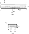
- the elastic strands 208 may be continuously bonded to the first and second substrate 202 and 204 as shown in FIG. 7 . In such an example, once the layered elastic substrate 220 is cut by the cutter 298 shown in FIGS. 4A and 4B , the elastic material 206 will extend the entire length of the waistband 114 as shown in FIG. 8 .
- a tamper apparatus 296 is used to bond the waistbands 114 to the continuous length of absorbent articles 201.
- Adhesive 297 may be applied to the discrete waistbands 114 using an adhesive applicator 287 before or while the waistbands 114 advance on the outer circumferential surface 274 of the drum 272.
- the tamper apparatus 296 may direct a portion of the continuous length of absorbent articles 201 into contact with the discrete waistband 114 advancing on the drum 272. Vacuum may be intermittently interrupted from the drum 272 to allow the discrete waistband 114 to release from the outer circumferential surface 274 of the drum 272.
- the discrete waistband 114 may bond to the continuous length of absorbent articles 201 in a stretched state.
- the tamper apparatus 296 may shift away from the drum 272 to allow the discrete waistband 114 to be removed from the drum 272.
- the continuous length of absorbent articles 201 then advances in the second machine direction MD2 and subsequent discrete waistbands 114 are bonded to the continuous length of absorbent articles 201 such that discrete waistbands 114 are spaced apart from each other discrete waistband 114 in the second machine direction MD2 as shown in FIG. 4C .
- the absorbent articles 201 having waistbands 114 may advance in the second machine direction MD2 through a nip 289 and be cut by a rotating knife roll 295 in the second cross direction CD2 into discrete absorbent articles 150.
- the waistbands 114 may be defined by a first edge region 340 and a second edge region 342 separated along the cross direction CD by an inner region 344 as shown in FIG. 4C .
- the continuous length of absorbent articles 201 may be cut along the inner region 344 of the discrete waistbands 114, thereby forming a first waistband 114a on an absorbent article 150 and a second waistband 114b on a subsequently advancing absorbent article 150.
- FIG. 4C is a view of taken along line 4C-4C of FIG. 4B and FIG. 4D is a view taken alone line 4D-4D of FIG. 4B .
- the continuous length of absorbent articles 201 may be cut adjacent to the waistband 114, either before or after the waistband 114, thereby creating an absorbent article 150 having only one waistband 114. It is to be appreciated that the absorbent articles may have waistbands arranged in various configurations.
- FIG. 9A shows a waistband 114 having gathers 115 when the absorbent article 150 is relaxed
- FIG. 9B shows a waistband 114 having gathers 115 when the absorbent article is fully stretched.
- the waistband 114 has gathers 115 when the absorbent article 150 is fully stretched.
- FIGS. 1A, 1B , 9A, and 9B it is to be appreciated that a waistband 114 with gathers 115 may have an increased basis weight compared with a waistband without gathers.
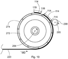
- the discrete waistbands 114 may be further consolidated while advancing on the outer circumferential surface 274 of the drum 272 as shown in FIG. 10 .
- the waistbands 114 may have a first end portion 242 and a second end portion 244 separated along the ma by an inner portion 246.
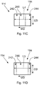
- the drum 272 may be configured to increase the vacuum pressure, and thus decrease the vacuum force, applied to the first and second end portions 242 and 244 of the waistband 114 such that the waistband 114 consolidates from a second length L2 to a third length L3 as shown in FIG. 11B . As shown in FIG.
- FIG. 11A is a view taken along line 11A-11A of FIG. 10
- FIG. 11B is a view taken along line 11B-11B of FIG. 10
- vacuum pressure applied to the first end portion 242, second end portion 244, and the inner portion 246 of the discrete waistband 114 may be increased so that the first end portion 242, second end portion 244, and the inner portion 246 consolidate, and the waistband consolidates from a second length L2 to a fourth length L4 shown in FIG. 11C .
- vacuum pressure applied to the first and second end portions 242 and 244 may be increased such that the first and second end portions 242 and 244 relax and the waistband consolidates from a second length L2 to a fifth length L5 as shown in FIG. 11D .
- Methods and apparatuses for consolidating elastic substrates are described in U.S. Provisional Patent Application No. 61/665,933 .
- FIG. 12 shows another exemplary apparatus for assembling discrete lengths of layered elastic substrate 194.
- a continuous length of elastic material 306 may advance in a machine direction MD to a first metering device 350.
- the continuous length of elastic material 306 may then advance in the machine direction MD to a second metering device 352.
- the first and second metering devices 350 and 352 act to stretch the elastic material 306 along the machine direction MD between the first and second metering devices 350 and 352.
- a continuous length of first substrate 302 and a continuous length of second substrate material 304 are advanced in the machine direction MD.
- the elastic material 306 is combined with the first and second substrate 302 and 304 at the second metering device 352 to form a layered elastic substrate 320.
- adhesive 397 may be applied to the first substrate 302, the second substrate 304, and the elastic material 306 using an adhesive applicator 387 before advancing through the second metering device 352.
- the layered elastic substrate 320 may advance in the machine direction MD to a third metering device 354.
- the layered elastic substrate 320 consolidates between the second and third metering devices 352 and 354.
- the first metering device 350 may include a first roller 356 having an outer circumferential surface 360 and rotates about a first axis of rotation 376 and a second roller 358 having an outer circumferential surface 362 and rotates about a second axis of rotation 378.
- the first roller 356 and the second roller 358 rotate in opposite directions, and the second roller 358 is adjacent the first roller 356 to define a first nip 386 between the first roller 356 and the second roller 358.
- the first and second rollers 356 and 358 rotate such that the outer circumferential surfaces 360 and 362 each have a surface speed V1.
- the second metering device 352 includes a first roller 364 having an outer circumferential surface 368 and rotates about a first axis of rotation 380 and a second roller 366 having an outer circumferential surface 370 and rotates about a second axis of rotation 382.
- the first roller 364 and the second roller 366 rotate in opposite directions, and the second roller 366 is adjacent the first roller 364 to define a second nip 388 between the first roller 364 and the second roller 366.
- the first and second rollers 364 and 366 rotate such that the outer circumferential surfaces 368 and 370 each have a surface speed V2.
- the surface speed V2 may be greater than the surface speed V1 such that the elastic material 306 stretches from a first elongation to a second elongation that is greater than the first elongation between the first metering device 350 and the second metering device 352.
- the third metering device 354 may include a drum 372 having an outer circumferential surface 374 and rotates about an axis of rotation 384. The drum 372 rotates such that the outer circumferential surface 374 has a surface speed V3.
- the surface speed V3 may be less than the surface speed V2, but greater than the surface speed V1, such that the layered elastic substrate 320 consolidates from a second elongation to a third elongation that is less than the second elongation and greater than the first elongation.
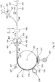
- FIG. 13 shows another exemplary apparatus for assembling discrete lengths of layered elastic substrate.
- a continuous length of elastic material 406, shown in the form of elastic strands 408 for exemplary purpose only, may advance in a stretched state in a machine direction MD and a single continuous substrate 400 may advance in a machine direction MD.
- the single continuous substrate 400 may be folded over the elastic strands 408 at a folding apparatus 494.
- adhesive 497 may be applied to the single continuous substrate 400 and the continuous elastic strands 408 using an adhesive applicator 487 before advancing through the folding apparatus 494. From the folding apparatus 494, the single continuous substrate 400 and the continuous elastic strands 408 advances through a first metering device 450.
- the elastic material 406 is bonded to the single continuous substrate 400 to form the layered elastic substrate 420 at the first metering device 450. From the first metering device 450, the layered elastic substrate 420 advances in the machine direction MD to a second metering device 452. The layered elastic substrate 420 is consolidated between the first and second metering 450 and 452.
- FIGS. 14 and 15 show two exemplary folding configurations for the single continuous substrate 400. It is to be appreciated that FIGS. 14 and 15 are alternative views taken along line A-A of FIG. 13 .
- the single continuous substrate 400 of FIG. 13 may include a first surface 416 and an opposing second surface 418.
- the single continuous substrate 400 may be defined by a first edge region 430 and second edge region 432 separated along the cross direction CD by an inner region 434.
- the single continuous substrate 400 may be folded at a fold line 411 in the inner region 434 along the machine direction MD such that the first edge region 430 and the second edge region 432 of the first surface 416 are in a facing relationship such as shown in FIG. 14 .
- the single continuous substrate 400 may be folded at two fold lines 411 in each of the first and second edge regions 430 and 432 in the machine direction MD such that the first surface 416 of each of the first edge region 430 and the second edge region 432 are in a facing relationship with the first surface 416 of the inner region 434.
- first and second lateral edges 433 and 435 are overlapping such that a portion of the first surface 416 of the second edge region 432 is in a facing relationship with a portion of the second surface 418 of the first edge region 430 and portions of the first surface 416 of the first and second edge regions 430 and 432 are in a facing relationship with the first surface 416 of the inner region 434.
- the first and second lateral edges 433 and 435 may be arranged in various configurations. For example, as shown in FIG. 3D , the single continuous substrate 400 may be folded such that the first lateral edge 433 is adjacent to the second lateral edge 435, and in some embodiments, the first lateral edge 433 may abut the second lateral edge 435.
- the elastic strands 408 may be intermittently bonded to the single continuous substrate 400 to form the layered elastic substrate 420.
- adhesive 497 (represented by cross-hatched areas) may be applied to the elastic strands 408 intermittently in the machine direction MD.
- the layered elastic substrate 420 has bonded regions 493 where the elastic strands 408 is bonded to the single continuous substrate 400, the nonbonded regions 499 where the elastic strands 408 are not bonded to the single continuous substrate 400.
- dashed lines 491 are shown in FIG. 14 to represent example boundaries between the nonbonded regions 499 and the bonded regions 493 of the layered elastic substrate 420. As shown in FIG.
- the continuous elastic strands 408 may be continuously bonded to the single continuous substrate 400 to form the layered elastic substrate 420.
- adhesive 497 (represented by cross-hatched areas) may be applied continuously to the elastic strands 408 such that when it is joined with the single continuous substrate 400, it bonds to the single continuous substrate 400 continuously along the entire length of the single continuous substrate 400.
- the elastic material may also be intermittently or continuously bonded to the first and second continuous substrates.
- the first metering device 450 includes a first roller 456 having an outer circumferential surface 460 and rotates about a first axis of rotation 476 and a second roller 458 having an outer circumferential surface 462 and rotates about a second axis of rotation 478.
- the first roller 456 and the second roller 458 rotate in opposite directions, and the second roller 458 is adjacent the first roller 456 to define a first nip 486 between the first roller 456 and the second roller 458.
- the first and second rollers 456 and 458 rotate such that the outer circumferential surfaces 460 and 462 have a surface speed V1.
- the 13 includes a drum 472 having an outer circumferential surface 474 and rotates about an axis of rotation 484.
- the drum 472 rotates such that the outer circumferential surface 474 has a surface speed V2.
- the surface speed V1 may be greater than the surface speed V2 such that the layered elastic substrate 420 consolidates in the machine direction MD between the first metering device 450 and the second metering device 452 from a first elongation to a second elongation that is less than the first elongation.
- FIG. 16 shows another exemplary process assembling discrete lengths of layered elastic substrate.
- a continuous length of elastic material 506 may be advanced in a machine direction MD to a first metering device 550.
- a single continuous substrate 500 is advanced in the machine direction MD.
- the single continuous substrate 500 is folded over the elastic material 506 at a folding apparatus 594.
- Adhesive 597 may be applied to the single continuous substrate 500 and the elastic material 506 by an adhesive applicator 587 before advancing through the folding apparatus 594.
- the continuous lengths of elastic material 506 and single continuous substrate 500 are advanced through a second metering device 552 that acts to bond the elastic material 506 to the single continuous substrate 500 to form a layered elastic substrate 520.
- the first and second metering devices 550 and 552 also act to stretch the advancing continuous length of elastic material 506 between the first and second metering devices 550 and 552 from a first elongation to a second elongation that is greater than the first elongation.
- the layered elastic substrate 520 then advances in the machine direction MD to a third metering device 554.
- the layered elastic substrate 520 is consolidated in the machine direction MD between the second and third metering devices 552 and 554 from a second elongation to a third elongation that is less than the second elongation and greater than the first elongation. It is to be appreciated that the folding apparatus of FIG. 16 may be configured to fold the single continuous substrate 500 in various ways, such as those described above with regard to FIGS. 13-15 .
- the first metering device 550 may include a first roller 556 having an outer circumferential surface 560 and rotates about a first axis of rotation 576.
- the first roller 556 rotates such that the outer circumferential surface 560 have a surface speed V1.
- the second metering device 552 may include a first roller 558 having an outer circumferential surface 562 and rotates about a first axis of rotation 578 and a second roller 564 having an outer circumferential surface 568 and rotates about a second axis of rotation 580.
- the first roller 558 and the second roller 564 rotate in opposite directions, and the second roller 564 is adjacent the first roller 558 to define a first nip 586 between the first roller 564 and the second roller 566.
- the first and second rollers 558 and 564 rotate such that the outer circumferential surfaces 562 and 568 have a surface speed V2.
- the surface speed V2 may be greater than the surface speed V1 such that the elastic material 506 stretches in the machine direction MD from a first elongation to a second elongation that is greater than the first elongation between the first metering device 550 and the second metering device 552.
- the third metering device 554 may include a drum 572 having an outer circumferential surface 574 and rotates about an axis of rotation 584.
- the drum 572 rotates such that the outer circumferential surface 574 has a surface speed V3.
- the surface speed V3 may be less than the surface speed V2, but greater than the surface speed V1, such that the layered elastic substrate 520 consolidates in the machine direction MD between the second and third metering devices 552 and 554, from a second elongation to a third elongation that is less than the second elongation and greater than the first elongation.
Claims (12)
- Procédé pour fabriquer un substrat élastique en couches (220), le couper en bandes de ceinture distinctes et joindre celles-ci à des articles absorbants, le procédé comprenant les étapes consistant à :faire avancer une première couche de substrat (238, 202) dans une direction machine (MD), ayant une première surface (226, 216) et une deuxième surface opposée (224, 218) ;faire avancer une deuxième couche de substrat (240, 204) dans la direction machine, ayant une première surface (226, 216) et une deuxième surface opposée (228, 218) ;faire avancer un matériau élastique (206) dans un état étiré dans la direction machine (MD) ;lier le matériau élastique (206) dans l'état étiré à la première surface (222, 216) de la première couche de substrat (238) et à la première surface (226, 216) de la deuxième couche de substrat (240) pour former un substrat élastique en couches (220) ;faire avancer le substrat élastique en couches (220) à travers un premier dispositif de mesure (250) à une première vitesse (V1) ;faire avancer le substrat élastique en couches à travers un deuxième dispositif de mesure (252) à une deuxième vitesse (V2) à la suite de l'avancement du substrat élastique en couches (220) à travers le premier dispositif de mesure (250), dans lequel la première vitesse (V1) est supérieure à la deuxième vitesse (V2) ;caractérisé en ce que le procédé comprend en outre les étapes consistant à :couper le substrat élastique en couches en bandes de ceinture distinctes (114) alors qu'une longueur continue de substrat élastique en couches (220) a avancé sur, et s'est partiellement enveloppée autour de, la surface circonférentielle externe (274) d'un tambour (272), le tambour étant configuré avec un système de vide pour maintenir les bandes de ceinture distinctes dans un état étiré sur la surface circonférentielle externe du tambour après être coupées du substrat élastique en couches continu (220) ;utiliser un appareil de compactage (296) pour joindre les bandes de ceinture distinctes vers une longueur continue avançante d'articles absorbants (201) avançant dans une deuxième direction machine (MD), dans lequel les bandes de ceinture distinctes sont liées à la longueur continue d'articles absorbants dans un état étiré.
- Procédé selon la revendication 1, dans lequel le matériau élastique comprend un fil élastique (208).
- Procédé selon la revendication 1, dans lequel le matériau élastique (206) comprend un film élastique (212).
- Procédé selon l'une quelconque des revendications précédentes, comprenant en outre les étapes consistant à étirer le matériau élastique (206) à un premier allongement au niveau du premier dispositif de mesure (250) ; et relâcher le matériau élastique (206) à un deuxième allongement entre les premier et deuxième dispositifs de mesure (250, 252).
- Procédé selon la revendication 4, dans lequel le premier allongement est d'environ 150 % et le deuxième allongement est d'environ 80 %.
- Procédé selon l'une quelconque des revendications précédentes, dans lequel le premier dispositif de mesure (250) comprend un premier rouleau (256) tournant autour d'un premier axe de rotation (276), le premier rouleau (256) ayant une surface circonférentielle externe (260) se déplaçant à la première vitesse (V1).
- Procédé selon la revendication 6, dans lequel le premier dispositif de mesure (250) comprend en outre un deuxième rouleau (258) tournant autour d'un deuxième axe de rotation (278), le deuxième rouleau (258) ayant une surface circonférentielle externe (262) se déplaçant à la première vitesse (V1), dans lequel le premier rouleau (256) et le deuxième rouleau (258) tournent dans des directions opposées, dans lequel le deuxième rouleau (258) se situe adjacent au premier rouleau (256) pour définir une première ligne de contact (286) entre le premier rouleau (256) et le deuxième rouleau (258).
- Procédé selon l'une quelconque des revendications précédentes, dans lequel le deuxième dispositif de mesure (252) comprend un premier rouleau (272, 364) tournant autour d'un premier axe de rotation (284, 380), le premier rouleau (272, 364) ayant une surface circonférentielle externe (274, 368) se déplaçant à la deuxième vitesse (V2).
- Procédé selon la revendication 8, dans lequel le deuxième dispositif de mesure (252) comprend en outre un deuxième rouleau (366) tournant autour d'un deuxième axe de rotation (382), le deuxième rouleau (366) ayant une surface circonférentielle externe (370) se déplaçant à la deuxième vitesse (V2), dans lequel le premier rouleau (364) et le deuxième rouleau (366) tournent dans des directions opposées, dans lequel le deuxième rouleau (366) se situe adjacent au premier rouleau (364) pour définir une deuxième ligne de contact (388) entre le premier rouleau (364) et le deuxième rouleau (366).
- Procédé selon l'une quelconque des revendications précédentes, comprenant en outre les étapes consistant à :couper le substrat élastique en couches (220) en longueurs distinctes de substrat élastique en couches (194) à la suite de l'avancement du substrat élastique en couches (220) à travers le deuxième dispositif de mesure (252), dans lequel les longueurs distinctes de substrat élastique en couches (194) définissent chacune une première région de bord (340) et une deuxième région de bord (342) séparées le long d'une direction croisée (CD) par une région interne (344) ;faire avancer une longueur continue de matériau en bande (245) dans une deuxième direction machine (MD2) ;lier chaque longueur distincte de substrat élastique en couches (194) à la longueur continue de matériau de nappe (245) dans lequel les longueurs distinctes de substrat élastique en couches (194) sont espacées les unes des autres le long de la deuxième direction machine (MD2) ; et couper la longueur continue de matériau de nappe (245) le long des régions internes (344) de chaque longueur distincte de substrat élastique en couches (194) pour séparer la longueur continue de matériau de nappe (245) en couches distinctes (152).
- Procédé selon l'une quelconque des revendications précédentes, comprenant en outre les étapes consistant à :faire avancer un substrat continu unique (200) ayant une première surface (216) et une deuxième surface opposée (218) dans la direction machine (MD), dans lequel le substrat continu unique (200) inclut des premier et deuxième bords latéraux opposés (433, 435) et des première et deuxième régions de bord longitudinalement opposées (430, 432) séparées le long de la direction croisée (CD) par une région interne (434) ; etformer les première et deuxième couches de substrat (238, 240) en repliant la première surface (216) de la première région de bord (430) du substrat continu unique (200) sur une partie de la première surface (216) de l'une ou l'autre parmi la première région de bord (430), la région interne (434) ou la deuxième région de bord (432) du substrat continu unique (200).
- Procédé selon l'une quelconque des revendications précédentes, dans lequel l'étape de liaison du matériau élastique (206) comprend en outre une liaison intermittente du matériau élastique (206).
Applications Claiming Priority (2)
| Application Number | Priority Date | Filing Date | Title |
|---|---|---|---|
| US201261665942P | 2012-06-29 | 2012-06-29 | |
| PCT/US2013/048387 WO2014004938A1 (fr) | 2012-06-29 | 2013-06-28 | Procédé de fabrication d'un substrat élastique stratifié comprenant des fronces |
Publications (2)
| Publication Number | Publication Date |
|---|---|
| EP2867023A1 EP2867023A1 (fr) | 2015-05-06 |
| EP2867023B1 true EP2867023B1 (fr) | 2019-04-03 |
Family
ID=48793552
Family Applications (1)
| Application Number | Title | Priority Date | Filing Date |
|---|---|---|---|
| EP13737493.0A Active EP2867023B1 (fr) | 2012-06-29 | 2013-06-28 | Procédé de fabrication d'un substrat élastique stratifié comprenant des fronces |
Country Status (5)
| Country | Link |
|---|---|
| US (1) | US9289941B2 (fr) |
| EP (1) | EP2867023B1 (fr) |
| JP (1) | JP6211606B2 (fr) |
| CN (1) | CN104395082B (fr) |
| WO (1) | WO2014004938A1 (fr) |
Families Citing this family (11)
| Publication number | Priority date | Publication date | Assignee | Title |
|---|---|---|---|---|
| EP2866753A1 (fr) | 2012-06-29 | 2015-05-06 | The Procter & Gamble Company | Système et procédé pour l'application continue à grande vitesse d'un matériau de bande sur un matériau de substrat mobile du type feuille |
| JP2017516543A (ja) | 2014-05-29 | 2017-06-22 | ザ プロクター アンド ギャンブル カンパニー | 分離バリア部材を含む吸収性物品の製造方法 |
| US10390999B2 (en) | 2014-05-29 | 2019-08-27 | The Procter & Gamble Company | Method and apparatus for manufacturing an absorbent article including a discrete substrate having a rugosity |
| EP3265041A1 (fr) | 2015-03-06 | 2018-01-10 | The Procter and Gamble Company | Procédé de fabrication d'articles absorbants comprenant un élément barrière discret |
| WO2016144617A1 (fr) | 2015-03-06 | 2016-09-15 | The Procter & Gamble Company | Procédé de fabrication d'articles absorbants comprenant un élément barrière discret |
| ITUB20153482A1 (it) * | 2015-09-08 | 2015-12-08 | Fameccanica Data Spa | Nastro composito tridimensionale, procedimento ed apparecchio per la sua produzione |
| US11129757B2 (en) | 2016-05-20 | 2021-09-28 | The Procter & Gamble Company | Absorbent article having waist gasketing element |
| CN109069313B (zh) | 2016-05-20 | 2021-10-26 | 宝洁公司 | 具有腰部衬圈元件的吸收制品 |
| US11096835B2 (en) * | 2016-12-19 | 2021-08-24 | The Procter & Gamble Company | Methods for sealing absorbent cores on absorbent articles |
| IT201700065365A1 (it) * | 2017-06-13 | 2017-09-13 | Fameccanica Data Spa | Apparecchiatura e procedimento per produrre un nastro composito elasticizzato con tratti elastici intermittenti |
| JP7262958B2 (ja) * | 2018-10-04 | 2023-04-24 | ユニ・チャーム株式会社 | 伸縮性シートの製造方法、及び、伸縮性シートの製造装置 |
Family Cites Families (100)
| Publication number | Priority date | Publication date | Assignee | Title |
|---|---|---|---|---|
| US3911173A (en) | 1973-02-05 | 1975-10-07 | Usm Corp | Adhesive process |
| US3848594A (en) | 1973-06-27 | 1974-11-19 | Procter & Gamble | Tape fastening system for disposable diaper |
| US3860003B2 (en) | 1973-11-21 | 1990-06-19 | Contractable side portions for disposable diaper | |
| US3929135A (en) | 1974-12-20 | 1975-12-30 | Procter & Gamble | Absorptive structure having tapered capillaries |
| US4342314A (en) | 1979-03-05 | 1982-08-03 | The Procter & Gamble Company | Resilient plastic web exhibiting fiber-like properties |
| US4324246A (en) | 1980-05-12 | 1982-04-13 | The Procter & Gamble Company | Disposable absorbent article having a stain resistant topsheet |
| US4381781A (en) | 1981-01-05 | 1983-05-03 | Kimberly-Clark Corporation | Flexible waist diaper |
| US4463045A (en) | 1981-03-02 | 1984-07-31 | The Procter & Gamble Company | Macroscopically expanded three-dimensional plastic web exhibiting non-glossy visible surface and cloth-like tactile impression |
| US4808178A (en) | 1981-07-17 | 1989-02-28 | The Proctor & Gamble Company | Disposable absorbent article having elasticized flaps provided with leakage resistant portions |
| US4909803A (en) | 1983-06-30 | 1990-03-20 | The Procter And Gamble Company | Disposable absorbent article having elasticized flaps provided with leakage resistant portions |
| US4610678A (en) | 1983-06-24 | 1986-09-09 | Weisman Paul T | High-density absorbent structures |
| US4573986A (en) | 1984-09-17 | 1986-03-04 | The Procter & Gamble Company | Disposable waste-containment garment |
| PH23956A (en) | 1985-05-15 | 1990-01-23 | Procter & Gamble | Absorbent articles with dual layered cores |
| US4609518A (en) | 1985-05-31 | 1986-09-02 | The Procter & Gamble Company | Multi-phase process for debossing and perforating a polymeric web to coincide with the image of one or more three-dimensional forming structures |
| US4629643A (en) | 1985-05-31 | 1986-12-16 | The Procter & Gamble Company | Microapertured polymeric web exhibiting soft and silky tactile impression |
| US4695278A (en) | 1985-10-11 | 1987-09-22 | The Procter & Gamble Company | Absorbent article having dual cuffs |
| US4662875A (en) | 1985-11-27 | 1987-05-05 | The Procter & Gamble Company | Absorbent article |
| IL82511A (en) | 1986-05-28 | 1992-09-06 | Procter & Gamble | Apparatus for and methods of airlaying fibrous webs having discrete particles therein |
| US4834735A (en) | 1986-07-18 | 1989-05-30 | The Proctor & Gamble Company | High density absorbent members having lower density and lower basis weight acquisition zones |
| CA1290501C (fr) | 1986-10-10 | 1991-10-15 | Jerry Layne Dragoo | Article absorbant ayant deux revers pare-fuite |
| US4846815A (en) | 1987-01-26 | 1989-07-11 | The Procter & Gamble Company | Disposable diaper having an improved fastening device |
| ES2042612T3 (es) | 1987-03-07 | 1993-12-16 | Fuller H B Licensing Financ | Procedimiento para la union permanente de elementos dilatables en forma de hilos o de cintas sobre un substrato superficial asi como utilizacion del mismo para la fabricacion de sectores de banda de hojas rizadas. |
| US4785996A (en) | 1987-04-23 | 1988-11-22 | Nordson Corporation | Adhesive spray gun and nozzle attachment |
| US4857067A (en) | 1987-12-04 | 1989-08-15 | Minnesota Mining And Manufacturing Company | Disposable diaper having shirred ears |
| US4963140A (en) | 1987-12-17 | 1990-10-16 | The Procter & Gamble Company | Mechanical fastening systems with disposal means for disposable absorbent articles |
| JPH0759242B2 (ja) * | 1987-12-31 | 1995-06-28 | 株式会社瑞光 | 使い捨ておむつの製造方法 |
| US4894060A (en) | 1988-01-11 | 1990-01-16 | Minnesota Mining And Manufacturing Company | Disposable diaper with improved hook fastener portion |
| US4988344A (en) | 1988-05-24 | 1991-01-29 | The Procter & Gamble Company | Absorbent articles with multiple layer absorbent layers |
| US4988345A (en) | 1988-05-24 | 1991-01-29 | The Procter & Gamble Company | Absorbent articles with rapid acquiring absorbent cores |
| US5006394A (en) | 1988-06-23 | 1991-04-09 | The Procter & Gamble Company | Multilayer polymeric film |
| US4925520A (en) * | 1988-08-11 | 1990-05-15 | Curt G. Joa, Inc. | Apparatus for applying an elastic waistband transversely of a longitudinally moving web |
| US4946527A (en) | 1989-09-19 | 1990-08-07 | The Procter & Gamble Company | Pressure-sensitive adhesive fastener and method of making same |
| US5137537A (en) | 1989-11-07 | 1992-08-11 | The Procter & Gamble Cellulose Company | Absorbent structure containing individualized, polycarboxylic acid crosslinked wood pulp cellulose fibers |
| EP0565606B1 (fr) | 1991-01-03 | 1995-03-08 | The Procter & Gamble Company | Article absorbant dote d'une ame absorbante multicouche a absorption rapide |
| US5221274A (en) | 1991-06-13 | 1993-06-22 | The Procter & Gamble Company | Absorbent article with dynamic elastic waist feature having a predisposed resilient flexural hinge |
| US5151092A (en) | 1991-06-13 | 1992-09-29 | The Procter & Gamble Company | Absorbent article with dynamic elastic waist feature having a predisposed resilient flexural hinge |
| US5147345A (en) | 1991-08-12 | 1992-09-15 | The Procter & Gamble Company | High efficiency absorbent articles for incontinence management |
| US5387207A (en) | 1991-08-12 | 1995-02-07 | The Procter & Gamble Company | Thin-unit-wet absorbent foam materials for aqueous body fluids and process for making same |
| US5260345A (en) | 1991-08-12 | 1993-11-09 | The Procter & Gamble Company | Absorbent foam materials for aqueous body fluids and absorbent articles containing such materials |
| US5342338A (en) | 1993-06-11 | 1994-08-30 | The Procter & Gamble Company | Disposable absorbent article for low-viscosity fecal material |
| US5916663A (en) | 1993-08-03 | 1999-06-29 | Chappell; Charles W. | Web materials exhibiting elastic-like behavior |
| US5518801A (en) | 1993-08-03 | 1996-05-21 | The Procter & Gamble Company | Web materials exhibiting elastic-like behavior |
| EP0714272B1 (fr) | 1993-08-17 | 1999-07-21 | The Procter & Gamble Company | Article absorbant jetable pouvant retenir les matieres fecales de faible viscosite |
| US5941864A (en) | 1993-08-17 | 1999-08-24 | The Procter & Gamble Company | Disposable absorbent article having improved fecal storage |
| US5693165A (en) | 1993-11-04 | 1997-12-02 | The Procter & Gamble Company | Method and apparatus for manufacturing an absorbent article |
| SG72621A1 (en) | 1993-11-19 | 2000-05-23 | Procter & Gamble | Absorbent article with multi-directional extensible side panels |
| EP0657502A1 (fr) | 1993-12-13 | 1995-06-14 | Du Pont De Nemours International S.A. | Composition thermoplastique contenant un agent compatibilisant |
| US5599335A (en) | 1994-03-29 | 1997-02-04 | The Procter & Gamble Company | Absorbent members for body fluids having good wet integrity and relatively high concentrations of hydrogel-forming absorbent polymer |
| US5500063A (en) * | 1994-06-28 | 1996-03-19 | Kimberly-Clark Corporation | Method of joining an elastic band to a continuously moving partially elastic substrate |
| US5595567A (en) | 1994-08-09 | 1997-01-21 | The Procter & Gamble Company | Nonwoven female component for refastenable fastening device |
| US5650222A (en) | 1995-01-10 | 1997-07-22 | The Procter & Gamble Company | Absorbent foam materials for aqueous fluids made from high internal phase emulsions having very high water-to-oil ratios |
| US5624427A (en) | 1995-01-18 | 1997-04-29 | The Procter & Gamble Company | Female component for refastenable fastening device |
| US5745922A (en) | 1995-01-31 | 1998-05-05 | Kimberly Clark Corporation | Disposable garment and related manufacturing equipment and methods |
| US5580411A (en) | 1995-02-10 | 1996-12-03 | The Procter & Gamble Company | Zero scrap method for manufacturing side panels for absorbent articles |
| US5571096A (en) | 1995-09-19 | 1996-11-05 | The Procter & Gamble Company | Absorbent article having breathable side panels |
| US5865823A (en) | 1996-11-06 | 1999-02-02 | The Procter & Gamble Company | Absorbent article having a breathable, fluid impervious backsheet |
| US6677258B2 (en) | 1996-05-29 | 2004-01-13 | E. I. Du Pont De Nemours And Company | Breathable composite sheet structure and absorbent articles utilizing same |
| US5735840A (en) | 1996-09-20 | 1998-04-07 | The Procter & Gamble Company | Disposable diaper with integral backsheet landing zone |
| JP3606297B2 (ja) * | 1996-10-21 | 2005-01-05 | 株式会社リブドゥコーポレーション | 使い捨ておむつの製造方法および該方法で得られた使い捨ておむつ |
| ATE243012T1 (de) | 1997-04-18 | 2003-07-15 | Procter & Gamble | Verwendung von hydrogelformende polymere in absorbierende materialen zur aufnahme von körperflüssigkeiten |
| DE69724110T2 (de) | 1997-06-25 | 2004-06-17 | The Procter & Gamble Company, Cincinnati | Absorbierender Wegwerfartikel mit geringem Feuchtigkeitsgehalt |
| US6432098B1 (en) | 1997-09-04 | 2002-08-13 | The Procter & Gamble Company | Absorbent article fastening device |
| US6251097B1 (en) | 1997-09-04 | 2001-06-26 | The Procter & Gamble Company | Absorbent article fastening device |
| US6013063A (en) | 1997-11-14 | 2000-01-11 | The Procter & Gamble Company | Viscous fluid bodily waste management article |
| SE512365C2 (sv) | 1998-07-08 | 2000-03-06 | Sca Hygiene Prod Ab | Förfarande och anordning för fastsättning av materialstycken på en kontinuerlig bana |
| US6652693B2 (en) * | 1998-08-06 | 2003-11-25 | Kimberly-Clark Worldwide, Inc. | Process for applying adhesive in an article having a strand material |
| JP4421012B2 (ja) * | 1999-06-16 | 2010-02-24 | 株式会社瑞光 | 使い捨てパンツ及びその製造方法 |
| US6596108B2 (en) | 2001-10-10 | 2003-07-22 | Curt G. Joa, Inc. | Web velocity modulator |
| US20050013975A1 (en) * | 2003-07-14 | 2005-01-20 | Nordson Corporation | Method of securing elastic strands to flat substrates and products produced by the method |
| ES2428693T3 (es) | 2003-02-12 | 2013-11-08 | The Procter & Gamble Company | Núcleo absorbente para un artículo absorbente |
| ATE523180T1 (de) | 2003-02-12 | 2011-09-15 | Procter & Gamble | Saugfähiger kern für einen saugfähigen artikel |
| US7569039B2 (en) | 2003-11-19 | 2009-08-04 | The Procter & Gamble Company | Disposable pull-on garment |
| US7648771B2 (en) * | 2003-12-31 | 2010-01-19 | Kimberly-Clark Worldwide, Inc. | Thermal stabilization and processing behavior of block copolymer compositions by blending, applications thereof, and methods of making same |
| US20050215972A1 (en) | 2004-03-29 | 2005-09-29 | Roe Donald C | Disposable absorbent articles with zones comprising elastomeric components |
| DE602004026566D1 (de) | 2004-07-28 | 2010-05-27 | Procter & Gamble | Indirekter Druck von AMG |
| US7513969B2 (en) * | 2004-10-15 | 2009-04-07 | The Procter & Gamble Company | Method for producing a corrugated stretch laminate with a free formed printed elastic member |
| US20060111686A1 (en) * | 2004-11-23 | 2006-05-25 | Uwe Schneider | Absorbent article with heat deactivated area |
| US7612001B2 (en) * | 2004-12-22 | 2009-11-03 | Kimberly-Clark Worldwide, Inc. | High performance elastic materials made using styrene block copolymers and mixtures |
| US20060148358A1 (en) * | 2004-12-30 | 2006-07-06 | Hall Gregory K | Elastic laminate and process therefor |
| US8328782B2 (en) | 2005-02-18 | 2012-12-11 | The Procter & Gamble Company | Hydrophobic surface coated light-weight nonwoven laminates for use in absorbent articles |
| US8211079B2 (en) | 2005-09-30 | 2012-07-03 | The Procter & Gamble Company | Anti-pop open macrofasteners |
| US7799006B2 (en) | 2005-09-30 | 2010-09-21 | The Procter & Gamble Company | Fastening system having multiple engagement orientations |
| US7432413B2 (en) | 2005-12-16 | 2008-10-07 | The Procter And Gamble Company | Disposable absorbent article having side panels with structurally, functionally and visually different regions |
| US20070142798A1 (en) | 2005-12-16 | 2007-06-21 | The Procter & Gamble Company | Disposable absorbent article having serviceable indicia indicating improper fit |
| US20070219521A1 (en) | 2006-03-17 | 2007-09-20 | The Procter & Gamble Company | Absorbent article comprising a synthetic polymer derived from a renewable resource and methods of producing said article |
| US20070287983A1 (en) | 2006-06-07 | 2007-12-13 | Richard Worthington Lodge | Absorbent article having an anchored core assembly |
| US9072633B2 (en) | 2006-06-07 | 2015-07-07 | The Procter & Gamble Company | Biaxially stretchable outer cover for an absorbent article |
| US8235963B2 (en) | 2006-06-07 | 2012-08-07 | The Procter & Gamble Company | Disposable wearable absorbent articles with anchoring systems |
| JP5015263B2 (ja) | 2006-11-29 | 2012-08-29 | ザ プロクター アンド ギャンブル カンパニー | 3次元外観を与えるパターンが印刷された基材 |
| US8399368B2 (en) * | 2007-10-16 | 2013-03-19 | Kimberly-Clark Worldwide, Inc. | Nonwoven web material containing a crosslinked elastic component formed from a linear block copolymer |
| US20090294044A1 (en) | 2008-05-27 | 2009-12-03 | Nathan Alan Gill | Methods and Apparatus for Attaching Elastic Components to Absorbent Articles |
| US8691041B2 (en) | 2008-08-08 | 2014-04-08 | The Procter And Gamble Company | Method of producing a composite multi-layered printed absorbent article |
| WO2010050867A1 (fr) * | 2008-11-03 | 2010-05-06 | Sca Hygiene Products Ab | Procédé de production d'articles de type pantalon possédant une structure de châssis, et articles de type pantalon produits selon ce procédé |
| US8377249B2 (en) | 2009-04-03 | 2013-02-19 | The Procter & Gamble Company | Appraratus and method for providing a localized speed variance of an advancing substrate |
| JP5608361B2 (ja) * | 2009-12-17 | 2014-10-15 | 花王株式会社 | シートの転写装置 |
| US9498386B2 (en) * | 2010-09-10 | 2016-11-22 | The Procter & Gamble Company | Method of making disposable absorbent diaper pants |
| US20120061015A1 (en) | 2010-09-14 | 2012-03-15 | Gary Dean Lavon | Method of Making Prefastened Refastenable Disposable Absorbent Articles |
| US8945326B2 (en) | 2010-09-14 | 2015-02-03 | The Procter & Gamble Company | Method of making prefastened refastenable disposable absorbent articles |
| US20120273129A1 (en) | 2010-10-27 | 2012-11-01 | Curt G. Joa, Inc. | Apparatus and method for the application of a curved ribbon to a traveling web |
| WO2012177401A1 (fr) | 2011-06-21 | 2012-12-27 | The Procter & Gamble Company | Article absorbant muni d'une ceinture montée présentant une consolidation |
-
2013
- 2013-06-28 CN CN201380034743.4A patent/CN104395082B/zh not_active Expired - Fee Related
- 2013-06-28 US US13/929,869 patent/US9289941B2/en active Active
- 2013-06-28 EP EP13737493.0A patent/EP2867023B1/fr active Active
- 2013-06-28 JP JP2015518652A patent/JP6211606B2/ja not_active Expired - Fee Related
- 2013-06-28 WO PCT/US2013/048387 patent/WO2014004938A1/fr active Application Filing
Non-Patent Citations (1)
| Title |
|---|
| None * |
Also Published As
| Publication number | Publication date |
|---|---|
| US20140000795A1 (en) | 2014-01-02 |
| CN104395082B (zh) | 2017-03-01 |
| JP2015520004A (ja) | 2015-07-16 |
| CN104395082A (zh) | 2015-03-04 |
| EP2867023A1 (fr) | 2015-05-06 |
| US9289941B2 (en) | 2016-03-22 |
| WO2014004938A1 (fr) | 2014-01-03 |
| JP6211606B2 (ja) | 2017-10-11 |
Similar Documents
| Publication | Publication Date | Title |
|---|---|---|
| EP2866759B1 (fr) | Dispositif et procédé de fabrication d'un substrat élastique stratifié | |
| EP2867023B1 (fr) | Procédé de fabrication d'un substrat élastique stratifié comprenant des fronces | |
| EP3558664B1 (fr) | Procédés de fabrication de stratifiés élastomères avec des brins élastiques pourvus d'un ensimage de filature | |
| EP2866754B1 (fr) | Procédé de fixation de composants élastiques à des articles absorbants | |
| US9221195B2 (en) | Methods and apparatuses for consolidating elastic substrates | |
| US10730715B2 (en) | Apparatus and method for isolating a broken elastic strand | |
| US9895271B2 (en) | Method and apparatus for attaching components to absorbent articles | |
| EP2911627B1 (fr) | Procédé et appareil de modification de l'orientation d'un article absorbant | |
| US9517573B2 (en) | Method and apparatus for cutting a substrate | |
| EP2968022A1 (fr) | Procédé et appareil permettant d'assembler des articles absorbants repositionnables |
Legal Events
| Date | Code | Title | Description |
|---|---|---|---|
| PUAI | Public reference made under article 153(3) epc to a published international application that has entered the european phase |
Free format text: ORIGINAL CODE: 0009012 |
|
| 17P | Request for examination filed |
Effective date: 20141203 |
|
| AK | Designated contracting states |
Kind code of ref document: A1 Designated state(s): AL AT BE BG CH CY CZ DE DK EE ES FI FR GB GR HR HU IE IS IT LI LT LU LV MC MK MT NL NO PL PT RO RS SE SI SK SM TR |
|
| AX | Request for extension of the european patent |
Extension state: BA ME |
|
| DAX | Request for extension of the european patent (deleted) | ||
| 17Q | First examination report despatched |
Effective date: 20160513 |
|
| STAA | Information on the status of an ep patent application or granted ep patent |
Free format text: STATUS: EXAMINATION IS IN PROGRESS |
|
| GRAP | Despatch of communication of intention to grant a patent |
Free format text: ORIGINAL CODE: EPIDOSNIGR1 |
|
| STAA | Information on the status of an ep patent application or granted ep patent |
Free format text: STATUS: GRANT OF PATENT IS INTENDED |
|
| INTG | Intention to grant announced |
Effective date: 20181025 |
|
| GRAS | Grant fee paid |
Free format text: ORIGINAL CODE: EPIDOSNIGR3 |
|
| GRAA | (expected) grant |
Free format text: ORIGINAL CODE: 0009210 |
|
| STAA | Information on the status of an ep patent application or granted ep patent |
Free format text: STATUS: THE PATENT HAS BEEN GRANTED |
|
| AK | Designated contracting states |
Kind code of ref document: B1 Designated state(s): AL AT BE BG CH CY CZ DE DK EE ES FI FR GB GR HR HU IE IS IT LI LT LU LV MC MK MT NL NO PL PT RO RS SE SI SK SM TR |
|
| REG | Reference to a national code |
Ref country code: GB Ref legal event code: FG4D |
|
| REG | Reference to a national code |
Ref country code: CH Ref legal event code: EP Ref country code: AT Ref legal event code: REF Ref document number: 1115212 Country of ref document: AT Kind code of ref document: T Effective date: 20190415 |
|
| REG | Reference to a national code |
Ref country code: DE Ref legal event code: R096 Ref document number: 602013053292 Country of ref document: DE |
|
| REG | Reference to a national code |
Ref country code: IE Ref legal event code: FG4D |
|
| REG | Reference to a national code |
Ref country code: NL Ref legal event code: MP Effective date: 20190403 |
|
| REG | Reference to a national code |
Ref country code: LT Ref legal event code: MG4D |
|
| REG | Reference to a national code |
Ref country code: AT Ref legal event code: MK05 Ref document number: 1115212 Country of ref document: AT Kind code of ref document: T Effective date: 20190403 |
|
| PG25 | Lapsed in a contracting state [announced via postgrant information from national office to epo] |
Ref country code: NL Free format text: LAPSE BECAUSE OF FAILURE TO SUBMIT A TRANSLATION OF THE DESCRIPTION OR TO PAY THE FEE WITHIN THE PRESCRIBED TIME-LIMIT Effective date: 20190403 |
|
| PG25 | Lapsed in a contracting state [announced via postgrant information from national office to epo] |
Ref country code: CZ Free format text: LAPSE BECAUSE OF FAILURE TO SUBMIT A TRANSLATION OF THE DESCRIPTION OR TO PAY THE FEE WITHIN THE PRESCRIBED TIME-LIMIT Effective date: 20190403 Ref country code: ES Free format text: LAPSE BECAUSE OF FAILURE TO SUBMIT A TRANSLATION OF THE DESCRIPTION OR TO PAY THE FEE WITHIN THE PRESCRIBED TIME-LIMIT Effective date: 20190403 Ref country code: LT Free format text: LAPSE BECAUSE OF FAILURE TO SUBMIT A TRANSLATION OF THE DESCRIPTION OR TO PAY THE FEE WITHIN THE PRESCRIBED TIME-LIMIT Effective date: 20190403 Ref country code: HR Free format text: LAPSE BECAUSE OF FAILURE TO SUBMIT A TRANSLATION OF THE DESCRIPTION OR TO PAY THE FEE WITHIN THE PRESCRIBED TIME-LIMIT Effective date: 20190403 Ref country code: SE Free format text: LAPSE BECAUSE OF FAILURE TO SUBMIT A TRANSLATION OF THE DESCRIPTION OR TO PAY THE FEE WITHIN THE PRESCRIBED TIME-LIMIT Effective date: 20190403 Ref country code: NO Free format text: LAPSE BECAUSE OF FAILURE TO SUBMIT A TRANSLATION OF THE DESCRIPTION OR TO PAY THE FEE WITHIN THE PRESCRIBED TIME-LIMIT Effective date: 20190703 Ref country code: PT Free format text: LAPSE BECAUSE OF FAILURE TO SUBMIT A TRANSLATION OF THE DESCRIPTION OR TO PAY THE FEE WITHIN THE PRESCRIBED TIME-LIMIT Effective date: 20190803 Ref country code: AL Free format text: LAPSE BECAUSE OF FAILURE TO SUBMIT A TRANSLATION OF THE DESCRIPTION OR TO PAY THE FEE WITHIN THE PRESCRIBED TIME-LIMIT Effective date: 20190403 Ref country code: FI Free format text: LAPSE BECAUSE OF FAILURE TO SUBMIT A TRANSLATION OF THE DESCRIPTION OR TO PAY THE FEE WITHIN THE PRESCRIBED TIME-LIMIT Effective date: 20190403 |
|
| PG25 | Lapsed in a contracting state [announced via postgrant information from national office to epo] |
Ref country code: LV Free format text: LAPSE BECAUSE OF FAILURE TO SUBMIT A TRANSLATION OF THE DESCRIPTION OR TO PAY THE FEE WITHIN THE PRESCRIBED TIME-LIMIT Effective date: 20190403 Ref country code: RS Free format text: LAPSE BECAUSE OF FAILURE TO SUBMIT A TRANSLATION OF THE DESCRIPTION OR TO PAY THE FEE WITHIN THE PRESCRIBED TIME-LIMIT Effective date: 20190403 Ref country code: PL Free format text: LAPSE BECAUSE OF FAILURE TO SUBMIT A TRANSLATION OF THE DESCRIPTION OR TO PAY THE FEE WITHIN THE PRESCRIBED TIME-LIMIT Effective date: 20190403 Ref country code: GR Free format text: LAPSE BECAUSE OF FAILURE TO SUBMIT A TRANSLATION OF THE DESCRIPTION OR TO PAY THE FEE WITHIN THE PRESCRIBED TIME-LIMIT Effective date: 20190704 Ref country code: BG Free format text: LAPSE BECAUSE OF FAILURE TO SUBMIT A TRANSLATION OF THE DESCRIPTION OR TO PAY THE FEE WITHIN THE PRESCRIBED TIME-LIMIT Effective date: 20190703 |
|
| PG25 | Lapsed in a contracting state [announced via postgrant information from national office to epo] |
Ref country code: IS Free format text: LAPSE BECAUSE OF FAILURE TO SUBMIT A TRANSLATION OF THE DESCRIPTION OR TO PAY THE FEE WITHIN THE PRESCRIBED TIME-LIMIT Effective date: 20190803 Ref country code: AT Free format text: LAPSE BECAUSE OF FAILURE TO SUBMIT A TRANSLATION OF THE DESCRIPTION OR TO PAY THE FEE WITHIN THE PRESCRIBED TIME-LIMIT Effective date: 20190403 |
|
| REG | Reference to a national code |
Ref country code: DE Ref legal event code: R097 Ref document number: 602013053292 Country of ref document: DE |
|
| PG25 | Lapsed in a contracting state [announced via postgrant information from national office to epo] |
Ref country code: MC Free format text: LAPSE BECAUSE OF FAILURE TO SUBMIT A TRANSLATION OF THE DESCRIPTION OR TO PAY THE FEE WITHIN THE PRESCRIBED TIME-LIMIT Effective date: 20190403 Ref country code: SK Free format text: LAPSE BECAUSE OF FAILURE TO SUBMIT A TRANSLATION OF THE DESCRIPTION OR TO PAY THE FEE WITHIN THE PRESCRIBED TIME-LIMIT Effective date: 20190403 Ref country code: RO Free format text: LAPSE BECAUSE OF FAILURE TO SUBMIT A TRANSLATION OF THE DESCRIPTION OR TO PAY THE FEE WITHIN THE PRESCRIBED TIME-LIMIT Effective date: 20190403 Ref country code: DK Free format text: LAPSE BECAUSE OF FAILURE TO SUBMIT A TRANSLATION OF THE DESCRIPTION OR TO PAY THE FEE WITHIN THE PRESCRIBED TIME-LIMIT Effective date: 20190403 Ref country code: EE Free format text: LAPSE BECAUSE OF FAILURE TO SUBMIT A TRANSLATION OF THE DESCRIPTION OR TO PAY THE FEE WITHIN THE PRESCRIBED TIME-LIMIT Effective date: 20190403 |
|
| REG | Reference to a national code |
Ref country code: CH Ref legal event code: PL |
|
| PLBE | No opposition filed within time limit |
Free format text: ORIGINAL CODE: 0009261 |
|
| STAA | Information on the status of an ep patent application or granted ep patent |
Free format text: STATUS: NO OPPOSITION FILED WITHIN TIME LIMIT |
|
| PG25 | Lapsed in a contracting state [announced via postgrant information from national office to epo] |
Ref country code: SM Free format text: LAPSE BECAUSE OF FAILURE TO SUBMIT A TRANSLATION OF THE DESCRIPTION OR TO PAY THE FEE WITHIN THE PRESCRIBED TIME-LIMIT Effective date: 20190403 Ref country code: IT Free format text: LAPSE BECAUSE OF FAILURE TO SUBMIT A TRANSLATION OF THE DESCRIPTION OR TO PAY THE FEE WITHIN THE PRESCRIBED TIME-LIMIT Effective date: 20190403 |
|
| 26N | No opposition filed |
Effective date: 20200106 |
|
| REG | Reference to a national code |
Ref country code: BE Ref legal event code: MM Effective date: 20190630 |
|
| PG25 | Lapsed in a contracting state [announced via postgrant information from national office to epo] |
Ref country code: TR Free format text: LAPSE BECAUSE OF FAILURE TO SUBMIT A TRANSLATION OF THE DESCRIPTION OR TO PAY THE FEE WITHIN THE PRESCRIBED TIME-LIMIT Effective date: 20190403 |
|
| PG25 | Lapsed in a contracting state [announced via postgrant information from national office to epo] |
Ref country code: IE Free format text: LAPSE BECAUSE OF NON-PAYMENT OF DUE FEES Effective date: 20190628 |
|
| PG25 | Lapsed in a contracting state [announced via postgrant information from national office to epo] |
Ref country code: BE Free format text: LAPSE BECAUSE OF NON-PAYMENT OF DUE FEES Effective date: 20190630 Ref country code: LU Free format text: LAPSE BECAUSE OF NON-PAYMENT OF DUE FEES Effective date: 20190628 Ref country code: CH Free format text: LAPSE BECAUSE OF NON-PAYMENT OF DUE FEES Effective date: 20190630 Ref country code: SI Free format text: LAPSE BECAUSE OF FAILURE TO SUBMIT A TRANSLATION OF THE DESCRIPTION OR TO PAY THE FEE WITHIN THE PRESCRIBED TIME-LIMIT Effective date: 20190403 Ref country code: LI Free format text: LAPSE BECAUSE OF NON-PAYMENT OF DUE FEES Effective date: 20190630 |
|
| PG25 | Lapsed in a contracting state [announced via postgrant information from national office to epo] |
Ref country code: FR Free format text: LAPSE BECAUSE OF NON-PAYMENT OF DUE FEES Effective date: 20190630 |
|
| PG25 | Lapsed in a contracting state [announced via postgrant information from national office to epo] |
Ref country code: CY Free format text: LAPSE BECAUSE OF FAILURE TO SUBMIT A TRANSLATION OF THE DESCRIPTION OR TO PAY THE FEE WITHIN THE PRESCRIBED TIME-LIMIT Effective date: 20190403 |
|
| PG25 | Lapsed in a contracting state [announced via postgrant information from national office to epo] |
Ref country code: HU Free format text: LAPSE BECAUSE OF FAILURE TO SUBMIT A TRANSLATION OF THE DESCRIPTION OR TO PAY THE FEE WITHIN THE PRESCRIBED TIME-LIMIT; INVALID AB INITIO Effective date: 20130628 Ref country code: MT Free format text: LAPSE BECAUSE OF FAILURE TO SUBMIT A TRANSLATION OF THE DESCRIPTION OR TO PAY THE FEE WITHIN THE PRESCRIBED TIME-LIMIT Effective date: 20190403 |
|
| PG25 | Lapsed in a contracting state [announced via postgrant information from national office to epo] |
Ref country code: MK Free format text: LAPSE BECAUSE OF FAILURE TO SUBMIT A TRANSLATION OF THE DESCRIPTION OR TO PAY THE FEE WITHIN THE PRESCRIBED TIME-LIMIT Effective date: 20190403 |
|
| P01 | Opt-out of the competence of the unified patent court (upc) registered |
Effective date: 20230429 |
|
| PGFP | Annual fee paid to national office [announced via postgrant information from national office to epo] |
Ref country code: DE Payment date: 20230502 Year of fee payment: 11 |
|
| PGFP | Annual fee paid to national office [announced via postgrant information from national office to epo] |
Ref country code: GB Payment date: 20230504 Year of fee payment: 11 |