EP2866329A1 - Electric power generating set - Google Patents
Electric power generating set Download PDFInfo
- Publication number
- EP2866329A1 EP2866329A1 EP20140187707 EP14187707A EP2866329A1 EP 2866329 A1 EP2866329 A1 EP 2866329A1 EP 20140187707 EP20140187707 EP 20140187707 EP 14187707 A EP14187707 A EP 14187707A EP 2866329 A1 EP2866329 A1 EP 2866329A1
- Authority
- EP
- European Patent Office
- Prior art keywords
- shell
- motor
- electric power
- generator
- power generating
- Prior art date
- Legal status (The legal status is an assumption and is not a legal conclusion. Google has not performed a legal analysis and makes no representation as to the accuracy of the status listed.)
- Granted
Links
- 230000000295 complement effect Effects 0.000 claims abstract description 7
- 230000000284 resting effect Effects 0.000 claims abstract description 7
- 230000004308 accommodation Effects 0.000 claims abstract description 3
- 239000000463 material Substances 0.000 claims description 9
- 238000013016 damping Methods 0.000 claims description 7
- 238000001816 cooling Methods 0.000 claims description 3
- 230000013011 mating Effects 0.000 claims description 3
- 238000009413 insulation Methods 0.000 claims description 2
- 239000011810 insulating material Substances 0.000 claims 1
- 230000000670 limiting effect Effects 0.000 description 4
- 238000012423 maintenance Methods 0.000 description 4
- 238000009434 installation Methods 0.000 description 3
- 238000000465 moulding Methods 0.000 description 3
- 238000002485 combustion reaction Methods 0.000 description 2
- 238000010168 coupling process Methods 0.000 description 2
- 230000000694 effects Effects 0.000 description 2
- 230000005484 gravity Effects 0.000 description 2
- 238000010438 heat treatment Methods 0.000 description 2
- 239000004743 Polypropylene Substances 0.000 description 1
- 230000002730 additional effect Effects 0.000 description 1
- 230000005540 biological transmission Effects 0.000 description 1
- 238000006243 chemical reaction Methods 0.000 description 1
- 230000008878 coupling Effects 0.000 description 1
- 238000005859 coupling reaction Methods 0.000 description 1
- 230000002349 favourable effect Effects 0.000 description 1
- 239000000446 fuel Substances 0.000 description 1
- 230000007257 malfunction Effects 0.000 description 1
- 239000002184 metal Substances 0.000 description 1
- 238000012986 modification Methods 0.000 description 1
- 230000004048 modification Effects 0.000 description 1
- 230000010355 oscillation Effects 0.000 description 1
- 230000000737 periodic effect Effects 0.000 description 1
- -1 polypropylene Polymers 0.000 description 1
- 229920001155 polypropylene Polymers 0.000 description 1
- 230000001681 protective effect Effects 0.000 description 1
- 230000009467 reduction Effects 0.000 description 1
- 239000007858 starting material Substances 0.000 description 1
- 239000002351 wastewater Substances 0.000 description 1
Images


Classifications
-
- H—ELECTRICITY
- H02—GENERATION; CONVERSION OR DISTRIBUTION OF ELECTRIC POWER
- H02K—DYNAMO-ELECTRIC MACHINES
- H02K5/00—Casings; Enclosures; Supports
- H02K5/24—Casings; Enclosures; Supports specially adapted for suppression or reduction of noise or vibrations
-
- F—MECHANICAL ENGINEERING; LIGHTING; HEATING; WEAPONS; BLASTING
- F02—COMBUSTION ENGINES; HOT-GAS OR COMBUSTION-PRODUCT ENGINE PLANTS
- F02B—INTERNAL-COMBUSTION PISTON ENGINES; COMBUSTION ENGINES IN GENERAL
- F02B63/00—Adaptations of engines for driving pumps, hand-held tools or electric generators; Portable combinations of engines with engine-driven devices
- F02B63/04—Adaptations of engines for driving pumps, hand-held tools or electric generators; Portable combinations of engines with engine-driven devices for electric generators
- F02B63/044—Adaptations of engines for driving pumps, hand-held tools or electric generators; Portable combinations of engines with engine-driven devices for electric generators the engine-generator unit being placed on a frame or in an housing
-
- H—ELECTRICITY
- H02—GENERATION; CONVERSION OR DISTRIBUTION OF ELECTRIC POWER
- H02K—DYNAMO-ELECTRIC MACHINES
- H02K7/00—Arrangements for handling mechanical energy structurally associated with dynamo-electric machines, e.g. structural association with mechanical driving motors or auxiliary dynamo-electric machines
- H02K7/18—Structural association of electric generators with mechanical driving motors, e.g. with turbines
- H02K7/1807—Rotary generators
- H02K7/1815—Rotary generators structurally associated with reciprocating piston engines
-
- F—MECHANICAL ENGINEERING; LIGHTING; HEATING; WEAPONS; BLASTING
- F02—COMBUSTION ENGINES; HOT-GAS OR COMBUSTION-PRODUCT ENGINE PLANTS
- F02B—INTERNAL-COMBUSTION PISTON ENGINES; COMBUSTION ENGINES IN GENERAL
- F02B63/00—Adaptations of engines for driving pumps, hand-held tools or electric generators; Portable combinations of engines with engine-driven devices
- F02B63/04—Adaptations of engines for driving pumps, hand-held tools or electric generators; Portable combinations of engines with engine-driven devices for electric generators
- F02B63/044—Adaptations of engines for driving pumps, hand-held tools or electric generators; Portable combinations of engines with engine-driven devices for electric generators the engine-generator unit being placed on a frame or in an housing
- F02B2063/045—Frames for generator-engine sets
-
- H—ELECTRICITY
- H02—GENERATION; CONVERSION OR DISTRIBUTION OF ELECTRIC POWER
- H02K—DYNAMO-ELECTRIC MACHINES
- H02K15/00—Processes or apparatus specially adapted for manufacturing, assembling, maintaining or repairing of dynamo-electric machines
- H02K15/16—Centring rotors within the stators
Definitions
- the present invention relates to an electric power generating set.
- vehicles such as campers, caravans, truck campers and the like are provided usually with electric power generating sets, i.e., with devices capable for example of recharging electric batteries in order to ensure correct operation of the many user devices (lighting, heating, television, refrigerator, etc.) with which said vehicles are provided.
- these sets use a motor (of the internal combustion type) and an electric power generator arranged downstream of the motor to convert the mechanical energy provided by the latter into the desired electric power.
- the motor and the generator are usually fixed rigidly within a reference and protection shell with the interposition of elements (bushings or others) capable of damping vibrations.
- the electric power generating set (which in turn, as shown, is constituted by the motor and by the current generator) forms a monolithic body with the shell that accommodates it, protecting it.
- the aim of the present invention is to solve the problems described above, providing an electric power generating set that ensures correct centering with respect to the shell that contains it without transmitting vibrations thereto during operation.
- an object of the invention is to provide an electric power generating set that can be assembled and installed easily.
- Another object of the invention is to provide an electric power generating set that allows performing maintenance interventions simply and easily.
- a further object of the invention is to provide an electric power generating set that maintains the correct centering of the rotating elements that are present therein even after impacts and/or overturning actions.
- Another object of the invention is to provide an electric power generating set that ensures high reliability in operation and makes it possible to optimize the utilization of the power with which it is supplied.
- Not the least object of the invention is to provide an electric power generating set that can be obtained easily starting from commonly commercially available elements and materials.
- Another object of the invention is to provide an electric power generating set that has low costs and is safe in application.
- an electric power generating set comprising a shell that forms inside it a compartment for accommodating a motor for dispensing mechanical energy and a current generator that is coupled to said motor for the conversion of the mechanical energy delivered by said motor into electric power, to be supplied to at least one respective user device, characterized in that at least in one configuration for use said motor and said generator rest against said shell at a plurality of useful surfaces that are inclined with respect to the resting surface of said shell and are rested detachably against respective complementarily shaped surface regions that are associated rigidly with said shell, for the automatic centering and reference of said motor and said generator with respect to said shell.
- the reference numeral 1 designates generally an electric power generating set which comprises a shell 2, which forms internally an accommodation compartment 3 for a motor 4 for delivering mechanical energy, and a current generator 5, which is coupled to the motor 4.
- the generator 5 can thus convert the mechanical energy delivered by the motor 4 into electric power to be supplied to at least one respective user device.
- Said electric power generating set 1 can thus be used, preferably but not exclusively, in vehicles such as campers, caravans, truck campers and the like, for example to recharge user devices constituted by electric batteries, with which said vehicles are equipped, in order to ensure the correct operation of the many user devices (lighting, heating, television, refrigerator, etc.) with which they are provided.
- the motor 4 may be any, and can be for example any internal combustion motor, supplied with any fuel, as a function of the specific requirements; for example, with additional reference to the preferred application, the motor 4 is a two-stroke LPG-fueled engine.
- the generator 5 can be an alternator, but in the preferred application it is constituted by a dynamo. This solution makes it possible to have direct current directly at the output, without the need to interpose a rectifier, thus making available, in a relatively simple manner, a powerful electric driver to be used also to start the electric power generating set 1 itself, without having to resort to a traditional starter motor, thus achieving a reduction in space occupation, weight and costs and a mechanical and electrical simplification.
- the motor 4 and the generator 5 rest against the shell 2, at least in a configuration for use (shown in Figure 3 ), at a plurality of useful surfaces, which are inclined with respect to the resting surface of the shell 2 (and therefore with respect to a horizontal plane).
- the electric power generating set 1 comprises at least one lug 7, which protrudes from at least one of the motor 4 and the generator 5 and has at least one conical protrusion 8.
- the lateral surface 8a of the protrusion 8 that constitutes at least one of said useful surfaces, since it is accommodated detachably, at least in the configuration for use, in a respective flared receptacle 9, which is associated rigidly with the shell 2 and in turn constitutes at least one of the surface regions.
- the electric power generating set 1 comprises two lugs 7 that are mutually side-by-side, extend from the motor 4 and have respective conical protrusions 8.
- each protrusion 8 thus constitutes a respective useful surface, which is accommodated detachably, at least in the configuration for use, in the corresponding flared receptacle 9; in turn, each receptacle 9 is associated rigidly with the shell 2 and constitutes one of the surface regions described above.
- each receptacle 9 is provided in an end portion of a respective substantially cylindrical sleeve 10, which is made of a vibration-damping material and is coupled stably to a corresponding receptacle 11, shaped by the shell 2.
- the two protrusions 8 are accommodated in respective receptacles 9, provided in two sleeves 10 that are arranged along vertical axes (and are therefore mutually parallel).
- At least one of the motor 4 and the generator 5 has an external enclosure that is at least partially prism-shaped: two of the flat faces 12 of said enclosure can thus constitute additional respective useful surfaces, which are rested detachably and stably, at least in the configuration for use, on respective oppositely inclined (i.e., converging) surface regions that have a complementary shape and are associated rigidly with the shell 2.
- the generator 5 that has a partially prism-shaped external enclosure with an octagonal base (more precisely, the enclosure has a first portion with a cylindrical shape, which faces the motor 4, and a second portion that has an octagonal prism-like shape).
- the two flat faces 12 cited above can rest detachably and stably, at least in the configuration for use, on respective ends 13 of other substantially cylindrical sleeves 10, said ends 13 thus constituting additional corresponding surface regions.
- the sleeves 10 can be of the type described above, and thus be made of a vibration-damping material, and are coupled stably to corresponding additional receptacles 11, which are shaped by the shell 2 and are arranged, in this case, along axes that are oppositely inclined (perpendicular to the respective faces 12 of the enclosure of the generator 5).
- the electric power generating set 1 comprises at least one stroke limiter, in order to contain and control the stroke allowed to the motor 4 and to the generator 5 (since, as shown, they only rest against the shell 2 without being stably anchored thereto).
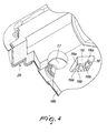
- the stroke limiter comprises a protrusion 14, which extends from at least one of the motor 4 and the generator 5 and is inserted, at least in the configuration for use, in a recess 15, which is formed inside the shell 2 (and visible in detail in Figure 4 ) and accommodates a contoured ridge 16, which extends from said shell 2.
- the protrusion 14 and the ridge 16 are provided with respective terminal prongs 14a, 16a that are spaced by corresponding grooves 14b, 16b), so as to allow the mutual shape mating between the protrusion 14 and the ridge 16 at least in the configuration for use (when the protrusion 14 is inserted in the recess 15).
- one of the protrusion 14 and the ridge 16 abuts against the prongs 14a, 16a of the other one of the protrusion 14 and the ridge 16 (as a function of the direction along which the movement occurs), in order to contain and control the stroke allowed to the motor 4 and to the generator 5 (along both directions that are parallel to the horizontal plane).
- the maximum stroke allowed to the assembly constituted by the motor 4 and the generator 5 is equal to the width of the grooves 14b, 16b that is comprised between the respective prongs 14a, 16a: any larger stroke values are prevented by the prongs 14a, 16a, which in practice define a stroke limit respectively for the ridge 16 and the protrusion 14 and therefore for the motor 4 and the generator 5 with which it is associated.
- the electric power generating set 1 comprises a contoured plate 17, which is applied externally on the motor 4 (on the side opposite to the generator 5).
- the two side-by-side lugs 7 and two mutually opposite protrusions 14 therefore extend from the plate 17 and can be inserted, at least in the configuration for use, in corresponding recesses 15 (each of which accommodates a ridge 16), which are provided inside the shell 2.
- the shell 2 is constituted substantially by a first half-shell 2a and a second half-shell 2b, which are made preferably but not exclusively of self-extinguishing polypropylene (obtained by molding), have a self-supporting function (thus avoiding the need to resort to a frame made of metal or other materials that is adapted to support the parts that compose the set 1).
- each half-shell 2a, 2b is lined internally with a respective thermal insulation layer 18a, 18b, which is made of a sound-absorbing, thermally insulating and self-extinguishing material of variable thickness, which forms a channel for the conveyance of the cooling air, particularly at the critical points.
- the receptacles 11 described above and the recesses 15 described above are thus provided in said layers 18a, 18b (obtained preferably but not exclusively by molding).
- the assembly constituted by the motor 4 and the generator 5 is simply rested on the respective supports (which are integral with the shell 2 and more particularly with the second half-shell 2b). More precisely, in the configuration for use, some useful surfaces of the motor 4, which are inclined with respect to the horizontal plane and are constituted by the lateral surfaces 8a of the conical protrusions 8, are accommodated in flared portions 9 (which are in turn conical), which form respective surface regions that are shaped complementary and are associated with the shell 2.
- the generator 5 (rigidly coupled to the motor 4) rests on the shell 2 with two faces 12 of its enclosure, which constitute additional useful surfaces and are simply rested on respective surface regions defined by the ends 13 of sleeves 10.
- the mating between the assembly constituted by the motor 4 and the generator 5 and the shell 2 is achieved, other than in known electric power generating sets, without resorting to rigid fixing elements (screws, nuts, etc.), and this allows first of all reducing or eliminating the transmission of vibrations to said shell 2, leaving said assembly free to oscillate freely.
- stroke limiters which contain and control the stroke allowed to the motor 4 and to the generator 5, contributes to the optimum centering and to avoiding the danger that the components might exit from their respective seats.
- the electric power generating set 1 automatically resumes the correct centering of the rotating elements that are present therein.
- the channels provided within the half-shells 2a, 2b are capable of utilizing the heat released by the thermal motor 4 and by the generator 5 in order to heat, where necessary, sensitive parts of the vehicle on which the set 1 is installed which are external to the cabin, such as for example the chamber for accommodating the drive unit or the wastewater drain valves.
- the electric power generating set according to the invention achieves fully the intended aim, since the use of a motor and a generator which, at least in a configuration for use, rest against the respective shell at a plurality of useful surfaces that are inclined with respect to the resting surface of said shell and are detachably rested against respective surface regions that are shaped complementary and rigidly associated with the latter, makes it possible to provide an electric power generating set that ensures correct centering with respect to the shell that contains it, without transmitting vibrations thereto during operation.
- the materials used, as well as the dimensions, may be any according to the requirements and the state of the art.
Landscapes
- Engineering & Computer Science (AREA)
- Power Engineering (AREA)
- Chemical & Material Sciences (AREA)
- Combustion & Propulsion (AREA)
- Mechanical Engineering (AREA)
- General Engineering & Computer Science (AREA)
- Connection Of Motors, Electrical Generators, Mechanical Devices, And The Like (AREA)
- Transition And Organic Metals Composition Catalysts For Addition Polymerization (AREA)
- Control Of Eletrric Generators (AREA)
- Percussion Or Vibration Massage (AREA)
- Motor Or Generator Frames (AREA)
Abstract
Description
- The present invention relates to an electric power generating set.
- Currently, vehicles such as campers, caravans, truck campers and the like are provided usually with electric power generating sets, i.e., with devices capable for example of recharging electric batteries in order to ensure correct operation of the many user devices (lighting, heating, television, refrigerator, etc.) with which said vehicles are provided.
- As is known, these sets use a motor (of the internal combustion type) and an electric power generator arranged downstream of the motor to convert the mechanical energy provided by the latter into the desired electric power.
- The assembly constituted by the motor and the generator, being provided with various rotating elements (a flywheel and a fan, for example), must be centered perfectly with respect to some physical references, such as for example the scroll of said fan (or other casing), in order to ensure optimum operation and prevent the onset of vibrations.
- For this purpose, therefore, the motor and the generator are usually fixed rigidly within a reference and protection shell with the interposition of elements (bushings or others) capable of damping vibrations.
- In practice, therefore, once installation has been completed, the electric power generating set (which in turn, as shown, is constituted by the motor and by the current generator) forms a monolithic body with the shell that accommodates it, protecting it.
- However, this constructive solution is not free from drawbacks.
- Despite resorting to elements capable of damping vibrations, it is not possible to eliminate them completely, and therefore during the operation of the set these vibrations are transmitted to the shell, causing evident unwanted effects.
- Furthermore, the need to fix rigidly the assembly composed of the motor and the generator to the shell increases significantly the complexity of the operations for assembly and installation of the generator.
- Finally, it should be noted that even after completing the assembly of the generator, the rigid connections among the various components make maintenance activities (be they periodic scheduled operations or exceptional interventions caused by malfunctions or other than unexpected events) far more awkward.
- The aim of the present invention is to solve the problems described above, providing an electric power generating set that ensures correct centering with respect to the shell that contains it without transmitting vibrations thereto during operation.
- Within this aim, an object of the invention is to provide an electric power generating set that can be assembled and installed easily.
- Another object of the invention is to provide an electric power generating set that allows performing maintenance interventions simply and easily.
- A further object of the invention is to provide an electric power generating set that maintains the correct centering of the rotating elements that are present therein even after impacts and/or overturning actions.
- Another object of the invention is to provide an electric power generating set that ensures high reliability in operation and makes it possible to optimize the utilization of the power with which it is supplied.
- Not the least object of the invention is to provide an electric power generating set that can be obtained easily starting from commonly commercially available elements and materials.
- Another object of the invention is to provide an electric power generating set that has low costs and is safe in application.
- This aim and these objects are achieved by an electric power generating set, comprising a shell that forms inside it a compartment for accommodating a motor for dispensing mechanical energy and a current generator that is coupled to said motor for the conversion of the mechanical energy delivered by said motor into electric power, to be supplied to at least one respective user device, characterized in that at least in one configuration for use said motor and said generator rest against said shell at a plurality of useful surfaces that are inclined with respect to the resting surface of said shell and are rested detachably against respective complementarily shaped surface regions that are associated rigidly with said shell, for the automatic centering and reference of said motor and said generator with respect to said shell.
- Further characteristics and advantages of the invention will become more apparent from the description of a preferred but not exclusive embodiment of the electric power generating set according to the invention, illustrated by way of non-limiting example in the accompanying drawings, wherein:
-
Figure 1 is a partially sectional and partially exploded perspective view of the electric power generating set according to the invention; -
Figure 2 is a partially sectional front elevation view of the electric power generating set ofFigure 1 ; -
Figure 3 is a schematic partially sectional front elevation view of the electric power generating set according to the invention in the configuration for use; -
Figure 4 is a highly enlarged-scale partially sectional perspective view of a detail of the electric power generating set according to the invention. - With particular reference to the cited figures, the reference numeral 1 designates generally an electric power generating set which comprises a shell 2, which forms internally an
accommodation compartment 3 for amotor 4 for delivering mechanical energy, and a current generator 5, which is coupled to themotor 4. The generator 5 can thus convert the mechanical energy delivered by themotor 4 into electric power to be supplied to at least one respective user device. - Said electric power generating set 1 can thus be used, preferably but not exclusively, in vehicles such as campers, caravans, truck campers and the like, for example to recharge user devices constituted by electric batteries, with which said vehicles are equipped, in order to ensure the correct operation of the many user devices (lighting, heating, television, refrigerator, etc.) with which they are provided.
- It is specified right now that although the use of the set 1 for vehicles such as the ones mentioned above is a preferred application of the invention, and for this reason reference will be made predominantly to it in the continuation of the present description, the use of the set 1 according to the invention in different fields of application is not excluded without thereby abandoning the protective scope claimed herein.
- The
motor 4 may be any, and can be for example any internal combustion motor, supplied with any fuel, as a function of the specific requirements; for example, with additional reference to the preferred application, themotor 4 is a two-stroke LPG-fueled engine. - The choice of this type of
motor 4 in fact ensures compact size, low noise, reduced vibrations, reliability, absence of scheduled maintenance. Furthermore, as can be deduced from the accompanying figures, in order to reduce vertical space occupation themotor 4 is arranged so that its cylinder 6 is in a horizontal position. - The generator 5 can be an alternator, but in the preferred application it is constituted by a dynamo. This solution makes it possible to have direct current directly at the output, without the need to interpose a rectifier, thus making available, in a relatively simple manner, a powerful electric driver to be used also to start the electric power generating set 1 itself, without having to resort to a traditional starter motor, thus achieving a reduction in space occupation, weight and costs and a mechanical and electrical simplification.
- According to the invention, the
motor 4 and the generator 5 rest against the shell 2, at least in a configuration for use (shown inFigure 3 ), at a plurality of useful surfaces, which are inclined with respect to the resting surface of the shell 2 (and therefore with respect to a horizontal plane). - More precisely, such useful surfaces are rested detachably on respective surface regions that are shaped complementarily and are associated rigidly with the shell 2: in this manner it is possible to obtain automatically by gravity the centering and reference of the
motor 4 and of the generator 5 with respect to the shell 2. - Since there is furthermore no rigid connection between the shell 2 and the assembly constituted by the
motor 4 and the generator 5 (which are kept centered thanks to the particular coupling method described above), any vibrations of this assembly are not transmitted to the shell 2, thus achieving already the intended aim. - In particular, the electric power generating set 1 comprises at least one
lug 7, which protrudes from at least one of themotor 4 and the generator 5 and has at least oneconical protrusion 8. - It is indeed the
lateral surface 8a of theprotrusion 8 that constitutes at least one of said useful surfaces, since it is accommodated detachably, at least in the configuration for use, in a respectiveflared receptacle 9, which is associated rigidly with the shell 2 and in turn constitutes at least one of the surface regions. - More particularly, in a constructive solution of considerable practical interest, proposed in the accompanying figures by way of non-limiting example of the application of the invention, the electric power generating set 1 comprises two
lugs 7 that are mutually side-by-side, extend from themotor 4 and have respectiveconical protrusions 8. - The
lateral surface 8a of eachprotrusion 8 thus constitutes a respective useful surface, which is accommodated detachably, at least in the configuration for use, in the correspondingflared receptacle 9; in turn, eachreceptacle 9 is associated rigidly with the shell 2 and constitutes one of the surface regions described above. - Usefully, in the preferred constructive solution, which does not limit the application of the invention, each
receptacle 9 is provided in an end portion of a respective substantiallycylindrical sleeve 10, which is made of a vibration-damping material and is coupled stably to acorresponding receptacle 11, shaped by the shell 2. - In practice, therefore, the two protrusions 8 (one for each lug 7) are accommodated in
respective receptacles 9, provided in twosleeves 10 that are arranged along vertical axes (and are therefore mutually parallel). - Conveniently, at least one of the
motor 4 and the generator 5 has an external enclosure that is at least partially prism-shaped: two of theflat faces 12 of said enclosure can thus constitute additional respective useful surfaces, which are rested detachably and stably, at least in the configuration for use, on respective oppositely inclined (i.e., converging) surface regions that have a complementary shape and are associated rigidly with the shell 2. - More particularly, as is evident from
Figure 2 , in the preferred constructive solution it is the generator 5 that has a partially prism-shaped external enclosure with an octagonal base (more precisely, the enclosure has a first portion with a cylindrical shape, which faces themotor 4, and a second portion that has an octagonal prism-like shape). In this manner, the twoflat faces 12 cited above can rest detachably and stably, at least in the configuration for use, onrespective ends 13 of other substantiallycylindrical sleeves 10, saidends 13 thus constituting additional corresponding surface regions. - The
sleeves 10 can be of the type described above, and thus be made of a vibration-damping material, and are coupled stably to correspondingadditional receptacles 11, which are shaped by the shell 2 and are arranged, in this case, along axes that are oppositely inclined (perpendicular to therespective faces 12 of the enclosure of the generator 5). - Advantageously, the electric power generating set 1 comprises at least one stroke limiter, in order to contain and control the stroke allowed to the
motor 4 and to the generator 5 (since, as shown, they only rest against the shell 2 without being stably anchored thereto). - In particular, in the constructive solution proposed merely by way of example in the accompanying figures, the stroke limiter comprises a
protrusion 14, which extends from at least one of themotor 4 and the generator 5 and is inserted, at least in the configuration for use, in arecess 15, which is formed inside the shell 2 (and visible in detail inFigure 4 ) and accommodates acontoured ridge 16, which extends from said shell 2. - As shown clearly by figures
Figures 2 ,3 and4 , theprotrusion 14 and theridge 16 are provided with respectiveterminal prongs corresponding grooves protrusion 14 and theridge 16 at least in the configuration for use (when theprotrusion 14 is inserted in the recess 15). - Thus, upon a stroke of the
motor 4 and of the generator 5 beyond a predefined value, one of theprotrusion 14 and theridge 16 abuts against theprongs protrusion 14 and the ridge 16 (as a function of the direction along which the movement occurs), in order to contain and control the stroke allowed to themotor 4 and to the generator 5 (along both directions that are parallel to the horizontal plane). - In fact, it is evident that the maximum stroke allowed to the assembly constituted by the
motor 4 and the generator 5 (mutually rigidly coupled) is equal to the width of thegrooves respective prongs prongs ridge 16 and theprotrusion 14 and therefore for themotor 4 and the generator 5 with which it is associated. - Even more particularly, and with reference to the constructive solution proposed in the accompanying figures by way of non-limiting example, the electric power generating set 1 comprises a
contoured plate 17, which is applied externally on the motor 4 (on the side opposite to the generator 5). - The two side-by-
side lugs 7 and two mutuallyopposite protrusions 14 therefore extend from theplate 17 and can be inserted, at least in the configuration for use, in corresponding recesses 15 (each of which accommodates a ridge 16), which are provided inside the shell 2. - Positively, the shell 2 is constituted substantially by a first half-
shell 2a and a second half-shell 2b, which are made preferably but not exclusively of self-extinguishing polypropylene (obtained by molding), have a self-supporting function (thus avoiding the need to resort to a frame made of metal or other materials that is adapted to support the parts that compose the set 1). - It should be noted that it is possible to provide on the half-
shells - Furthermore, each half-
shell thermal insulation layer receptacles 11 described above and therecesses 15 described above are thus provided in saidlayers - Operation of the electric power generating set according to the invention is as follows.
- As shown, in the electric power generating set 1 the assembly constituted by the
motor 4 and the generator 5 is simply rested on the respective supports (which are integral with the shell 2 and more particularly with the second half-shell 2b). More precisely, in the configuration for use, some useful surfaces of themotor 4, which are inclined with respect to the horizontal plane and are constituted by thelateral surfaces 8a of theconical protrusions 8, are accommodated in flared portions 9 (which are in turn conical), which form respective surface regions that are shaped complementary and are associated with the shell 2. - Furthermore, the generator 5 (rigidly coupled to the motor 4) rests on the shell 2 with two
faces 12 of its enclosure, which constitute additional useful surfaces and are simply rested on respective surface regions defined by theends 13 ofsleeves 10. - Therefore, the mating between the assembly constituted by the
motor 4 and the generator 5 and the shell 2 is achieved, other than in known electric power generating sets, without resorting to rigid fixing elements (screws, nuts, etc.), and this allows first of all reducing or eliminating the transmission of vibrations to said shell 2, leaving said assembly free to oscillate freely. - The choice to rest the
motor 4 and the generator 5 on sleeves 10 (which respectively have the flaredportions 9 that accommodate theprotrusions 8 and theends 13 on which thefaces 12 rest) made of vibration-damping material also contributes to this result. - At the same time, the correct centering of the various components (for example of the
fan 5a of the generator 5) with respect to references that are integral with the shell 2 (for example thescroll 2c that accommodates it) is ensured by the choice to rest themotor 4 and the generator 5 against the shell 2 at useful surfaces that are inclined (with respect to the resting surface of said shell 2) and abut, as shown, against respective surface regions that are shaped complementary. - In fact, if, during assembly (or due to impacts, vibrations, oscillations, etc.) a misalignment between the parts occurs due to gravity (and therefore automatically), the useful surfaces slide on the surface regions until they move or return to the optimum position defined by design, which corresponds to the correct centering and reference of the
motor 4 and of the generator 5 with respect to the shell 2. - This ensures, therefore, optimum operation as well as an additional effect that is favorable to vibration containment.
- As shown, the use of stroke limiters, which contain and control the stroke allowed to the
motor 4 and to the generator 5, contributes to the optimum centering and to avoiding the danger that the components might exit from their respective seats. - Moreover, for the reasons described above, if an overturning or tipping of the set 1 occurs, once the correct horizontal position (and therefore the configuration for use) has been restored, the electric power generating set 1 automatically resumes the correct centering of the rotating elements that are present therein.
- Moreover, it should be noted that the lack of rigid couplings between the shell 2 and the assembly constituted by the
motor 4 and the generator 5, which are simply rested on the second half-shell 2b, allows of course a considerable simplification of the operations for the assembly and installation of the set 1 according to the invention and facilitates considerably its maintenance operations. - Finally, it is specified that the channels provided within the half-
shells thermal motor 4 and by the generator 5 in order to heat, where necessary, sensitive parts of the vehicle on which the set 1 is installed which are external to the cabin, such as for example the chamber for accommodating the drive unit or the wastewater drain valves. - This allows using, at least partially, the amount of energy that otherwise would be dispersed by the
motor 4, which, as is known, is able to deliver and make available to thegenerator 5 a quantity of mechanical energy that is only a minimum fraction of the energy with which it is supplied. - In practice it has been found that the electric power generating set according to the invention achieves fully the intended aim, since the use of a motor and a generator which, at least in a configuration for use, rest against the respective shell at a plurality of useful surfaces that are inclined with respect to the resting surface of said shell and are detachably rested against respective surface regions that are shaped complementary and rigidly associated with the latter, makes it possible to provide an electric power generating set that ensures correct centering with respect to the shell that contains it, without transmitting vibrations thereto during operation.
- The invention thus conceived is susceptible of numerous modifications and variations, all of which are within the scope of the appended claims; all the details may furthermore be replaced with other technically equivalent elements.
- In the exemplary embodiment shown, individual characteristics, given in relation to specific examples, may actually be interchanged with other different characteristics that exist in other exemplary embodiments.
- In practice, the materials used, as well as the dimensions, may be any according to the requirements and the state of the art.
- The disclosures in Italian Patent Application No.
BO2013A00553 - Where technical features mentioned in any claim are followed by reference signs, those reference signs have been included for the sole purpose of increasing the intelligibility of the claims and accordingly such reference signs do not have any limiting effect on the interpretation of each element identified by way of example by such reference signs.
Claims (10)
- An electric power generating set, comprising a shell (2) that forms internally an accommodation compartment (3) for a motor (4) for delivering mechanical energy, and a current generator (5), which is coupled to said motor (4), for converting the mechanical energy delivered by said motor (4) into electric power, to be supplied to at least one respective user device, characterized in that, at least in one configuration for use, said motor (4) and said generator (5) rest on said shell (2) at a plurality of useful surfaces, which are inclined with respect to the resting surface of said shell (2) and rest detachably on respective surface regions that are shaped complementary and are associated rigidly with said shell (2) for the automatic centering and reference of said motor (4) and of said generator (5) with respect to said shell (2).
- The electric power generating set according to claim 1, characterized in that it comprises at least one lug (7) that extends from at least one of said motor (4) and said generator (5), said lug (7) having at least one conical protrusion (8), the lateral surface (8a) of said protrusion (8) constituting at least one of said useful surfaces, which is accommodated detachably, at least in said configuration for use, in a respective flared receptacle (9), which is associated rigidly with said shell (2) and constitutes at least one of said surface regions.
- The electric power generating set according to claim 2, characterized in that it comprises two of said lugs (7) which are arranged mutually side by side, extend from said motor (4) and have said respective conical protrusions (8), the lateral surface (8a) of each one of said protrusions (8) constituting a respective useful surface, which is accommodated detachably, at least in said configuration for use, in a corresponding flared receptacle (9), which is associated rigidly with said shell (2) and constitutes one of said surface regions.
- The electric power generating set according to one or more of the preceding claims, characterized in that each one of said receptacles (9) is provided in an end portion of a respective substantially cylindrical sleeve (10), made of a vibration-damping material, which is coupled stably to a corresponding receptacle (11) that is formed by said shell (2).
- The electric power generating set according to claim 1, characterized in that at least one of said motor (4) and said generator (5) has an external enclosure that is at least partially prism-shaped, two of the flat faces (12) of said enclosure constituting said respective useful surfaces, which rest detachably and stably, at least in said configuration for use, on respective oppositely inclined and complementary shaped surface regions that are rigidly associated with said shell (2).
- The electric power generating set according to claim 5, characterized in that said generator (5) has a partially prism-like external enclosure with an octagonal base, said two flat faces (12) of said enclosure resting stably and detachably, at least in said configuration for use, on respective ends (13), which constitute said surface regions, of substantially cylindrical sleeves (10), made of a vibration-damping material, which are coupled stably to corresponding receptacles (11) that are shaped by said shell (2) and are arranged along oppositely inclined axes.
- The electric power generating set according to one or more of the preceding claims, characterized in that it comprises at least one stroke limiter for containing and controlling the stroke allowed to said motor (4) and to said generator (5).
- The electric power generating set according to claim 7, characterized in that said at least one stroke limiter comprises a protrusion (14), which extends from at least one of said motor (4) and said generator (5) and is inserted, at least in said configuration for use, in a recess (15) that is provided inside said shell (2) and accommodates a contoured ridge (16), which extends from said shell (2), said protrusion (14) and said ridge (16) having respective terminal prongs (14a, 16a) that are spaced by corresponding grooves (14b, 16b) for mutual shape mating between said protrusion (14) and said ridge (16) at least in said configuration for use, at a stroke of said motor (4) and of said generator (5) beyond a preset value, one of said protrusion (14) and said ridge (16) abutting against said prongs (14a, 16a) of the other one of said protrusion (14) and said ridge (16), in order to contain and control the stroke allowed to said motor (4) and to said generator (5).
- The electric power generating set according to one or more of the preceding claims, characterized in that it comprises a contoured plate (17), which is applied externally on said motor (4), said two side-by-side lugs (7) and two of said mutually opposite protrusions (14), inserted, at least in said configuration for use, in said corresponding recesses (15) provided inside said shell (2), protruding from said plate (17).
- The electric power generating set according to one or more of the preceding claims, characterized in that said shell (2) is constituted substantially by a first half-shell (2a) and a second half-shell (2b), each one of said half-shells (2a, 2b) being lined internally by a respective thermal insulation layer (18a, 18b), made of a self-extinguishing, soundproofing and thermally insulating material and forming a channel for the conveyance of the cooling air, said receptacles (11) and said recesses (15) being provided in said layers (18a, 18b).
Applications Claiming Priority (1)
| Application Number | Priority Date | Filing Date | Title |
|---|---|---|---|
| IT000553A ITBO20130553A1 (en) | 2013-10-09 | 2013-10-09 | GENERATOR GROUP |
Publications (2)
| Publication Number | Publication Date |
|---|---|
| EP2866329A1 true EP2866329A1 (en) | 2015-04-29 |
| EP2866329B1 EP2866329B1 (en) | 2019-12-04 |
Family
ID=49725186
Family Applications (1)
| Application Number | Title | Priority Date | Filing Date |
|---|---|---|---|
| EP14187707.6A Active EP2866329B1 (en) | 2013-10-09 | 2014-10-06 | Electric power generating set |
Country Status (3)
| Country | Link |
|---|---|
| EP (1) | EP2866329B1 (en) |
| CN (1) | CN104578580B (en) |
| IT (1) | ITBO20130553A1 (en) |
Citations (3)
| Publication number | Priority date | Publication date | Assignee | Title |
|---|---|---|---|---|
| JPH09217632A (en) * | 1996-02-14 | 1997-08-19 | Denyo Kk | Pipe-shaped frame structure of engine driven generator |
| JP2004011490A (en) * | 2002-06-05 | 2004-01-15 | Yanmar Co Ltd | Power generating device |
| EP1666785A1 (en) * | 2003-09-09 | 2006-06-07 | HONDA MOTOR CO., Ltd. | Engine-driven working machine |
Family Cites Families (1)
| Publication number | Priority date | Publication date | Assignee | Title |
|---|---|---|---|---|
| CN101320890A (en) * | 2008-02-03 | 2008-12-10 | 科泰电源设备(上海)有限公司 | Combination type low noise square compartment power station |
-
2013
- 2013-10-09 IT IT000553A patent/ITBO20130553A1/en unknown
-
2014
- 2014-10-06 EP EP14187707.6A patent/EP2866329B1/en active Active
- 2014-10-09 CN CN201410528448.0A patent/CN104578580B/en active Active
Patent Citations (3)
| Publication number | Priority date | Publication date | Assignee | Title |
|---|---|---|---|---|
| JPH09217632A (en) * | 1996-02-14 | 1997-08-19 | Denyo Kk | Pipe-shaped frame structure of engine driven generator |
| JP2004011490A (en) * | 2002-06-05 | 2004-01-15 | Yanmar Co Ltd | Power generating device |
| EP1666785A1 (en) * | 2003-09-09 | 2006-06-07 | HONDA MOTOR CO., Ltd. | Engine-driven working machine |
Also Published As
| Publication number | Publication date |
|---|---|
| ITBO20130553A1 (en) | 2015-04-10 |
| EP2866329B1 (en) | 2019-12-04 |
| CN104578580A (en) | 2015-04-29 |
| CN104578580B (en) | 2018-08-28 |
Similar Documents
| Publication | Publication Date | Title |
|---|---|---|
| JP5899446B2 (en) | Contactless power supply | |
| US20220281288A1 (en) | Systems and methods for disconnecting a dc load from a dc power source | |
| US20150236315A1 (en) | Fixing battery cells in place by compressed cell fixture | |
| RU2685504C2 (en) | Electrical energy storage device | |
| FR2924857B1 (en) | ELECTRICAL SUPPLY DEVICE COMPRISING A RECEPTION UNIT FOR ULTRA CAPACITY STORAGE UNITS | |
| EP1447541B1 (en) | Engine generator | |
| JP6404270B2 (en) | Mounting structure of electronic component storage box | |
| EP2803519B1 (en) | Electrical power generating engine flywheel with active torque control | |
| KR20160122919A (en) | Transformer for obc of electric vehicle | |
| CN108691707A (en) | Generator of engine | |
| EP2866329B1 (en) | Electric power generating set | |
| JP2009283297A (en) | Terminal block structure | |
| US20130213182A1 (en) | Arrangement for an internal combustion engine | |
| US9444304B2 (en) | Generator set having adjustable terminal box | |
| US20250207528A1 (en) | Hybrid Motor for Fluid Pump | |
| KR102363983B1 (en) | Structure of electric power train for elelctric vehicle | |
| FR3027854A1 (en) | ELECTRICAL CONNECTION CABLE FOR CHARGING AN ENERGY ACCUMULATOR OF A MOTOR VEHICLE | |
| US9435313B2 (en) | Starter arrangement | |
| JP2016220470A (en) | Power equipment | |
| JP5590408B2 (en) | Combined structure of electrical junction box and electrical unit | |
| US20180366963A1 (en) | Charging socket mounting assembly | |
| US9548694B2 (en) | Power generator unit for a vehicle | |
| JP6833154B1 (en) | Charge / discharge device | |
| KR200156210Y1 (en) | Out-put terminal of vehicle for alternator | |
| WO2026032824A1 (en) | Battery operated power unit and method for supplying power to external equipment |
Legal Events
| Date | Code | Title | Description |
|---|---|---|---|
| PUAI | Public reference made under article 153(3) epc to a published international application that has entered the european phase |
Free format text: ORIGINAL CODE: 0009012 |
|
| 17P | Request for examination filed |
Effective date: 20141006 |
|
| AK | Designated contracting states |
Kind code of ref document: A1 Designated state(s): AL AT BE BG CH CY CZ DE DK EE ES FI FR GB GR HR HU IE IS IT LI LT LU LV MC MK MT NL NO PL PT RO RS SE SI SK SM TR |
|
| AX | Request for extension of the european patent |
Extension state: BA ME |
|
| R17P | Request for examination filed (corrected) |
Effective date: 20150827 |
|
| RBV | Designated contracting states (corrected) |
Designated state(s): AL AT BE BG CH CY CZ DE DK EE ES FI FR GB GR HR HU IE IS IT LI LT LU LV MC MK MT NL NO PL PT RO RS SE SI SK SM TR |
|
| GRAP | Despatch of communication of intention to grant a patent |
Free format text: ORIGINAL CODE: EPIDOSNIGR1 |
|
| STAA | Information on the status of an ep patent application or granted ep patent |
Free format text: STATUS: GRANT OF PATENT IS INTENDED |
|
| RIC1 | Information provided on ipc code assigned before grant |
Ipc: F02B 63/04 20060101ALI20190528BHEP Ipc: H02K 7/18 20060101ALN20190528BHEP Ipc: H02K 15/16 20060101ALN20190528BHEP Ipc: H02K 5/24 20060101AFI20190528BHEP |
|
| INTG | Intention to grant announced |
Effective date: 20190621 |
|
| RIN1 | Information on inventor provided before grant (corrected) |
Inventor name: FABBRI, RAUL |
|
| GRAS | Grant fee paid |
Free format text: ORIGINAL CODE: EPIDOSNIGR3 |
|
| GRAA | (expected) grant |
Free format text: ORIGINAL CODE: 0009210 |
|
| STAA | Information on the status of an ep patent application or granted ep patent |
Free format text: STATUS: THE PATENT HAS BEEN GRANTED |
|
| AK | Designated contracting states |
Kind code of ref document: B1 Designated state(s): AL AT BE BG CH CY CZ DE DK EE ES FI FR GB GR HR HU IE IS IT LI LT LU LV MC MK MT NL NO PL PT RO RS SE SI SK SM TR |
|
| REG | Reference to a national code |
Ref country code: GB Ref legal event code: FG4D |
|
| REG | Reference to a national code |
Ref country code: CH Ref legal event code: EP |
|
| REG | Reference to a national code |
Ref country code: AT Ref legal event code: REF Ref document number: 1210653 Country of ref document: AT Kind code of ref document: T Effective date: 20191215 |
|
| REG | Reference to a national code |
Ref country code: DE Ref legal event code: R096 Ref document number: 602014057720 Country of ref document: DE |
|
| REG | Reference to a national code |
Ref country code: IE Ref legal event code: FG4D |
|
| REG | Reference to a national code |
Ref country code: NL Ref legal event code: MP Effective date: 20191204 |
|
| REG | Reference to a national code |
Ref country code: LT Ref legal event code: MG4D |
|
| PG25 | Lapsed in a contracting state [announced via postgrant information from national office to epo] |
Ref country code: LT Free format text: LAPSE BECAUSE OF FAILURE TO SUBMIT A TRANSLATION OF THE DESCRIPTION OR TO PAY THE FEE WITHIN THE PRESCRIBED TIME-LIMIT Effective date: 20191204 Ref country code: ES Free format text: LAPSE BECAUSE OF FAILURE TO SUBMIT A TRANSLATION OF THE DESCRIPTION OR TO PAY THE FEE WITHIN THE PRESCRIBED TIME-LIMIT Effective date: 20191204 Ref country code: SE Free format text: LAPSE BECAUSE OF FAILURE TO SUBMIT A TRANSLATION OF THE DESCRIPTION OR TO PAY THE FEE WITHIN THE PRESCRIBED TIME-LIMIT Effective date: 20191204 Ref country code: LV Free format text: LAPSE BECAUSE OF FAILURE TO SUBMIT A TRANSLATION OF THE DESCRIPTION OR TO PAY THE FEE WITHIN THE PRESCRIBED TIME-LIMIT Effective date: 20191204 Ref country code: GR Free format text: LAPSE BECAUSE OF FAILURE TO SUBMIT A TRANSLATION OF THE DESCRIPTION OR TO PAY THE FEE WITHIN THE PRESCRIBED TIME-LIMIT Effective date: 20200305 Ref country code: FI Free format text: LAPSE BECAUSE OF FAILURE TO SUBMIT A TRANSLATION OF THE DESCRIPTION OR TO PAY THE FEE WITHIN THE PRESCRIBED TIME-LIMIT Effective date: 20191204 Ref country code: NO Free format text: LAPSE BECAUSE OF FAILURE TO SUBMIT A TRANSLATION OF THE DESCRIPTION OR TO PAY THE FEE WITHIN THE PRESCRIBED TIME-LIMIT Effective date: 20200304 Ref country code: BG Free format text: LAPSE BECAUSE OF FAILURE TO SUBMIT A TRANSLATION OF THE DESCRIPTION OR TO PAY THE FEE WITHIN THE PRESCRIBED TIME-LIMIT Effective date: 20200304 |
|
| PG25 | Lapsed in a contracting state [announced via postgrant information from national office to epo] |
Ref country code: RS Free format text: LAPSE BECAUSE OF FAILURE TO SUBMIT A TRANSLATION OF THE DESCRIPTION OR TO PAY THE FEE WITHIN THE PRESCRIBED TIME-LIMIT Effective date: 20191204 Ref country code: HR Free format text: LAPSE BECAUSE OF FAILURE TO SUBMIT A TRANSLATION OF THE DESCRIPTION OR TO PAY THE FEE WITHIN THE PRESCRIBED TIME-LIMIT Effective date: 20191204 |
|
| PG25 | Lapsed in a contracting state [announced via postgrant information from national office to epo] |
Ref country code: AL Free format text: LAPSE BECAUSE OF FAILURE TO SUBMIT A TRANSLATION OF THE DESCRIPTION OR TO PAY THE FEE WITHIN THE PRESCRIBED TIME-LIMIT Effective date: 20191204 |
|
| PG25 | Lapsed in a contracting state [announced via postgrant information from national office to epo] |
Ref country code: RO Free format text: LAPSE BECAUSE OF FAILURE TO SUBMIT A TRANSLATION OF THE DESCRIPTION OR TO PAY THE FEE WITHIN THE PRESCRIBED TIME-LIMIT Effective date: 20191204 Ref country code: NL Free format text: LAPSE BECAUSE OF FAILURE TO SUBMIT A TRANSLATION OF THE DESCRIPTION OR TO PAY THE FEE WITHIN THE PRESCRIBED TIME-LIMIT Effective date: 20191204 Ref country code: CZ Free format text: LAPSE BECAUSE OF FAILURE TO SUBMIT A TRANSLATION OF THE DESCRIPTION OR TO PAY THE FEE WITHIN THE PRESCRIBED TIME-LIMIT Effective date: 20191204 Ref country code: EE Free format text: LAPSE BECAUSE OF FAILURE TO SUBMIT A TRANSLATION OF THE DESCRIPTION OR TO PAY THE FEE WITHIN THE PRESCRIBED TIME-LIMIT Effective date: 20191204 Ref country code: PT Free format text: LAPSE BECAUSE OF FAILURE TO SUBMIT A TRANSLATION OF THE DESCRIPTION OR TO PAY THE FEE WITHIN THE PRESCRIBED TIME-LIMIT Effective date: 20200429 |
|
| PG25 | Lapsed in a contracting state [announced via postgrant information from national office to epo] |
Ref country code: SK Free format text: LAPSE BECAUSE OF FAILURE TO SUBMIT A TRANSLATION OF THE DESCRIPTION OR TO PAY THE FEE WITHIN THE PRESCRIBED TIME-LIMIT Effective date: 20191204 Ref country code: IS Free format text: LAPSE BECAUSE OF FAILURE TO SUBMIT A TRANSLATION OF THE DESCRIPTION OR TO PAY THE FEE WITHIN THE PRESCRIBED TIME-LIMIT Effective date: 20200404 Ref country code: SM Free format text: LAPSE BECAUSE OF FAILURE TO SUBMIT A TRANSLATION OF THE DESCRIPTION OR TO PAY THE FEE WITHIN THE PRESCRIBED TIME-LIMIT Effective date: 20191204 |
|
| REG | Reference to a national code |
Ref country code: DE Ref legal event code: R097 Ref document number: 602014057720 Country of ref document: DE |
|
| REG | Reference to a national code |
Ref country code: AT Ref legal event code: MK05 Ref document number: 1210653 Country of ref document: AT Kind code of ref document: T Effective date: 20191204 |
|
| PLBE | No opposition filed within time limit |
Free format text: ORIGINAL CODE: 0009261 |
|
| STAA | Information on the status of an ep patent application or granted ep patent |
Free format text: STATUS: NO OPPOSITION FILED WITHIN TIME LIMIT |
|
| PG25 | Lapsed in a contracting state [announced via postgrant information from national office to epo] |
Ref country code: DK Free format text: LAPSE BECAUSE OF FAILURE TO SUBMIT A TRANSLATION OF THE DESCRIPTION OR TO PAY THE FEE WITHIN THE PRESCRIBED TIME-LIMIT Effective date: 20191204 |
|
| 26N | No opposition filed |
Effective date: 20200907 |
|
| PG25 | Lapsed in a contracting state [announced via postgrant information from national office to epo] |
Ref country code: SI Free format text: LAPSE BECAUSE OF FAILURE TO SUBMIT A TRANSLATION OF THE DESCRIPTION OR TO PAY THE FEE WITHIN THE PRESCRIBED TIME-LIMIT Effective date: 20191204 Ref country code: AT Free format text: LAPSE BECAUSE OF FAILURE TO SUBMIT A TRANSLATION OF THE DESCRIPTION OR TO PAY THE FEE WITHIN THE PRESCRIBED TIME-LIMIT Effective date: 20191204 Ref country code: PL Free format text: LAPSE BECAUSE OF FAILURE TO SUBMIT A TRANSLATION OF THE DESCRIPTION OR TO PAY THE FEE WITHIN THE PRESCRIBED TIME-LIMIT Effective date: 20191204 |
|
| REG | Reference to a national code |
Ref country code: CH Ref legal event code: PL |
|
| PG25 | Lapsed in a contracting state [announced via postgrant information from national office to epo] |
Ref country code: LU Free format text: LAPSE BECAUSE OF NON-PAYMENT OF DUE FEES Effective date: 20201006 Ref country code: MC Free format text: LAPSE BECAUSE OF FAILURE TO SUBMIT A TRANSLATION OF THE DESCRIPTION OR TO PAY THE FEE WITHIN THE PRESCRIBED TIME-LIMIT Effective date: 20191204 |
|
| REG | Reference to a national code |
Ref country code: BE Ref legal event code: MM Effective date: 20201031 |
|
| PG25 | Lapsed in a contracting state [announced via postgrant information from national office to epo] |
Ref country code: BE Free format text: LAPSE BECAUSE OF NON-PAYMENT OF DUE FEES Effective date: 20201031 Ref country code: CH Free format text: LAPSE BECAUSE OF NON-PAYMENT OF DUE FEES Effective date: 20201031 Ref country code: LI Free format text: LAPSE BECAUSE OF NON-PAYMENT OF DUE FEES Effective date: 20201031 |
|
| PG25 | Lapsed in a contracting state [announced via postgrant information from national office to epo] |
Ref country code: IE Free format text: LAPSE BECAUSE OF NON-PAYMENT OF DUE FEES Effective date: 20201006 |
|
| PG25 | Lapsed in a contracting state [announced via postgrant information from national office to epo] |
Ref country code: TR Free format text: LAPSE BECAUSE OF FAILURE TO SUBMIT A TRANSLATION OF THE DESCRIPTION OR TO PAY THE FEE WITHIN THE PRESCRIBED TIME-LIMIT Effective date: 20191204 Ref country code: MT Free format text: LAPSE BECAUSE OF FAILURE TO SUBMIT A TRANSLATION OF THE DESCRIPTION OR TO PAY THE FEE WITHIN THE PRESCRIBED TIME-LIMIT Effective date: 20191204 Ref country code: CY Free format text: LAPSE BECAUSE OF FAILURE TO SUBMIT A TRANSLATION OF THE DESCRIPTION OR TO PAY THE FEE WITHIN THE PRESCRIBED TIME-LIMIT Effective date: 20191204 |
|
| PG25 | Lapsed in a contracting state [announced via postgrant information from national office to epo] |
Ref country code: MK Free format text: LAPSE BECAUSE OF FAILURE TO SUBMIT A TRANSLATION OF THE DESCRIPTION OR TO PAY THE FEE WITHIN THE PRESCRIBED TIME-LIMIT Effective date: 20191204 |
|
| P01 | Opt-out of the competence of the unified patent court (upc) registered |
Effective date: 20230527 |
|
| PGFP | Annual fee paid to national office [announced via postgrant information from national office to epo] |
Ref country code: IT Payment date: 20240920 Year of fee payment: 11 |
|
| PGFP | Annual fee paid to national office [announced via postgrant information from national office to epo] |
Ref country code: DE Payment date: 20241021 Year of fee payment: 11 |
|
| PGFP | Annual fee paid to national office [announced via postgrant information from national office to epo] |
Ref country code: GB Payment date: 20241023 Year of fee payment: 11 |
|
| PGFP | Annual fee paid to national office [announced via postgrant information from national office to epo] |
Ref country code: FR Payment date: 20241021 Year of fee payment: 11 |