EP2865934A1 - Internal combustion engine and separator structure thereof - Google Patents
Internal combustion engine and separator structure thereof Download PDFInfo
- Publication number
- EP2865934A1 EP2865934A1 EP20140188962 EP14188962A EP2865934A1 EP 2865934 A1 EP2865934 A1 EP 2865934A1 EP 20140188962 EP20140188962 EP 20140188962 EP 14188962 A EP14188962 A EP 14188962A EP 2865934 A1 EP2865934 A1 EP 2865934A1
- Authority
- EP
- European Patent Office
- Prior art keywords
- separator
- cylinder block
- auxiliary machinery
- gas
- blow
- Prior art date
- Legal status (The legal status is an assumption and is not a legal conclusion. Google has not performed a legal analysis and makes no representation as to the accuracy of the status listed.)
- Granted
Links
- 238000002485 combustion reaction Methods 0.000 title claims abstract description 56
- 239000011800 void material Substances 0.000 claims abstract description 136
- 238000000926 separation method Methods 0.000 claims abstract description 43
- 239000007788 liquid Substances 0.000 claims abstract description 27
- 238000003860 storage Methods 0.000 claims description 56
- 239000002826 coolant Substances 0.000 claims description 53
- 239000003921 oil Substances 0.000 description 130
- XLYOFNOQVPJJNP-UHFFFAOYSA-N water Chemical compound O XLYOFNOQVPJJNP-UHFFFAOYSA-N 0.000 description 58
- 230000035515 penetration Effects 0.000 description 27
- 238000009833 condensation Methods 0.000 description 24
- 230000005494 condensation Effects 0.000 description 24
- 239000003595 mist Substances 0.000 description 23
- 230000000694 effects Effects 0.000 description 16
- 238000009413 insulation Methods 0.000 description 16
- 230000000717 retained effect Effects 0.000 description 12
- 239000010419 fine particle Substances 0.000 description 8
- 239000011347 resin Substances 0.000 description 8
- 229920005989 resin Polymers 0.000 description 8
- 239000011810 insulating material Substances 0.000 description 7
- 239000000463 material Substances 0.000 description 7
- 238000004891 communication Methods 0.000 description 5
- 239000012809 cooling fluid Substances 0.000 description 5
- 238000001816 cooling Methods 0.000 description 4
- 230000003247 decreasing effect Effects 0.000 description 4
- 239000006260 foam Substances 0.000 description 4
- 230000001151 other effect Effects 0.000 description 4
- 230000000149 penetrating effect Effects 0.000 description 4
- 230000002528 anti-freeze Effects 0.000 description 3
- 239000003795 chemical substances by application Substances 0.000 description 3
- 239000012530 fluid Substances 0.000 description 3
- 238000010438 heat treatment Methods 0.000 description 3
- 230000005764 inhibitory process Effects 0.000 description 3
- 238000004519 manufacturing process Methods 0.000 description 3
- 229910052751 metal Inorganic materials 0.000 description 3
- 239000002184 metal Substances 0.000 description 3
- 238000000034 method Methods 0.000 description 3
- 239000010705 motor oil Substances 0.000 description 3
- 229910000838 Al alloy Inorganic materials 0.000 description 2
- 238000004378 air conditioning Methods 0.000 description 2
- 230000005540 biological transmission Effects 0.000 description 2
- 238000007599 discharging Methods 0.000 description 2
- 229920001971 elastomer Polymers 0.000 description 2
- 239000007791 liquid phase Substances 0.000 description 2
- 230000014759 maintenance of location Effects 0.000 description 2
- 239000000203 mixture Substances 0.000 description 2
- 230000002829 reductive effect Effects 0.000 description 2
- 238000003466 welding Methods 0.000 description 2
- 239000004215 Carbon black (E152) Substances 0.000 description 1
- 238000005260 corrosion Methods 0.000 description 1
- 230000007797 corrosion Effects 0.000 description 1
- 238000005536 corrosion prevention Methods 0.000 description 1
- 230000007423 decrease Effects 0.000 description 1
- 238000010586 diagram Methods 0.000 description 1
- 239000000446 fuel Substances 0.000 description 1
- 239000011491 glass wool Substances 0.000 description 1
- 229930195733 hydrocarbon Natural products 0.000 description 1
- 150000002430 hydrocarbons Chemical class 0.000 description 1
- -1 i.e. Substances 0.000 description 1
- 230000002401 inhibitory effect Effects 0.000 description 1
- 230000001788 irregular Effects 0.000 description 1
- 230000013011 mating Effects 0.000 description 1
- 238000000465 moulding Methods 0.000 description 1
- 239000002245 particle Substances 0.000 description 1
- 238000005192 partition Methods 0.000 description 1
- 230000002093 peripheral effect Effects 0.000 description 1
- 238000005086 pumping Methods 0.000 description 1
- 238000011084 recovery Methods 0.000 description 1
- 238000007789 sealing Methods 0.000 description 1
- 229920002803 thermoplastic polyurethane Polymers 0.000 description 1
- 238000009423 ventilation Methods 0.000 description 1
- 238000010792 warming Methods 0.000 description 1
- 239000013585 weight reducing agent Substances 0.000 description 1
Images




Classifications
-
- F—MECHANICAL ENGINEERING; LIGHTING; HEATING; WEAPONS; BLASTING
- F01—MACHINES OR ENGINES IN GENERAL; ENGINE PLANTS IN GENERAL; STEAM ENGINES
- F01M—LUBRICATING OF MACHINES OR ENGINES IN GENERAL; LUBRICATING INTERNAL COMBUSTION ENGINES; CRANKCASE VENTILATING
- F01M13/00—Crankcase ventilating or breathing
- F01M13/04—Crankcase ventilating or breathing having means for purifying air before leaving crankcase, e.g. removing oil
-
- F—MECHANICAL ENGINEERING; LIGHTING; HEATING; WEAPONS; BLASTING
- F01—MACHINES OR ENGINES IN GENERAL; ENGINE PLANTS IN GENERAL; STEAM ENGINES
- F01P—COOLING OF MACHINES OR ENGINES IN GENERAL; COOLING OF INTERNAL-COMBUSTION ENGINES
- F01P5/00—Pumping cooling-air or liquid coolants
- F01P5/10—Pumping liquid coolant; Arrangements of coolant pumps
- F01P5/12—Pump-driving arrangements
-
- F—MECHANICAL ENGINEERING; LIGHTING; HEATING; WEAPONS; BLASTING
- F02—COMBUSTION ENGINES; HOT-GAS OR COMBUSTION-PRODUCT ENGINE PLANTS
- F02B—INTERNAL-COMBUSTION PISTON ENGINES; COMBUSTION ENGINES IN GENERAL
- F02B67/00—Engines characterised by the arrangement of auxiliary apparatus not being otherwise provided for, e.g. the apparatus having different functions; Driving auxiliary apparatus from engines, not otherwise provided for
-
- F—MECHANICAL ENGINEERING; LIGHTING; HEATING; WEAPONS; BLASTING
- F02—COMBUSTION ENGINES; HOT-GAS OR COMBUSTION-PRODUCT ENGINE PLANTS
- F02B—INTERNAL-COMBUSTION PISTON ENGINES; COMBUSTION ENGINES IN GENERAL
- F02B67/00—Engines characterised by the arrangement of auxiliary apparatus not being otherwise provided for, e.g. the apparatus having different functions; Driving auxiliary apparatus from engines, not otherwise provided for
- F02B67/04—Engines characterised by the arrangement of auxiliary apparatus not being otherwise provided for, e.g. the apparatus having different functions; Driving auxiliary apparatus from engines, not otherwise provided for of mechanically-driven auxiliary apparatus
-
- F—MECHANICAL ENGINEERING; LIGHTING; HEATING; WEAPONS; BLASTING
- F02—COMBUSTION ENGINES; HOT-GAS OR COMBUSTION-PRODUCT ENGINE PLANTS
- F02B—INTERNAL-COMBUSTION PISTON ENGINES; COMBUSTION ENGINES IN GENERAL
- F02B77/00—Component parts, details or accessories, not otherwise provided for
- F02B77/11—Thermal or acoustic insulation
-
- F—MECHANICAL ENGINEERING; LIGHTING; HEATING; WEAPONS; BLASTING
- F02—COMBUSTION ENGINES; HOT-GAS OR COMBUSTION-PRODUCT ENGINE PLANTS
- F02F—CYLINDERS, PISTONS OR CASINGS, FOR COMBUSTION ENGINES; ARRANGEMENTS OF SEALINGS IN COMBUSTION ENGINES
- F02F7/00—Casings, e.g. crankcases
- F02F7/0065—Shape of casings for other machine parts and purposes, e.g. utilisation purposes, safety
- F02F7/0068—Adaptations for other accessories
-
- F—MECHANICAL ENGINEERING; LIGHTING; HEATING; WEAPONS; BLASTING
- F16—ENGINEERING ELEMENTS AND UNITS; GENERAL MEASURES FOR PRODUCING AND MAINTAINING EFFECTIVE FUNCTIONING OF MACHINES OR INSTALLATIONS; THERMAL INSULATION IN GENERAL
- F16N—LUBRICATING
- F16N13/00—Lubricating-pumps
- F16N13/02—Lubricating-pumps with reciprocating piston
- F16N13/04—Adjustable reciprocating pumps
-
- F—MECHANICAL ENGINEERING; LIGHTING; HEATING; WEAPONS; BLASTING
- F01—MACHINES OR ENGINES IN GENERAL; ENGINE PLANTS IN GENERAL; STEAM ENGINES
- F01M—LUBRICATING OF MACHINES OR ENGINES IN GENERAL; LUBRICATING INTERNAL COMBUSTION ENGINES; CRANKCASE VENTILATING
- F01M13/00—Crankcase ventilating or breathing
- F01M13/04—Crankcase ventilating or breathing having means for purifying air before leaving crankcase, e.g. removing oil
- F01M2013/0461—Crankcase ventilating or breathing having means for purifying air before leaving crankcase, e.g. removing oil with a labyrinth
Definitions
- This disclosure generally relates to an internal combustion engine and a separator structure of the internal combustion engine.
- Reference 1 A known internal combustion engine disclosed, for example, in JP3423649B which will be hereinafter referred to as Reference 1 includes a separator portion for performing gas-liquid separation on blow-by gas.
- the internal combustion engine disclosed in Reference 1 includes a metallic cylinder block, a metallic auxiliary machinery bracket (an auxiliary machinery attachment member) to which auxiliary machines are attached, and a breather chamber (separator portion).
- a void portion including an inner wall in a predetermined protruding and recessed form is formed between the side wall of the cylinder block in a recess form and a surface of an attachment portion of the auxiliary machinery bracket in a recess form, the side wall of the cylinder block and the surface of the auxiliary machinery bracket facing each other.
- the void portion is called the breather chamber to function as the separator portion for separating oil for recovery from blow-by gas that is leaked to a crank chamber from a lower portion of a cylinder.
- a portion of a coolant flow passage for cooling the internal combustion engine penetrates through the breather chamber across a conduit wall. Accordingly, heat of coolant warmed or heated by the internal combustion engine is transmitted to the breather chamber to thereby warm or heat the breather chamber (void portion). Water vapor in blow-by gas flowing within the breather chamber is thus inhibited from being condensed.
- the breather chamber (separator portion) is formed by the side wall of the cylinder block in a recess form and the surface of the auxiliary machinery bracket in a recess form facing each other, the inside of the breather chamber is likely to be influenced by an outside air temperature.
- outside air temperature is low and engine coolant temperature is low at the time of start of the internal combustion engine, for example, the metallic cylinder block and/or the metallic auxiliary machinery bracket are cooled, so that the breather chamber (separator portion) and the inside thereof are inhibited from being easily warmed or heated. Accordingly, immediately after the start of the internal combustion engine, water vapor in blow-by gas flowing within the breather chamber in a cold state appears as dew condensation water that may be easily mixed in oil obtained by the gas-liquid separation within the breather chamber.
- an internal combustion engine includes a cylinder block, an auxiliary machinery attachment member arranged at a side wall of the cylinder block, the auxiliary machinery attachment member to which an auxiliary machine is attached, and a separator portion disposed in a void between the cylinder block and the auxiliary machinery attachment member, the separator portion being provided as a separate member from the cylinder block and the auxiliary machinery attachment member to perform gas-liquid separation on blow-by gas.
- the separator portion serving as the separate member from the cylinder block and the auxiliary machinery attachment member may be thermally isolated from the cylinder block and the auxiliary machinery attachment member which are directly disposed to outside air in a state where a clearance portion between the separator portion and each of the cylinder block and the auxiliary machinery attachment member is utilized as a heat insulating layer. That is, the separator portion is thermally insulated by means of the aforementioned clearance portion (the heat insulating layer) so that the separator portion is unlikely to be directly influenced by an outside air temperature.
- the temperature of the separator portion is restrained from decreasing in a case where the internal combustion engine is disposed under a low temperature environment after the stop and in a case where a coolant temperature of the internal combustion engine is not sufficiently raised after (immediately after) the start thereof, for example. Accordingly, heat retaining properties of the separator portion are maintained to effectively inhibit condensation of water vapor contained in blow-by gas flowing through the separator portion. Consequently, due condensation water is inhibited from being mixed into oil that is recovered by the separator portion.
- the separator portion serving as the separate member from the cylinder block and the auxiliary machinery attachment member may be incorporated in the internal combustion engine without consideration of which oil separation system (for example, an inertial collision system, a labyrinth system, a cyclone system, and a filter system) is used for conducting the gas-liquid separation on blow-by gas.
- oil separation system for example, an inertial collision system, a labyrinth system, a cyclone system, and a filter system
- oil separation system for example, an inertial collision system, a labyrinth system, a cyclone system, and a filter system
- the separator portion is disposed in the void between the cylinder block and the auxiliary machinery attachment member in a state where a clearance is formed relative to at least the auxiliary machinery attachment member.
- the separator portion is arranged in the void in a state to have the clearance relative to the auxiliary machinery attachment member that does not include a heat source or the like and that may easily directly receive an influence of the outside air temperature.
- the clearance functions as the heat insulating layer to inhibit the temperature of the auxiliary machinery attachment member from being directly thermally transmitted to the separator portion in the void. Because the heat retaining properties of the separator portion relative to the outside air temperature are effectively maintained, dew condensation of water vapor in blow-by gas that flows through the separator portion resulting from the outside air temperature may be securely inhibited.
- the separator portion is disposed in the void between the cylinder block and the auxiliary machinery attachment member in a state where the clearance is formed relative to both the cylinder block and the auxiliary machinery attachment member.
- the separator portion is arranged in a state to have the clearance not only relative to the auxiliary machinery attachment member that is easily influenced by the outside air temperature but also relative to the cylinder block.
- heat insulation effect heat insulation ability
- dew condensation of water vapor in blow-by gas flowing through the separator portion immediately after cold start of the internal combustion engine may be securely inhibited.
- a heat insulating layer is formed at the clearance between the separator portion and at least the auxiliary machinery attachment member.
- the heat insulation effect (heat insulation ability) provided at the clearance between the separator portion and the auxiliary machinery attachment member is obtained relative to the auxiliary machinery attachment member to thereby securely maintain heat in the separator portion.
- the heat insulating layer includes an air layer.
- the heat insulation ability may be easily exerted at the clearance between the separator portion and at least the auxiliary machinery attachment member by the usage of the air layer as the heat insulating layer, without a usage of special material for exerting the heat insulation effect (heat insulation ability).
- the separator portion is configured to include a labyrinth structure at an inner portion.
- blow-by gas is inhibited from being cooled so as to effectively inhibit dew condensation of water vapor in blow-by gas flowing through the separator portion.
- the separator portion includes an inlet port for introducing blow-by gas from the cylinder block, and a seal member is provided to seal a clearance between a portion in a vicinity of the inlet port of the separator portion and the cylinder block.
- a portion of blow-by gas introduced to the separator portion is inhibited from being leaked via the portion in the vicinity of the inlet port to (i.e., inhibited from entering) the void (clearance) that outwardly surrounds the separator portion and that is formed between the separator portion and each of the cylinder block and the auxiliary machinery attachment member.
- the void clearance
- oil in blow-by gas is inhibited from unnecessary entering to be retained in the void that outwardly surrounds the separator portion (the clearance between an outer surface of the separator portion and each of the cylinder block and the auxiliary machinery attachment member).
- the separator portion is disposed in a state where a clearance that constitutes a heat insulating layer including an air layer is formed between the separator portion and each of the cylinder block and the auxiliary machinery attachment member, and the heat insulating layer including the air layer is connected to an inner portion of the cylinder block.
- the separator portion arranged in the void between the auxiliary machinery attachment member and the cylinder block may be surrounded by the heat insulating layer (air layer) in communication with the inner portion of the cylinder block.
- gas at the inner portion of the cylinder block is warmed or heated by blow-by gas or engine oil that is stored at an oil storage portion, for example.
- the separator portion is surrounded by such gas at a high temperature.
- the heat retaining properties of the separator portion may be easily secured after the start of the internal combustion engine.
- the auxiliary machinery attachment member includes a coolant flow passage, and the separator portion is disposed in a vicinity of the coolant flow passage of the auxiliary machinery attachment member.
- the coolant flow passage is disposed in a state to be inhibited from protruding into the separator portion.
- the coolant flow passage is disposed, without protruding into the inner void of the separator portion, in the vicinity of an outer side of the separator portion (the inner void). Without an influence of arrangement of the coolant flow passage, an internal volume is sufficiently secured at the inner void of the separator portion.
- the separator portion includes an inlet port for introducing blow-by gas from the cylinder block, a wall portion which is provided immediately behind the inlet port and against which blow-by gas introduced via the inlet port is collided, and a storage void provided immediately behind the wall portion to store blow-by gas that is collided against the wall portion.
- blow-by gas introduced into the separator portion via the inlet port is sharply collided against the wall portion to effectively separate oil mist (oil drops) in fine particles contained in blow-by gas.
- the blow-by gas after its collision is diffused to the storage void in the up-down direction and a flow speed of blow-by gas is reduced so that the blow-by gas is retained in the storage void, which leads to further separation of oil mist.
- the function of the separator portion for separating oil may improve accordingly.
- the separator portion includes an oil discharge port in a vertically elongated form extending in an up-down direction to discharge oil in blow-by gas that is stored in the storage void.
- oil in liquid form separated from blow-by gas at the wall portion and the storage void drops and falls to be appropriately discharged to the outside of the separator portion (i.e., inside of the cylinder block) via the oil discharge port in the vertically elongated form.
- oil mainly flows out through a lower portion of a cross-section area of the oil discharge port.
- an upper portion of the cross-section area of the oil discharge port may form or include a connection passage (a small bore portion through which air flows) connecting the storage void and the outside of the separator portion (the inside of the cylinder block) with each other.
- oil in liquid form including viscosity may be immediately discharged from the oil discharge port.
- the storage void including a predetermined void capacity may be constantly secured because oil in liquid phase is inhibited from remaining in the storage void, thereby easily maintaining the function of the separator portion.
- a separator structure of an internal combustion engine includes a separator portion disposed in a void between a cylinder block and an auxiliary machinery attachment member which is arranged at a side surface of the cylinder block and to which an auxiliary machine is attached, the separator portion being provided as a separate member from the cylinder block and the auxiliary machinery attachment member to perform gas-liquid separation on blow-by gas.
- the separator portion serving as the separate member from the cylinder block and the auxiliary machinery attachment member may be thermally isolated from the cylinder block and the auxiliary machinery attachment member which are directly disposed to outside air in a state where a clearance portion between the separator portion and each of the cylinder block and the auxiliary machinery attachment member is utilized as a heat insulating layer. That is, the separator portion is thermally insulated by means of the aforementioned clearance portion (the insulating layer) so that the separator portion is unlikely to be directly influenced by an outside air temperature.
- the temperature of the separator portion is restrained from decreasing in a case where the internal combustion engine is disposed under a low temperature environment after the stop and in a case where a coolant temperature of the internal combustion engine is not sufficiently raised after (immediately after) the start thereof, for example. Accordingly, heat retaining properties of the separator portion are maintained to effectively inhibit condensation of water vapor contained in blow-by gas flowing through the separator portion. Consequently, due condensation water is inhibited from being mixed into oil that is recovered by the separator portion.
- the separator portion serving as the separate member from the cylinder block and the auxiliary machinery attachment member may be applied in the internal combustion engine without consideration of which oil separation system (for example, an inertial collision system, a labyrinth system, and a cyclone system) is used for conducting the gas-liquid separation on blow-by gas.
- oil separation system for example, an inertial collision system, a labyrinth system, and a cyclone system
- oil collection ability required for the separator portion is different.
- a direction in which a crankshaft 40 extends corresponds to a direction X
- a direction orthogonal to the extending direction of the crankshaft 40 corresponds to a direction Y
- a direction in which a cylinder 2a extends corresponds to a direction Z (i.e., in an up-down direction).
- the engine 100 for an automobile includes an engine body 10 made of aluminum alloy, for example, and including a cylinder head 1, the cylinder block 2 and a crankcase 3.
- the engine 100 formed by a gasoline engine includes a chain cover 20 assembled on an end portion of the engine body 10 at a side X2 and a head cover 30 assembled on an upper side (i.e., at a side Z1) of the cylinder head 1.
- the engine 100 serves as an example of an internal combustion engine.
- a camshaft and a valve mechanism are accommodated within the cylinder head 1.
- the cylinder 2a within which a piston 11 moves in a reciprocation manner in the direction Z and a water jacket 2b are formed at an inner portion of the cylinder block 2 that is connected to a lower portion (i.e., at a side Z2) of the cylinder head 1.
- the water jacket 2b through which coolant (i.e., cooling fluid or antifreeze fluid, for example) flows for cooling the cylinder 2a is formed to surround the cylinder 2a across a partition wall.
- An intake system is connected to one side (i.e., a side Y2) of the cylinder head 1 for introducing air to each of the plural cylinders 2a formed at the cylinder block 2.
- crankshaft 40 is arranged at the crank chamber 3a to be rotatably connected about an axis X via the piston 11 and a con rod 12.
- Fig. 1 the crankshaft 40 is illustrated in a substantially bar form.
- crankshaft 40 is configured to include a crank pin 41 of which a rotation axis is eccentrically specified, a balance weight 42 pinching the crank pin 41 in an axial direction, and a crank journal 43 in a state where the crank pin 41 and the balance weight 42 are connected to the crank journal 43 at a position directly below each of the cylinders 2a.
- an oil storage portion 3b is disposed at a lower portion (i.e., at the side Z2) of the crank chamber 3a for storing engine oil (which will be hereinafter simply referred to as oil).
- Oil is suctioned by an oil pump from the oil storage portion 3b towards an upper portion of the engine body 10 to lubricate a valve system timing member such as a camshaft, for example, and an outer peripheral surface of the piston 11 serving as a sliding portion, for example, and thereafter is returned to the oil storage portion 3b by falling by its own weight of oil.
- a valve system timing member such as a camshaft, for example
- an outer peripheral surface of the piston 11 serving as a sliding portion
- the engine 100 includes the auxiliary machinery bracket 5 made of aluminum alloy, for example.
- the auxiliary machinery bracket 5 includes a body portion 50a, a cylinder block attachment portion 5a and a water pump attachment portion 5c.
- the cylinder block attachment portion 5a includes plural fixation bores (i.e., penetration bores) 5b formed at an outer edge portion of the body portion 50a.
- the water pump attachment portion 5c includes plural fixation holes 5w which serve as screw holes, for example, and via which a water pump 70 for coolant circulation serving as an accessory or an auxiliary machine for the engine 100 is fixed.
- the cylinder block attachment portion 5a arranged on a plane X-Z and the water pump attachment portion 5c arranged on a plane Y-Z are orthogonal to each other.
- the auxiliary machinery bracket 5 serves as an example of an auxiliary machinery attachment member.
- the water pump 70 serves as an example of an auxiliary machine.
- the auxiliary machinery bracket 5 is assembled on a predetermined position of a side wall 2c of the cylinder block 2 via a seal member 14 by bolts 91 which are inserted to the respective fixation bores 5b to be fastened to the cylinder block 2 in a state where the cylinder block attachment portion 5a faces the cylinder block 2.
- the water pump 70 includes an attachment portion 71 at which plural attachment bores (i.e., penetration bores) 72 are formed.
- the water pump 70 is assembled on the water pump attachment portion 5c via a seal member 15 such as a metal gasket, for example, by bolts 92 which are inserted to the respective attachment bores 72 at the attachment portion 71 to be fastened to the fixation holes 5w formed at the water pump attachment portion 5c of the auxiliary machinery bracket 5.
- the water pump 70 includes an impeller 74 that is configured to be rotatable within a housing 73.
- the impeller 74 rotates to exert a pumping function.
- the auxiliary machinery bracket 5 is also used to secure other auxiliary machines besides the water pump 70, for example, an alternator (power generating equipment) and a compressor for air conditioning, to a side portion of the engine body 10 at the side Y2 in Fig. 2 .
- the side wall 2c of the cylinder block 2 includes a recess portion 2d recessed in a surface at the side Y2.
- the cylinder block attachment portion 5a of the auxiliary machinery bracket 5 includes a recess portion 5d recessed in a surface at a side Y1 facing the side wall 2c.
- the auxiliary machinery bracket 5 is configured to be assembled on the cylinder block 2 in a state where the recess portion 5d of the cylinder block attachment portion 5a faces the recess portion 2d of the side wall 2c so that outer edge portions of the cylinder block attachment portion 5a and the side wall 2c are opposed to each other.
- the seal member 14 such as a metal gasket, for example, is disposed at a mating face between the cylinder block 2 and the auxiliary machinery bracket 5.
- a void portion 4 in a predetermined form is defined between the recess portion 2d of the side wall 2c and the recess portion 5d of the cylinder block attachment portion 5a in a state where the auxiliary machinery bracket 5 is assembled on the cylinder block 2.
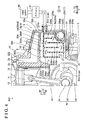
- a separator portion 6 separatator structure formed by a separate member (an individual member) from the cylinder block 2 and the auxiliary machinery bracket 5 is fitted in the void portion 4.
- the separator portion 6 includes a function to perform gas-liquid separation on blow-by gas.
- the void portion 4 serves as an example of a void.
- the separator portion 6 made of resin for example, includes an inlet portion 6a formed at a lower portion (i.e., at the side Z2), an outlet portion 6b formed at an upper portion (i.e., at the side Z1), and a body portion 6c formed between the inlet portion 6a and the outlet portion 6b to include a hollow configuration.
- the body portion 6c includes an inner wall surface 6d with a complex configuration by including protrusions and recesses. In view of manufacturing process, the body portion 6c is obtained from two divided parts in the up-down direction or right-left direction which are integrated by vibration welding, for example, to achieve the separator portion 6 as a single member.
- a first penetration portion 4a and a second penetration portion 4b are formed in the void portion 4.
- the first penetration portion 4a penetrates in an L-shape through a side wall portion 3c formed at an upper portion of the crankcase 3 and a lower portion of the side wall 2c of the cylinder block 2.
- the second penetration portion 4b penetrates through the cylinder block attachment portion 5a of the auxiliary machinery bracket 5 from a side where the recess portion 5d is provided towards the outside of the auxiliary machinery bracket 5 along a direction Y2.
- the separator portion 6 is accommodated in the void portion 4 in a state where the inlet portion 6a is inserted to a portion of the first penetration portion 4a extending in the direction Z while the outlet portion 6b is inserted to the second penetration portion 4b extending in the direction Y.
- the inlet portion 6a serves as an example of an inlet port.
- a clearance S formed by an air layer is defined between an outer surface 6f of the body portion 6c and an inner wall surface 4d of the void portion 4.
- the clearance S is formed at least in a way that the outer surface 6f of the body portion 6c is apart from an inner wall surface of the recess portion 5d of the auxiliary machinery bracket 5 (i.e., the inner wall surface 4d of the void portion 4) to an inner side of the void portion 4.
- the clearance S extends, at an upper side of the body portion 6c, from a portion of the cylinder block 2 facing the recess portion 5d towards the recess portion 2d.
- the outer surface 6f of the body portion 6c facing a downward-facing inner wall surface of the recess portion 2d of the cylinder block 2 (i.e., the inner wall surface 4d of the void portion 4) is apart from the recess portion 2d by the clearance S to the inner side of the void portion 4 (i.e., in a downward direction).
- the clearance S also extends, at a lower side of the body portion 6c, from the recess portion 5d of the auxiliary machinery bracket 5 towards the recess portion 2d of the cylinder block 2.
- the outer surface 6f of the body portion 6c facing an upward-facing inner wall surface of the recess portion 2d of the cylinder block 2 i.e., the inner wall surface 4d of the void portion 4
- the clearance S is apart from the recess portion 2d by the clearance S to the inner side of the void portion 4 (i.e., in an upward direction).
- the body portion 6c is configured so that the outer surface 6f is arranged apart from the inner wall surface 4d forming an end portion of the void portion 4 at the side X2 by the clearance S to the inner side and apart from the inner wall surface 4d forming an end portion of the void portion 4 at the side X1 by the clearance S to the inner side.
- the separator portion 6 including a steric configuration is formed so that the outer surface 6f is surrounded and covered by the clearance S formed by the air layer, except for the first and second penetration portions 4a, 4b and a portion in contact with a first passage portion 8a of a coolant flow passage 8 which will be explained later. Because a temperature of the auxiliary machinery bracket 5 or the cylinder block 2, for example, is inhibited from being directly transmitted to the body portion 6c of the separator portion 6, heat retaining properties of the separator portion 6 are secured.
- a seal member 7 is provided for sealing the clearance S between a portion in the vicinity of the inlet portion 6a of the separator portion 6 and the cylinder block 2.
- the seal member 7 is made of a material including elasticity or resiliency and also including both water resistance and oil resistance, i.e., made of a rubber (resin) material, for example. Therefore, atmosphere including water and oil, specifically, blow-by gas and oil mist, at the crankcase 3 is inhibited from entering the clearance S between the void portion 4 and the outer surface 6f of the body portion 6c from the first penetration portion 4a.
- a seal member is not provided between a portion in the vicinity of the outlet portion 6b of the separator portion 6 and the second penetration portion 4b of the auxiliary machinery bracket 5.
- the outlet portion 6b of the separator portion 6 and a conduit (a hose member) connecting the outlet portion 6b and a positive crankcase ventilation (PCV) valve 81 are connected to each other via a seal member 9 so that blow-by gas flowing through the outlet portion 6b is inhibited from being leaked to the outside.
- the engine 100 is configured in a way that blow-by gas (i.e., unburnt air-fuel mixture) being leaked to the crankcase 3 (specifically, the crank chamber 3a) provided at a lower side of the cylinder 2a from a clearance between an inner wall surface of the cylinder (cylinder liner) 2a and a piston ring 13 is again introduced to an intake system 80 that sends air to the cylinder 2a.
- a flow passage for blow-by gas (blow-by gas flow passage) is formed to connect the crankcase 3 and the PCV valve 81 that is connected to the intake system 80.
- the separator portion 6 constitutes a portion of the blow-by gas flow passage.
- the crankcase 3 and the separator portion 6 are connected by the inlet portion 6a while the PCV valve 81 and the separator portion 6 are connected by the outlet portion 6b.
- the inner wall surface 6d of the body portion 6c includes plural projecting wall portions (in the embodiment, four projecting wall portions) 6e each of which includes a plate form.
- the projecting wall portions 6e extend on a horizontal surface (i.e., a plane X-Y). Specifically, the projecting wall portions 6e project from the inner wall surface 6d at the side Y1 and from the inner wall surface 6d at the side Y2 alternately along a horizontal direction (i.e., in directions Y1 and Y2). Tip end portions of the projecting wall portions 6e overlap each other at a substantially center portion of the body portion 6c in the direction Y in a state to be apart from one another by predetermined intervals in the direction Z.
- the separator portion 6 forms a labyrinth structure at an inner portion. Blow-by gas leaked to the crankcase 3 (the crank chamber 3a) flows through the separator portion 6 that includes the labyrinth structure (labyrinth system) from the lower portion corresponding to the inlet portion 6a to the upper portion corresponding to the outlet portion 6b to be introduced to the PCV valve 81 and thereafter to be led to the intake system 80.
- the labyrinth structure labyrinth system
- Blow-by gas containing hydrocarbon is mixed with oil mist that is generated at the crank chamber 3a.
- oil mist in fine particle form is effectively collected from blow-by gas that stays at an inner void of the separator portion 6 of which a flow passage length from the inlet portion 6a to the outlet portion 6b is elongated in a reciprocating meander form by the inner wall surface 6d including the plural projecting wall portions 6e.
- Blow-by gas that is leaked to the crankcase 3 flows into the separator portion 6 via the inlet portion 6a at the lower portion as illustrated by an arrow P to be repeatedly collided against the inner wall surface 6d (the projecting wall portions 6e) while remaining and staying in the body portion 6c. Then, the aforementioned blow-by gas is discharged towards the PCV valve 81 from the outlet portion 6b. The blow-by gas in which oil is separated by the gas-liquid separation is guided by the PCV valve 81 to flow back to the intake system 80.
- the coolant flow passage 8 including a predetermined layout is configured to be formed at the engine body 10.
- the coolant flow passage 8 includes the first passage portion 8a extending in the direction X2 within the auxiliary machinery bracket 5, a second passage portion 8b extending obliquely upwardly (i.e., substantially in the arrow Z1 direction) within the auxiliary machinery bracket 5, a third passage portion 8c connected to the second passage portion 8b to extend in the direction X1 within the auxiliary machinery bracket 5, and a fourth passage portion 8d connected to the third passage portion 8c to extend in the direction Y within the auxiliary machinery bracket 5 and the cylinder block 2.
- the first passage portion 8a, the water pump 70, the second passage portion 8b, the third passage portion 8c and the fourth passage portion 8d are connected in the mentioned order in the coolant flow passage 8 along a flow direction of coolant (i.e., cooling fluid or antifreeze fluid, for example).
- coolant i.e., cooling fluid or antifreeze fluid, for example.
- the fourth passage portion 8d is connected to the vicinity of a lower end portion of the water jacket 2b at the inner portion of the cylinder block 2.
- the fourth passage portion 8d also serves as a portion of the water jacket 2b.
- the first passage portion 8a serves as an example of a coolant flow passage.
- the coolant flow passage is not only a passage through which coolant formed by normal water flows but also a passage through which coolant formed by antifreeze fluid (cooling fluid) including antifreezing agent or rust-preventive agent and corrosion prevention agent, for example, for inhibiting corrosion of a metal component.
- coolant cooling fluid
- coolant (cooling fluid) cooled by a radiator flows in the arrow X2 direction through the first passage portion 8a provided within the auxiliary machinery bracket 5 and connected to a conduit (a hose member) that extends from the radiator so that the coolant is suctioned into the water pump 70.
- the coolant discharged from the water pump 70 flows through the second passage portion 8b within the auxiliary machinery bracket 5 in the obliquely upward direction (i.e., substantially in the arrow Z1 direction) and thereafter flows through the third passage portion 8c in the arrow X1 direction.
- the coolant flows through the fourth passage portion 8d in the arrow Y1 direction to flow into the water jacket 2b.
- the coolant that receives heat from the cylinder head 1 and the cylinder block 2 is discharged from the cylinder head 1 and is returned to the radiator for cooling.
- the coolant flow passage 8 formed by the first to fourth passage portions 8a, 8b, 8c, and 8d serves as a portion of flow passage for cooling the cylinder head 1 and the cylinder block 2 in a case where the engine 100 is steadily driven.
- the coolant flow passage 8 within the auxiliary machinery bracket 5 also functions to warm up or heat the inside of the separator portion 6 that is internally disposed at the engine body 10 by using heat of coolant warmed or heated by the engine 100 immediately after the start of the engine 100.
- a flow passage switching valve is driven so that coolant discharged from the cylinder head 1 and the cylinder block 2 flows back to the first passage portion 8a within the auxiliary machinery bracket 5 without passing through the radiator, i.e., without being cooled. Accordingly, immediately after the start of the engine 100, the inside of the separator portion 6 is heated by the effective usage of heat of coolant that is heated by the engine 100.
- blow-by gas generated immediately after the start of the engine 100 to pass through the separator portion 6 is heated.
- Water vapor component contained in blow-by gas is restrained from being condensed at a cooled portion of the inner wall surface 6d of the body portion 6c.
- the first passage portion 8a for heating the separator portion 6 is arranged along the outer surface 6f of the body portion 6c so as to be positioned closer to the outer side of the separator portion 6.
- a conduit wall portion of the first passage portion 8a at the auxiliary machinery bracket 5 and a portion of the outer surface 6f of the body portion 6c are in contact with each other.
- the first passage portion 8a is arranged closer to the lower portion (i.e., the side Z2) of the body portion 6c where the inlet portion 6a is provided. That is, the first passage portion 8a, through which coolant at a relatively high temperature flows immediately after heated by the engine 100, is arranged at the lower portion of the separator portion 6.
- water vapor contained in blow-by gas immediately after flowing from the inlet portion 6a may be inhibited from being condensed.
- crankshaft timing sprocket attached to the crankshaft 40 and a camshaft timing sprocket for driving a camshaft assembled within the cylinder head 1 are connected to each other by a timing chain.
- a crank pulley is attached to a front end portion 40a of the crankshaft 40 to be rotatable.
- the auxiliary machines such as the water pump 70 and a compressor for air conditioning are driven by a belt attached to the crank pulley.
- a rear end portion 40b of the crankshaft 40 is connected to a power transmission portion formed by a transmission, or the like.
- the separator portion 6 is arranged at the void portion 4 between the cylinder block 2 and the auxiliary machinery bracket 5 in a state to serve as the separate member (individual member) from the cylinder block 2 and the auxiliary machinery bracket 5.
- the separator portion 6 serving as the separate member (separate component) from the cylinder block 2 and the auxiliary machinery bracket 5 may be thermally isolated from the side wall 2c of the cylinder block 2 and the auxiliary machinery bracket 5 which are directly exposed to an outside air, by the clearance S functioning as a heat insulating layer between the separator portion 6 and each of the auxiliary machinery bracket 5 and the cylinder block 2.
- the separator portion 6 is thermally insulated from the cylinder block 2 and the auxiliary machinery bracket 5 by means of the clearance S as the heat insulating layer, the separator portion 6 is unlikely to be directly affected by the outside air temperature.
- the temperature of the separator portion 6 is restrained from decreasing.
- the heat retaining properties of the separator portion 6 are thus secured to effectively inhibit condensation of water vapor in blow-by gas flowing through the separator portion 6. As a result, dew condensation water may be inhibited from being mixed into oil that is recovered by the separator portion 6.
- the separator portion 6 is provided as the separate member from the cylinder block 2 and the auxiliary machinery bracket 5, the separator portion 6 including the labyrinth structure may be easily incorporated in the engine body 10 without consideration of which oil separation system is used for conducting the gas-liquid separation on blow-by gas.
- oil collection ability required for the separator portion 6 is different.
- the separator portion 6 includes a system other than the labyrinth system, i.e., includes any oil separation system such as an inertial collision system, a cyclone system, and a filter system, for example, which will be explained later, inhibition of dew condensation of water vapor in blow-by gas is effectively achieved by heat-retention of the separator portion, thereby avoiding dew condensation water from being mixed into oil separated and obtained by the gas-liquid separation.
- a system other than the labyrinth system i.e., includes any oil separation system such as an inertial collision system, a cyclone system, and a filter system, for example, which will be explained later.
- the separator portion 6 is disposed in the void portion 4 formed between the cylinder block 2 and the auxiliary machinery bracket 5 while the clearance S is provided relative to at least the auxiliary machinery bracket 5. That is, the separator portion 6 is arranged in the void portion 4 in a state to have the clearance S relative to the auxiliary machinery bracket 5 that does not include a heat source or the like and that may easily directly receive an influence of outside air temperature. Thus, even in a state where the auxiliary machinery bracket 5 is cooled by the outside air, the clearance S functions as the heat insulating layer to inhibit the temperature of the auxiliary machinery bracket 5 from being directly thermally transmitted to the separator portion 6 in the void portion 4. Because the heat retaining properties of the separator portion 6 relative to the outside air temperature are effectively maintained, dew condensation of water vapor in blow-by gas that flows through the separator portion 6 resulting from the outside air temperature may be securely inhibited.
- the separator portion 6 is disposed in the void portion 4 between the cylinder block 2 and the auxiliary machinery bracket 5 in a state where the clearance S is formed relative to both the auxiliary machinery bracket 5 and the cylinder block 2. That is, the separator portion 6 is arranged in a state to have the clearance S not only relative to the auxiliary machinery bracket 5 that is easily influenced by the outside air temperature but also relative to the cylinder block 2.
- a heat insulation effect (heat insulation ability) is obtained by the clearance S defined between the separator portion 6 and each of the auxiliary machinery bracket 5 and the cylinder block 2 to thereby secure heat-retention of the separation portion 6 in the void portion 4.
- dew condensation of water vapor in blow-by gas flowing through the separator portion 6 immediately after cold start of the engine 100 may be securely inhibited.
- the clearance S between the separator portion 6 and at least the auxiliary machinery bracket 5 serves as the heat insulating layer formed by the air layer.
- the heat insulation effect heat insulation ability
- the heat insulation ability may be easily exerted at the clearance S between the separator portion 6 and at least the auxiliary machinery bracket 5 without a usage of special material for exerting the heat insulation effect (heat insulation ability).
- the separator portion 6 includes the labyrinth system so that the labyrinth structure is formed at the inner portion by the plural projecting wall portions 6e protruding from the inner wall surface 6d. Because of the labyrinth structure at the inner void of the separator portion 6, oil mist in fine particle form contained in blow-by gas may be effectively collected and captured by retention of blow-by gas at the inner void of the separator portion 6 where the flow passage length from the inlet portion 6a to the outlet portion 6b formed by the inner wall surface 6d (including the plural projecting wall portions 6e) is elongated in a reciprocating meander form.
- Oil mist may be also effectively collected and captured, in the process of flowing of blow-by gas, by repeated collisions of oil mist against the inner wall surface 6d (including the plural projecting wall portions 6e) in a complex form.
- blow-by gas is inhibited from being cooled by the inner wall surface 6d (including the plural projecting wall portions 6e) so as to effectively inhibit dew condensation of water vapor in blow-by gas flowing through the separator portion 6.
- the separator portion 6 includes the inlet portion 6a that introduces blow-by gas from the cylinder block 2 and the seal member 7 that seals the clearance S between the portion in the vicinity of the inlet portion 6a of the separator portion 6 and the cylinder block 2. Accordingly, a portion of blow-by gas introduced to the separator portion 6 is inhibited from being leaked to (i.e., inhibited from entering) the clearance S (the air layer in the void portion 4) that outwardly surrounds the outer surface 6f of the separator portion 6 and that is formed between the outer surface 6f of the separator portion 6 and each of the cylinder block 2 and the auxiliary machinery bracket 5. As a result, oil in blow-by gas is inhibited from unnecessary entering to be retained in the clearance S.
- the auxiliary machinery bracket 5 includes the coolant flow passage 8, and the separator portion 6 is disposed in the vicinity of the coolant flow passage 8 of the auxiliary machinery bracket 5. Accordingly, after the start of the engine 100, heat of coolant (high-temperature water) sufficiently heated by the engine 100 is transmitted to the inner void of the separator portion 6 to warm or heat the separation portion 6. After once the separator portion 6 is heated by heat of coolant, the heat retaining properties of the separator portion 6 disposed in the void portion 4 between the cylinder block 2 and the auxiliary machinery bracket 5 are secured. Thus, blow-by gas flowing through the separator portion 6 may be maintained at a predetermined temperature even in a case where the auxiliary machinery bracket 5 is exposed to a low-temperature outside air.
- coolant high-temperature water
- the separator portion 6 is made of resin.
- the heat insulation effect (heat insulation ability) possessed by the separator portion 6 itself is used so that the separator portion 6 may be further unlikely to be influenced by the outside air temperature.
- two divided parts because of manufacturing process are united each other by vibration welding, for example, to thereby easily manufacture the separator portion 6 as a single member.
- an inner structure i.e., the inner wall surface 6d including the plural projecting wall portions 6e
- a desired form i.e., labyrinth structure
- FIG. 4 A second embodiment will be explained with reference to Figs. 2 and 4 .
- an outer surface 206f of a separator portion 206 is disposed to an inner portion of a cylinder block 202 (i.e., the crank chamber 3a).
- configurations of the second embodiment substantially similar to the first embodiment bear the same reference numerals as the first embodiment.
- the auxiliary machinery bracket 5 is assembled on a side wall 202c of the cylinder block 202 via the seal member 14.
- An opening portion 202e penetrating through the side wall 202c to the crank chamber 3a is formed at an inner wall portion 202d of the side wall 202c to which the auxiliary machinery bracket 5 is attached.
- the inner wall portion 202d constitutes a surface at an outer side of the cylinder block 202.
- the portion 202d is defined as the inner wall portion.
- the opening portion 202e of the inner wall portion 202d includes a relatively large opening area.
- the auxiliary machinery bracket 5 is assembled on the cylinder block 202 in a state where the recess portion 5d of the cylinder block attachment portion 5a faces the opening portion 202e (the inner wall portion 202d) of the side wall 202c so that outer edge portions of the cylinder block attachment portion 5a and the side wall 202c are in contact with each other.
- the engine 200 serves as an example of the internal combustion engine.
- the void portion 204 in a predetermined form is defined between the inner wall portion 202d (the opening portion 202e) of the side wall 202c and the recess portion 5d of the cylinder block attachment portion 5a in a state where the auxiliary machinery bracket 5 is assembled on the cylinder block 202.
- the void portion 204 is in communication with the crank chamber 3a provided at the inner portion of the cylinder block 202.
- the separator portion 206 made of resin and serving as a separate member (individual member) from the cylinder block 202 and the auxiliary machinery bracket 5 is arranged in the void portion 204.
- the void portion 204 serves as an example of the void.
- the separator portion 206 includes an inlet portion 206a formed at a lower portion, an outlet portion 206b formed at an upper portion, and a body portion 206c.
- the body portion 206c includes an inner wall surface 206d at an inner portion, the inner wall surface 206d including the labyrinth structure.
- the inlet portion 206a is disposed to face the crank chamber 3a via the opening portion 202e, and the outlet portion 206b is fitted in the void portion 204 in a state to be inserted to a penetration bore 204b.
- the outlet portion 206b of the separator portion 206 is fitted in the penetration bore 204b of the auxiliary machinery bracket 5 via a seal member 209.
- the seal member 209 is made of a material including elasticity or resiliency and also including oil resistance, i.e., made of a rubber (resin) material, for example. Therefore, because of the seal member 209, atmosphere including blow-by gas and oil mist, i.e., water and oil, at the crankcase 3 is inhibited from being leaked to the outside of the auxiliary machinery bracket 5 from the penetration bore 204b.
- a clearance T formed by the air layer is also defined between the outer surface 206f of the body portion 206c and the inner wall surface 204d of the void portion 204 in a state where the separator portion 206 is disposed in the void portion 204.
- the clearance T is formed so that the outer surface 206f of the body portion 206c is apart from the inner wall surface of the recess portion 5d of the auxiliary machinery bracket 5 to an inner side of the void portion 204.
- the clearance T extends towards the opening portion 202e along the inner wall portion 202d of the cylinder block 202 from the recess portion 5d of the auxiliary machinery bracket 5 by following the outer surface 206f in the up-down direction (in the direction Z) and the front-rear direction (in the direction Z).
- the separator portion 206 including a steric structure is thus configured so that the outer surface 206f is surrounded and covered by the clearance T formed by the air layer, except for the penetration bore 204b and a portion in connection with the first passage portion 8a (the coolant flow passage 8).
- the heat insulating layer formed by the air layer constituting the clearance T is in communication with the crank chamber 3a via the opening portion 202e of the cylinder block 202. Accordingly, after the start of the engine 200, blow-by gas at a high temperature that is leaked from the lower portion of the cylinder 2a towards the crank chamber 3a not only fills the crank chamber 3a but also fills the clearance T via the opening portion 202e.
- the separator portion 206 is surrounded by blow-by gas at a high temperature filled in the clearance T.
- blow-by gas flowing into the separator portion 206 from the inlet portion 206a as illustrated by the arrow P is repeatedly collided against the inner wall surface 206d (projecting wall portions 206e) while being retained within the body portion 206c. Thereafter, the blow-by gas is discharged from the outlet portion 206b towards the PCV valve 81.
- the inner wall surface 206d of the body portion 206c includes the plural projecting wall portions (in the embodiment, four projecting wall portions) 206e each of which includes a plate form.
- each of the projecting wall portions 206e extends on a vertical surface (i.e., the plane X-Z).
- the projecting wall portions 206e project from the inner wall surface 206d at the side Z1 (upper surface) and from the inner wall surface 206d at the side Z2 (lower surface) alternately along the up-down direction (i.e., in the directions Z1 and Z2).
- Tip end portions of the projecting wall portions 206e overlap each other at a substantially center portion of the body portion 206c in the direction Z in a state to be apart from one another by predetermined intervals in the direction Y. Accordingly, the separator portion 206 forms the labyrinth structure at the inner portion.
- the first passage portion 8a for warming or heating the separator portion 206 is arranged along the outer surface 206f of the body portion 206c to be positioned closer to the outer side of the separator portion 206.
- a conduit wall portion of the first passage portion 8a at the auxiliary machinery bracket 5 and a portion of the outer surface 206f of the body portion 206c are in contact with each other.
- the first passage portion 8a is arranged closer to the lower portion (i.e., the side Z2) of the body portion 206c where the inlet portion 206a is provided.
- the other configurations of the engine 200 in the second embodiment are substantially the same as the first embodiment.
- the separator portion 206 is disposed in a state where the clearance T serving and constituting the heat insulating layer that includes the air layer is formed relative to both the auxiliary machinery bracket 5 and the cylinder block 202. Then, the opening portion 202e is formed at the inner wall portion 202d of the cylinder block 202 so that the heat insulating layer including the air layer is in communication with the crank chamber 3a serving as the inner portion of the cylinder block 202. Accordingly, the separator portion 206 arranged in the void portion 204 between the auxiliary machinery bracket 5 and the cylinder block 202 is surrounded by the heat insulating layer (air layer) in communication with (the inside of) the crank chamber 3a serving as the inner portion of the cylinder block 202.
- gas within the crank chamber 3a is warmed or heated by blow-by gas or engine oil that is stored at the oil storage portion 3b, for example, which results in generation of gas at a high temperature such as blow-by gas, for example.
- the separator portion 206 is surrounded by such gas at a high temperature.
- the heat retaining properties of the separator portion 206 may be easily secured after the start of the engine 200.
- a third embodiment will be explained with reference to Figs. 2 and 5 .
- a separator portion 306 including a cyclone system as the oil separation system is applied.
- configurations of the third embodiment substantially similar to the first embodiment bear the same reference numerals as the first embodiment.
- the auxiliary machinery bracket 5 is assembled on a side wall 302c of a cylinder block 302.
- a void portion 304 in a predetermined form is defined between a recess portion 302d of the side wall 302c and the recess portion 5d of the cylinder block attachment portion 5a.
- the separator portion 306 serving as a separate member (individual member) from the cylinder block 302 and the auxiliary machinery bracket 5 is arranged in the void portion 304 formed between the cylinder block 302 and the auxiliary machinery bracket 5.
- the void portion 304 serves as an example of the void.
- the engine 300 serves as an example of the internal combustion engine.
- the cyclone-type separator portion 306 is applied.
- the separator portion 306 includes an inlet portion 306a formed at the side wall 302c, an outlet portion 306b formed at an upper portion (i.e., at the side Z1), a body portion 306c constituting a cyclone chamber formed between the inlet portion 306a and the outlet portion 306b, and an oil passage portion 306d to which oil that is separated from blow-by gas is dropped.
- blow-by gas rotates or swirls at an inner portion of the body portion 306c constituting the cyclone chamber in a cylindrical form so as to separate oil mist contained in blow-by gas by centrifugal separation.
- a method for collecting oil mist is different from the labyrinth system or the inertial collision system, for example.
- a configuration of the separator portion 306 of the cyclone system is greatly different from a configuration of the separator portion 6 of the labyrinth system (inertial collision system).
- the inlet portion 306a serves as an example of the inlet port.
- the void portion 304 includes a first penetration portion 304a penetrating through the recess portion 302d in the horizontal direction, a second penetration portion 304b penetrating through the cylinder block attachment portion 5a of the auxiliary machinery bracket 5 from a side where the recess portion 5d is provided towards the outside of the auxiliary machinery bracket 5 along the direction Y2, and a third penetration portion 304c penetrating through the recess portion 302d at a lower side (i.e., at the side Z2) of the first penetration portion 304a in a state where the auxiliary machinery bracket 5 is assembled on the cylinder block 302.
- the separator portion 306 is accommodated within the void portion 304 in a state where the inlet portion 306a is inserted to the first penetration portion 304a, the outlet portion 306b is inserted to the second penetration portion 304b, and the oil passage portion 306d is inserted to the third penetration portion 304c.
- the separator portion 306 including a steric structure is configured so that an outer surface 306f is surrounded and covered by a clearance U formed by the air layer, except for the first, second, and third penetration portions 304a, 304b, 304c, and a portion in contact with the first passage portion 8a (the coolant flow passage 8).
- the temperature of the auxiliary machinery bracket 5 or the cylinder block 302 is restrained from being directly transmitted to the body portion 306c of the separator portion 306.
- the first passage portion 8a (the coolant flow passage 8) is disposed so as not to protrude into the separator portion 306.
- the separator structure may be provided at the inner void portion 304 of the separator portion 306 of which internal volume is secured without the influence of the arrangement of the first passage portion 8a (the coolant flow passage 8).
- the inlet portion 306a and the oil passage portion 306d are attached to the first penetration portion 304a and the third penetration portion 304c via seal members 351 and 352 respectively.
- the seal member 351 seals the clearance U between a portion in the vicinity of the inlet portion 306a of the separator portion 306 and the cylinder block 302 (the recess portion 302d) while the seal member 352 seals the clearance U between a portion in the vicinity of the oil passage portion 306d and the cylinder block 302 (the recess portion 302d).
- the other configurations of the engine 300 in the third embodiment are substantially the same as the first embodiment.
- the separator portion 306 including the cyclone system (centrifugal separation system) and serving as the separate member (individual member) from the cylinder block 302 and the auxiliary machinery bracket 5 is provided. Therefore, without consideration of which oil separation system is used for conducting the gas-liquid separation on blow-by gas, the separator portion 306 including the cyclone system (centrifugal separation system) and oil collection ability depending on design specifications of the engine 300 may be easily incorporated in the engine body 10.
- the separator portion 306 includes the inlet portion 306a introducing blow-by gas from the cylinder block 302 and the oil passage portion 306d through which oil that is separated from blow-by gas at the body portion 306c flows. Then, the seal member 351 is provided to seal the clearance U between the portion in the vicinity of the inlet portion 306a and the cylinder block 302. The seal member 352 is also provided to seal the clearance U between the portion in the vicinity of the oil passage portion 306d and the cylinder block 302.
- a fourth embodiment will be explained with reference to Figs. 1 , 2 , and 6 .
- a separator portion 406 including a filter system as the oil separation system is applied.
- configurations of the fourth embodiment substantially similar to the first embodiment bear the same reference numerals as the first embodiment.
- the auxiliary machinery bracket 5 is assembled on the side wall 2c of the cylinder block 2.
- the void portion 4 in the predetermined form is defined between the recess portion 2d of the side wall 2c and the recess portion 5d of the cylinder block attachment portion 5a.
- the separator portion 406 serving as a separate member (individual member) from the cylinder block 2 and the auxiliary machinery bracket 5 is arranged in the void portion 4 formed between the cylinder block 2 and the auxiliary machinery bracket 5.
- the engine 400 serves as an example of the internal combustion engine.
- the filter-type separator portion 406 is applied.
- the separator portion 406 includes an inlet portion 406a formed at a lower portion (i.e., at the side Z2), an outlet portion 406b formed at an upper portion (i.e., at the side Z1), and a body portion 406c formed between the inlet portion 406a and the outlet portion 406b.
- a filter member 401 is disposed in an inner void of the body portion 406c.
- the body portion 406c includes a fixation portion 406e circumferentially formed at an inner wall surface 406d to extend along the horizontal direction (i.e., the plane X-Y). An outer edge portion of the filter member 401 is fitted to the fixation portion 406e.
- the inlet portion 406a serves as an example of the inlet port.
- blow-by gas flowing from the inlet portion 406a is collided against the filter member 401 in the upward direction (i.e., in the direction Z1) in the body portion 406c.
- oil mist in fine particle form is adsorbed onto the filter member 401.
- Oil adsorbed onto the filter member 401 falls in liquid drop to return to the crankcase 3 (the oil storage portion 3b as illustrated in Fig. 1 ) via the inlet portion 406a.
- Blow-by gas where oil is separated by the gas-liquid separation by the filter member 401 is led to the PCV valve 81 to flow back to the intake system 80.
- the other configurations of the engine 400 in the fourth embodiment are substantially the same as the first embodiment.
- the separator portion 406 including the filter system and serving as the separate member from the cylinder block 2 and the auxiliary machinery bracket 5 is provided. Therefore, without consideration of which oil separation system is used for conducting the gas-liquid separation on blow-by gas, the separator portion 406 including the filter system and oil collection ability depending on design specifications of the engine 400 may be easily incorporated in the engine body 10.
- the other effects of the fourth embodiment than the aforementioned effects are substantially the same as the first embodiment.
- a fifth embodiment will be explained with reference to Figs. 1 , 5 , 7 to 9 .
- a separator portion 506 which is similar to the separator portion 6 in the first embodiment but of which separator function further improves than the separator portion 6 by modifying the internal configuration thereof is applied.
- configurations of the fifth embodiment substantially similar to the first and third embodiments bear the same reference numerals as the first and third embodiments.
- the separator portion 506 including the similar labyrinth structure to the separator portion 6 (see Fig. 2 ) in the first embodiment is disposed in the void portion 304 as illustrated in Fig. 7 .
- the engine 500 serves as an example of the internal combustion engine.
- the separator portion 506 includes an inlet portion 506a provided in the vicinity of a center portion in the up-down direction (i.e., in the direction Z), an outlet portion 506b provided at an upper portion (i.e., at the side Z1), and a body portion 506c including a predetermined internal configuration.
- the inlet portion 506a linearly extends (i.e., in a straight tube form) from the outside of the body portion 506c to the inside thereof so as to introduce blow-by gas from the crankcase 3 (the crank chamber 3a).
- the body portion 506c which is formed immediately behind the inlet portion 506a (i.e., at the side Y2 relative to the inlet portion 506a) includes a wall portion 506d against which blow-by gas introduced via the inlet portion 506a is configured to be collided and a storage void 501 formed immediately behind the wall portion 506d and storing blow-by gas after its collision against the wall portion 506d.
- the body portion 506c further includes plural projecting wall portions 506e which form the labyrinth structure and through which blow-by gas in the storage void 501 flows so as to configure the entire inner wall portion of the body portion 506c.
- the wall portion 506d facing the inlet portion 506a protrudes towards the inlet portion 506a further than an inner wall portion 506f formed at the side Y2 in the storage void 501 to extend in the up-down direction.
- the inlet portion 506a serves as an example of the inlet port.
- the inlet portion 506a includes a circular cross-section with an inner diameter D as illustrated in Fig. 8 .
- the wall portion 506d which is not only provided at the position immediately behind the inlet portion 506a but also provided to extend in a band form to the inner wall portions 506f at opposed sides in the body portion 506c in the direction X (i.e., at the side X1 and the side X2) while maintaining the height position (in the direction Z).
- the wall portion 506d is formed to include an uneven surface including projections and recesses as illustrated in Fig. 7 .
- the uneven surface may be in a mild wave form or in a more rugged form than the mild wave form.
- the size or magnitude of projections and recesses in the uneven surface may be uniform over the wall portion 506d or be irregular.
- the surface of the wall portion 506d is inclined in a direction where blow-by gas collided against the wall portion 506d easily flows downward (i.e., in the arrow Z2 direction). Specifically, the surface of the wall portion 506d is inclined in a way that a separation distance (i.e., distance in the direction Y) from the inlet portion 506a (i.e., from a blow-by gas port) increases towards the lower side of the wall portion 506d.
- a horizontal distance L (a minimum value) from an end portion of the inlet portion 506a at the side Y2 to the surface of the wall portion 506d is greater than the inner diameter D of the inlet portion 506a.
- blow-by gas introduced to the body portion 506c via the inlet portion 506a is sharply collided against the wall portion 506d.
- the wall portion 506d includes the uneven surface including projections and recesses, blow-by gas is collided against a larger area of the surface of the wall portion 506d.
- the horizontal distance L is greater than the inner diameter D, some of oil mist (oil drops) in fine particle form contained in blow-by gas and including a relatively greater particle diameter are not only collided against the wall portion 506d but also fall by their own weight within a range of the horizontal distance L.
- oil mist contained in blow-by gas is separated therefrom to some extent. Oil drops separated from blow-by gas fall along the surface of the wall portion 506d that is inclined downward.
- FIG. 7 illustrates the storage void 501 that seems to be divided into two separate portions, i.e., one of the portions is formed at an upper side (i.e., at the side Z1) than the inlet portion 506a and the other of the portions is formed at a lower side (i.e., at the side Z2) than the inlet portion 506a. In practice, however, as illustrated in Fig.
- the storage void 501 serving as a single void is formed to surround a wall portion of the inlet portion 506a.
- Fig. 8 illustrates blow-by gas that diffuses to the portion at the upper side (at the side Z1) than the inlet portion 506a and to the portion at the lower side (at the side Z2) than the inlet portion 506a. Accordingly, oil mist is further separated from blow-by gas in a case where blow-by gas is retained at the upper side of the inlet portion 506a and the lower side of the inlet portion 506a.
- the plural projecting wall portions (in the embodiment, two projecting wall portions) 506e are alternately disposed to form the labyrinth structure at a rear area (i.e., in a void at the side Z1) of a ceiling portion 501 a of the storage void 501 at the upper side than the inlet portion 506a.
- the ceiling portion 501 a of the storage void 501, the two projecting wall portions 506e, and a ceiling portion 506g of the body portion 506c overlap one another while including predetermined intervals in the direction Z in a state to expand along the horizontal direction (i.e., on the plane X-Y).
- the flow passage of blow-by gas spreads to the rear side of the ceiling portion 501 a of the storage void 501 via a slit portion 502 formed at the ceiling portion 501 a of the storage void 501 and to a rear side of one of the projecting wall portions 506e positioned at the lower side (at the side Z2) (which will be hereinafter referred to as the lower projecting wall portion 506e) via a slit portion 503 formed at the lower projecting wall portion 506e.
- the flow passage of blow-by gas spreads to a rear side of the other of the projecting wall portions 506e positioned at the upper side (at the side Z1) (which will be hereinafter referred to as the upper projecting wall portion 506e) via a slit portion 504 formed at the upper projecting wall portion 506e.
- the outlet portion 506b is obtained by a penetration bore formed at a corner area at the rear side (corresponding to the lower side of the ceiling portion 506g) of the upper projecting wall portion 506e.
- Each of the ceiling portion 501a, the projecting wall portions 506e, and the ceiling portion 506g includes a substantially rectangular form in a planar view.
- the slit portion 502 is a continuous bore in an L-shape forming a clearance among side portions of the ceiling portion 501 a at the side Y1 and the side X2 and the inner wall portion 506f of the body portion 506c.
- the slit portion 503 is also a continuous bore in an L-shape forming a clearance among side portions of the lower projecting wall portion 506e at the side Y2 and the side X1 and the inner wall portion 506f of the body portion 506c.
- the slit portion 504 is also a continuous bore in an L-shape forming a clearance among side portions of the upper projecting wall portion 506e at the side Y1 and the side X2 and the inner wall portion 506f of the body portion 506c.
- the slit portions 502, 503 and 504 are alternately disposed at one side and the other side of a diagonal line connecting a corner portion at the side Y1 and the side X2 and a corner portion at the side Y2 and the side X1 within the body portion 506c.
- blow-by gas tentatively retained in the storage void 501 flows in a reciprocating manner and a meander manner in the direction X and the direction Y to pass through the slit portions 502, 503 and 504 in the mentioned order in the upward direction to be led to the outlet portion 506b.
- the separator portion 506 includes an oil discharge port 506h for discharging oil in blow-by gas (i.e., oil separated from blow-by gas) stored in the storage void 501.
- the oil discharge port 506h is disposed in the vicinity of a bottom portion 501 b positioned at the side Z2 of the storage void 501 so as to open in the horizontal direction (in the direction X).
- the oil discharge port 506h in a vertically elongated form, i.e., elongated in the direction Z, is formed at a portion of the inner wall portion 506f at the side X2 extending in the up-down direction (in the direction Z) to open to the storage void 501.
- oil in liquid form separated from blow-by gas at the wall portion 506d and the storage void 501 to fall is appropriately discharged to the crankcase 3 (the oil storage portion 3b) via the oil discharge port 506h in the vertically elongated form.
- oil mainly flows through a lower portion (at the side Z2) of a cross-section area of the oil discharge port 506h in the vertically elongated form.
- a connection passage i.e., a small bore portion 505 through which air mainly flows
- connecting the storage void 501 and the crankcase 3 (the crank chamber 3a) is formed at an upper portion (at the side Z1) of the cross-section area of the oil discharge port 506h (an approximate region is indicated by broken lines in Figs.
- the separator structure may be provided at the inner void portion 304 of the separator portion 506 of which internal volume is secured without the influence of the arrangement of the first passage portion 8a (the coolant flow passage 8).
- the conduit wall portion of the first passage portion 8a at the auxiliary machinery bracket 5 is disposed along an outer surface 506j of the separator portion 506 positioned at the side Z1 of the storage void 501, instead of being disposed at a height position (in the direction Z) facing the wall portion 506d.
- the storage void 501 in which blow-by gas is retained or stored is warmed or heated indirectly by coolant at a relatively high temperature.
- water vapor contained in blow-by gas which is immediately after collided against the wall portion 506d after flowing from the inlet portion 506a is unlikely to be condensed.
- further separation of oil mist from blow-by gas in the storage void 501 may be facilitated.
- the other configurations of the engine 500 in the fifth embodiment are substantially the same as the first embodiment.
- the separator portion 506 is configured to include the inlet portion 506a introducing blow-by gas from the cylinder block 2, the wall portion 506d which is provided immediately behind the inlet portion 506a and against which blow-by gas introduced via the inlet portion 506a is collided, and the storage void 501 which is provided immediately behind the wall portion 506d and which stores or retains blow-by gas after its collision against the wall portion 506d. Accordingly, blow-by gas introduced into the body portion 506c via the inlet portion 506a is sharply collided against the wall portion 506d to effectively separate oil mist (oil drops) in fine particles contained in blow-by gas.
- the blow-by gas after its collision is diffused to the storage void 501 in the up-down direction and the flow speed of blow-by gas is reduced so that the blow-by gas is retained in the storage void 501, which leads to further separation of oil mist.
- the function of the separator portion 506 for separating oil may improve accordingly.
- the oil discharge port 506h in the vertically elongated form in the up-down direction (in the direction Z) is provided at the separator portion 506 for discharging oil in blow-by gas that is retained or stored in the storage void 501.
- oil in liquid form separated from blow-by gas at the wall portion 506d and the storage void 501 drops and falls to be appropriately discharged to the crankcase 3 (the oil storage portion 3b) (i.e., discharged to the outside of the separator portion 506 to the inside of the cylinder block 2) via the oil discharge port 506h in the vertically elongated form.
- oil mainly flows out through the lower portion (at the side Z2) of the cross-section area of the oil discharge port 506h.
- the upper portion (at the side Z1) of the cross-section area of the oil discharge port 506h may form or include the connection passage (i.e., the small bore portion 505 through which air flows) connecting the storage void 501 and the crankcase 3 with each other.
- the connection passage i.e., the small bore portion 505 through which air flows
- oil intended to be discharged to the crankcase 3 (the oil storage portion 3b) and air within the crankcase 3 are immediately replaced with each other via the oil discharge port 506h.
- oil in liquid form including viscosity may be immediately discharged from the oil discharge port 506h.
- the storage void 501 including a predetermined void capacity may be constantly secured because oil in liquid phase is inhibited from remaining in the storage void 501, thereby easily maintaining the function of the separator portion 506.
- the wall portion 506d is configured to include the surface (uneven surface) including projections and recesses.
- blow-by gas may be collided against a larger area of the surface of the wall portion 506d corresponding to the unevenness (the projections and recesses) in the surface to thereby effectively collect and capture oil mist in fine particles contained in blow-by gas by the uneven surface including projections and recesses.
- the wall portion 506d is configured to include the surface inclined in the direction in which blow-by gas that is collided against the wall portion 506d easily flows downward (in the arrow Z2 direction).
- blow-by gas after collided against the wall portion 506d is easily led to the storage void 501 formed at the lower side than the inlet portion 506a.
- blow-by gas may be retained or stored in the storage void 501 for a long period of time.
- oil mist may be sufficiently separated from blow-by gas in the storage void 501.
- the embodiments are not limited to include the aforementioned configurations and may be appropriately changed or modified as follows.
- the separator portion 6, 206, 306, 406, 506 made of resin is disposed in the void portion 4, 204, 304 formed between the cylinder block 2, 202, 302 and the auxiliary machinery bracket 5.
- the separator portion 6, 206, 306, 406, 506 made of metallic may be disposed in the void portion 4, 204, 304 between the cylinder block 2, 202, 302 and the auxiliary machinery bracket 5. Even the metallic separator portion may be unlikely to receive an influence of the outside air temperature while being thermally insulated by means of the void portion 4, 204, 304 (the clearance S, T, U). The heat-retaining properties of the metallic separator portion are maintained to thereby inhibit condensation of water vapor in blow-by gas flowing through the separator portion.
- the separator structure of the internal combustion engine is applied in a state where the auxiliary machinery bracket 5 to which the water pump 70, an alternator, and a compressor serving as the auxiliary machines are configured to be attached and the cylinder block 2, 202 302 are assembled on each other. That is, the auxiliary machinery bracket 5 serves as an exclusive member to which the auxiliary machines are attached.
- the separator structure of the internal combustion engine may be applied to the internal combustion engine in which a timing chain cover or a timing belt cover attached to the engine body 10 serves as the auxiliary machinery attachment member.
- the heat insulating layer formed by the air layer is provided at the clearance S, T, U between the outer surface 6f, 206f, 306f, 406f of the separator portion 6, 206, 306, 406, 506 and the inner wall surface 4d, 204d, 304d of the void portion 4, 204, 304.
- the heat insulating layer made of resin material may be used.
- a foam type heat insulating material such as urethane resin may be filled in the clearance S, T, U.
- the foam type heat insulating material may be filled in a portion of the clearance S, T, U facing the auxiliary machinery bracket 5, or portions of the clearance S facing both the auxiliary machinery bracket 5 and the cylinder block 2, 202 302.
- a fibrous heat insulating material such as glass wool, for example, may be filled in the clearance S, T, U.
- the separator portion 6, 206, 306, 406, 506 may be fitted in the void portion 4.
- the air layer (the heat insulating layer) may be further disposed in a clearance between the separator portion 6, 206, 306, 406, 506 that is surrounded by the cover layer (heat insulating layer) made of the foam type heat insulating material or the fibrous heat insulating material, for example, and the auxiliary machinery bracket 5 (the cylinder block 2, 202 302).
- the labyrinth type separator portion 6, 206, 506 is applied as the separator structure.
- the cyclone type separator portion 306 is applied as the separator structure.
- the filter type separator portion 406 is applied as the separator structure.
- the separator portion including other oil separation type than the aforementioned types may be applied.
- the separator portion may be configured to include divided plural separator chambers where blow-by gas is acquired from one of the separator chambers while blow-by gas is discharged from another one of the plural separator chambers.
- the conduit wall portion of the first passage portion 8a at the auxiliary machinery bracket 5 and the portion of the outer surface 6f, 206f, 406f of the body portion 6c, 206c, 406c, 506c of the separator potion 6, 206, 406, 506 facing the conduit wall portion are in contact with each other.
- a slight gap may be formed between the conduit wall portion of the first passage portion 8a and the outer surface 6f, 206f, 406f of the separator portion 6, 206, 406, 506.
- the temperature of the separator portion 6, 206, 406, 506 is restrained from decreasing.
- the wall portion 506d is configured to include the uneven surface including projections and recesses.
- the wall portion 506d may include a flat surface.
- the single inlet portion 506a is provided at the separator portion 506.
- the separator portion 506 may be configured to include plural inlet portions 506a that are arranged in front of the wall portion 506d against which blow-by gas is collided.
- the inlet portion 506a may be configured to include a polygon cross section instead of a circular cross section.
- the void portion 304 (the clearance U) around the separator portion 506 may be connected to the crank chamber 3a (i.e., corresponding to the configuration of the void portion 204 in the second embodiment).
- the inlet portion 506a that includes the inner diameter D is formed to linearly (in the straight tube form) extend.
- the inner diameter of the inlet portion 506a may vary.
- the engine 100, 200, 300, 400, 500 for automobiles serving as the gasoline engine may be applied.
- the engine 100, 200, 300, 400, 500 formed by a gas engine other than the gasoline engine i.e., the internal combustion engine such as a diesel engine and a gas engine, for example
- the internal combustion engine mounted as a drive source (power source) for equipment other than automobiles may be applied.
- the internal combustion engine and the separator structure thereof that avoid dew condensation water from being mixed into oil recovered from the separator portion 6, 206, 306, 406, 506 may be provided by effectively inhibit condensation of water vapor in blow-by gas flowing through the separator portion 6, 206, 306, 406, 506.
Landscapes
- Engineering & Computer Science (AREA)
- General Engineering & Computer Science (AREA)
- Mechanical Engineering (AREA)
- Chemical & Material Sciences (AREA)
- Combustion & Propulsion (AREA)
- Physics & Mathematics (AREA)
- Acoustics & Sound (AREA)
- Lubrication Details And Ventilation Of Internal Combustion Engines (AREA)
Abstract
Description
- This disclosure generally relates to an internal combustion engine and a separator structure of the internal combustion engine.
- A known internal combustion engine disclosed, for example, in
JP3423649B Reference 1 includes a separator portion for performing gas-liquid separation on blow-by gas. - The internal combustion engine disclosed in
Reference 1 includes a metallic cylinder block, a metallic auxiliary machinery bracket (an auxiliary machinery attachment member) to which auxiliary machines are attached, and a breather chamber (separator portion). In a state where the auxiliary machinery bracket is fixed to a side wall of the cylinder block, a void portion including an inner wall in a predetermined protruding and recessed form is formed between the side wall of the cylinder block in a recess form and a surface of an attachment portion of the auxiliary machinery bracket in a recess form, the side wall of the cylinder block and the surface of the auxiliary machinery bracket facing each other. The void portion is called the breather chamber to function as the separator portion for separating oil for recovery from blow-by gas that is leaked to a crank chamber from a lower portion of a cylinder. In addition, a portion of a coolant flow passage for cooling the internal combustion engine penetrates through the breather chamber across a conduit wall. Accordingly, heat of coolant warmed or heated by the internal combustion engine is transmitted to the breather chamber to thereby warm or heat the breather chamber (void portion). Water vapor in blow-by gas flowing within the breather chamber is thus inhibited from being condensed. - Nevertheless, according to the aforementioned configuration of the breather chamber in the internal combustion engine disclosed in
Reference 1, because the breather chamber (separator portion) is formed by the side wall of the cylinder block in a recess form and the surface of the auxiliary machinery bracket in a recess form facing each other, the inside of the breather chamber is likely to be influenced by an outside air temperature. Specifically, in a case where outside air temperature is low and engine coolant temperature is low at the time of start of the internal combustion engine, for example, the metallic cylinder block and/or the metallic auxiliary machinery bracket are cooled, so that the breather chamber (separator portion) and the inside thereof are inhibited from being easily warmed or heated. Accordingly, immediately after the start of the internal combustion engine, water vapor in blow-by gas flowing within the breather chamber in a cold state appears as dew condensation water that may be easily mixed in oil obtained by the gas-liquid separation within the breather chamber. - A need thus exists for an internal combustion engine and a separator structure of the internal combustion engine which may avoid dew condensation water from being mixed into oil recovered from a separator portion by effectively inhibit condensation of water vapor in blow-by gas flowing through the separator portion.
- According to an aspect of this disclosure, an internal combustion engine includes a cylinder block, an auxiliary machinery attachment member arranged at a side wall of the cylinder block, the auxiliary machinery attachment member to which an auxiliary machine is attached, and a separator portion disposed in a void between the cylinder block and the auxiliary machinery attachment member, the separator portion being provided as a separate member from the cylinder block and the auxiliary machinery attachment member to perform gas-liquid separation on blow-by gas.
- Accordingly, the separator portion serving as the separate member from the cylinder block and the auxiliary machinery attachment member may be thermally isolated from the cylinder block and the auxiliary machinery attachment member which are directly disposed to outside air in a state where a clearance portion between the separator portion and each of the cylinder block and the auxiliary machinery attachment member is utilized as a heat insulating layer. That is, the separator portion is thermally insulated by means of the aforementioned clearance portion (the heat insulating layer) so that the separator portion is unlikely to be directly influenced by an outside air temperature. The temperature of the separator portion is restrained from decreasing in a case where the internal combustion engine is disposed under a low temperature environment after the stop and in a case where a coolant temperature of the internal combustion engine is not sufficiently raised after (immediately after) the start thereof, for example. Accordingly, heat retaining properties of the separator portion are maintained to effectively inhibit condensation of water vapor contained in blow-by gas flowing through the separator portion. Consequently, due condensation water is inhibited from being mixed into oil that is recovered by the separator portion.
- In addition, the separator portion serving as the separate member from the cylinder block and the auxiliary machinery attachment member may be incorporated in the internal combustion engine without consideration of which oil separation system (for example, an inertial collision system, a labyrinth system, a cyclone system, and a filter system) is used for conducting the gas-liquid separation on blow-by gas. Depending on design specifications of the internal combustion engine, oil collection ability required for the separator portion (features of the separator portion in view of design specifications) is different. Nevertheless, even in a case where the separator portion including any oil separation system is applied, inhibition of dew condensation of water vapor in blow-by gas is effectively achieved by heat-retention of the separator portion, thereby avoiding dew condensation water from being mixed into oil separated and obtained by the gas-liquid separation. Thus, high usefulness of the internal combustion engine is obtained.
- The separator portion is disposed in the void between the cylinder block and the auxiliary machinery attachment member in a state where a clearance is formed relative to at least the auxiliary machinery attachment member.
- The separator portion is arranged in the void in a state to have the clearance relative to the auxiliary machinery attachment member that does not include a heat source or the like and that may easily directly receive an influence of the outside air temperature. Thus, even in a state where the auxiliary machinery attachment member is cooled by the outside air, the clearance functions as the heat insulating layer to inhibit the temperature of the auxiliary machinery attachment member from being directly thermally transmitted to the separator portion in the void. Because the heat retaining properties of the separator portion relative to the outside air temperature are effectively maintained, dew condensation of water vapor in blow-by gas that flows through the separator portion resulting from the outside air temperature may be securely inhibited.
- The separator portion is disposed in the void between the cylinder block and the auxiliary machinery attachment member in a state where the clearance is formed relative to both the cylinder block and the auxiliary machinery attachment member.
- The separator portion is arranged in a state to have the clearance not only relative to the auxiliary machinery attachment member that is easily influenced by the outside air temperature but also relative to the cylinder block. Thus, even in a low-temperature state where the temperature of coolant of the internal combustion engine is not heated to a predetermined temperature at the start of the internal combustion engine, for example, heat insulation effect (heat insulation ability) is obtained by the clearance defined between the separator portion and each of the auxiliary machinery attachment member and the cylinder block to thereby secure heat-retention of the separation portion in the void. Specifically, dew condensation of water vapor in blow-by gas flowing through the separator portion immediately after cold start of the internal combustion engine may be securely inhibited.
- A heat insulating layer is formed at the clearance between the separator portion and at least the auxiliary machinery attachment member.
- Thus, even in a state where the auxiliary machinery attachment member is cooled, the heat insulation effect (heat insulation ability) provided at the clearance between the separator portion and the auxiliary machinery attachment member is obtained relative to the auxiliary machinery attachment member to thereby securely maintain heat in the separator portion.
- The heat insulating layer includes an air layer.
- Accordingly, the heat insulation ability may be easily exerted at the clearance between the separator portion and at least the auxiliary machinery attachment member by the usage of the air layer as the heat insulating layer, without a usage of special material for exerting the heat insulation effect (heat insulation ability).
- The separator portion is configured to include a labyrinth structure at an inner portion.
- Because of the labyrinth structure at the inner portion of the separator portion, oil mist in fine particle form contained in blow-by gas may be effectively collected and captured by retention of blow-by gas at an inner void of the separator portion where a flow passage length thereof is elongated.. In a case where the labyrinth type separator portion is applied, blow-by gas is inhibited from being cooled so as to effectively inhibit dew condensation of water vapor in blow-by gas flowing through the separator portion.
- The separator portion includes an inlet port for introducing blow-by gas from the cylinder block, and a seal member is provided to seal a clearance between a portion in a vicinity of the inlet port of the separator portion and the cylinder block.
- Accordingly, a portion of blow-by gas introduced to the separator portion is inhibited from being leaked via the portion in the vicinity of the inlet port to (i.e., inhibited from entering) the void (clearance) that outwardly surrounds the separator portion and that is formed between the separator portion and each of the cylinder block and the auxiliary machinery attachment member. As a result, oil in blow-by gas is inhibited from unnecessary entering to be retained in the void that outwardly surrounds the separator portion (the clearance between an outer surface of the separator portion and each of the cylinder block and the auxiliary machinery attachment member).
- The separator portion is disposed in a state where a clearance that constitutes a heat insulating layer including an air layer is formed between the separator portion and each of the cylinder block and the auxiliary machinery attachment member, and the heat insulating layer including the air layer is connected to an inner portion of the cylinder block.
- Accordingly, the separator portion arranged in the void between the auxiliary machinery attachment member and the cylinder block may be surrounded by the heat insulating layer (air layer) in communication with the inner portion of the cylinder block. In this case, gas at the inner portion of the cylinder block is warmed or heated by blow-by gas or engine oil that is stored at an oil storage portion, for example. Thus, the separator portion is surrounded by such gas at a high temperature. The heat retaining properties of the separator portion may be easily secured after the start of the internal combustion engine.
- The auxiliary machinery attachment member includes a coolant flow passage, and the separator portion is disposed in a vicinity of the coolant flow passage of the auxiliary machinery attachment member.
- Accordingly, after the start of the internal combustion engine, heat of coolant (high-temperature water) sufficiently heated by the internal combustion engine is transmitted to the separator portion (the inner void of the separator portion) to warm or heat the separation portion. After once the separator portion is heated by heat of coolant, the heat retaining properties of the separator portion disposed in the void between the cylinder block and the auxiliary machinery attachment member are maintained. Thus, blow-by gas flowing through the separator portion may be maintained at a predetermined temperature even in a case where the auxiliary machinery attachment member is exposed to a low-temperature outside air.
- The coolant flow passage is disposed in a state to be inhibited from protruding into the separator portion.
- Accordingly, the coolant flow passage is disposed, without protruding into the inner void of the separator portion, in the vicinity of an outer side of the separator portion (the inner void). Without an influence of arrangement of the coolant flow passage, an internal volume is sufficiently secured at the inner void of the separator portion.
- The separator portion includes an inlet port for introducing blow-by gas from the cylinder block, a wall portion which is provided immediately behind the inlet port and against which blow-by gas introduced via the inlet port is collided, and a storage void provided immediately behind the wall portion to store blow-by gas that is collided against the wall portion.
- Accordingly, blow-by gas introduced into the separator portion via the inlet port is sharply collided against the wall portion to effectively separate oil mist (oil drops) in fine particles contained in blow-by gas. The blow-by gas after its collision is diffused to the storage void in the up-down direction and a flow speed of blow-by gas is reduced so that the blow-by gas is retained in the storage void, which leads to further separation of oil mist. The function of the separator portion for separating oil may improve accordingly.
- The separator portion includes an oil discharge port in a vertically elongated form extending in an up-down direction to discharge oil in blow-by gas that is stored in the storage void.
- Thus, oil in liquid form separated from blow-by gas at the wall portion and the storage void drops and falls to be appropriately discharged to the outside of the separator portion (i.e., inside of the cylinder block) via the oil discharge port in the vertically elongated form. In this case, oil mainly flows out through a lower portion of a cross-section area of the oil discharge port. On the other hand, an upper portion of the cross-section area of the oil discharge port may form or include a connection passage (a small bore portion through which air flows) connecting the storage void and the outside of the separator portion (the inside of the cylinder block) with each other. Thus, in the storage void, oil intended to be discharged and air within the cylinder block are immediately replaced with each other via the oil discharge port. As a result, oil in liquid form including viscosity may be immediately discharged from the oil discharge port. The storage void including a predetermined void capacity may be constantly secured because oil in liquid phase is inhibited from remaining in the storage void, thereby easily maintaining the function of the separator portion.
- A separator structure of an internal combustion engine includes a separator portion disposed in a void between a cylinder block and an auxiliary machinery attachment member which is arranged at a side surface of the cylinder block and to which an auxiliary machine is attached, the separator portion being provided as a separate member from the cylinder block and the auxiliary machinery attachment member to perform gas-liquid separation on blow-by gas.
- Accordingly, the separator portion serving as the separate member from the cylinder block and the auxiliary machinery attachment member may be thermally isolated from the cylinder block and the auxiliary machinery attachment member which are directly disposed to outside air in a state where a clearance portion between the separator portion and each of the cylinder block and the auxiliary machinery attachment member is utilized as a heat insulating layer. That is, the separator portion is thermally insulated by means of the aforementioned clearance portion (the insulating layer) so that the separator portion is unlikely to be directly influenced by an outside air temperature. The temperature of the separator portion is restrained from decreasing in a case where the internal combustion engine is disposed under a low temperature environment after the stop and in a case where a coolant temperature of the internal combustion engine is not sufficiently raised after (immediately after) the start thereof, for example. Accordingly, heat retaining properties of the separator portion are maintained to effectively inhibit condensation of water vapor contained in blow-by gas flowing through the separator portion. Consequently, due condensation water is inhibited from being mixed into oil that is recovered by the separator portion.
- In addition, the separator portion serving as the separate member from the cylinder block and the auxiliary machinery attachment member may be applied in the internal combustion engine without consideration of which oil separation system (for example, an inertial collision system, a labyrinth system, and a cyclone system) is used for conducting the gas-liquid separation on blow-by gas. Depending on design specifications of the internal combustion engine, oil collection ability required for the separator portion (features of the separator portion in view of design specifications) is different. Nevertheless, in a case where the separator portion including any oil separation system is incorporated in the internal combustion engine, inhibition of dew condensation of water vapor in blow-by gas is effectively achieved by heat-retention of the separator portion, thereby avoiding dew condensation water from being mixed into oil separated and obtained by the gas-liquid separation. Thus, high usefulness of the internal combustion engine is obtained.
- The foregoing and additional features and characteristics of this disclosure will become more apparent from the following detailed description considered with the reference to the accompanying drawings, wherein:
-
Fig. 1 is a perspective view illustrating an entire configuration of an engine according to a first embodiment disclosed here; -
Fig. 2 is a cross-sectional view illustrating an inner structure of a separator portion in the engine viewed from a front side towards a rear side according to the first embodiment; -
Fig. 3 is a diagram illustrating the inner structure of the separator portion in the engine viewed from a side where an auxiliary machinery bracket is attached to a side wall of a cylinder block according to the first embodiment; -
Fig. 4 is a cross-sectional view illustrating an inner structure of a separator portion in an engine viewed from a front side towards a rear side according to a second embodiment; -
Fig. 5 is a cross-sectional view illustrating an inner structure of a separator portion in an engine viewed from a front side towards a rear side according to a third embodiment; -
Fig. 6 is a cross-sectional view illustrating an inner structure of a separator portion in an engine viewed from a front side towards a rear side according to a fourth embodiment; -
Fig. 7 is a cross-sectional view illustrating an inner structure of a separator portion in the engine viewed from a front side towards a rear side according to a fifth embodiment; -
Fig. 8 is a cross-sectional view illustrating the inner structure of the separator portion taken along line VIII-VIII inFig. 7 according to the fifth embodiment; and -
Fig. 9 is an enlarged view illustrating a configuration around an oil discharge port of the separator portion in the engine according to the fifth embodiment. - Embodiments disclosed here will be explained with reference to the attached drawings.
- First, an
engine 100 according to a first embodiment will be explained with reference toFigs. 1 to 3 . InFig. 1 , main components of theengine 100 are illustrated. InFigs. 2 and3 , detailed structures around acylinder block 2 and anauxiliary machinery bracket 5 are illustrated. In the following explanations, a direction in which acrankshaft 40 extends corresponds to a direction X, a direction orthogonal to the extending direction of thecrankshaft 40 corresponds to a direction Y, and a direction in which acylinder 2a extends corresponds to a direction Z (i.e., in an up-down direction). - As illustrated in
Fig. 1 , theengine 100 for an automobile, for example, includes anengine body 10 made of aluminum alloy, for example, and including acylinder head 1, thecylinder block 2 and acrankcase 3. Theengine 100 formed by a gasoline engine includes achain cover 20 assembled on an end portion of theengine body 10 at a side X2 and ahead cover 30 assembled on an upper side (i.e., at a side Z1) of thecylinder head 1. Theengine 100 serves as an example of an internal combustion engine. - A camshaft and a valve mechanism, for example, are accommodated within the
cylinder head 1. As illustrated inFigs. 1 and2 , thecylinder 2a within which apiston 11 moves in a reciprocation manner in the direction Z and awater jacket 2b are formed at an inner portion of thecylinder block 2 that is connected to a lower portion (i.e., at a side Z2) of thecylinder head 1. Thewater jacket 2b through which coolant (i.e., cooling fluid or antifreeze fluid, for example) flows for cooling thecylinder 2a is formed to surround thecylinder 2a across a partition wall. An intake system is connected to one side (i.e., a side Y2) of thecylinder head 1 for introducing air to each of theplural cylinders 2a formed at thecylinder block 2. - The
cylinder block 2 and thecrankcase 3 that is connected to a lower portion (i.e., at the side Z2) of thecylinder block 2 form a crankchamber 3a at an inner bottom portion of theengine body 10. Thecrankshaft 40 is arranged at thecrank chamber 3a to be rotatably connected about an axis X via thepiston 11 and acon rod 12. InFig. 1 , thecrankshaft 40 is illustrated in a substantially bar form. In fact, however, thecrankshaft 40 is configured to include acrank pin 41 of which a rotation axis is eccentrically specified, abalance weight 42 pinching thecrank pin 41 in an axial direction, and a crank journal 43 in a state where thecrank pin 41 and thebalance weight 42 are connected to the crank journal 43 at a position directly below each of thecylinders 2a. In addition, anoil storage portion 3b is disposed at a lower portion (i.e., at the side Z2) of thecrank chamber 3a for storing engine oil (which will be hereinafter simply referred to as oil). Oil is suctioned by an oil pump from theoil storage portion 3b towards an upper portion of theengine body 10 to lubricate a valve system timing member such as a camshaft, for example, and an outer peripheral surface of thepiston 11 serving as a sliding portion, for example, and thereafter is returned to theoil storage portion 3b by falling by its own weight of oil. - As illustrated in
Fig. 1 , theengine 100 includes theauxiliary machinery bracket 5 made of aluminum alloy, for example. Theauxiliary machinery bracket 5 includes abody portion 50a, a cylinderblock attachment portion 5a and a waterpump attachment portion 5c. The cylinderblock attachment portion 5a includes plural fixation bores (i.e., penetration bores) 5b formed at an outer edge portion of thebody portion 50a. The waterpump attachment portion 5c includesplural fixation holes 5w which serve as screw holes, for example, and via which awater pump 70 for coolant circulation serving as an accessory or an auxiliary machine for theengine 100 is fixed. The cylinderblock attachment portion 5a arranged on a plane X-Z and the waterpump attachment portion 5c arranged on a plane Y-Z are orthogonal to each other. Theauxiliary machinery bracket 5 serves as an example of an auxiliary machinery attachment member. Thewater pump 70 serves as an example of an auxiliary machine. - The
auxiliary machinery bracket 5 is assembled on a predetermined position of aside wall 2c of thecylinder block 2 via aseal member 14 bybolts 91 which are inserted to the respective fixation bores 5b to be fastened to thecylinder block 2 in a state where the cylinderblock attachment portion 5a faces thecylinder block 2. Thewater pump 70 includes anattachment portion 71 at which plural attachment bores (i.e., penetration bores) 72 are formed. Thewater pump 70 is assembled on the waterpump attachment portion 5c via aseal member 15 such as a metal gasket, for example, bybolts 92 which are inserted to the respective attachment bores 72 at theattachment portion 71 to be fastened to thefixation holes 5w formed at the waterpump attachment portion 5c of theauxiliary machinery bracket 5. As illustrated inFig. 3 , thewater pump 70 includes animpeller 74 that is configured to be rotatable within ahousing 73. In a case where apulley 75 provided at the outside of thehousing 73 rotates in a predetermined direction, theimpeller 74 rotates to exert a pumping function. Theauxiliary machinery bracket 5 is also used to secure other auxiliary machines besides thewater pump 70, for example, an alternator (power generating equipment) and a compressor for air conditioning, to a side portion of theengine body 10 at the side Y2 inFig. 2 . - The
side wall 2c of thecylinder block 2 includes arecess portion 2d recessed in a surface at the side Y2. The cylinderblock attachment portion 5a of theauxiliary machinery bracket 5 includes arecess portion 5d recessed in a surface at a side Y1 facing theside wall 2c. Theauxiliary machinery bracket 5 is configured to be assembled on thecylinder block 2 in a state where therecess portion 5d of the cylinderblock attachment portion 5a faces therecess portion 2d of theside wall 2c so that outer edge portions of the cylinderblock attachment portion 5a and theside wall 2c are opposed to each other. Theseal member 14 such as a metal gasket, for example, is disposed at a mating face between thecylinder block 2 and theauxiliary machinery bracket 5. - In the first embodiment, as illustrated in
Fig. 2 , avoid portion 4 in a predetermined form is defined between therecess portion 2d of theside wall 2c and therecess portion 5d of the cylinderblock attachment portion 5a in a state where theauxiliary machinery bracket 5 is assembled on thecylinder block 2. Then, a separator portion 6 (separator structure) formed by a separate member (an individual member) from thecylinder block 2 and theauxiliary machinery bracket 5 is fitted in thevoid portion 4. Theseparator portion 6 includes a function to perform gas-liquid separation on blow-by gas. Thevoid portion 4 serves as an example of a void. - The
separator portion 6 made of resin, for example, includes aninlet portion 6a formed at a lower portion (i.e., at the side Z2), anoutlet portion 6b formed at an upper portion (i.e., at the side Z1), and abody portion 6c formed between theinlet portion 6a and theoutlet portion 6b to include a hollow configuration. Thebody portion 6c includes aninner wall surface 6d with a complex configuration by including protrusions and recesses. In view of manufacturing process, thebody portion 6c is obtained from two divided parts in the up-down direction or right-left direction which are integrated by vibration welding, for example, to achieve theseparator portion 6 as a single member. In a state where theauxiliary machinery bracket 5 is assembled on thecylinder block 2, afirst penetration portion 4a and asecond penetration portion 4b are formed in thevoid portion 4. Thefirst penetration portion 4a penetrates in an L-shape through aside wall portion 3c formed at an upper portion of thecrankcase 3 and a lower portion of theside wall 2c of thecylinder block 2. Thesecond penetration portion 4b penetrates through the cylinderblock attachment portion 5a of theauxiliary machinery bracket 5 from a side where therecess portion 5d is provided towards the outside of theauxiliary machinery bracket 5 along a direction Y2. Theseparator portion 6 is accommodated in thevoid portion 4 in a state where theinlet portion 6a is inserted to a portion of thefirst penetration portion 4a extending in the direction Z while theoutlet portion 6b is inserted to thesecond penetration portion 4b extending in the direction Y. Theinlet portion 6a serves as an example of an inlet port. - In the first embodiment, in a state where the
separator portion 6 is arranged within thevoid portion 4, a clearance S formed by an air layer is defined between anouter surface 6f of thebody portion 6c and aninner wall surface 4d of thevoid portion 4. The clearance S is formed at least in a way that theouter surface 6f of thebody portion 6c is apart from an inner wall surface of therecess portion 5d of the auxiliary machinery bracket 5 (i.e., theinner wall surface 4d of the void portion 4) to an inner side of thevoid portion 4. In addition, the clearance S extends, at an upper side of thebody portion 6c, from a portion of thecylinder block 2 facing therecess portion 5d towards therecess portion 2d. Accordingly, theouter surface 6f of thebody portion 6c facing a downward-facing inner wall surface of therecess portion 2d of the cylinder block 2 (i.e., theinner wall surface 4d of the void portion 4) is apart from therecess portion 2d by the clearance S to the inner side of the void portion 4 (i.e., in a downward direction). The clearance S also extends, at a lower side of thebody portion 6c, from therecess portion 5d of theauxiliary machinery bracket 5 towards therecess portion 2d of thecylinder block 2. Accordingly, theouter surface 6f of thebody portion 6c facing an upward-facing inner wall surface of therecess portion 2d of the cylinder block 2 (i.e., theinner wall surface 4d of the void portion 4) is apart from therecess portion 2d by the clearance S to the inner side of the void portion 4 (i.e., in an upward direction). - As illustrated in
Fig. 3 , thebody portion 6c is configured so that theouter surface 6f is arranged apart from theinner wall surface 4d forming an end portion of thevoid portion 4 at the side X2 by the clearance S to the inner side and apart from theinner wall surface 4d forming an end portion of thevoid portion 4 at the side X1 by the clearance S to the inner side. Accordingly, as illustrated inFigs. 2 and3 , in thevoid portion 4, theseparator portion 6 including a steric configuration is formed so that theouter surface 6f is surrounded and covered by the clearance S formed by the air layer, except for the first andsecond penetration portions first passage portion 8a of acoolant flow passage 8 which will be explained later. Because a temperature of theauxiliary machinery bracket 5 or thecylinder block 2, for example, is inhibited from being directly transmitted to thebody portion 6c of theseparator portion 6, heat retaining properties of theseparator portion 6 are secured. - As illustrated in
Fig. 2 , aseal member 7 is provided for sealing the clearance S between a portion in the vicinity of theinlet portion 6a of theseparator portion 6 and thecylinder block 2. Theseal member 7 is made of a material including elasticity or resiliency and also including both water resistance and oil resistance, i.e., made of a rubber (resin) material, for example. Therefore, atmosphere including water and oil, specifically, blow-by gas and oil mist, at thecrankcase 3 is inhibited from entering the clearance S between thevoid portion 4 and theouter surface 6f of thebody portion 6c from thefirst penetration portion 4a. On the other hand, a seal member is not provided between a portion in the vicinity of theoutlet portion 6b of theseparator portion 6 and thesecond penetration portion 4b of theauxiliary machinery bracket 5. Theoutlet portion 6b of theseparator portion 6 and a conduit (a hose member) connecting theoutlet portion 6b and a positive crankcase ventilation (PCV)valve 81 are connected to each other via aseal member 9 so that blow-by gas flowing through theoutlet portion 6b is inhibited from being leaked to the outside. - The
engine 100 is configured in a way that blow-by gas (i.e., unburnt air-fuel mixture) being leaked to the crankcase 3 (specifically, thecrank chamber 3a) provided at a lower side of thecylinder 2a from a clearance between an inner wall surface of the cylinder (cylinder liner) 2a and apiston ring 13 is again introduced to anintake system 80 that sends air to thecylinder 2a. Specifically, in theengine body 10, a flow passage for blow-by gas (blow-by gas flow passage) is formed to connect thecrankcase 3 and thePCV valve 81 that is connected to theintake system 80. Theseparator portion 6 constitutes a portion of the blow-by gas flow passage. In this case, thecrankcase 3 and theseparator portion 6 are connected by theinlet portion 6a while thePCV valve 81 and theseparator portion 6 are connected by theoutlet portion 6b. - The
inner wall surface 6d of thebody portion 6c includes plural projecting wall portions (in the embodiment, four projecting wall portions) 6e each of which includes a plate form. The projectingwall portions 6e extend on a horizontal surface (i.e., a plane X-Y). Specifically, the projectingwall portions 6e project from theinner wall surface 6d at the side Y1 and from theinner wall surface 6d at the side Y2 alternately along a horizontal direction (i.e., in directions Y1 and Y2). Tip end portions of the projectingwall portions 6e overlap each other at a substantially center portion of thebody portion 6c in the direction Y in a state to be apart from one another by predetermined intervals in the direction Z. Accordingly, theseparator portion 6 forms a labyrinth structure at an inner portion. Blow-by gas leaked to the crankcase 3 (thecrank chamber 3a) flows through theseparator portion 6 that includes the labyrinth structure (labyrinth system) from the lower portion corresponding to theinlet portion 6a to the upper portion corresponding to theoutlet portion 6b to be introduced to thePCV valve 81 and thereafter to be led to theintake system 80. - Blow-by gas containing hydrocarbon is mixed with oil mist that is generated at the
crank chamber 3a. Thus, as illustrated inFig. 2 , in a case where blow-by gas passes through theseparator portion 6, oil mist in fine particle form is effectively collected from blow-by gas that stays at an inner void of theseparator portion 6 of which a flow passage length from theinlet portion 6a to theoutlet portion 6b is elongated in a reciprocating meander form by theinner wall surface 6d including the plural projectingwall portions 6e. In addition, by a usage of inertial collision of blow-by gas against theinner wall surface 6d of thebody portion 6c in a complex form by including protrusions and recesses (i.e., the projectingwall portions 6e), oil is separated from blow-by gas by the gas-liquid separation. Then, oil in liquid drop resulting from the gas-liquid separation is naturally dropped to the crankcase 3 (theoil storage portion 3b) from theinlet portion 6a (thefirst penetration portion 4a) formed at the lower portion of theseparator portion 6. - Blow-by gas that is leaked to the crankcase 3 (the
crank chamber 3a) flows into theseparator portion 6 via theinlet portion 6a at the lower portion as illustrated by an arrow P to be repeatedly collided against theinner wall surface 6d (the projectingwall portions 6e) while remaining and staying in thebody portion 6c. Then, the aforementioned blow-by gas is discharged towards thePCV valve 81 from theoutlet portion 6b. The blow-by gas in which oil is separated by the gas-liquid separation is guided by thePCV valve 81 to flow back to theintake system 80. - In a state where the
auxiliary machinery bracket 5 is assembled on thecylinder block 2, thecoolant flow passage 8 including a predetermined layout is configured to be formed at theengine body 10. - As illustrated in
Figs. 2 and3 , thecoolant flow passage 8 includes thefirst passage portion 8a extending in the direction X2 within theauxiliary machinery bracket 5, asecond passage portion 8b extending obliquely upwardly (i.e., substantially in the arrow Z1 direction) within theauxiliary machinery bracket 5, athird passage portion 8c connected to thesecond passage portion 8b to extend in the direction X1 within theauxiliary machinery bracket 5, and afourth passage portion 8d connected to thethird passage portion 8c to extend in the direction Y within theauxiliary machinery bracket 5 and thecylinder block 2. In this case, thefirst passage portion 8a, thewater pump 70, thesecond passage portion 8b, thethird passage portion 8c and thefourth passage portion 8d are connected in the mentioned order in thecoolant flow passage 8 along a flow direction of coolant (i.e., cooling fluid or antifreeze fluid, for example). As illustrated inFig. 2 , thefourth passage portion 8d is connected to the vicinity of a lower end portion of thewater jacket 2b at the inner portion of thecylinder block 2. Thefourth passage portion 8d also serves as a portion of thewater jacket 2b. Thefirst passage portion 8a serves as an example of a coolant flow passage. The coolant flow passage is not only a passage through which coolant formed by normal water flows but also a passage through which coolant formed by antifreeze fluid (cooling fluid) including antifreezing agent or rust-preventive agent and corrosion prevention agent, for example, for inhibiting corrosion of a metal component. - A flow of coolant (cooling fluid) will be explained. In a case where the engine 100 (see
Fig. 1 ) is steadily driven, coolant (cooling fluid) cooled by a radiator flows in the arrow X2 direction through thefirst passage portion 8a provided within theauxiliary machinery bracket 5 and connected to a conduit (a hose member) that extends from the radiator so that the coolant is suctioned into thewater pump 70. The coolant discharged from thewater pump 70 flows through thesecond passage portion 8b within theauxiliary machinery bracket 5 in the obliquely upward direction (i.e., substantially in the arrow Z1 direction) and thereafter flows through thethird passage portion 8c in the arrow X1 direction. Further, the coolant flows through thefourth passage portion 8d in the arrow Y1 direction to flow into thewater jacket 2b. The coolant that receives heat from thecylinder head 1 and thecylinder block 2 is discharged from thecylinder head 1 and is returned to the radiator for cooling. Accordingly, thecoolant flow passage 8 formed by the first tofourth passage portions cylinder head 1 and thecylinder block 2 in a case where theengine 100 is steadily driven. - The
coolant flow passage 8 within theauxiliary machinery bracket 5 also functions to warm up or heat the inside of theseparator portion 6 that is internally disposed at theengine body 10 by using heat of coolant warmed or heated by theengine 100 immediately after the start of theengine 100. In this case, a flow passage switching valve is driven so that coolant discharged from thecylinder head 1 and thecylinder block 2 flows back to thefirst passage portion 8a within theauxiliary machinery bracket 5 without passing through the radiator, i.e., without being cooled. Accordingly, immediately after the start of theengine 100, the inside of theseparator portion 6 is heated by the effective usage of heat of coolant that is heated by theengine 100. In association with heating of the inside of theseparator portion 6, blow-by gas generated immediately after the start of theengine 100 to pass through theseparator portion 6 is heated. Water vapor component contained in blow-by gas is restrained from being condensed at a cooled portion of theinner wall surface 6d of thebody portion 6c. - In the first embodiment, the
first passage portion 8a for heating theseparator portion 6 is arranged along theouter surface 6f of thebody portion 6c so as to be positioned closer to the outer side of theseparator portion 6. In this case, a conduit wall portion of thefirst passage portion 8a at theauxiliary machinery bracket 5 and a portion of theouter surface 6f of thebody portion 6c are in contact with each other. In addition, thefirst passage portion 8a is arranged closer to the lower portion (i.e., the side Z2) of thebody portion 6c where theinlet portion 6a is provided. That is, thefirst passage portion 8a, through which coolant at a relatively high temperature flows immediately after heated by theengine 100, is arranged at the lower portion of theseparator portion 6. Thus, water vapor contained in blow-by gas immediately after flowing from theinlet portion 6a may be inhibited from being condensed. - At the inside of the
chain cover 20 as illustrated inFig. 1 , a crankshaft timing sprocket attached to thecrankshaft 40 and a camshaft timing sprocket for driving a camshaft assembled within thecylinder head 1 are connected to each other by a timing chain. In addition, at the outside of thechain cover 20, a crank pulley is attached to afront end portion 40a of thecrankshaft 40 to be rotatable. The auxiliary machines such as thewater pump 70 and a compressor for air conditioning are driven by a belt attached to the crank pulley. Arear end portion 40b of thecrankshaft 40 is connected to a power transmission portion formed by a transmission, or the like. The structures around theauxiliary machinery bracket 5 in theengine 100 are obtained in the aforementioned manner. - In the first embodiment, the following effects are obtained.
- In the first embodiment, the
separator portion 6 is arranged at thevoid portion 4 between thecylinder block 2 and theauxiliary machinery bracket 5 in a state to serve as the separate member (individual member) from thecylinder block 2 and theauxiliary machinery bracket 5. Thus, theseparator portion 6 serving as the separate member (separate component) from thecylinder block 2 and theauxiliary machinery bracket 5 may be thermally isolated from theside wall 2c of thecylinder block 2 and theauxiliary machinery bracket 5 which are directly exposed to an outside air, by the clearance S functioning as a heat insulating layer between theseparator portion 6 and each of theauxiliary machinery bracket 5 and thecylinder block 2. Because theseparator portion 6 is thermally insulated from thecylinder block 2 and theauxiliary machinery bracket 5 by means of the clearance S as the heat insulating layer, theseparator portion 6 is unlikely to be directly affected by the outside air temperature. Thus, in an environment of low outside air temperature after the stop of theengine 100 and in a case where the temperature of coolant that flows through thewater jacket 2b is not sufficiently increased after (immediately after) the start of theengine 100, for example, the temperature of theseparator portion 6 is restrained from decreasing. The heat retaining properties of theseparator portion 6 are thus secured to effectively inhibit condensation of water vapor in blow-by gas flowing through theseparator portion 6. As a result, dew condensation water may be inhibited from being mixed into oil that is recovered by theseparator portion 6. - In addition, because the
separator portion 6 is provided as the separate member from thecylinder block 2 and theauxiliary machinery bracket 5, theseparator portion 6 including the labyrinth structure may be easily incorporated in theengine body 10 without consideration of which oil separation system is used for conducting the gas-liquid separation on blow-by gas. Depending on design specifications of theengine 100, oil collection ability required for the separator portion 6 (features of theseparator portion 6 in view of design specifications) is different. Nevertheless, even in a case where theseparator portion 6 includes a system other than the labyrinth system, i.e., includes any oil separation system such as an inertial collision system, a cyclone system, and a filter system, for example, which will be explained later, inhibition of dew condensation of water vapor in blow-by gas is effectively achieved by heat-retention of the separator portion, thereby avoiding dew condensation water from being mixed into oil separated and obtained by the gas-liquid separation. Thus, high usefulness of theengine 100 is obtained. - In the first embodiment, the
separator portion 6 is disposed in thevoid portion 4 formed between thecylinder block 2 and theauxiliary machinery bracket 5 while the clearance S is provided relative to at least theauxiliary machinery bracket 5. That is, theseparator portion 6 is arranged in thevoid portion 4 in a state to have the clearance S relative to theauxiliary machinery bracket 5 that does not include a heat source or the like and that may easily directly receive an influence of outside air temperature. Thus, even in a state where theauxiliary machinery bracket 5 is cooled by the outside air, the clearance S functions as the heat insulating layer to inhibit the temperature of theauxiliary machinery bracket 5 from being directly thermally transmitted to theseparator portion 6 in thevoid portion 4. Because the heat retaining properties of theseparator portion 6 relative to the outside air temperature are effectively maintained, dew condensation of water vapor in blow-by gas that flows through theseparator portion 6 resulting from the outside air temperature may be securely inhibited. - In addition, the
separator portion 6 is disposed in thevoid portion 4 between thecylinder block 2 and theauxiliary machinery bracket 5 in a state where the clearance S is formed relative to both theauxiliary machinery bracket 5 and thecylinder block 2. That is, theseparator portion 6 is arranged in a state to have the clearance S not only relative to theauxiliary machinery bracket 5 that is easily influenced by the outside air temperature but also relative to thecylinder block 2. Thus, even in a low-temperature state where the temperature of coolant flowing through thewater jacket 2b is not heated to a predetermined temperature at the start of theengine 100, for example, a heat insulation effect (heat insulation ability) is obtained by the clearance S defined between theseparator portion 6 and each of theauxiliary machinery bracket 5 and thecylinder block 2 to thereby secure heat-retention of theseparation portion 6 in thevoid portion 4. Specifically, dew condensation of water vapor in blow-by gas flowing through theseparator portion 6 immediately after cold start of theengine 100 may be securely inhibited. - Further, the clearance S between the
separator portion 6 and at least theauxiliary machinery bracket 5 serves as the heat insulating layer formed by the air layer. Thus, even in a state where theauxiliary machinery bracket 5 is cooled, the heat insulation effect (heat insulation ability) is obtained relative to theauxiliary machinery bracket 5 to thereby securely maintain heat in theseparator portion 6. In addition, because the heat insulating layer is formed by the air layer, the heat insulation ability may be easily exerted at the clearance S between theseparator portion 6 and at least theauxiliary machinery bracket 5 without a usage of special material for exerting the heat insulation effect (heat insulation ability). - Furthermore, in the first embodiment, the
separator portion 6 includes the labyrinth system so that the labyrinth structure is formed at the inner portion by the plural projectingwall portions 6e protruding from theinner wall surface 6d. Because of the labyrinth structure at the inner void of theseparator portion 6, oil mist in fine particle form contained in blow-by gas may be effectively collected and captured by retention of blow-by gas at the inner void of theseparator portion 6 where the flow passage length from theinlet portion 6a to theoutlet portion 6b formed by theinner wall surface 6d (including the plural projectingwall portions 6e) is elongated in a reciprocating meander form. Oil mist may be also effectively collected and captured, in the process of flowing of blow-by gas, by repeated collisions of oil mist against theinner wall surface 6d (including the plural projectingwall portions 6e) in a complex form. In a case where the labyrinthtype separator portion 6 is applied, blow-by gas is inhibited from being cooled by theinner wall surface 6d (including the plural projectingwall portions 6e) so as to effectively inhibit dew condensation of water vapor in blow-by gas flowing through theseparator portion 6. - Furthermore, the
separator portion 6 includes theinlet portion 6a that introduces blow-by gas from thecylinder block 2 and theseal member 7 that seals the clearance S between the portion in the vicinity of theinlet portion 6a of theseparator portion 6 and thecylinder block 2. Accordingly, a portion of blow-by gas introduced to theseparator portion 6 is inhibited from being leaked to (i.e., inhibited from entering) the clearance S (the air layer in the void portion 4) that outwardly surrounds theouter surface 6f of theseparator portion 6 and that is formed between theouter surface 6f of theseparator portion 6 and each of thecylinder block 2 and theauxiliary machinery bracket 5. As a result, oil in blow-by gas is inhibited from unnecessary entering to be retained in the clearance S. - Furthermore, the
auxiliary machinery bracket 5 includes thecoolant flow passage 8, and theseparator portion 6 is disposed in the vicinity of thecoolant flow passage 8 of theauxiliary machinery bracket 5. Accordingly, after the start of theengine 100, heat of coolant (high-temperature water) sufficiently heated by theengine 100 is transmitted to the inner void of theseparator portion 6 to warm or heat theseparation portion 6. After once theseparator portion 6 is heated by heat of coolant, the heat retaining properties of theseparator portion 6 disposed in thevoid portion 4 between thecylinder block 2 and theauxiliary machinery bracket 5 are secured. Thus, blow-by gas flowing through theseparator portion 6 may be maintained at a predetermined temperature even in a case where theauxiliary machinery bracket 5 is exposed to a low-temperature outside air. - In the first embodiment, the
separator portion 6 is made of resin. Thus, not only the clearance S between theseparator portion 6 and each of theauxiliary machinery bracket 5 and thecylinder block 2 is used as the heat insulating layer but also the heat insulation effect (heat insulation ability) possessed by theseparator portion 6 itself is used so that theseparator portion 6 may be further unlikely to be influenced by the outside air temperature. In addition, two divided parts because of manufacturing process are united each other by vibration welding, for example, to thereby easily manufacture theseparator portion 6 as a single member. In this case, an inner structure (i.e., theinner wall surface 6d including the plural projectingwall portions 6e) of each of the divided parts is formed in a desired form (i.e., labyrinth structure) by resin molding so that theseparator portion 6 including heat retaining properties and high-performance oil separation function may be incorporated in theengine 100. Because of the resin-madeseparator portion 6, a weight reduction may be obtained. - A second embodiment will be explained with reference to
Figs. 2 and4 . In the second embodiment, being different from the first embodiment, an outer surface 206f of aseparator portion 206 is disposed to an inner portion of a cylinder block 202 (i.e., thecrank chamber 3a). InFig. 4 , configurations of the second embodiment substantially similar to the first embodiment bear the same reference numerals as the first embodiment. - In an
engine 200 according to the second embodiment, as illustrated inFig. 4 , theauxiliary machinery bracket 5 is assembled on aside wall 202c of thecylinder block 202 via theseal member 14. Anopening portion 202e penetrating through theside wall 202c to the crankchamber 3a is formed at aninner wall portion 202d of theside wall 202c to which theauxiliary machinery bracket 5 is attached. At this time, theinner wall portion 202d constitutes a surface at an outer side of thecylinder block 202. Nevertheless, in view of constituting aninner wall surface 204d of avoid portion 204 which will be explained later, theportion 202d is defined as the inner wall portion. Theopening portion 202e of theinner wall portion 202d includes a relatively large opening area. Theauxiliary machinery bracket 5 is assembled on thecylinder block 202 in a state where therecess portion 5d of the cylinderblock attachment portion 5a faces theopening portion 202e (theinner wall portion 202d) of theside wall 202c so that outer edge portions of the cylinderblock attachment portion 5a and theside wall 202c are in contact with each other. Theengine 200 serves as an example of the internal combustion engine. - In the second embodiment, the
void portion 204 in a predetermined form is defined between theinner wall portion 202d (theopening portion 202e) of theside wall 202c and therecess portion 5d of the cylinderblock attachment portion 5a in a state where theauxiliary machinery bracket 5 is assembled on thecylinder block 202. Thevoid portion 204 is in communication with thecrank chamber 3a provided at the inner portion of thecylinder block 202. Theseparator portion 206 made of resin and serving as a separate member (individual member) from thecylinder block 202 and theauxiliary machinery bracket 5 is arranged in thevoid portion 204. Thevoid portion 204 serves as an example of the void. - The
separator portion 206 includes aninlet portion 206a formed at a lower portion, anoutlet portion 206b formed at an upper portion, and abody portion 206c. Thebody portion 206c includes aninner wall surface 206d at an inner portion, theinner wall surface 206d including the labyrinth structure. In theseparator portion 206, theinlet portion 206a is disposed to face thecrank chamber 3a via theopening portion 202e, and theoutlet portion 206b is fitted in thevoid portion 204 in a state to be inserted to apenetration bore 204b. - The
outlet portion 206b of theseparator portion 206 is fitted in the penetration bore 204b of theauxiliary machinery bracket 5 via aseal member 209. Theseal member 209 is made of a material including elasticity or resiliency and also including oil resistance, i.e., made of a rubber (resin) material, for example. Therefore, because of theseal member 209, atmosphere including blow-by gas and oil mist, i.e., water and oil, at thecrankcase 3 is inhibited from being leaked to the outside of theauxiliary machinery bracket 5 from thepenetration bore 204b. - In the second embodiment, a clearance T formed by the air layer is also defined between the outer surface 206f of the
body portion 206c and theinner wall surface 204d of thevoid portion 204 in a state where theseparator portion 206 is disposed in thevoid portion 204. In this case, the clearance T is formed so that the outer surface 206f of thebody portion 206c is apart from the inner wall surface of therecess portion 5d of theauxiliary machinery bracket 5 to an inner side of thevoid portion 204. In addition, the clearance T extends towards the openingportion 202e along theinner wall portion 202d of thecylinder block 202 from therecess portion 5d of theauxiliary machinery bracket 5 by following the outer surface 206f in the up-down direction (in the direction Z) and the front-rear direction (in the direction Z). Theseparator portion 206 including a steric structure is thus configured so that the outer surface 206f is surrounded and covered by the clearance T formed by the air layer, except for the penetration bore 204b and a portion in connection with thefirst passage portion 8a (the coolant flow passage 8). - In addition, in the second embodiment, the heat insulating layer formed by the air layer constituting the clearance T is in communication with the
crank chamber 3a via theopening portion 202e of thecylinder block 202. Accordingly, after the start of theengine 200, blow-by gas at a high temperature that is leaked from the lower portion of thecylinder 2a towards thecrank chamber 3a not only fills thecrank chamber 3a but also fills the clearance T via theopening portion 202e. Theseparator portion 206 is surrounded by blow-by gas at a high temperature filled in the clearance T. - In a state where the
separator portion 206 is surrounded by blow-by gas at a high temperature, blow-by gas flowing into theseparator portion 206 from theinlet portion 206a as illustrated by the arrow P is repeatedly collided against theinner wall surface 206d (projectingwall portions 206e) while being retained within thebody portion 206c. Thereafter, the blow-by gas is discharged from theoutlet portion 206b towards thePCV valve 81. - The
inner wall surface 206d of thebody portion 206c includes the plural projecting wall portions (in the embodiment, four projecting wall portions) 206e each of which includes a plate form. In this case, each of the projectingwall portions 206e extends on a vertical surface (i.e., the plane X-Z). In addition, the projectingwall portions 206e project from theinner wall surface 206d at the side Z1 (upper surface) and from theinner wall surface 206d at the side Z2 (lower surface) alternately along the up-down direction (i.e., in the directions Z1 and Z2). Tip end portions of the projectingwall portions 206e overlap each other at a substantially center portion of thebody portion 206c in the direction Z in a state to be apart from one another by predetermined intervals in the direction Y. Accordingly, theseparator portion 206 forms the labyrinth structure at the inner portion. - In the second embodiment, the
first passage portion 8a for warming or heating theseparator portion 206 is arranged along the outer surface 206f of thebody portion 206c to be positioned closer to the outer side of theseparator portion 206. In this case, a conduit wall portion of thefirst passage portion 8a at theauxiliary machinery bracket 5 and a portion of the outer surface 206f of thebody portion 206c are in contact with each other. In addition, thefirst passage portion 8a is arranged closer to the lower portion (i.e., the side Z2) of thebody portion 206c where theinlet portion 206a is provided. The other configurations of theengine 200 in the second embodiment are substantially the same as the first embodiment. - In the second embodiment, the following effects are obtained.
- In the second embodiment, the
separator portion 206 is disposed in a state where the clearance T serving and constituting the heat insulating layer that includes the air layer is formed relative to both theauxiliary machinery bracket 5 and thecylinder block 202. Then, theopening portion 202e is formed at theinner wall portion 202d of thecylinder block 202 so that the heat insulating layer including the air layer is in communication with thecrank chamber 3a serving as the inner portion of thecylinder block 202. Accordingly, theseparator portion 206 arranged in thevoid portion 204 between theauxiliary machinery bracket 5 and thecylinder block 202 is surrounded by the heat insulating layer (air layer) in communication with (the inside of) thecrank chamber 3a serving as the inner portion of thecylinder block 202. In this case, gas within thecrank chamber 3a is warmed or heated by blow-by gas or engine oil that is stored at theoil storage portion 3b, for example, which results in generation of gas at a high temperature such as blow-by gas, for example. Thus, theseparator portion 206 is surrounded by such gas at a high temperature. The heat retaining properties of theseparator portion 206 may be easily secured after the start of theengine 200. The other effects of the second embodiment than the aforementioned effects are substantially the same as the first embodiment. - A third embodiment will be explained with reference to
Figs. 2 and5 . In the third embodiment, being different from theseparator portion 6 including the labyrinth structure in the first embodiment (seeFig. 2 ), aseparator portion 306 including a cyclone system as the oil separation system is applied. InFig. 5 , configurations of the third embodiment substantially similar to the first embodiment bear the same reference numerals as the first embodiment. - In an
engine 300 according to the third embodiment, as illustrated inFig. 5 , theauxiliary machinery bracket 5 is assembled on aside wall 302c of acylinder block 302. Avoid portion 304 in a predetermined form is defined between arecess portion 302d of theside wall 302c and therecess portion 5d of the cylinderblock attachment portion 5a. Then, theseparator portion 306 serving as a separate member (individual member) from thecylinder block 302 and theauxiliary machinery bracket 5 is arranged in thevoid portion 304 formed between thecylinder block 302 and theauxiliary machinery bracket 5. Thevoid portion 304 serves as an example of the void. Theengine 300 serves as an example of the internal combustion engine. - In the third embodiment, the cyclone-
type separator portion 306 is applied. Theseparator portion 306 includes aninlet portion 306a formed at theside wall 302c, anoutlet portion 306b formed at an upper portion (i.e., at the side Z1), abody portion 306c constituting a cyclone chamber formed between theinlet portion 306a and theoutlet portion 306b, and anoil passage portion 306d to which oil that is separated from blow-by gas is dropped. According to the cyclone system, blow-by gas rotates or swirls at an inner portion of thebody portion 306c constituting the cyclone chamber in a cylindrical form so as to separate oil mist contained in blow-by gas by centrifugal separation. In addition, according to the cyclone system, a method for collecting oil mist is different from the labyrinth system or the inertial collision system, for example. Thus, in association with a difference in collecting method of oil mist, a configuration of theseparator portion 306 of the cyclone system is greatly different from a configuration of theseparator portion 6 of the labyrinth system (inertial collision system). Theinlet portion 306a serves as an example of the inlet port. - The
void portion 304 includes afirst penetration portion 304a penetrating through therecess portion 302d in the horizontal direction, asecond penetration portion 304b penetrating through the cylinderblock attachment portion 5a of theauxiliary machinery bracket 5 from a side where therecess portion 5d is provided towards the outside of theauxiliary machinery bracket 5 along the direction Y2, and athird penetration portion 304c penetrating through therecess portion 302d at a lower side (i.e., at the side Z2) of thefirst penetration portion 304a in a state where theauxiliary machinery bracket 5 is assembled on thecylinder block 302. Theseparator portion 306 is accommodated within thevoid portion 304 in a state where theinlet portion 306a is inserted to thefirst penetration portion 304a, theoutlet portion 306b is inserted to thesecond penetration portion 304b, and theoil passage portion 306d is inserted to thethird penetration portion 304c. Accordingly, in thevoid portion 304, theseparator portion 306 including a steric structure is configured so that anouter surface 306f is surrounded and covered by a clearance U formed by the air layer, except for the first, second, andthird penetration portions first passage portion 8a (the coolant flow passage 8). In addition, the temperature of theauxiliary machinery bracket 5 or thecylinder block 302 is restrained from being directly transmitted to thebody portion 306c of theseparator portion 306. Thefirst passage portion 8a (the coolant flow passage 8) is disposed so as not to protrude into theseparator portion 306. Thus, the separator structure may be provided at theinner void portion 304 of theseparator portion 306 of which internal volume is secured without the influence of the arrangement of thefirst passage portion 8a (the coolant flow passage 8). - The
inlet portion 306a and theoil passage portion 306d are attached to thefirst penetration portion 304a and thethird penetration portion 304c viaseal members seal member 351 seals the clearance U between a portion in the vicinity of theinlet portion 306a of theseparator portion 306 and the cylinder block 302 (therecess portion 302d) while theseal member 352 seals the clearance U between a portion in the vicinity of theoil passage portion 306d and the cylinder block 302 (therecess portion 302d). The other configurations of theengine 300 in the third embodiment are substantially the same as the first embodiment. - In the third embodiment, the following effects are obtained.
- In the third embodiment, the
separator portion 306 including the cyclone system (centrifugal separation system) and serving as the separate member (individual member) from thecylinder block 302 and theauxiliary machinery bracket 5 is provided. Therefore, without consideration of which oil separation system is used for conducting the gas-liquid separation on blow-by gas, theseparator portion 306 including the cyclone system (centrifugal separation system) and oil collection ability depending on design specifications of theengine 300 may be easily incorporated in theengine body 10. - In addition, in the third embodiment, the
separator portion 306 includes theinlet portion 306a introducing blow-by gas from thecylinder block 302 and theoil passage portion 306d through which oil that is separated from blow-by gas at thebody portion 306c flows. Then, theseal member 351 is provided to seal the clearance U between the portion in the vicinity of theinlet portion 306a and thecylinder block 302. Theseal member 352 is also provided to seal the clearance U between the portion in the vicinity of theoil passage portion 306d and thecylinder block 302. Accordingly, a portion of blow-by gas introduced to theseparator portion 306 is inhibited from being leaked, via the portions in the vicinity of theinlet portion 306a and theoil passage portion 306d, to the clearance U (i.e., the air layer in the void portion 304) that surrounds theouter surface 306f of theseparator portion 306 from the outside and that is formed between theouter surface 306f, and thecylinder block 302 and theauxiliary machinery bracket 5. As a result, oil in blow-by gas is inhibited from being unnecessarily retained in the clearance U. The other effects of the third embodiment than the aforementioned effects are substantially the same as the first embodiment. - A fourth embodiment will be explained with reference to
Figs. 1 ,2 , and6 . In the fourth embodiment, being different from theseparator portion 6 including the labyrinth structure in the first embodiment, aseparator portion 406 including a filter system as the oil separation system is applied. InFig. 6 , configurations of the fourth embodiment substantially similar to the first embodiment bear the same reference numerals as the first embodiment. - In an
engine 400 according to the fourth embodiment, as illustrated inFig. 6 , theauxiliary machinery bracket 5 is assembled on theside wall 2c of thecylinder block 2. Thevoid portion 4 in the predetermined form is defined between therecess portion 2d of theside wall 2c and therecess portion 5d of the cylinderblock attachment portion 5a. Then, theseparator portion 406 serving as a separate member (individual member) from thecylinder block 2 and theauxiliary machinery bracket 5 is arranged in thevoid portion 4 formed between thecylinder block 2 and theauxiliary machinery bracket 5. Theengine 400 serves as an example of the internal combustion engine. - In the fourth embodiment, the filter-
type separator portion 406 is applied. Theseparator portion 406 includes aninlet portion 406a formed at a lower portion (i.e., at the side Z2), anoutlet portion 406b formed at an upper portion (i.e., at the side Z1), and abody portion 406c formed between theinlet portion 406a and theoutlet portion 406b. Afilter member 401 is disposed in an inner void of thebody portion 406c. Thebody portion 406c includes afixation portion 406e circumferentially formed at aninner wall surface 406d to extend along the horizontal direction (i.e., the plane X-Y). An outer edge portion of thefilter member 401 is fitted to thefixation portion 406e. Theinlet portion 406a serves as an example of the inlet port. - Accordingly, blow-by gas flowing from the
inlet portion 406a is collided against thefilter member 401 in the upward direction (i.e., in the direction Z1) in thebody portion 406c. In addition, in a case where blow-by gas passes through fine voids in thefilter member 401, oil mist in fine particle form is adsorbed onto thefilter member 401. Oil adsorbed onto thefilter member 401 falls in liquid drop to return to the crankcase 3 (theoil storage portion 3b as illustrated inFig. 1 ) via theinlet portion 406a. Blow-by gas where oil is separated by the gas-liquid separation by thefilter member 401 is led to thePCV valve 81 to flow back to theintake system 80. The other configurations of theengine 400 in the fourth embodiment are substantially the same as the first embodiment. - In the fourth embodiment, the following effects are obtained.
- In the fourth embodiment, the
separator portion 406 including the filter system and serving as the separate member from thecylinder block 2 and theauxiliary machinery bracket 5 is provided. Therefore, without consideration of which oil separation system is used for conducting the gas-liquid separation on blow-by gas, theseparator portion 406 including the filter system and oil collection ability depending on design specifications of theengine 400 may be easily incorporated in theengine body 10. The other effects of the fourth embodiment than the aforementioned effects are substantially the same as the first embodiment. - A fifth embodiment will be explained with reference to
Figs. 1 ,5 ,7 to 9 . In the fifth embodiment, aseparator portion 506 which is similar to theseparator portion 6 in the first embodiment but of which separator function further improves than theseparator portion 6 by modifying the internal configuration thereof is applied. InFigs. 7 to 9 , configurations of the fifth embodiment substantially similar to the first and third embodiments bear the same reference numerals as the first and third embodiments. - In an
engine 500 according to the fifth embodiment, as a substitute for the cyclone-type separator portion 306 (seeFig. 5 ) applied in theengine 300 of the third embodiment, theseparator portion 506 including the similar labyrinth structure to the separator portion 6 (seeFig. 2 ) in the first embodiment is disposed in thevoid portion 304 as illustrated inFig. 7 . Theengine 500 serves as an example of the internal combustion engine. - In the fifth embodiment, the
separator portion 506 includes aninlet portion 506a provided in the vicinity of a center portion in the up-down direction (i.e., in the direction Z), anoutlet portion 506b provided at an upper portion (i.e., at the side Z1), and abody portion 506c including a predetermined internal configuration. Theinlet portion 506a linearly extends (i.e., in a straight tube form) from the outside of thebody portion 506c to the inside thereof so as to introduce blow-by gas from the crankcase 3 (thecrank chamber 3a). Thebody portion 506c which is formed immediately behind theinlet portion 506a (i.e., at the side Y2 relative to theinlet portion 506a) includes awall portion 506d against which blow-by gas introduced via theinlet portion 506a is configured to be collided and astorage void 501 formed immediately behind thewall portion 506d and storing blow-by gas after its collision against thewall portion 506d. Thebody portion 506c further includes plural projectingwall portions 506e which form the labyrinth structure and through which blow-by gas in thestorage void 501 flows so as to configure the entire inner wall portion of thebody portion 506c. Thewall portion 506d facing theinlet portion 506a protrudes towards theinlet portion 506a further than aninner wall portion 506f formed at the side Y2 in thestorage void 501 to extend in the up-down direction. Theinlet portion 506a serves as an example of the inlet port. - The
inlet portion 506a includes a circular cross-section with an inner diameter D as illustrated inFig. 8 . Thewall portion 506d, which is not only provided at the position immediately behind theinlet portion 506a but also provided to extend in a band form to theinner wall portions 506f at opposed sides in thebody portion 506c in the direction X (i.e., at the side X1 and the side X2) while maintaining the height position (in the direction Z). In addition, thewall portion 506d is formed to include an uneven surface including projections and recesses as illustrated inFig. 7 . In this case, the uneven surface may be in a mild wave form or in a more rugged form than the mild wave form. The size or magnitude of projections and recesses in the uneven surface may be uniform over thewall portion 506d or be irregular. - The surface of the
wall portion 506d is inclined in a direction where blow-by gas collided against thewall portion 506d easily flows downward (i.e., in the arrow Z2 direction). Specifically, the surface of thewall portion 506d is inclined in a way that a separation distance (i.e., distance in the direction Y) from theinlet portion 506a (i.e., from a blow-by gas port) increases towards the lower side of thewall portion 506d. A horizontal distance L (a minimum value) from an end portion of theinlet portion 506a at the side Y2 to the surface of thewall portion 506d is greater than the inner diameter D of theinlet portion 506a. - Accordingly, blow-by gas introduced to the
body portion 506c via theinlet portion 506a is sharply collided against thewall portion 506d. Because thewall portion 506d includes the uneven surface including projections and recesses, blow-by gas is collided against a larger area of the surface of thewall portion 506d. In addition, because the horizontal distance L is greater than the inner diameter D, some of oil mist (oil drops) in fine particle form contained in blow-by gas and including a relatively greater particle diameter are not only collided against thewall portion 506d but also fall by their own weight within a range of the horizontal distance L. Further, by the collision against thewall portion 506d, oil mist contained in blow-by gas is separated therefrom to some extent. Oil drops separated from blow-by gas fall along the surface of thewall portion 506d that is inclined downward. - Blow-by gas collided against the
wall portion 506d and containing oil mist moves to thestorage void 501. In this case, a flow speed of blow-by gas that spreads and diffuses in thestorage void 501 decreases.Fig. 7 illustrates thestorage void 501 that seems to be divided into two separate portions, i.e., one of the portions is formed at an upper side (i.e., at the side Z1) than theinlet portion 506a and the other of the portions is formed at a lower side (i.e., at the side Z2) than theinlet portion 506a. In practice, however, as illustrated inFig. 8 , thestorage void 501 serving as a single void is formed to surround a wall portion of theinlet portion 506a.Fig. 8 illustrates blow-by gas that diffuses to the portion at the upper side (at the side Z1) than theinlet portion 506a and to the portion at the lower side (at the side Z2) than theinlet portion 506a. Accordingly, oil mist is further separated from blow-by gas in a case where blow-by gas is retained at the upper side of theinlet portion 506a and the lower side of theinlet portion 506a. - As illustrated in
Figs. 7 and8 , the plural projecting wall portions (in the embodiment, two projecting wall portions) 506e are alternately disposed to form the labyrinth structure at a rear area (i.e., in a void at the side Z1) of aceiling portion 501 a of thestorage void 501 at the upper side than theinlet portion 506a. In a planar view of the labyrinth structure of the separator portion 506 (i.e., in a case where thebody portion 506c is viewed from the upper side), theceiling portion 501 a of thestorage void 501, the two projectingwall portions 506e, and aceiling portion 506g of thebody portion 506c overlap one another while including predetermined intervals in the direction Z in a state to expand along the horizontal direction (i.e., on the plane X-Y). The flow passage of blow-by gas spreads to the rear side of theceiling portion 501 a of thestorage void 501 via aslit portion 502 formed at theceiling portion 501 a of thestorage void 501 and to a rear side of one of the projectingwall portions 506e positioned at the lower side (at the side Z2) (which will be hereinafter referred to as the lower projectingwall portion 506e) via aslit portion 503 formed at the lower projectingwall portion 506e. Then, the flow passage of blow-by gas spreads to a rear side of the other of the projectingwall portions 506e positioned at the upper side (at the side Z1) (which will be hereinafter referred to as the upper projectingwall portion 506e) via aslit portion 504 formed at the upper projectingwall portion 506e. Theoutlet portion 506b is obtained by a penetration bore formed at a corner area at the rear side (corresponding to the lower side of theceiling portion 506g) of the upper projectingwall portion 506e. - Each of the
ceiling portion 501a, the projectingwall portions 506e, and theceiling portion 506g includes a substantially rectangular form in a planar view. Theslit portion 502 is a continuous bore in an L-shape forming a clearance among side portions of theceiling portion 501 a at the side Y1 and the side X2 and theinner wall portion 506f of thebody portion 506c. Theslit portion 503 is also a continuous bore in an L-shape forming a clearance among side portions of the lower projectingwall portion 506e at the side Y2 and the side X1 and theinner wall portion 506f of thebody portion 506c. Theslit portion 504 is also a continuous bore in an L-shape forming a clearance among side portions of the upper projectingwall portion 506e at the side Y1 and the side X2 and theinner wall portion 506f of thebody portion 506c. Specifically, theslit portions body portion 506c. Accordingly, blow-by gas tentatively retained in thestorage void 501 flows in a reciprocating manner and a meander manner in the direction X and the direction Y to pass through theslit portions outlet portion 506b. - In the fifth embodiment, the
separator portion 506 includes anoil discharge port 506h for discharging oil in blow-by gas (i.e., oil separated from blow-by gas) stored in thestorage void 501. As illustrated inFig. 8 , theoil discharge port 506h is disposed in the vicinity of abottom portion 501 b positioned at the side Z2 of thestorage void 501 so as to open in the horizontal direction (in the direction X). Theoil discharge port 506h in a vertically elongated form, i.e., elongated in the direction Z, is formed at a portion of theinner wall portion 506f at the side X2 extending in the up-down direction (in the direction Z) to open to thestorage void 501. Accordingly, oil in liquid form separated from blow-by gas at thewall portion 506d and thestorage void 501 to fall is appropriately discharged to the crankcase 3 (theoil storage portion 3b) via theoil discharge port 506h in the vertically elongated form. In this case, oil mainly flows through a lower portion (at the side Z2) of a cross-section area of theoil discharge port 506h in the vertically elongated form. A connection passage (i.e., asmall bore portion 505 through which air mainly flows) connecting thestorage void 501 and the crankcase 3 (thecrank chamber 3a) is formed at an upper portion (at the side Z1) of the cross-section area of theoil discharge port 506h (an approximate region is indicated by broken lines inFigs. 8 and9 ). Accordingly, in thestorage void 501, oil intended to be discharged to theoil storage portion 3b and air within thecrank chamber 3a are immediately replaced with each other via theoil discharge port 506h, which facilitates immediate oil discharge. Thefirst passage portion 8a (the coolant flow passage 8) is disposed so as not to protrude into theseparator portion 506. Thus, the separator structure may be provided at theinner void portion 304 of theseparator portion 506 of which internal volume is secured without the influence of the arrangement of thefirst passage portion 8a (the coolant flow passage 8). - As illustrated in
Fig. 7 , the conduit wall portion of thefirst passage portion 8a at theauxiliary machinery bracket 5 is disposed along anouter surface 506j of theseparator portion 506 positioned at the side Z1 of thestorage void 501, instead of being disposed at a height position (in the direction Z) facing thewall portion 506d. Accordingly, thestorage void 501 in which blow-by gas is retained or stored is warmed or heated indirectly by coolant at a relatively high temperature. As a result, water vapor contained in blow-by gas which is immediately after collided against thewall portion 506d after flowing from theinlet portion 506a is unlikely to be condensed. In addition, further separation of oil mist from blow-by gas in thestorage void 501 may be facilitated. The other configurations of theengine 500 in the fifth embodiment are substantially the same as the first embodiment. - In the fifth embodiment, the following effects are obtained.
- In the fifth embodiment, the
separator portion 506 is configured to include theinlet portion 506a introducing blow-by gas from thecylinder block 2, thewall portion 506d which is provided immediately behind theinlet portion 506a and against which blow-by gas introduced via theinlet portion 506a is collided, and thestorage void 501 which is provided immediately behind thewall portion 506d and which stores or retains blow-by gas after its collision against thewall portion 506d. Accordingly, blow-by gas introduced into thebody portion 506c via theinlet portion 506a is sharply collided against thewall portion 506d to effectively separate oil mist (oil drops) in fine particles contained in blow-by gas. The blow-by gas after its collision is diffused to thestorage void 501 in the up-down direction and the flow speed of blow-by gas is reduced so that the blow-by gas is retained in thestorage void 501, which leads to further separation of oil mist. The function of theseparator portion 506 for separating oil may improve accordingly. - In addition, the
oil discharge port 506h in the vertically elongated form in the up-down direction (in the direction Z) is provided at theseparator portion 506 for discharging oil in blow-by gas that is retained or stored in thestorage void 501. Thus, oil in liquid form separated from blow-by gas at thewall portion 506d and thestorage void 501 drops and falls to be appropriately discharged to the crankcase 3 (theoil storage portion 3b) (i.e., discharged to the outside of theseparator portion 506 to the inside of the cylinder block 2) via theoil discharge port 506h in the vertically elongated form. In this case, oil mainly flows out through the lower portion (at the side Z2) of the cross-section area of theoil discharge port 506h. On the other hand, the upper portion (at the side Z1) of the cross-section area of theoil discharge port 506h may form or include the connection passage (i.e., thesmall bore portion 505 through which air flows) connecting thestorage void 501 and thecrankcase 3 with each other. Thus, in thestorage void 501, oil intended to be discharged to the crankcase 3 (theoil storage portion 3b) and air within thecrankcase 3 are immediately replaced with each other via theoil discharge port 506h. As a result, oil in liquid form including viscosity may be immediately discharged from theoil discharge port 506h. Thestorage void 501 including a predetermined void capacity may be constantly secured because oil in liquid phase is inhibited from remaining in thestorage void 501, thereby easily maintaining the function of theseparator portion 506. - In the fifth embodiment, the
wall portion 506d is configured to include the surface (uneven surface) including projections and recesses. Thus, blow-by gas may be collided against a larger area of the surface of thewall portion 506d corresponding to the unevenness (the projections and recesses) in the surface to thereby effectively collect and capture oil mist in fine particles contained in blow-by gas by the uneven surface including projections and recesses. - In addition, the
wall portion 506d is configured to include the surface inclined in the direction in which blow-by gas that is collided against thewall portion 506d easily flows downward (in the arrow Z2 direction). Thus, blow-by gas after collided against thewall portion 506d is easily led to thestorage void 501 formed at the lower side than theinlet portion 506a. Because blow-by gas is retained or stored from the lower side to the upper side in thestorage void 501, blow-by gas may be retained or stored in thestorage void 501 for a long period of time. As a result, oil mist may be sufficiently separated from blow-by gas in thestorage void 501. The other effects of the fifth embodiment than the aforementioned effects are substantially the same as the first embodiment. - The embodiments are not limited to include the aforementioned configurations and may be appropriately changed or modified as follows.
- For example, in the first to fifth embodiments, the
separator portion void portion cylinder block auxiliary machinery bracket 5. Alternatively, theseparator portion void portion cylinder block auxiliary machinery bracket 5. Even the metallic separator portion may be unlikely to receive an influence of the outside air temperature while being thermally insulated by means of thevoid portion - In addition, in the first to fifth embodiments, the separator structure of the internal combustion engine is applied in a state where the
auxiliary machinery bracket 5 to which thewater pump 70, an alternator, and a compressor serving as the auxiliary machines are configured to be attached and thecylinder block auxiliary machinery bracket 5 serves as an exclusive member to which the auxiliary machines are attached. Alternatively, the separator structure of the internal combustion engine may be applied to the internal combustion engine in which a timing chain cover or a timing belt cover attached to theengine body 10 serves as the auxiliary machinery attachment member. - Further, in the first to fifth embodiments, the heat insulating layer formed by the air layer is provided at the clearance S, T, U between the
outer surface separator portion inner wall surface void portion separator portion void portion auxiliary machinery bracket 5, or portions of the clearance S facing both theauxiliary machinery bracket 5 and thecylinder block body portion outer surface separator portion separator portion void portion 4. At this time, the air layer (the heat insulating layer) may be further disposed in a clearance between theseparator portion cylinder block - In the first, second, and fifth embodiments, the labyrinth
type separator portion type separator portion 306 is applied as the separator structure. In the fourth embodiment, the filtertype separator portion 406 is applied as the separator structure. Alternatively, as the separator structure, the separator portion including other oil separation type than the aforementioned types may be applied. For example, the separator portion may be configured to include divided plural separator chambers where blow-by gas is acquired from one of the separator chambers while blow-by gas is discharged from another one of the plural separator chambers. - In the first, second, fourth and fifth embodiments, the conduit wall portion of the
first passage portion 8a at theauxiliary machinery bracket 5 and the portion of theouter surface body portion separator potion first passage portion 8a and theouter surface separator portion engine first passage portion 8a is not sufficiently raised at the start of (immediately after) theengine separator portion - In the fifth embodiment, the
wall portion 506d is configured to include the uneven surface including projections and recesses. Alternatively, thewall portion 506d may include a flat surface. - In addition, in the fifth embodiment, the
single inlet portion 506a is provided at theseparator portion 506. Alternatively, theseparator portion 506 may be configured to includeplural inlet portions 506a that are arranged in front of thewall portion 506d against which blow-by gas is collided. In addition, theinlet portion 506a may be configured to include a polygon cross section instead of a circular cross section. In theengine 500, the void portion 304 (the clearance U) around theseparator portion 506 may be connected to the crankchamber 3a (i.e., corresponding to the configuration of thevoid portion 204 in the second embodiment). - In the fifth embodiment, the
inlet portion 506a that includes the inner diameter D is formed to linearly (in the straight tube form) extend. Alternatively, in order to cause blow-by gas that is pulled or taken to thebody portion 506c to be effectively collided against thewall portion 506d, the inner diameter of theinlet portion 506a may vary. - In the first to fifth embodiments, the
engine engine - According to the aforementioned embodiments, the internal combustion engine and the separator structure thereof that avoid dew condensation water from being mixed into oil recovered from the
separator portion separator portion - It is explicitly stated that all features disclosed in the description and/or the claims are intended to be disclosed separately and independently from each other for the purpose of original disclosure as well as for the purpose of restricting the claimed invention independent of the composition of the features in the embodiments and/or the claims. It is explicitly stated that all value ranges or indications of groups of entities disclose every possible intermediate value or intermediate entity for the purpose of original disclosure as well as for the purpose of restricting the claimed invention, in particular as limits of value ranges.
Claims (13)
- An internal combustion engine (100, 200, 300, 400, 500) comprising:a cylinder block (2, 202, 302);an auxiliary machinery attachment member (5) arranged at a side wall (2c, 202c, 302c) of the cylinder block (2, 202, 302), the auxiliary machinery attachment member (5) to which an auxiliary machine (70) is attached; anda separator portion (6, 206, 306, 406, 506) disposed in a void (4, 204, 304) between the cylinder block (2, 202, 302) and the auxiliary machinery attachment member (5), the separator portion (6, 206, 306, 406, 506) being provided as a separate member from the cylinder block (2, 202, 302) and the auxiliary machinery attachment member (5) to perform gas-liquid separation on blow-by gas.
- The internal combustion engine (100, 200, 300, 400, 500) according to claim 1, wherein the separator portion (6, 206, 306, 406, 506) is disposed in the void (4, 204, 304) between the cylinder block (2, 202, 302) and the auxiliary machinery attachment member (5) in a state where a clearance (S, T, U) is formed relative to at least the auxiliary machinery attachment member (5).
- The internal combustion engine (100, 200, 300, 400, 500) according to claim 2, wherein the separator portion (6, 206, 306, 406, 506) is disposed in the void (4, 204, 304) between the cylinder block (2, 202, 302) and the auxiliary machinery attachment member (5) in a state where the clearance (S, T, U) is formed relative to both the cylinder block (2, 202, 302) and the auxiliary machinery attachment member (5).
- The internal combustion engine (100, 200, 300, 400, 500) according to either claim 2 or 3, wherein a heat insulating layer is formed at the clearance (S, T, U) between the separator portion (6, 206, 306, 406, 506) and at least the auxiliary machinery attachment member (5).
- The internal combustion engine (100, 200, 300, 400, 500) according to claim 4, wherein the heat insulating layer includes an air layer.
- The internal combustion engine (100, 200, 500) according to any one of claims 1 through 5, wherein the separator portion (6, 206, 506) is configured to include a labyrinth structure at an inner portion.
- The internal combustion engine (100, 300, 400, 500) according to any one of claims 1 through 6, wherein the separator portion (6, 306, 406, 506) includes an inlet port (6a, 306a, 406a, 506a) for introducing blow-by gas from the cylinder block (2, 302), and a seal member (7, 351, 352) is provided to seal a clearance (S, U) between a portion in a vicinity of the inlet port (6a, 306a, 406a, 506a) of the separator portion (6, 306, 406, 506) and the cylinder block (2, 302).
- The internal combustion engine (200) according to any one of claims 1 through 7, wherein the separator portion (206) is disposed in a state where a clearance (T) that constitutes a heat insulating layer including an air layer is formed between the separator portion (206) and each of the cylinder block (202) and the auxiliary machinery attachment member (5), and the heat insulating layer including the air layer is connected to an inner portion of the cylinder block (202).
- The internal combustion engine (100, 200, 300, 400, 500) according to any one of claims 1 through 8, wherein the auxiliary machinery attachment member (5) includes a coolant flow passage (8a), and the separator portion (6, 206, 306, 406, 506) is disposed in a vicinity of the coolant flow passage (8a) of the auxiliary machinery attachment member (5).
- The internal combustion engine (300, 500) according to claim 9, wherein the coolant flow passage (8a) is disposed in a state to be inhibited from protruding into the separator portion (306, 506).
- The internal combustion engine (500) according to any one of claims 1 through 10, wherein the separator portion (506) includes an inlet port (506a) for introducing blow-by gas from the cylinder block (302), a wall portion (506d) which is provided immediately behind the inlet port (506a) and against which blow-by gas introduced via the inlet port (506a) is collided, and a storage void (501) provided immediately behind the wall portion (506d) to store blow-by gas that is collided against the wall portion (506d).
- The internal combustion engine (500) according to claim 11, wherein the separator portion (506) includes an oil discharge port (506h) in a vertically elongated form extending in an up-down direction to discharge oil in blow-by gas that is stored in the storage void (501).
- A separator structure of an internal combustion engine (100, 200, 300, 400, 500) comprising:a separator portion (6, 206, 306, 406, 506) disposed in a void (4, 204, 304) between a cylinder block (2, 202, 302) and an auxiliary machinery attachment member (5) which is arranged at a side surface (2c, 202c, 302c) of the cylinder block (2, 202, 302) and to which an auxiliary machine (70) is attached, the separator portion (6, 206, 306, 406, 506) being provided as a separate member from the cylinder block (2, 202, 302) and the auxiliary machinery attachment member (5) to perform gas-liquid separation on blow-by gas.
Applications Claiming Priority (3)
| Application Number | Priority Date | Filing Date | Title |
|---|---|---|---|
| JP2013222925A JP6206086B2 (en) | 2013-10-28 | 2013-10-28 | Internal combustion engine |
| JP2013230771 | 2013-11-07 | ||
| JP2014051495A JP6299298B2 (en) | 2013-11-07 | 2014-03-14 | Internal combustion engine and internal combustion engine separator structure |
Publications (2)
| Publication Number | Publication Date |
|---|---|
| EP2865934A1 true EP2865934A1 (en) | 2015-04-29 |
| EP2865934B1 EP2865934B1 (en) | 2016-04-06 |
Family
ID=51753030
Family Applications (1)
| Application Number | Title | Priority Date | Filing Date |
|---|---|---|---|
| EP14188962.6A Not-in-force EP2865934B1 (en) | 2013-10-28 | 2014-10-15 | Internal combustion engine and separator structure thereof |
Country Status (3)
| Country | Link |
|---|---|
| US (1) | US9581061B2 (en) |
| EP (1) | EP2865934B1 (en) |
| CN (1) | CN104564328B (en) |
Cited By (1)
| Publication number | Priority date | Publication date | Assignee | Title |
|---|---|---|---|---|
| DE102018207244B4 (en) | 2017-05-19 | 2022-10-06 | Suzuki Motor Corporation | Internal combustion engine with a blow-by gas treatment device in a crankcase ventilation of the internal combustion engine |
Families Citing this family (16)
| Publication number | Priority date | Publication date | Assignee | Title |
|---|---|---|---|---|
| SE534773C2 (en) * | 2010-04-09 | 2011-12-13 | Alfa Laval Corp Ab | Centrifugal separator located inside an internal combustion engine |
| US9528407B2 (en) * | 2013-12-12 | 2016-12-27 | Toyota Motor Engineering & Manufacturing North America, Inc. | High efficiency cyclone oil separator device |
| US10184368B2 (en) * | 2015-06-30 | 2019-01-22 | Honda Motor Co., Ltd. | Breather device for internal combustion engine |
| JP6333787B2 (en) * | 2015-09-25 | 2018-05-30 | 本田技研工業株式会社 | Breather chamber structure of internal combustion engine |
| CN105909341B (en) * | 2016-06-12 | 2018-11-16 | 潍柴动力股份有限公司 | A kind of gs-oil separator having water removal function |
| GB2552986B (en) * | 2016-08-17 | 2020-09-16 | Nifco Inc | A device for separating oil from a blow-by gas |
| JP6678543B2 (en) | 2016-09-02 | 2020-04-08 | 株式会社クボタ | Blow-by gas heating device |
| JP2018127894A (en) * | 2017-02-06 | 2018-08-16 | アイシン精機株式会社 | Internal combustion engine |
| US10823019B2 (en) * | 2018-07-31 | 2020-11-03 | Ford Global Technologies, Llc | Ducted positive crankcase ventilation plenum |
| JP2020051352A (en) * | 2018-09-27 | 2020-04-02 | いすゞ自動車株式会社 | Blow-by gas exhaust device |
| US20200102943A1 (en) | 2018-10-02 | 2020-04-02 | Vilter Manufacturing Llc | 3D-Printed Oil Separation for Reciprocating Compressors |
| CN111042894B (en) * | 2019-12-14 | 2025-05-27 | 山东华盛农业药械有限责任公司 | Multi-chamber multi-stage engine oil-gas separation device |
| FR3113504B1 (en) * | 2020-08-19 | 2022-07-29 | Renault Sas | Cooled centrifugal decanter |
| US11867099B1 (en) | 2023-01-03 | 2024-01-09 | Caterpillar Inc. | Crankcase ventilation system architecture |
| US12497912B2 (en) | 2023-01-03 | 2025-12-16 | Caterpillar Inc. | Crankcase oil separator for internal combustion engine |
| US12359593B2 (en) | 2023-01-03 | 2025-07-15 | Caterpillar Inc. | Modular assemblies for crankcase oil separators |
Citations (4)
| Publication number | Priority date | Publication date | Assignee | Title |
|---|---|---|---|---|
| GB2151706A (en) * | 1983-11-12 | 1985-07-24 | Porsche Ag | An exhaust gas turbocharger for an internal combustion engine and mounting arrangement therefor |
| JPH0299212U (en) * | 1989-01-25 | 1990-08-07 | ||
| EP1130225A1 (en) * | 1999-09-03 | 2001-09-05 | Honda Giken Kogyo Kabushiki Kaisha | Breather chamber structure of internal combustion engine |
| JP2013160125A (en) * | 2012-02-03 | 2013-08-19 | Toyota Motor Corp | Blow-by gas treatment device |
Family Cites Families (8)
| Publication number | Priority date | Publication date | Assignee | Title |
|---|---|---|---|---|
| JPH0799088B2 (en) | 1989-05-29 | 1995-10-25 | 日産自動車株式会社 | Chain cover for internal combustion engine |
| JP3911950B2 (en) * | 2000-02-25 | 2007-05-09 | スズキ株式会社 | Motorcycle |
| KR100401914B1 (en) | 2001-06-25 | 2003-10-17 | 현대자동차주식회사 | Oil separator for blow by gas |
| JP3963084B2 (en) * | 2001-07-10 | 2007-08-22 | スズキ株式会社 | 4-cycle engine for outboard motor |
| JP4010781B2 (en) * | 2001-07-13 | 2007-11-21 | 本田技研工業株式会社 | Engine oil tank equipment |
| JP3965960B2 (en) * | 2001-10-12 | 2007-08-29 | スズキ株式会社 | Breather equipment for motorcycles |
| JP2009067336A (en) * | 2007-09-18 | 2009-04-02 | Yamaha Motor Co Ltd | Motorcycle |
| US8047186B2 (en) * | 2008-11-24 | 2011-11-01 | Toyota Motor Engineering & Manufacturing North America, Inc. | Oil separator |
-
2014
- 2014-10-15 EP EP14188962.6A patent/EP2865934B1/en not_active Not-in-force
- 2014-10-20 US US14/518,557 patent/US9581061B2/en not_active Expired - Fee Related
- 2014-10-24 CN CN201410575561.4A patent/CN104564328B/en active Active
Patent Citations (5)
| Publication number | Priority date | Publication date | Assignee | Title |
|---|---|---|---|---|
| GB2151706A (en) * | 1983-11-12 | 1985-07-24 | Porsche Ag | An exhaust gas turbocharger for an internal combustion engine and mounting arrangement therefor |
| JPH0299212U (en) * | 1989-01-25 | 1990-08-07 | ||
| EP1130225A1 (en) * | 1999-09-03 | 2001-09-05 | Honda Giken Kogyo Kabushiki Kaisha | Breather chamber structure of internal combustion engine |
| JP3423649B2 (en) | 1999-09-03 | 2003-07-07 | 本田技研工業株式会社 | Breather chamber structure of internal combustion engine |
| JP2013160125A (en) * | 2012-02-03 | 2013-08-19 | Toyota Motor Corp | Blow-by gas treatment device |
Cited By (1)
| Publication number | Priority date | Publication date | Assignee | Title |
|---|---|---|---|---|
| DE102018207244B4 (en) | 2017-05-19 | 2022-10-06 | Suzuki Motor Corporation | Internal combustion engine with a blow-by gas treatment device in a crankcase ventilation of the internal combustion engine |
Also Published As
| Publication number | Publication date |
|---|---|
| US9581061B2 (en) | 2017-02-28 |
| US20150114368A1 (en) | 2015-04-30 |
| CN104564328B (en) | 2018-06-22 |
| EP2865934B1 (en) | 2016-04-06 |
| CN104564328A (en) | 2015-04-29 |
Similar Documents
| Publication | Publication Date | Title |
|---|---|---|
| EP2865934B1 (en) | Internal combustion engine and separator structure thereof | |
| JP6299298B2 (en) | Internal combustion engine and internal combustion engine separator structure | |
| CN102428255B (en) | Four-cycle engine, bush cutter and engine-driven tool having same | |
| RU2386821C2 (en) | Oil bath | |
| US8720392B2 (en) | Engine blower scroll | |
| US7201132B2 (en) | Combustion engine of vertical shaft type | |
| JP6206086B2 (en) | Internal combustion engine | |
| CN100462541C (en) | Cylinder head structure | |
| US9856764B2 (en) | Crankcase assembly | |
| JP4647420B2 (en) | Generator cooling structure for engine | |
| GB2524013A (en) | Crankcase oil catcher | |
| JP6519285B2 (en) | Internal combustion engine and oil separator | |
| JP2004084646A (en) | Internal combustion engine | |
| JP5356356B2 (en) | Generator cooling structure for engine | |
| WO2016039143A1 (en) | Internal combustion engine | |
| US10378399B2 (en) | Oil mist separation mechanism of internal combustion engine | |
| JP2002256838A (en) | Engine breather structure | |
| JP2822901B2 (en) | Engine oil pan device | |
| KR930001198Y1 (en) | Enclosed-type compressor | |
| JP2016056710A (en) | Internal combustion engine and separator for internal combustion engine | |
| JP2007270691A (en) | Internal combustion engine provided with oil filter device | |
| JP2010065595A (en) | Baffle plate structure of internal combustion engine | |
| JP2020084968A (en) | Cylinder block | |
| JP2016113998A (en) | Internal combustion engine and separator for internal combustion engine | |
| JP6922715B2 (en) | Lubricating oil supply device for internal combustion engine |
Legal Events
| Date | Code | Title | Description |
|---|---|---|---|
| PUAI | Public reference made under article 153(3) epc to a published international application that has entered the european phase |
Free format text: ORIGINAL CODE: 0009012 |
|
| 17P | Request for examination filed |
Effective date: 20141015 |
|
| AK | Designated contracting states |
Kind code of ref document: A1 Designated state(s): AL AT BE BG CH CY CZ DE DK EE ES FI FR GB GR HR HU IE IS IT LI LT LU LV MC MK MT NL NO PL PT RO RS SE SI SK SM TR |
|
| AX | Request for extension of the european patent |
Extension state: BA ME |
|
| R17P | Request for examination filed (corrected) |
Effective date: 20150911 |
|
| RBV | Designated contracting states (corrected) |
Designated state(s): AL AT BE BG CH CY CZ DE DK EE ES FI FR GB GR HR HU IE IS IT LI LT LU LV MC MK MT NL NO PL PT RO RS SE SI SK SM TR |
|
| GRAP | Despatch of communication of intention to grant a patent |
Free format text: ORIGINAL CODE: EPIDOSNIGR1 |
|
| RIC1 | Information provided on ipc code assigned before grant |
Ipc: F16N 13/04 20060101AFI20151027BHEP Ipc: F02B 67/04 20060101ALI20151027BHEP |
|
| INTG | Intention to grant announced |
Effective date: 20151118 |
|
| GRAS | Grant fee paid |
Free format text: ORIGINAL CODE: EPIDOSNIGR3 |
|
| GRAA | (expected) grant |
Free format text: ORIGINAL CODE: 0009210 |
|
| AK | Designated contracting states |
Kind code of ref document: B1 Designated state(s): AL AT BE BG CH CY CZ DE DK EE ES FI FR GB GR HR HU IE IS IT LI LT LU LV MC MK MT NL NO PL PT RO RS SE SI SK SM TR |
|
| REG | Reference to a national code |
Ref country code: GB Ref legal event code: FG4D |
|
| REG | Reference to a national code |
Ref country code: AT Ref legal event code: REF Ref document number: 788216 Country of ref document: AT Kind code of ref document: T Effective date: 20160415 Ref country code: CH Ref legal event code: EP |
|
| REG | Reference to a national code |
Ref country code: IE Ref legal event code: FG4D |
|
| REG | Reference to a national code |
Ref country code: DE Ref legal event code: R096 Ref document number: 602014001419 Country of ref document: DE |
|
| REG | Reference to a national code |
Ref country code: LT Ref legal event code: MG4D Ref country code: NL Ref legal event code: MP Effective date: 20160406 |
|
| REG | Reference to a national code |
Ref country code: AT Ref legal event code: MK05 Ref document number: 788216 Country of ref document: AT Kind code of ref document: T Effective date: 20160406 |
|
| REG | Reference to a national code |
Ref country code: FR Ref legal event code: PLFP Year of fee payment: 3 |
|
| PG25 | Lapsed in a contracting state [announced via postgrant information from national office to epo] |
Ref country code: NL Free format text: LAPSE BECAUSE OF FAILURE TO SUBMIT A TRANSLATION OF THE DESCRIPTION OR TO PAY THE FEE WITHIN THE PRESCRIBED TIME-LIMIT Effective date: 20160406 |
|
| PG25 | Lapsed in a contracting state [announced via postgrant information from national office to epo] |
Ref country code: LT Free format text: LAPSE BECAUSE OF FAILURE TO SUBMIT A TRANSLATION OF THE DESCRIPTION OR TO PAY THE FEE WITHIN THE PRESCRIBED TIME-LIMIT Effective date: 20160406 Ref country code: FI Free format text: LAPSE BECAUSE OF FAILURE TO SUBMIT A TRANSLATION OF THE DESCRIPTION OR TO PAY THE FEE WITHIN THE PRESCRIBED TIME-LIMIT Effective date: 20160406 Ref country code: IS Free format text: LAPSE BECAUSE OF FAILURE TO SUBMIT A TRANSLATION OF THE DESCRIPTION OR TO PAY THE FEE WITHIN THE PRESCRIBED TIME-LIMIT Effective date: 20160806 Ref country code: PL Free format text: LAPSE BECAUSE OF FAILURE TO SUBMIT A TRANSLATION OF THE DESCRIPTION OR TO PAY THE FEE WITHIN THE PRESCRIBED TIME-LIMIT Effective date: 20160406 Ref country code: NO Free format text: LAPSE BECAUSE OF FAILURE TO SUBMIT A TRANSLATION OF THE DESCRIPTION OR TO PAY THE FEE WITHIN THE PRESCRIBED TIME-LIMIT Effective date: 20160706 |
|
| PG25 | Lapsed in a contracting state [announced via postgrant information from national office to epo] |
Ref country code: PT Free format text: LAPSE BECAUSE OF FAILURE TO SUBMIT A TRANSLATION OF THE DESCRIPTION OR TO PAY THE FEE WITHIN THE PRESCRIBED TIME-LIMIT Effective date: 20160808 Ref country code: AT Free format text: LAPSE BECAUSE OF FAILURE TO SUBMIT A TRANSLATION OF THE DESCRIPTION OR TO PAY THE FEE WITHIN THE PRESCRIBED TIME-LIMIT Effective date: 20160406 Ref country code: ES Free format text: LAPSE BECAUSE OF FAILURE TO SUBMIT A TRANSLATION OF THE DESCRIPTION OR TO PAY THE FEE WITHIN THE PRESCRIBED TIME-LIMIT Effective date: 20160406 Ref country code: SE Free format text: LAPSE BECAUSE OF FAILURE TO SUBMIT A TRANSLATION OF THE DESCRIPTION OR TO PAY THE FEE WITHIN THE PRESCRIBED TIME-LIMIT Effective date: 20160406 Ref country code: LV Free format text: LAPSE BECAUSE OF FAILURE TO SUBMIT A TRANSLATION OF THE DESCRIPTION OR TO PAY THE FEE WITHIN THE PRESCRIBED TIME-LIMIT Effective date: 20160406 Ref country code: RS Free format text: LAPSE BECAUSE OF FAILURE TO SUBMIT A TRANSLATION OF THE DESCRIPTION OR TO PAY THE FEE WITHIN THE PRESCRIBED TIME-LIMIT Effective date: 20160406 Ref country code: GR Free format text: LAPSE BECAUSE OF FAILURE TO SUBMIT A TRANSLATION OF THE DESCRIPTION OR TO PAY THE FEE WITHIN THE PRESCRIBED TIME-LIMIT Effective date: 20160707 Ref country code: HR Free format text: LAPSE BECAUSE OF FAILURE TO SUBMIT A TRANSLATION OF THE DESCRIPTION OR TO PAY THE FEE WITHIN THE PRESCRIBED TIME-LIMIT Effective date: 20160406 |
|
| PG25 | Lapsed in a contracting state [announced via postgrant information from national office to epo] |
Ref country code: IT Free format text: LAPSE BECAUSE OF FAILURE TO SUBMIT A TRANSLATION OF THE DESCRIPTION OR TO PAY THE FEE WITHIN THE PRESCRIBED TIME-LIMIT Effective date: 20160406 Ref country code: BE Free format text: LAPSE BECAUSE OF FAILURE TO SUBMIT A TRANSLATION OF THE DESCRIPTION OR TO PAY THE FEE WITHIN THE PRESCRIBED TIME-LIMIT Effective date: 20160406 |
|
| REG | Reference to a national code |
Ref country code: DE Ref legal event code: R097 Ref document number: 602014001419 Country of ref document: DE |
|
| PG25 | Lapsed in a contracting state [announced via postgrant information from national office to epo] |
Ref country code: DK Free format text: LAPSE BECAUSE OF FAILURE TO SUBMIT A TRANSLATION OF THE DESCRIPTION OR TO PAY THE FEE WITHIN THE PRESCRIBED TIME-LIMIT Effective date: 20160406 Ref country code: RO Free format text: LAPSE BECAUSE OF FAILURE TO SUBMIT A TRANSLATION OF THE DESCRIPTION OR TO PAY THE FEE WITHIN THE PRESCRIBED TIME-LIMIT Effective date: 20160406 Ref country code: CZ Free format text: LAPSE BECAUSE OF FAILURE TO SUBMIT A TRANSLATION OF THE DESCRIPTION OR TO PAY THE FEE WITHIN THE PRESCRIBED TIME-LIMIT Effective date: 20160406 Ref country code: EE Free format text: LAPSE BECAUSE OF FAILURE TO SUBMIT A TRANSLATION OF THE DESCRIPTION OR TO PAY THE FEE WITHIN THE PRESCRIBED TIME-LIMIT Effective date: 20160406 Ref country code: SK Free format text: LAPSE BECAUSE OF FAILURE TO SUBMIT A TRANSLATION OF THE DESCRIPTION OR TO PAY THE FEE WITHIN THE PRESCRIBED TIME-LIMIT Effective date: 20160406 |
|
| PLBE | No opposition filed within time limit |
Free format text: ORIGINAL CODE: 0009261 |
|
| STAA | Information on the status of an ep patent application or granted ep patent |
Free format text: STATUS: NO OPPOSITION FILED WITHIN TIME LIMIT |
|
| PG25 | Lapsed in a contracting state [announced via postgrant information from national office to epo] |
Ref country code: SM Free format text: LAPSE BECAUSE OF FAILURE TO SUBMIT A TRANSLATION OF THE DESCRIPTION OR TO PAY THE FEE WITHIN THE PRESCRIBED TIME-LIMIT Effective date: 20160406 |
|
| 26N | No opposition filed |
Effective date: 20170110 |
|
| PG25 | Lapsed in a contracting state [announced via postgrant information from national office to epo] |
Ref country code: SI Free format text: LAPSE BECAUSE OF FAILURE TO SUBMIT A TRANSLATION OF THE DESCRIPTION OR TO PAY THE FEE WITHIN THE PRESCRIBED TIME-LIMIT Effective date: 20160406 |
|
| REG | Reference to a national code |
Ref country code: IE Ref legal event code: MM4A |
|
| PG25 | Lapsed in a contracting state [announced via postgrant information from national office to epo] |
Ref country code: LU Free format text: LAPSE BECAUSE OF NON-PAYMENT OF DUE FEES Effective date: 20161015 |
|
| REG | Reference to a national code |
Ref country code: FR Ref legal event code: PLFP Year of fee payment: 4 |
|
| PG25 | Lapsed in a contracting state [announced via postgrant information from national office to epo] |
Ref country code: IE Free format text: LAPSE BECAUSE OF NON-PAYMENT OF DUE FEES Effective date: 20161015 |
|
| PG25 | Lapsed in a contracting state [announced via postgrant information from national office to epo] |
Ref country code: HU Free format text: LAPSE BECAUSE OF FAILURE TO SUBMIT A TRANSLATION OF THE DESCRIPTION OR TO PAY THE FEE WITHIN THE PRESCRIBED TIME-LIMIT; INVALID AB INITIO Effective date: 20141015 |
|
| REG | Reference to a national code |
Ref country code: CH Ref legal event code: PL |
|
| PG25 | Lapsed in a contracting state [announced via postgrant information from national office to epo] |
Ref country code: MC Free format text: LAPSE BECAUSE OF FAILURE TO SUBMIT A TRANSLATION OF THE DESCRIPTION OR TO PAY THE FEE WITHIN THE PRESCRIBED TIME-LIMIT Effective date: 20160406 Ref country code: CY Free format text: LAPSE BECAUSE OF FAILURE TO SUBMIT A TRANSLATION OF THE DESCRIPTION OR TO PAY THE FEE WITHIN THE PRESCRIBED TIME-LIMIT Effective date: 20160406 Ref country code: MK Free format text: LAPSE BECAUSE OF FAILURE TO SUBMIT A TRANSLATION OF THE DESCRIPTION OR TO PAY THE FEE WITHIN THE PRESCRIBED TIME-LIMIT Effective date: 20160406 Ref country code: MT Free format text: LAPSE BECAUSE OF NON-PAYMENT OF DUE FEES Effective date: 20161031 |
|
| PG25 | Lapsed in a contracting state [announced via postgrant information from national office to epo] |
Ref country code: LI Free format text: LAPSE BECAUSE OF NON-PAYMENT OF DUE FEES Effective date: 20171031 Ref country code: BG Free format text: LAPSE BECAUSE OF FAILURE TO SUBMIT A TRANSLATION OF THE DESCRIPTION OR TO PAY THE FEE WITHIN THE PRESCRIBED TIME-LIMIT Effective date: 20160406 Ref country code: CH Free format text: LAPSE BECAUSE OF NON-PAYMENT OF DUE FEES Effective date: 20171031 |
|
| REG | Reference to a national code |
Ref country code: FR Ref legal event code: PLFP Year of fee payment: 5 |
|
| PG25 | Lapsed in a contracting state [announced via postgrant information from national office to epo] |
Ref country code: TR Free format text: LAPSE BECAUSE OF FAILURE TO SUBMIT A TRANSLATION OF THE DESCRIPTION OR TO PAY THE FEE WITHIN THE PRESCRIBED TIME-LIMIT Effective date: 20160406 Ref country code: AL Free format text: LAPSE BECAUSE OF FAILURE TO SUBMIT A TRANSLATION OF THE DESCRIPTION OR TO PAY THE FEE WITHIN THE PRESCRIBED TIME-LIMIT Effective date: 20160406 |
|
| GBPC | Gb: european patent ceased through non-payment of renewal fee |
Effective date: 20181015 |
|
| PG25 | Lapsed in a contracting state [announced via postgrant information from national office to epo] |
Ref country code: GB Free format text: LAPSE BECAUSE OF NON-PAYMENT OF DUE FEES Effective date: 20181015 |
|
| PGFP | Annual fee paid to national office [announced via postgrant information from national office to epo] |
Ref country code: FR Payment date: 20200914 Year of fee payment: 7 |
|
| PGFP | Annual fee paid to national office [announced via postgrant information from national office to epo] |
Ref country code: DE Payment date: 20200929 Year of fee payment: 7 |
|
| REG | Reference to a national code |
Ref country code: DE Ref legal event code: R119 Ref document number: 602014001419 Country of ref document: DE |
|
| PG25 | Lapsed in a contracting state [announced via postgrant information from national office to epo] |
Ref country code: DE Free format text: LAPSE BECAUSE OF NON-PAYMENT OF DUE FEES Effective date: 20220503 |
|
| PG25 | Lapsed in a contracting state [announced via postgrant information from national office to epo] |
Ref country code: FR Free format text: LAPSE BECAUSE OF NON-PAYMENT OF DUE FEES Effective date: 20211031 |