EP2865556A1 - Display device for vehicle - Google Patents
Display device for vehicle Download PDFInfo
- Publication number
- EP2865556A1 EP2865556A1 EP13823702.9A EP13823702A EP2865556A1 EP 2865556 A1 EP2865556 A1 EP 2865556A1 EP 13823702 A EP13823702 A EP 13823702A EP 2865556 A1 EP2865556 A1 EP 2865556A1
- Authority
- EP
- European Patent Office
- Prior art keywords
- display
- styling
- vehicle
- display device
- styling portion
- Prior art date
- Legal status (The legal status is an assumption and is not a legal conclusion. Google has not performed a legal analysis and makes no representation as to the accuracy of the status listed.)
- Withdrawn
Links
- 238000009792 diffusion process Methods 0.000 claims abstract description 23
- 238000005286 illumination Methods 0.000 description 20
- 230000000694 effects Effects 0.000 description 7
- 230000005540 biological transmission Effects 0.000 description 1
- 230000006866 deterioration Effects 0.000 description 1
- 230000003760 hair shine Effects 0.000 description 1
- 230000020169 heat generation Effects 0.000 description 1
- 238000012986 modification Methods 0.000 description 1
- 230000004048 modification Effects 0.000 description 1
- 230000003287 optical effect Effects 0.000 description 1
- 230000002093 peripheral effect Effects 0.000 description 1
Images


Classifications
-
- B60K35/50—
-
- B60K35/10—
-
- B60K35/211—
-
- B60K35/213—
-
- B60K35/22—
-
- B60K35/23—
-
- B60K35/53—
-
- B60K35/80—
-
- G—PHYSICS
- G02—OPTICS
- G02B—OPTICAL ELEMENTS, SYSTEMS OR APPARATUS
- G02B27/00—Optical systems or apparatus not provided for by any of the groups G02B1/00 - G02B26/00, G02B30/00
- G02B27/01—Head-up displays
- G02B27/0101—Head-up displays characterised by optical features
-
- G—PHYSICS
- G02—OPTICS
- G02B—OPTICAL ELEMENTS, SYSTEMS OR APPARATUS
- G02B5/00—Optical elements other than lenses
- G02B5/02—Diffusing elements; Afocal elements
-
- B60K2360/334—
-
- B60K2360/563—
-
- G—PHYSICS
- G02—OPTICS
- G02B—OPTICAL ELEMENTS, SYSTEMS OR APPARATUS
- G02B27/00—Optical systems or apparatus not provided for by any of the groups G02B1/00 - G02B26/00, G02B30/00
- G02B27/01—Head-up displays
- G02B27/0101—Head-up displays characterised by optical features
- G02B2027/0112—Head-up displays characterised by optical features comprising device for genereting colour display
-
- G—PHYSICS
- G02—OPTICS
- G02B—OPTICAL ELEMENTS, SYSTEMS OR APPARATUS
- G02B27/00—Optical systems or apparatus not provided for by any of the groups G02B1/00 - G02B26/00, G02B30/00
- G02B27/01—Head-up displays
- G02B27/0101—Head-up displays characterised by optical features
- G02B2027/0118—Head-up displays characterised by optical features comprising devices for improving the contrast of the display / brillance control visibility
Definitions
- a light emitting lighting means includes an optical member that forms the display image of the light on the windshield surface.
- a diffusion plate is disposed on at least a portion of the windshield, and the display image is formed on the diffusion face.
- the diffusion face is a milky-white colored display screen.
- the milky-white diffusion plate is employed as the display screen, various external lights incident to the display screen raise the brightness of the display screen as a whole, and the whole of the display screen shines as a bright milky-white color. As a result, visibility of the scene in front of the vehicle through the display screen is difficult for the driver.
- the vehicle display device 10 of Example 1 is provided to a dashboard 2 disposed at a vehicle rear side of a windshield 1 at a front section of a vehicle.
- the vehicle display device 10 includes a projector 3, a display screen 4, and a non-illustrated controller.
- the vehicle display device 10 is a device that displays the vehicle speed.
- a bottom portion of the transparent body 4a is attached further to the vehicle rear side than the opening 2a of the dashboard 2, and a leading end side thereof is inclined toward the vehicle front side.
- the transparent body 4a is thereby configured such that the display styling portion 40 is easily visible to the eyes E of a driver seated in a driving posture in the driver's seat 7.
- Each speed level on the graduation styling portion 4b is represented by a rectangular bar shaped symbol extending in a radial direction, with four short rectangular shaped bar symbols respectively arrayed at equal intervals in a circular arc between long bar symbols, such that each graduation represents 2 km/h.
- graduation styling portion 4b and the numerical symbol styling portions 4d correspond to a first display styling portion of the invention.
- Fig. 3B illustrates an illumination range on the display screen 4 that can be illuminated by the projector 3.
- the illumination range matches the positions of the graduation styling portion 4b and the numerical symbol styling portions 4d, and is slightly wider than the styling portions 4b, 4d, so as to spread out to the near peripheries thereof.
- Fig. 4A is a partial enlarged view of Fig. 3A , illustrating an example of the display styling portion 40 (the portions shaded with dots in Fig. 4A ), and illuminated ranges 4c at the near periphery thereof (the white portions surrounded by thin lines in Fig. 4A ).
- the brightness of the portion p at graduation "10" increases due to the light diffusion function. Note that although, for convenience, the increase in brightness is depicted in Fig. 4B by a greater grouping of dots representing the display styling portion 40 and appears darker (blacker) than elsewhere, in reality the appearance is brighter.
- a portion q at a near periphery 4c of the portion p indicating "10" is also selectively hit by the illuminating light 5 from the projector 3.
- the portion q is configured by the transparent body 4a itself and does not have a light diffusion function, the illuminating light 5 passes straight through the portion q, and is not noticeable to the driver.
- the surface area illuminated thereby is suppressed to being an extremely small surface area, such that it does not cause a problem in practice.
- the portion p at the graduation corresponding to "10” is displayed with a relatively high brightness.
- the difference in brightness enables the portion p at the graduation corresponding to "10” to be made more reliably visible to the driver, while the whole of the display styling portion 40 is visible.
- the indicating portion p is displayed on the graduation styling portion 4b, in addition to the graduation styling portion 4b, the corresponding numerical portion out of the numerical symbol styling portions 4d, 0 km/h, 20 km/h, 40 km/h, and so on, is also illuminated by the projector 3 and displayed, together with the near periphery thereof.
- the brightness of the display styling portion 40 as a whole on the display screen 4 only increases, and portions other than the display styling portion 40 have no light diffusion function and so remain transparent from the perspective of the driver, and the field of view in front can be ensured.
- the vehicle display device 10 of Example 1 leads neither to the device becoming expensive, nor to other vehicle drivers and the like being dazzled by unwanted reflection of external light by a hologram, as is the case when a hologram is employed.
- the display styling portion 40 having the light diffusion function appears bright due to external light and the selective illumination by the projector 3, and is therefore visible to drivers of other vehicles, the surface area thereof is small, such that there is no concern of dazzling the drivers of other vehicles.
- the display styling portion 40 is illuminated as a whole in a color other than white, and the indicating portion p and the near periphery q thereof are illuminated at a higher intensity in green.
- Varying the color of the indicating portion in this way enables a wider scope for the display contents.
- an outer circumferential side portion 8a formed with the graduation styling portion 104b on the driver's side surface, is configured with a uniform thickness, and the outer circumferential side portion 8a is formed thicker than an inner circumferential side portion 8b, formed with the numerical symbol styling portion 104d on the face on the opposite side to the driver's side surface, at the circumferential inside of the outer circumferential side portion 8a.
- Radial inside portions of the graduations corresponding to 0 km/h, 20 km/h, and 40 km/h on the graduation styling portion 104b are formed longer than the other graduations, so as to extend onto the inclined face of the inner circumferential side portion 8b.
- FIG. 5 illustrates a face-on view as viewed from the driver's side of the display screen 104
- the portion extending downward from the lower left end of the display styling portion 140 of the display screen 104 with single dash intermittent lines illustrates a side face of the display screen 104 for convenience (and is therefore a side face view, the same as a cross-section view), and the cross-section profile thereof forms a trapezoid shape that is long and thin across.
- Example 2 in the vehicle display device 100 of Example 2, the indicating portion p, and the near periphery q thereof, of the display styling portion 140 are selectively illuminated by the projector 3.
- the positions formed with the graduation styling portion 104b and the numerical symbol styling portion 104d of the display styling portion 140 on the display screen 104 differ in the display screen 104 thickness direction.
- portions of the respective long graduations of the graduation styling portion 104b extend as far as the inclined face, with inside end portions thereof appearing to extend toward the back, obtaining a sort of three dimensional (3D) display effect.
- the vehicle display device 200 of Example 3 employs similar portions and configuration to Example 1 or Example 2, with the further addition of an arbitrary display styling portion 41a to the configuration of the display screen 4 (although either of Example 1 or Example 2 may be employed, for convenience, the display screen 4 of Example 1 is illustrated in Figs. 6A to 6C ).
- the arbitrary display styling portion 41a is provided slightly to the lower side of a central position inside the display styling portion 40 (the graduation styling portion 4b and the numerical symbol styling portion 4d at the inside thereof) disposed in a circular arc shape.
- a driver side surface of a portion of the transparent body 4a is imparted with a light diffusion screen function through a fine undulating shape.
- arbitrary display styling portion 41a corresponds to a second display styling portion of the invention.
- Fig. 6B illustrates the range that can be illuminated by the projector 3, in which a range corresponding to the arbitrary display styling portion 41 a can also be illuminated in addition to the illumination ranges of Example 1 and Example 2 (such as in Fig. 3B ).
- the vehicle display device 200 of Example 3 accordingly has similar operation to Example 1 and Example 2.
- the arbitrary display styling portion 41a when travelling at a speed of 40 km/h, for example, the arbitrary display styling portion 41a is also illuminated with illumination light from the projector 3, together with the indicating portion p, and the near periphery q thereof (not illustrated), of the graduation styling portion 4b, and "40" on the numerical symbol styling portion 4d at the inside thereof.
- the letters "ECO" meaning that the vehicle is being driven economically, are therefore illuminated on the arbitrary display styling portion 41a.
- the brightness of the light diffusion screen portion increases due to incidence of external light and the driver's forward field of view is consequently narrowed by this amount.
- there are no issues in ensuring the forward field of view as long as the surface area of the arbitrary display styling portion 41a is restricted. Note that illumination to display the arbitrary display styling portion 41a is stopped when outside of an economical driving range.
- Example 3 in addition to the advantageous effects of Example 1 and Example 2, a function to arbitrarily display on the arbitrary display styling portion 41a data different from the graduation styling portion 4b and the numerical symbol styling portion 4d at the inside thereof, can be obtained without adding a separate illumination unit such as a projector or the like, enabling the data amount and quality of the represented contents, the ability to represent display contents, and the like, to be increased.
- a separate illumination unit such as a projector or the like
- a light diffusion face 42 is provided to a face of the plate shaped transparent body 304a at the opposite side to the side of the driver.
- the light diffusion face 42 diffuses the illuminating light 5 that enters the light diffusion face 42 from the projector 3, and directs the diffused light toward the display styling portion 40 as the display light 6.
- the light diffusion face 42 corresponds to a light guiding unit of the invention.
- the vehicle display device 300 of Example 4 therefore enables illumination of a wider display styling portion 40, even when the illumination range of the projector 3 is the same.
- the lens face 43 corresponds to a light guiding unit of the invention.
- a prism portion 44 formed of plural prisms is provided to a face of the plate shaped transparent body 504a at the opposite side to the side of the driver.
- the illuminating light 5 entering the prism portion 44 from the projector 3 is made incident to the plate shaped transparent body 504a, and directed toward the display styling portion 40 by the prism portion 44, without the light path thereof being refracted.
- the prism portion 44 corresponds to a light guiding unit of the invention.
- a prism portion 45 formed of a triangular cross-section shaped prism with a first face 45a and a second face 45b is provided to a face of the plate shaped transparent body 604a at the opposite side to the side of the driver.
- the first face 45a of the prism portion 45 extends in a direction perpendicular to the progression direction of the illuminating light 5 entering the prism portion 45 from the projector 3, and the entering illuminating light 5 is directed toward the second face 45b without being refracted.
- the entering illuminating light undergoes total reflection at the second face 45b, and is directed toward the display styling portion 40.
- the prism portion 45 corresponds to a light guiding unit of the invention.
- the direction of light beam of the illuminating light reaching the display styling portion 40 can be made to substantially match the observation direction of the driver, such that the display brightness can be increased.
- Example 4 to Example 7 employing any one of the light diffusion face 42, the lens face 43, or the prism portions 44, 45 as a light guiding unit respectively provided to the light-incidence faces of the display screens 304, 404, 504, or 604 enables a light guiding unit to be obtained easily and at low cost.
- the display screen 704a is configured by superimposing and adhering a separate plate shaped second transparent body 46 to a face of a plate shaped first transparent body 704a at the opposite side to the side of the driver.
- a display styling portion 740 is provided by printing on the illuminating light-incidence face side of the first transparent body 704a, and is disposed between the first transparent body 704a and the second transparent body 46.
- the display styling of the display styling portion 740 appears to the driver to be suspended inside the two transparent bodies 704a and 46, enabling an unexpected and interesting display styling, thereby enabling the marketability of the vehicle display device 700 to be increased.
- graduation styling portions 804b of the display styling portion 840 are formed as circular shapes instead of the rectangular bar shapes in the above-described Examples.
- the display styling portion 40 (140, 740, 840) is not limited to a rectangular bar shape or a circular shape, and other shapes may be employed.
- the vehicle display device 10 (100 to 800) of the embodiment is not limited to a speedometer, and may be applied to display devices displaying other display contents.
- the display styling is obviously configured to match the display contents in each case.
Abstract
Description
- The present invention relates to a vehicle display device that can present data, relating to vehicle data and the like, to a driver while the driver is looking to the front of the vehicle, with the driver's field of view practically unobstructed.
-
Patent Document 1 describes such a known display device. - The vehicle display device described in
Patent Document 1 employs a hologram, and enables analogue display by two light sources. - Namely, a cylindrical lens is disposed in front of a laser beam source, and a laser beam of a specific width emitted by the laser beam source is concentrated by the lens. By disposing a movably attached mirror at the position of the concentrated beam, and passing the concentrated beam through an opening portion in a dashboard to illuminate the hologram, the concentrated beam is visible to the driver as a pointer behind the windshield and in front of the driver.
- Moreover, by disposing a light source closer to the driver than the position of the hologram on the upper face of the dashboard, and illuminating the hologram, a dial behind the windshield and in front of the driver is made visible to the driver.
-
Patent Document 2 describes another known vehicle display device. The vehicle display device described inPatent Document 2 is a vehicle display system in which light carrying information is emitted from a light emitting display means toward a windshield, such that a display image of the light is made visible to the driver. The display image of the light is formed on the surface of the windshield. - A light emitting lighting means includes an optical member that forms the display image of the light on the windshield surface. A diffusion plate is disposed on at least a portion of the windshield, and the display image is formed on the diffusion face. The diffusion face is a milky-white colored display screen.
-
- Patent Document 1:
JP-UM-A-5-26590 - Patent Document 2:
JP-A-8-91094 - However, the above-described vehicle display devices each have issues, as described below. Namely, in the vehicle display device described in
Patent Document 1, not only is the hologram expensive, but also, since a hologram is employed, external light hitting a vehicle front side face of the hologram is reflected to the vehicle front side, and drivers of oncoming vehicles, pedestrians ahead, and the like are sometimes dazzled by this reflected light. - In the vehicle display device described in
Patent Document 2, since the milky-white colored diffusion plate is employed for the whole of the display screen, external light incident from any given direction is reflected or passes through, and is emitted as a diffused light beam in all directions. As a result, diffused light beams are also emitted from portions of the display screen other than the display styling portion, such that the display contrast is reduced, visibility of the display is reduced, and drivers of oncoming vehicles and the like are dazzled by the reflected light. - Since the milky-white diffusion plate is employed as the display screen, various external lights incident to the display screen raise the brightness of the display screen as a whole, and the whole of the display screen shines as a bright milky-white color. As a result, visibility of the scene in front of the vehicle through the display screen is difficult for the driver.
- The present invention provides a vehicle display device that suppresses reflection of external light toward the vehicle front, and enables driver visibility of the scene in front of the vehicle through a display screen to be improved insofar as possible.
- A vehicle display device including:
- a combiner, provided between a windshield and a driver's seat, including a transparent region portion and a display styling portion including a light diffusion function; and
- an illuminating unit capable of selectively illuminating the display styling portion and a transparent region portion at the periphery of the display styling portion.
- The vehicle display device of the invention is provided with both the transparent region portion and the display styling portion, and the display styling portion and the transparent region portion at the periphery of the display styling portion can be selectively illuminated. Thus reflection of external light toward the vehicle front is suppressed such that oncoming vehicle drivers and the like are not dazzled by the reflected light, and enables driver visibility of the scene in front of the vehicle through the transparent region portion of the display area to be improved insofar as possible.
-
-
Fig. 1 is a schematic side view illustrating a vehicle display device of an Example 1 of the invention. -
Fig. 2 is an enlarged view of a transparent body and a display styling portion provided to a portion thereof, configuring a display screen employed in the vehicle display device of Example 1. -
Fig. 3A illustrates the display styling portion provided to the display screen of the vehicle display device of Example 1, andFig. 3B illustrates an illumination range capable of illumination by a projector on the display screen of the vehicle display device of Example 1. -
Figs. 4A to 4C are partial enlarged views illustrating a relationship between a display styling portion and an illumination range thereof on a display screen, in whichFig. 4A illustrates the positional relationship thereof,Fig. 4B illustrates an example of display in bright surroundings, andFig. 4C illustrates an example of display in dark surroundings. -
Fig. 5 is a face-on view illustrating a display screen employed in a vehicle display device of an Example 2 of the invention. -
Figs. 6A to 6C are face-on views illustrating a display screen employed in a vehicle display device of an Example 3 of the invention, in whichFig. 6A illustrates a display styling portion,Fig. 6B illustrates an illumination range of the display screen by a projector, andFig. 6C illustrates an example of display thereon. -
Fig. 7 is a side view illustrating a transparent body configuring a display screen employed in a vehicle display device of an Example 4 of the invention, and a display styling portion and a light diffusion face provided to a portion of the transparent body. -
Fig. 8 is a side view illustrating a transparent body configuring a display screen employed in a vehicle display device of an Example 5 of the invention, and a display styling portion and a lens face provided to a portion of the transparent body. -
Fig. 9 is a side view illustrating a transparent body configuring a display screen employed in a vehicle display device of an Example 6 of the invention, and a display styling portion and a prism portion provided to a portion of the transparent body. -
Fig. 10 is a side view illustrating a transparent body configuring a display screen employed in a vehicle display device of an Example 7 of the invention, and a display styling portion and a prism portion with a different shape to the prism portion of Example 6 provided to a portion of the transparent body. -
Fig. 11 is a side view illustrating two transparent bodies configuring a display screen employed in a vehicle display device of an Example 8 of the invention, and a display styling portion provided therebetween. -
Fig. 12 is a face-on view illustrating an example of a display styling portion configured using circular shapes, provided to a display screen employed in respective vehicle display devices of each of the Examples of the invention. - Detailed explanation follows regarding an embodiment of the invention, based on Examples illustrated in the drawings.
- Note that, in each of the Examples, the same reference numbers are appended to components and sections that are substantially the same, and explanation thereof is omitted.
- Explanation first follows regarding an overall configuration of a
vehicle display device 10 of an Example 1.
As illustrated inFig. 1 , thevehicle display device 10 of Example 1 is provided to adashboard 2 disposed at a vehicle rear side of awindshield 1 at a front section of a vehicle.
Thevehicle display device 10 includes aprojector 3, adisplay screen 4, and a non-illustrated controller.
In the present Example, thevehicle display device 10 is a device that displays the vehicle speed. - The
projector 3 includes a Light Emitting Diode (LED), and is a device that is capable of projectingilluminating light 5 and is installed in thedashboard 2. An opening 2a, where a portion of thedashboard 2 is cut away, is formed further to the vehicle front side of thedashboard 2 than thedisplay screen 4. - The
projector 3 can illuminate a vehicle front side face of thedisplay screen 4 with the illuminating light 5 through thisopening 2a. - As illustrated in
Fig. 1 andFig. 2 , thedisplay screen 4 includes a plate shapedtransparent body 4a, and adisplay styling portion 40 provided to a vehicle rear side (a driver'sseat 7 side) surface of thetransparent body 4a. - A bottom portion of the
transparent body 4a is attached further to the vehicle rear side than theopening 2a of thedashboard 2, and a leading end side thereof is inclined toward the vehicle front side. Thetransparent body 4a is thereby configured such that thedisplay styling portion 40 is easily visible to the eyes E of a driver seated in a driving posture in the driver'sseat 7. - Note that the
display screen 4 corresponds to a combiner of the invention, and thetransparent body 4a corresponds to a transparent region portion of the invention. - The
display styling portion 40 has both a light transmission function and a light diffusion function, and is provided to the driver's side surface of thetransparent body 4a through white printing, fine dot shaped undulations, nashiji finish, or the like. - Note that during the day, the
display styling portion 40 emits display light 6, which is reflected ambient light from the periphery, toward the driver's side, enabling easy visibility for the driver even when there is no illumination from theprojector 3. - As illustrated in
Fig. 3A , thedisplay styling portion 40 includes a circular arc shapedgraduation styling portion 4b that is substantially circular in the present Example, and a numericalsymbol styling portion 4d that represents the speed level. - Each speed level on the
graduation styling portion 4b is represented by a rectangular bar shaped symbol extending in a radial direction, with four short rectangular shaped bar symbols respectively arrayed at equal intervals in a circular arc between long bar symbols, such that each graduation represents 2 km/h. - The numerical
symbol styling portions 4d representing the speed level (km/h) depict thenumerals graduation styling portion 4b. - Note that the
graduation styling portion 4b and the numericalsymbol styling portions 4d correspond to a first display styling portion of the invention. -
Fig. 3B illustrates an illumination range on thedisplay screen 4 that can be illuminated by theprojector 3. The illumination range matches the positions of thegraduation styling portion 4b and the numericalsymbol styling portions 4d, and is slightly wider than thestyling portions -
Fig. 4A is a partial enlarged view ofFig. 3A , illustrating an example of the display styling portion 40 (the portions shaded with dots inFig. 4A ), and illuminatedranges 4c at the near periphery thereof (the white portions surrounded by thin lines inFig. 4A ). -
Figs. 4B and 4C will be explained when explaining operation of thevehicle display device 10. - Explanation follows regarding the operation of the
vehicle display device 10 of Example 1. - When a non-illustrated ignition switch is switched ON and the vehicle's power source switches ON, the operation of the
vehicle display device 10 during the day, and at night differ, as respectively described below. - During the day, peripheral light enters the whole of
display styling portion 40 and is diffused by thedisplay styling portion 40, such that thedisplay styling portion 40 is in a visible state to the driver. At the same time, in cases where the numeral corresponding to the speed of travel is displayed as "10", for example, the controller instructs theprojector 3 to illuminate the illuminating light 5 toward a portion p at a graduation indicating "10". - When this is performed, as illustrated in
Fig. 4B , the brightness of the portion p at graduation "10" increases due to the light diffusion function. Note that although, for convenience, the increase in brightness is depicted inFig. 4B by a greater grouping of dots representing thedisplay styling portion 40 and appears darker (blacker) than elsewhere, in reality the appearance is brighter. - In the
graduation styling portion 4b of thedisplay styling portion 40, a portion q at anear periphery 4c of the portion p indicating "10" is also selectively hit by the illuminating light 5 from theprojector 3. However, since the portion q is configured by thetransparent body 4a itself and does not have a light diffusion function, the illuminating light 5 passes straight through the portion q, and is not noticeable to the driver. - Despite the through-passing light reaching the
windshield 1, or a non-illustrated vehicle interior roof, the surface area illuminated thereby is suppressed to being an extremely small surface area, such that it does not cause a problem in practice. - As described above, in the
graduation styling portion 4b of thedisplay styling portion 40, only the portion p at the graduation corresponding to "10" is displayed with greater brightness than the other portions, such that the driver can easily notice the display, and can ascertain that the speed of travel is 10 km/h. - Note that the brightness of the
display styling portion 40 as a whole also varies according to the strength of external light. - Consequently, in order to ensure sufficient brightness difference between the portions of the
display styling portion 40 as a whole, and the selectively displayed portion of thedisplay styling portion 40, and to improve the visibility thereof, the intensity of external light is monitored by an illuminance sensor, for example, and, based on external light illumination data, the intensity of the illuminatinglight 5 of theprojector 3, illuminating the selectively indicating portion p, is controlled as appropriate. The necessary brightness difference can therefore be ensured, and visibility of thedisplay styling portion 40 is not reduced. - Note that, in such cases, even when external light of high intensity is incident, or the intensity for selective display by the
projector 3 is increased, an increase in power consumption, heat generation, and the like of thevehicle display device 10 as a whole is not a problem since the illumination range is small. - When "10" is displayed at night, the
display styling portion 40 as a whole, and thenear periphery 4c thereof, are illuminated by theprojector 3 at a relatively low intensity. As a result, thedisplay styling portion 40 as a whole is visible to the driver. Moreover, in thegraduation styling portion 4b of thedisplay styling portion 40, theprojector 3 illuminates the portion p at the graduation corresponding to "10", and the near periphery q at a relatively high intensity. - By doing so, in the
display styling portion 40 that is being displayed with a relatively low brightness as a whole, the portion p at the graduation corresponding to "10" is displayed with a relatively high brightness. The difference in brightness enables the portion p at the graduation corresponding to "10" to be made more reliably visible to the driver, while the whole of thedisplay styling portion 40 is visible. - Note that in such cases too, despite the near periphery q of the portion p at the graduation corresponding to "10" also being illuminated with a relatively high brightness, similarly to in the explanation for the case during the day, the near periphery q portion is not noticeable to the driver.
- Note that when the indicating portion p is displayed on the
graduation styling portion 4b, in addition to thegraduation styling portion 4b, the corresponding numerical portion out of the numericalsymbol styling portions projector 3 and displayed, together with the near periphery thereof. - As explained above, in the
vehicle display device 10 of Example 1, since portions of thedisplay screen 4 other than thedisplay styling portion 40 are transparent, the vehicle front side is visible in the field of view of the driver through these portions. Namely, the driver can obtain vehicle data (vehicle speed in the present Example) while looking to the front, with practically no obstruction to the field of view. - Moreover, in the
vehicle display device 10 of Example 1, even when external light is incident, the brightness of thedisplay styling portion 40 as a whole on thedisplay screen 4 only increases, and portions other than thedisplay styling portion 40 have no light diffusion function and so remain transparent from the perspective of the driver, and the field of view in front can be ensured. - Furthermore, the
vehicle display device 10 of Example 1 leads neither to the device becoming expensive, nor to other vehicle drivers and the like being dazzled by unwanted reflection of external light by a hologram, as is the case when a hologram is employed. - Note that in the
vehicle display device 10 of the present Example, although thedisplay styling portion 40 having the light diffusion function appears bright due to external light and the selective illumination by theprojector 3, and is therefore visible to drivers of other vehicles, the surface area thereof is small, such that there is no concern of dazzling the drivers of other vehicles. - Furthermore, the
vehicle display device 10 of Example 1 does not have a moving mechanism, and so any deterioration over time in indication precision, response speed, or the like, is extremely small. - Note that, in the
vehicle display device 10 of the above-described Example 1, good visibility is obtained by theprojector 3 imparting a difference in brightness between the portion p selectively displayed on thedisplay styling portion 40, and other portions thereof, however an additional difference in display color may also be imparted. - Namely, white printing is, for example, applied to the
display styling portion 40 inFigs. 4A to 4C , and configuration may be made such that the portion p and the near periphery q thereof, illuminated as indication by theprojector 3, are selectively illuminated in green when in bright surroundings, such as during the day. - However, when in dark surroundings, such as at night, the
display styling portion 40 is illuminated as a whole in a color other than white, and the indicating portion p and the near periphery q thereof are illuminated at a higher intensity in green. - Moreover, the indicating portion p may be varied according to the indicating contents, or the like. For example, by illuminating in green for 100 km/h or less, and by illuminating in red when 100 km/h is exceeded, the driver can be made to notice a warning that speed is high and to drive carefully.
- Varying the color of the indicating portion in this way enables a wider scope for the display contents.
- In the
vehicle display device 10 of Example 1, theprojector 3, serving as an illuminating unit, accordingly causes a difference in at least one out of a brightness difference or a display color between thedisplay styling portion 40, and the overall display area of thedisplay screen 4 excluding thedisplay styling portion 40 serving as combiner, and selectively illuminates. This enables visibility of thedisplay styling portion 40 to be further enhanced. - Explanation follows regarding a
vehicle display device 100 according to an Example 2 of an embodiment. - The
vehicle display device 100 of Example 2 employs a similar configuration to Example 1 illustrated inFig. 1 . However, whereas Example 1 employs thetransparent body 4a in which all portions have the same plate thickness, atransparent body 104a configuring adisplay screen 104 in thevehicle display device 100 of Example 2 is formed with an inner circumferential side portion that is thinner than an outer circumferential side portion thereof. A face that forms agraduation styling portion 104b and a numericalsymbol styling portion 104d of adisplay styling portion 140 is also configured differently from Example 1. - Namely, as illustrated in
Fig. 5 , in thetransparent body 104a, an outercircumferential side portion 8a, formed with thegraduation styling portion 104b on the driver's side surface, is configured with a uniform thickness, and the outercircumferential side portion 8a is formed thicker than an innercircumferential side portion 8b, formed with the numericalsymbol styling portion 104d on the face on the opposite side to the driver's side surface, at the circumferential inside of the outercircumferential side portion 8a. - Moreover, the driver's side surface of the inner
circumferential side portion 8b has an inclined shape that becomes thinner on progression toward the inside (the center side). - Radial inside portions of the graduations corresponding to 0 km/h, 20 km/h, and 40 km/h on the
graduation styling portion 104b are formed longer than the other graduations, so as to extend onto the inclined face of the innercircumferential side portion 8b. - Note that although
Fig. 5 illustrates a face-on view as viewed from the driver's side of thedisplay screen 104, the portion extending downward from the lower left end of thedisplay styling portion 140 of thedisplay screen 104 with single dash intermittent lines illustrates a side face of thedisplay screen 104 for convenience (and is therefore a side face view, the same as a cross-section view), and the cross-section profile thereof forms a trapezoid shape that is long and thin across. - The configuration is otherwise similar to Example 1.
- Similarly to Example 1, in the
vehicle display device 100 of Example 2, the indicating portion p, and the near periphery q thereof, of thedisplay styling portion 140 are selectively illuminated by theprojector 3. - However, in the
vehicle display device 100 of Example 2, the positions formed with thegraduation styling portion 104b and the numericalsymbol styling portion 104d of thedisplay styling portion 140 on thedisplay screen 104 differ in thedisplay screen 104 thickness direction. - There is accordingly a distance difference in the depth direction between the graduations of the
graduation styling portion 104b and the numerical symbols of the numericalsymbol styling portion 104d. Moreover, portions of the respective long graduations of thegraduation styling portion 104b extend as far as the inclined face, with inside end portions thereof appearing to extend toward the back, obtaining a sort of three dimensional (3D) display effect. - This accordingly enables an unexpected and interesting display styling to be exhibited in the
vehicle display device 100, thereby enabling the marketability of the display device to be increased. - Explanation follows regarding a
vehicle display device 200 of an Example 3 of the embodiment. - As illustrated in
Fig. 6A , thevehicle display device 200 of Example 3 employs similar portions and configuration to Example 1 or Example 2, with the further addition of an arbitrary display styling portion 41a to the configuration of the display screen 4 (although either of Example 1 or Example 2 may be employed, for convenience, thedisplay screen 4 of Example 1 is illustrated inFigs. 6A to 6C ). - The arbitrary display styling portion 41a is provided slightly to the lower side of a central position inside the display styling portion 40 (the
graduation styling portion 4b and the numericalsymbol styling portion 4d at the inside thereof) disposed in a circular arc shape. A driver side surface of a portion of thetransparent body 4a is imparted with a light diffusion screen function through a fine undulating shape. - Note that the arbitrary display styling portion 41a corresponds to a second display styling portion of the invention.
-
Fig. 6B illustrates the range that can be illuminated by theprojector 3, in which a range corresponding to the arbitrary display styling portion 41 a can also be illuminated in addition to the illumination ranges of Example 1 and Example 2 (such as inFig. 3B ). - The
vehicle display device 200 of Example 3 accordingly has similar operation to Example 1 and Example 2. As illustrated inFig. 6C , when travelling at a speed of 40 km/h, for example, the arbitrary display styling portion 41a is also illuminated with illumination light from theprojector 3, together with the indicating portion p, and the near periphery q thereof (not illustrated), of thegraduation styling portion 4b, and "40" on the numericalsymbol styling portion 4d at the inside thereof. The letters "ECO", meaning that the vehicle is being driven economically, are therefore illuminated on the arbitrary display styling portion 41a.
In such cases, in the area where arbitrary display styling portion 41 a is provided, the brightness of the light diffusion screen portion increases due to incidence of external light and the driver's forward field of view is consequently narrowed by this amount. However, in practice there are no issues in ensuring the forward field of view as long as the surface area of the arbitrary display styling portion 41a is restricted.
Note that illumination to display the arbitrary display styling portion 41a is stopped when outside of an economical driving range. - In the
vehicle display device 200 of Example 3, in addition to the advantageous effects of Example 1 and Example 2, a function to arbitrarily display on the arbitrary display styling portion 41a data different from thegraduation styling portion 4b and the numericalsymbol styling portion 4d at the inside thereof, can be obtained without adding a separate illumination unit such as a projector or the like, enabling the data amount and quality of the represented contents, the ability to represent display contents, and the like, to be increased. - Explanation follows regarding a
vehicle display device 300 of an Example 4 of the embodiment. - As illustrated in
Fig. 7 , in thevehicle display device 300 of Example 4, only a portion of the configuration of atransparent body 304a of adisplay screen 304 differs, and the remaining configuration is similar to the configuration of each of Examples 1 to 3. - Namely, in the
vehicle display device 300 of Example 4, alight diffusion face 42 is provided to a face of the plate shapedtransparent body 304a at the opposite side to the side of the driver. Thelight diffusion face 42 diffuses the illuminating light 5 that enters thelight diffusion face 42 from theprojector 3, and directs the diffused light toward thedisplay styling portion 40 as thedisplay light 6. - The
light diffusion face 42 corresponds to a light guiding unit of the invention. - In addition to the advantageous effects of Examples 1 to 3, the
vehicle display device 300 of Example 4 therefore enables illumination of a widerdisplay styling portion 40, even when the illumination range of theprojector 3 is the same. - Explanation follows regarding a
vehicle display device 400 according to an Example 5 of the embodiment. - As illustrated in
Fig. 8 , in thevehicle display device 400 of Example 5, only a portion of the configuration of atransparent body 404a of adisplay screen 404 differs, and the remaining configuration is similar to the configuration of each of Examples 1 to 4. - Namely, in the
vehicle display device 400 of Example 5, alens face 43 is provided to a face of the plate shapedtransparent body 404a at the opposite side to the side of the driver. Thelens face 43 converges the illuminating light 5 that enters the lens face 43 from theprojector 3, and directs the light beam toward thedisplay styling portion 40 while narrowing the light beam. - The
lens face 43 corresponds to a light guiding unit of the invention. - In addition to the advantageous effects of Examples 1 to 4, the
vehicle display device 400 of Example 5 therefore enables the illumination intensity of thedisplay styling portion 40 to be further increased by thelens face 43, such that the display brightness can be increased even when thesame projector 3 is employed. - Explanation follows regarding a
vehicle display device 500 according to an Example 6 of the embodiment. - As illustrated in
Fig. 9 , in thevehicle display device 500 of Example 6, only a portion of the configuration of atransparent body 504a of adisplay screen 504 differs, and the remaining configuration is similar to the configuration of each of Examples 1 to 4. - Namely, in the
vehicle display device 500 of Example 6, aprism portion 44 formed of plural prisms is provided to a face of the plate shapedtransparent body 504a at the opposite side to the side of the driver. The illuminating light 5 entering theprism portion 44 from theprojector 3 is made incident to the plate shapedtransparent body 504a, and directed toward thedisplay styling portion 40 by theprism portion 44, without the light path thereof being refracted. - The
prism portion 44 corresponds to a light guiding unit of the invention. - In addition to the advantageous effects of Examples 1 to 4, in the
vehicle display device 500 of Example 6, loss due to surface reflection during incidence to the plate shapedtransparent body 504a is therefore reduced, and the illumination intensity of thedisplay styling portion 40 is increased by the same amount, such that the display brightness can be increased. - Explanation follows regarding a
vehicle display device 600 according to an Example 7 of the embodiment. - As illustrated in
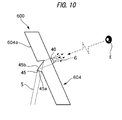
Fig. 10 , in thevehicle display device 600 of Example 7, only a portion of the configuration of atransparent body 604a of adisplay screen 604 differs, and the remaining configuration is similar to the configuration of each of Examples 1 to 4. - Namely, in the
vehicle display device 600 of Example 7, aprism portion 45 formed of a triangular cross-section shaped prism with afirst face 45a and asecond face 45b is provided to a face of the plate shapedtransparent body 604a at the opposite side to the side of the driver. - The
first face 45a of theprism portion 45 extends in a direction perpendicular to the progression direction of the illuminating light 5 entering theprism portion 45 from theprojector 3, and the entering illuminating light 5 is directed toward thesecond face 45b without being refracted. The entering illuminating light undergoes total reflection at thesecond face 45b, and is directed toward thedisplay styling portion 40. Theprism portion 45 corresponds to a light guiding unit of the invention. - In addition to the advantageous effects of Examples 1 to 4, in the
vehicle display device 600 of Example 7, the direction of light beam of the illuminating light reaching thedisplay styling portion 40 can be made to substantially match the observation direction of the driver, such that the display brightness can be increased. - As explained in Example 4 to Example 7, employing any one of the
light diffusion face 42, thelens face 43, or theprism portions - Explanation follows regarding a
vehicle display device 700 according to an Example 8 of the embodiment. - As illustrated in
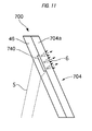
Fig. 11 , in thevehicle display device 700 of Example 8, only the configuration of adisplay screen 704 differs, and the remaining configuration is similar to the configuration of each of Examples 1 to 4. - Namely, in the
vehicle display device 700 of Example 8, thedisplay screen 704a is configured by superimposing and adhering a separate plate shaped secondtransparent body 46 to a face of a plate shaped firsttransparent body 704a at the opposite side to the side of the driver. - A
display styling portion 740 is provided by printing on the illuminating light-incidence face side of the firsttransparent body 704a, and is disposed between the firsttransparent body 704a and the secondtransparent body 46. - In addition to the advantageous effects of Examples 1 to 4, in the
vehicle display device 700 of Example 6, the display styling of thedisplay styling portion 740 appears to the driver to be suspended inside the twotransparent bodies vehicle display device 700 to be increased. - Explanation follows regarding a
vehicle display device 800 according to an Example 9 of the embodiment. - As illustrated in
Fig. 12 , in thevehicle display device 800 of Example 9, only the configuration of adisplay styling portion 840 of adisplay screen 804 differs, and the remaining configuration is similar to the configuration of each of Examples 1 to 4. - Namely,
graduation styling portions 804b of thedisplay styling portion 840 are formed as circular shapes instead of the rectangular bar shapes in the above-described Examples. - Employing various kinds of styling in the display styling portion 40 (140, 740, 840) enables unexpected and interesting display styling, thereby enabling the marketability of the vehicle display device 10 (100 to 800) to be increased.
- Note that the display styling portion 40 (140, 740, 840) is not limited to a rectangular bar shape or a circular shape, and other shapes may be employed.
- The embodiment has been explained based on each of the above Examples, however the embodiment is not limited to these Examples, and design modifications and the like within a range not departing from the spirit of the embodiment are included in the embodiment.
- For example, the vehicle display device 10 (100 to 800) of the embodiment is not limited to a speedometer, and may be applied to display devices displaying other display contents. In such cases, the display styling is obviously configured to match the display contents in each case.
- Moreover, illumination by the
projector 3 may be configured to repeatedly flash. - The present application is based on Japanese Patent Application (No.
2012-164354 -
- 1
- windshield
- 2
- dashboard
- 2a
- opening
- 3
- projector (illumination unit)
- 4
- display screen (combiner)
- 4a
- transparent body (transparent region portion)
- 40
- display styling portion
- 4a
- transparent body (transparent region portion)
- 4b
- graduation styling portion (first display styling portion)
- 4c
- near periphery
- 4d
- numerical symbol styling portion (first display styling portion)
- 5
- illuminating light
- 6
- display light
- 7
- driver's seat
- 8a
- outer circumferential side portion
- 8b
- inner circumferential side portion
- 10
- vehicle display device
- 41a
- arbitrary display styling portion (second display styling portion)
- 42
- light diffusion face
- 43
- lens face
- 44, 45
- prism portion
- 45a
- first face
- 45b
- second face
- 46
- second transparent body (transparent region portion)
- 704a
- first transparent body
Claims (6)
- A vehicle display device comprising:a combiner, provided between a windshield and a driver's seat, including a transparent region portion and a display styling portion including a light diffusion function; andan illuminating unit configured to selectively illuminate the display styling portion and a transparent region portion at the periphery of the display styling portion.
- The vehicle display device according to Claim 1, wherein:the illuminating unit causes a difference in at least one out of a brightness difference or a display color between the display styling portion, and an overall display area of the combiner excluding the display styling portion, and selectively illuminates.
- The vehicle display device according to Claim 1 or 2, wherein:a forming position of one portion of the display styling portion differs to a forming position of another portion of the display styling portion in a thickness direction of the combiner.
- The vehicle display device according to any one of Claims 1 to 3, wherein:the display styling portion includes a first display styling portion, and a second display styling portion which arbitrarily displays display contents different from display contents displayed by the first display styling portion at a different position to the first display styling portion.
- The vehicle display device according to any one of Claims 1 to 4, further comprising:a light guiding unit which directs light emitted from the illuminating unit toward the display styling portion.
- The vehicle display device according to Claim 5, wherein:the light guiding unit is provided to a light-incidence face of the combiner, and is a light diffusion face, a lens, or a prism.
Applications Claiming Priority (2)
| Application Number | Priority Date | Filing Date | Title |
|---|---|---|---|
| JP2012164354A JP5871739B2 (en) | 2012-07-25 | 2012-07-25 | Vehicle display device |
| PCT/JP2013/060686 WO2014017129A1 (en) | 2012-07-25 | 2013-04-09 | Display device for vehicle |
Publications (2)
| Publication Number | Publication Date |
|---|---|
| EP2865556A1 true EP2865556A1 (en) | 2015-04-29 |
| EP2865556A4 EP2865556A4 (en) | 2017-01-04 |
Family
ID=49996948
Family Applications (1)
| Application Number | Title | Priority Date | Filing Date |
|---|---|---|---|
| EP13823702.9A Withdrawn EP2865556A4 (en) | 2012-07-25 | 2013-04-09 | Display device for vehicle |
Country Status (4)
| Country | Link |
|---|---|
| US (1) | US9862274B2 (en) |
| EP (1) | EP2865556A4 (en) |
| JP (1) | JP5871739B2 (en) |
| WO (1) | WO2014017129A1 (en) |
Families Citing this family (3)
| Publication number | Priority date | Publication date | Assignee | Title |
|---|---|---|---|---|
| US10298890B2 (en) * | 2013-06-14 | 2019-05-21 | Denso Corporation | Vehicle display device |
| JP6582642B2 (en) * | 2014-08-11 | 2019-10-02 | セイコーエプソン株式会社 | Vehicular imaging device, vehicular imaging display system, and vehicle |
| JP2019018718A (en) * | 2017-07-18 | 2019-02-07 | 矢崎総業株式会社 | Vehicular display system |
Family Cites Families (34)
| Publication number | Priority date | Publication date | Assignee | Title |
|---|---|---|---|---|
| US3508520A (en) * | 1967-09-13 | 1970-04-28 | Philco Ford Corp | Tuning indicator |
| US3574283A (en) * | 1967-12-27 | 1971-04-13 | William R Albers | A numeric collimated display including means for projecting elevation, attitude and speed information |
| GB1577921A (en) * | 1976-04-06 | 1980-10-29 | Smiths Industries Ltd | Display apparatus |
| US5313292A (en) * | 1987-06-12 | 1994-05-17 | Flight Dynamics | Windshield display system for an automobile |
| DE69224639T2 (en) * | 1991-05-09 | 1998-07-23 | Nu Tech And Engineering Inc | DEVICE FOR INSTRUMENT DISPLAY IN A CAR |
| JPH0728999Y2 (en) | 1991-05-29 | 1995-07-05 | セントラル硝子株式会社 | Glass for multicolor display head-up display |
| JPH0526590U (en) * | 1991-09-25 | 1993-04-06 | 矢崎総業株式会社 | Vehicle display |
| US7126583B1 (en) * | 1999-12-15 | 2006-10-24 | Automotive Technologies International, Inc. | Interactive vehicle display system |
| WO1996002862A1 (en) * | 1994-07-15 | 1996-02-01 | Matsushita Electric Industrial Co., Ltd. | Head-up display apparatus, liquid crystal display panel and production method thereof |
| JPH0891094A (en) * | 1994-09-26 | 1996-04-09 | Asahi Glass Co Ltd | Vehicle display system |
| JPH08113059A (en) * | 1994-10-14 | 1996-05-07 | Asahi Glass Co Ltd | Head-up display device for vehicle |
| JPH0933856A (en) * | 1995-07-24 | 1997-02-07 | Denso Corp | Display device |
| TW393582B (en) * | 1995-12-05 | 2000-06-11 | Matsushita Electric Ind Co Ltd | Backlighting device and color display device |
| US20020154349A1 (en) * | 1997-02-07 | 2002-10-24 | Eads Deutschland Gmbh | Holographic display screen and method for producing the screen |
| CA2308134A1 (en) * | 1997-11-03 | 1999-05-14 | John A. Ayres | Improved gauge instrument for use in a motor vehicle |
| JP2000203308A (en) * | 1999-01-14 | 2000-07-25 | Nissan Motor Co Ltd | Vehicular indication device |
| JP2000276079A (en) * | 1999-03-23 | 2000-10-06 | Harness Syst Tech Res Ltd | Display device |
| US6535333B1 (en) * | 2000-11-21 | 2003-03-18 | 3M Innovative Properties Company | Optical system with reduced color shift |
| US20080024463A1 (en) * | 2001-02-22 | 2008-01-31 | Timothy Pryor | Reconfigurable tactile control display applications |
| US7253723B2 (en) * | 2003-05-19 | 2007-08-07 | Donnelly Corporation | Mirror assembly |
| JPWO2005023598A1 (en) * | 2003-09-02 | 2006-11-02 | 松下電器産業株式会社 | Input device |
| IL165376A0 (en) * | 2003-12-02 | 2006-01-15 | Electro Optics Ind Ltd | Vehicle display system |
| US20060103590A1 (en) * | 2004-10-21 | 2006-05-18 | Avner Divon | Augmented display system and methods |
| JP2006201038A (en) * | 2005-01-20 | 2006-08-03 | Denso Corp | Display device |
| EP1880243A2 (en) * | 2005-05-11 | 2008-01-23 | E.I. Dupont De Nemours And Company | Polymeric interlayers having a wedge profile |
| US7874689B2 (en) * | 2006-10-03 | 2011-01-25 | Denso Corporation | Display device |
| US20100066645A1 (en) * | 2006-11-29 | 2010-03-18 | Mikio Ishii | High visibility head-up display system |
| US7413233B1 (en) * | 2007-08-28 | 2008-08-19 | Man-Young Jung | Vehicle sun visor with auto-shading prompter screen |
| JP4536766B2 (en) * | 2007-10-19 | 2010-09-01 | 株式会社デンソー | Display device |
| JP5542836B2 (en) * | 2008-12-09 | 2014-07-09 | デルファイ・テクノロジーズ・インコーポレーテッド | A diffractive head-up display device with a device for adjusting the position of a virtual image |
| JP2010143520A (en) * | 2008-12-22 | 2010-07-01 | Toshiba Corp | On-board display system and display method |
| JP2010262161A (en) * | 2009-05-08 | 2010-11-18 | Toshiba Corp | Display, display method and vehicle |
| JP6163033B2 (en) * | 2013-07-10 | 2017-07-12 | 矢崎総業株式会社 | Head-up display device and display unit |
| JP6209378B2 (en) * | 2013-07-10 | 2017-10-04 | 矢崎総業株式会社 | Display unit |
-
2012
- 2012-07-25 JP JP2012164354A patent/JP5871739B2/en not_active Expired - Fee Related
-
2013
- 2013-04-09 US US14/415,959 patent/US9862274B2/en not_active Expired - Fee Related
- 2013-04-09 WO PCT/JP2013/060686 patent/WO2014017129A1/en active Application Filing
- 2013-04-09 EP EP13823702.9A patent/EP2865556A4/en not_active Withdrawn
Also Published As
| Publication number | Publication date |
|---|---|
| EP2865556A4 (en) | 2017-01-04 |
| JP2014026018A (en) | 2014-02-06 |
| WO2014017129A1 (en) | 2014-01-30 |
| JP5871739B2 (en) | 2016-03-01 |
| US20150183322A1 (en) | 2015-07-02 |
| US9862274B2 (en) | 2018-01-09 |
Similar Documents
| Publication | Publication Date | Title |
|---|---|---|
| US20200156531A1 (en) | Timing control unit for controlling an illumination device with coherent light source | |
| JP2007108429A (en) | Display device and headup display device for vehicle equipped therewith | |
| US9902308B2 (en) | Vehicle lighting system | |
| US9423614B2 (en) | Head-up display device | |
| WO2014199629A1 (en) | Display device for vehicle | |
| JP2002287076A (en) | Display device for vehicle | |
| KR101798518B1 (en) | Instrument panel having stereophonic light for vehicle | |
| US6404333B1 (en) | Gauge instrument for use in a motor vehicle | |
| US10539294B2 (en) | Automobile exterior rear view mirror blind spot warning indication device | |
| JP2009222881A (en) | Head-up display device | |
| US9862274B2 (en) | Display device for vehicle | |
| CN113375119A (en) | Light emitting device for vehicle | |
| CN107531156B (en) | Display device for vehicle | |
| US20150003090A1 (en) | Structural and effect-generating fabric as a light-scattering element in optical systems | |
| JP2009069087A (en) | Display apparatus | |
| US10818205B2 (en) | Lamp assembly | |
| WO2023199884A1 (en) | Vehicle lamp | |
| JP4652787B2 (en) | Display device | |
| WO2023199897A1 (en) | Information presentation device | |
| JP7433716B2 (en) | heads up display device | |
| US10807472B2 (en) | Vehicular display device | |
| US20230150417A1 (en) | Lighting device for a motor vehicle | |
| US20240102627A1 (en) | Road surface rendering device | |
| JP2006113024A (en) | Pointing instrument | |
| EP3174035A1 (en) | Light-emitting device |
Legal Events
| Date | Code | Title | Description |
|---|---|---|---|
| PUAI | Public reference made under article 153(3) epc to a published international application that has entered the european phase |
Free format text: ORIGINAL CODE: 0009012 |
|
| 17P | Request for examination filed |
Effective date: 20150123 |
|
| AK | Designated contracting states |
Kind code of ref document: A1 Designated state(s): AL AT BE BG CH CY CZ DE DK EE ES FI FR GB GR HR HU IE IS IT LI LT LU LV MC MK MT NL NO PL PT RO RS SE SI SK SM TR |
|
| AX | Request for extension of the european patent |
Extension state: BA ME |
|
| DAX | Request for extension of the european patent (deleted) | ||
| RA4 | Supplementary search report drawn up and despatched (corrected) |
Effective date: 20161202 |
|
| RIC1 | Information provided on ipc code assigned before grant |
Ipc: B60R 11/02 20060101ALI20161128BHEP Ipc: G02B 27/01 20060101ALI20161128BHEP Ipc: B60K 35/00 20060101AFI20161128BHEP |
|
| STAA | Information on the status of an ep patent application or granted ep patent |
Free format text: STATUS: THE APPLICATION HAS BEEN WITHDRAWN |
|
| 18W | Application withdrawn |
Effective date: 20190527 |