EP2865539A2 - Bearing assembly with safety bushing, and insertion method - Google Patents
Bearing assembly with safety bushing, and insertion method Download PDFInfo
- Publication number
- EP2865539A2 EP2865539A2 EP13807351.5A EP13807351A EP2865539A2 EP 2865539 A2 EP2865539 A2 EP 2865539A2 EP 13807351 A EP13807351 A EP 13807351A EP 2865539 A2 EP2865539 A2 EP 2865539A2
- Authority
- EP
- European Patent Office
- Prior art keywords
- hub
- safety bushing
- bushing
- assembled
- safety
- Prior art date
- Legal status (The legal status is an assumption and is not a legal conclusion. Google has not performed a legal analysis and makes no representation as to the accuracy of the status listed.)
- Granted
Links
Images


Classifications
-
- F—MECHANICAL ENGINEERING; LIGHTING; HEATING; WEAPONS; BLASTING
- F16—ENGINEERING ELEMENTS AND UNITS; GENERAL MEASURES FOR PRODUCING AND MAINTAINING EFFECTIVE FUNCTIONING OF MACHINES OR INSTALLATIONS; THERMAL INSULATION IN GENERAL
- F16C—SHAFTS; FLEXIBLE SHAFTS; ELEMENTS OR CRANKSHAFT MECHANISMS; ROTARY BODIES OTHER THAN GEARING ELEMENTS; BEARINGS
- F16C19/00—Bearings with rolling contact, for exclusively rotary movement
- F16C19/22—Bearings with rolling contact, for exclusively rotary movement with bearing rollers essentially of the same size in one or more circular rows, e.g. needle bearings
- F16C19/34—Bearings with rolling contact, for exclusively rotary movement with bearing rollers essentially of the same size in one or more circular rows, e.g. needle bearings for both radial and axial load
- F16C19/36—Bearings with rolling contact, for exclusively rotary movement with bearing rollers essentially of the same size in one or more circular rows, e.g. needle bearings for both radial and axial load with a single row of rollers
- F16C19/364—Bearings with rolling contact, for exclusively rotary movement with bearing rollers essentially of the same size in one or more circular rows, e.g. needle bearings for both radial and axial load with a single row of rollers with tapered rollers, i.e. rollers having essentially the shape of a truncated cone
-
- B—PERFORMING OPERATIONS; TRANSPORTING
- B60—VEHICLES IN GENERAL
- B60B—VEHICLE WHEELS; CASTORS; AXLES FOR WHEELS OR CASTORS; INCREASING WHEEL ADHESION
- B60B27/00—Hubs
- B60B27/001—Hubs with roller-bearings
-
- B—PERFORMING OPERATIONS; TRANSPORTING
- B60—VEHICLES IN GENERAL
- B60B—VEHICLE WHEELS; CASTORS; AXLES FOR WHEELS OR CASTORS; INCREASING WHEEL ADHESION
- B60B27/00—Hubs
- B60B27/0078—Hubs characterised by the fixation of bearings
-
- B—PERFORMING OPERATIONS; TRANSPORTING
- B60—VEHICLES IN GENERAL
- B60B—VEHICLE WHEELS; CASTORS; AXLES FOR WHEELS OR CASTORS; INCREASING WHEEL ADHESION
- B60B27/00—Hubs
- B60B27/02—Hubs adapted to be rotatably arranged on axle
-
- F—MECHANICAL ENGINEERING; LIGHTING; HEATING; WEAPONS; BLASTING
- F16—ENGINEERING ELEMENTS AND UNITS; GENERAL MEASURES FOR PRODUCING AND MAINTAINING EFFECTIVE FUNCTIONING OF MACHINES OR INSTALLATIONS; THERMAL INSULATION IN GENERAL
- F16C—SHAFTS; FLEXIBLE SHAFTS; ELEMENTS OR CRANKSHAFT MECHANISMS; ROTARY BODIES OTHER THAN GEARING ELEMENTS; BEARINGS
- F16C19/00—Bearings with rolling contact, for exclusively rotary movement
- F16C19/22—Bearings with rolling contact, for exclusively rotary movement with bearing rollers essentially of the same size in one or more circular rows, e.g. needle bearings
- F16C19/34—Bearings with rolling contact, for exclusively rotary movement with bearing rollers essentially of the same size in one or more circular rows, e.g. needle bearings for both radial and axial load
- F16C19/38—Bearings with rolling contact, for exclusively rotary movement with bearing rollers essentially of the same size in one or more circular rows, e.g. needle bearings for both radial and axial load with two or more rows of rollers
- F16C19/383—Bearings with rolling contact, for exclusively rotary movement with bearing rollers essentially of the same size in one or more circular rows, e.g. needle bearings for both radial and axial load with two or more rows of rollers with tapered rollers, i.e. rollers having essentially the shape of a truncated cone
- F16C19/385—Bearings with rolling contact, for exclusively rotary movement with bearing rollers essentially of the same size in one or more circular rows, e.g. needle bearings for both radial and axial load with two or more rows of rollers with tapered rollers, i.e. rollers having essentially the shape of a truncated cone with two rows, i.e. double-row tapered roller bearings
- F16C19/386—Bearings with rolling contact, for exclusively rotary movement with bearing rollers essentially of the same size in one or more circular rows, e.g. needle bearings for both radial and axial load with two or more rows of rollers with tapered rollers, i.e. rollers having essentially the shape of a truncated cone with two rows, i.e. double-row tapered roller bearings in O-arrangement
-
- F—MECHANICAL ENGINEERING; LIGHTING; HEATING; WEAPONS; BLASTING
- F16—ENGINEERING ELEMENTS AND UNITS; GENERAL MEASURES FOR PRODUCING AND MAINTAINING EFFECTIVE FUNCTIONING OF MACHINES OR INSTALLATIONS; THERMAL INSULATION IN GENERAL
- F16C—SHAFTS; FLEXIBLE SHAFTS; ELEMENTS OR CRANKSHAFT MECHANISMS; ROTARY BODIES OTHER THAN GEARING ELEMENTS; BEARINGS
- F16C19/00—Bearings with rolling contact, for exclusively rotary movement
- F16C19/54—Systems consisting of a plurality of bearings with rolling friction
- F16C19/541—Systems consisting of juxtaposed rolling bearings including at least one angular contact bearing
- F16C19/542—Systems consisting of juxtaposed rolling bearings including at least one angular contact bearing with two rolling bearings with angular contact
- F16C19/543—Systems consisting of juxtaposed rolling bearings including at least one angular contact bearing with two rolling bearings with angular contact in O-arrangement
-
- F—MECHANICAL ENGINEERING; LIGHTING; HEATING; WEAPONS; BLASTING
- F16—ENGINEERING ELEMENTS AND UNITS; GENERAL MEASURES FOR PRODUCING AND MAINTAINING EFFECTIVE FUNCTIONING OF MACHINES OR INSTALLATIONS; THERMAL INSULATION IN GENERAL
- F16C—SHAFTS; FLEXIBLE SHAFTS; ELEMENTS OR CRANKSHAFT MECHANISMS; ROTARY BODIES OTHER THAN GEARING ELEMENTS; BEARINGS
- F16C33/00—Parts of bearings; Special methods for making bearings or parts thereof
- F16C33/72—Sealings
- F16C33/76—Sealings of ball or roller bearings
- F16C33/768—Sealings of ball or roller bearings between relatively stationary parts, i.e. static seals
-
- F—MECHANICAL ENGINEERING; LIGHTING; HEATING; WEAPONS; BLASTING
- F16—ENGINEERING ELEMENTS AND UNITS; GENERAL MEASURES FOR PRODUCING AND MAINTAINING EFFECTIVE FUNCTIONING OF MACHINES OR INSTALLATIONS; THERMAL INSULATION IN GENERAL
- F16C—SHAFTS; FLEXIBLE SHAFTS; ELEMENTS OR CRANKSHAFT MECHANISMS; ROTARY BODIES OTHER THAN GEARING ELEMENTS; BEARINGS
- F16C35/00—Rigid support of bearing units; Housings, e.g. caps, covers
- F16C35/04—Rigid support of bearing units; Housings, e.g. caps, covers in the case of ball or roller bearings
- F16C35/06—Mounting or dismounting of ball or roller bearings; Fixing them onto shaft or in housing
- F16C35/067—Fixing them in a housing
-
- F—MECHANICAL ENGINEERING; LIGHTING; HEATING; WEAPONS; BLASTING
- F16—ENGINEERING ELEMENTS AND UNITS; GENERAL MEASURES FOR PRODUCING AND MAINTAINING EFFECTIVE FUNCTIONING OF MACHINES OR INSTALLATIONS; THERMAL INSULATION IN GENERAL
- F16C—SHAFTS; FLEXIBLE SHAFTS; ELEMENTS OR CRANKSHAFT MECHANISMS; ROTARY BODIES OTHER THAN GEARING ELEMENTS; BEARINGS
- F16C41/00—Other accessories, e.g. devices integrated in the bearing not relating to the bearing function as such
- F16C41/04—Preventing damage to bearings during storage or transport thereof or when otherwise out of use
-
- F—MECHANICAL ENGINEERING; LIGHTING; HEATING; WEAPONS; BLASTING
- F16—ENGINEERING ELEMENTS AND UNITS; GENERAL MEASURES FOR PRODUCING AND MAINTAINING EFFECTIVE FUNCTIONING OF MACHINES OR INSTALLATIONS; THERMAL INSULATION IN GENERAL
- F16C—SHAFTS; FLEXIBLE SHAFTS; ELEMENTS OR CRANKSHAFT MECHANISMS; ROTARY BODIES OTHER THAN GEARING ELEMENTS; BEARINGS
- F16C43/00—Assembling bearings
- F16C43/04—Assembling rolling-contact bearings
- F16C43/045—Mounting or replacing seals
-
- F—MECHANICAL ENGINEERING; LIGHTING; HEATING; WEAPONS; BLASTING
- F16—ENGINEERING ELEMENTS AND UNITS; GENERAL MEASURES FOR PRODUCING AND MAINTAINING EFFECTIVE FUNCTIONING OF MACHINES OR INSTALLATIONS; THERMAL INSULATION IN GENERAL
- F16C—SHAFTS; FLEXIBLE SHAFTS; ELEMENTS OR CRANKSHAFT MECHANISMS; ROTARY BODIES OTHER THAN GEARING ELEMENTS; BEARINGS
- F16C2326/00—Articles relating to transporting
- F16C2326/01—Parts of vehicles in general
- F16C2326/02—Wheel hubs or castors
Definitions
- this description relates to a bearing assembly with safety bushing and insertion method, comprising two pre-assembled tapered roller bearing units that can be replaced on the wheel hub of commercial vehicles.
- Each unit comprises an outer ring and an inner ring, with several tapered rollers in a cage and an identifying box securing the outer ring between them, as well as comprising a safety bushing, similar in size to the pre-assembled units, fitted between the inner and outer rings and making up a compact assembly that can be used as a tool for mounting the pre-assembled units on the hub and for mounting the retainers in the cavity between the inner ring and the hub.
- a seal is fitted on one of the pre-assembled units through a four-step process.
- tapered roller bearings comprising an outer ring, an inner ring, a cage with several tapered rollers, a box and a seal, which are mounted on the wheel hub of industrial vehicles in different ways depending on roller bearing configuration.
- One of these includes using simple tools without any dedicated requirements, inserting the outer ring in the wheel hub in the corresponding box; this is repeated on the opposite side of the hub.
- the cage with tapered rollers is inserted into the outer ring of one of the sides; this is repeated on the opposite side.
- the inner ring is inserted into one of the sides and this is repeated on the opposite side.
- a seal connecting both inner rings by their inside diameter is inserted.
- the disadvantage of this type of assembly is that it takes nine steps, mainly using non-dedicated tools, increasing assembly times and the corresponding cost in labour.
- a bearing assembly with safety bushing and insertion method comprises a safety bushing between the inner and outer rings of each one of the pre-assembled units making up an easy-to-handle compact assembly and avoiding contact with several tapered rollers located in the cage between the inner and outer rings, hence preventing blows and scratches during transport.
- the safety bushing also protects the pre-assembled units from contamination factors while being stored and mounted on the hub, which is done in four steps because the tool used is suitable for this type of assembly.
- the safety bushing is similar in size to the pre-assembled units and consists of four different surfaces: thrust surface of the outer ring and retainer, axially connecting with the outer ring, moves the pre-assembled unit during assembly and can also be used to axially insert the retainer into the hub; regulator surface that axially secures the safety bushing (8) to the inner ring; drive-up surface that can also be used to axially insert the retainer into the hub; and extraction surface which can be enabled as an option once it has been used as an assembly tool.
- the identifying box includes a code that identifies the location of the pre-assembled units on the hub.
- the seal consists of a gasket between the inner rings of a bearing, as claimed in Spanish Utility Model U201030569 .
- the seal between the inner rings consists of a U-shaped bushing made of metal or a synthetic material, with an O-ring around its inside diameter.
- the seal is pre-assembled on one of the pre-assembled units only to facilitate later mounting both units on the hub.
- This bearing assembly with safety bushing offers many advantages over the bearings currently available. The most important one is that thanks to the configuration of the safety bushing, similar in size to the pre-assembled units, it can be used as a tool for mounting the bearing on the hub and for mounting the retainers in the cavity between the inner ring and the hub through a four-step assembly process.
- the safety bushing prevents contact with several tapered rollers between the inner and outer rings, protecting from blows and scratches during transport as well as from contamination factors during storage and mounting on the hub.
- the identifying box includes a code that identifies the location of the pre-assembled units on the hub.
- the seal consists of a gasket or an alternative embodiment of a U-shaped bushing with an O-ring.
- the bearing assembly with safety bushing comprises two pre-assembled units (1, 1.1) that can be replaced on the wheel hub (9) of commercial vehicles.
- Each unit comprises an outer ring (2, 2.1) and an inner ring (3, 3.1), with several tapered rollers (4, 4.1) in a cage and an identifying box (6, 6.1) axially securing the outer ring (2, 2.1), as well as a safety bushing (8) that is a ring similar in size to the pre-assembled units (1, 1.1), fitted between the outer ring (2, 2.1) and the inner ring (3, 3.1), making up a compact assembly that can be used as a tool for mounting the pre-assembled units on the hub (9) and for mounting the retainers (5, 5.1) in the cavity between the pre-assembled unit and the hub (9).
- the safety bushing consists of four different surfaces: thrust surface (10) of the outer ring (2, 2.1) and retainer (5, 5.1), axially connecting with the outer ring (2, 2.1). This surface moves the pre-assembled units (1, 1.1) and can also be used to axially insert the retainer (5, 5.1) into the hub (9).
- a regulator surface (11) that axially secures the safety bushing (8) to the inner ring (3, 3.1).
- a drive-up surface (12) that can also be used to axially insert the retainer (5, 5.1) into the hub (9).
- the identifying box (6, 6.1) includes a code that identifies the location of the pre-assembled units (1, 1.1) on the hub (9).
- the seal (7) consists of a gasket between the inner rings of a bearing, as claimed in Spanish Utility Model U201030569 .
- the seal (7) between inner rings consists of a U-shaped bushing (14) with an O-ring (15) around its inside diameter.
- a pre-assembled unit (1) is inserted, by the thrust surface (10) of the safety bushing(8); this is repeated for the other pre-assembled unit (1.1) reversely and on the opposite side.
- the inner rings are now facing (3, 3.1), or set together through a seal (7, 7.1).
- a retainer (5.1) is inserted in the cavity between the inner ring (3.1) of the pre-assembled unit (1.1) and the hub (9), by the drive-up surface (12) of the safety bushing (8); this is repeated on the opposite side for the insertion of the retainer (5).
- the seal (7, 7.1) is pre-assembled on one of the pre-assembled units (1, 1.1) to facilitate lamounting both units on the hub (9).
Landscapes
- Engineering & Computer Science (AREA)
- General Engineering & Computer Science (AREA)
- Mechanical Engineering (AREA)
- Rolling Contact Bearings (AREA)
- Mounting Of Bearings Or Others (AREA)
Abstract
Description
- As indicated in the title, this description relates to a bearing assembly with safety bushing and insertion method, comprising two pre-assembled tapered roller bearing units that can be replaced on the wheel hub of commercial vehicles. Each unit comprises an outer ring and an inner ring, with several tapered rollers in a cage and an identifying box securing the outer ring between them, as well as comprising a safety bushing, similar in size to the pre-assembled units, fitted between the inner and outer rings and making up a compact assembly that can be used as a tool for mounting the pre-assembled units on the hub and for mounting the retainers in the cavity between the inner ring and the hub. In addition, a seal is fitted on one of the pre-assembled units through a four-step process.
- Currently, there is a wide range of tapered roller bearings comprising an outer ring, an inner ring, a cage with several tapered rollers, a box and a seal, which are mounted on the wheel hub of industrial vehicles in different ways depending on roller bearing configuration.
- One of these includes using simple tools without any dedicated requirements, inserting the outer ring in the wheel hub in the corresponding box; this is repeated on the opposite side of the hub. Next, the cage with tapered rollers is inserted into the outer ring of one of the sides; this is repeated on the opposite side. Then, the inner ring is inserted into one of the sides and this is repeated on the opposite side. Following, a seal connecting both inner rings by their inside diameter is inserted. The disadvantage of this type of assembly is that it takes nine steps, mainly using non-dedicated tools, increasing assembly times and the corresponding cost in labour.
- In order to reduce the number of steps during assembly and the cost of labour in patent
WO2007115539 , a tapered roller bearing with a cylindrical extension of the outer rings is introduced, so that retainers are below the extension level. This assembly is done with non-dedicated tools but the steps are reduced to three, inserting a roller bearing with all of its components on one side of the hub, and repeating on the opposite side. Next, a safety ring is inserted connecting both inner rings at their inside diameter. The disadvantage is that although the number of assembly steps is significantly reduced, using non-dedicated tools may increase assembly times. - In order to facilitate mounting roller bearings on wheel hubs, a bearing assembly with safety bushing and insertion method has been devised. It comprises a safety bushing between the inner and outer rings of each one of the pre-assembled units making up an easy-to-handle compact assembly and avoiding contact with several tapered rollers located in the cage between the inner and outer rings, hence preventing blows and scratches during transport. The safety bushing also protects the pre-assembled units from contamination factors while being stored and mounted on the hub, which is done in four steps because the tool used is suitable for this type of assembly.
- The safety bushing is similar in size to the pre-assembled units and consists of four different surfaces: thrust surface of the outer ring and retainer, axially connecting with the outer ring, moves the pre-assembled unit during assembly and can also be used to axially insert the retainer into the hub; regulator surface that axially secures the safety bushing (8) to the inner ring; drive-up surface that can also be used to axially insert the retainer into the hub; and extraction surface which can be enabled as an option once it has been used as an assembly tool..
- The identifying box includes a code that identifies the location of the pre-assembled units on the hub.
- The seal consists of a gasket between the inner rings of a bearing, as claimed in Spanish Utility Model
U201030569 - In an alternative embodiment, the seal between the inner rings consists of a U-shaped bushing made of metal or a synthetic material, with an O-ring around its inside diameter.
- It is a four-step assembly process. After cleaning the hub, a pre-assembled unit is inserted, by the thrust surface of the safety bushing; this is repeated for the other pre-assembled unit reversely and on the opposite side. The inner rings are now facing, or set together through a seal. Next, a retainer is inserted in the cavity between the inner ring of the pre-assembled unit and the hub, by the safety bushing drive-up surface; this is repeated on the opposite side.
- The seal is pre-assembled on one of the pre-assembled units only to facilitate later mounting both units on the hub.
- This bearing assembly with safety bushing offers many advantages over the bearings currently available. The most important one is that thanks to the configuration of the safety bushing, similar in size to the pre-assembled units, it can be used as a tool for mounting the bearing on the hub and for mounting the retainers in the cavity between the inner ring and the hub through a four-step assembly process.
- Another important advantage is that the safety bushing prevents contact with several tapered rollers between the inner and outer rings, protecting from blows and scratches during transport as well as from contamination factors during storage and mounting on the hub.
- Another advantage of this invention is that the identifying box includes a code that identifies the location of the pre-assembled units on the hub.
- Another significant advantage is that retainers are inserted separately into the cavity between the pre-assembled unit and the hub.
- Finally, it is worth mentioning that the seal consists of a gasket or an alternative embodiment of a U-shaped bushing with an O-ring.
- In order to better understand the current invention, a preferred practical embodiment is provided in the enclosed drawings.
- Among the drawings,
- figure -1- shows a section view of the bearing assembly with safety bushing. A seal is fitted on one of the pre-assembled units, showing a retainer next to one of the pre-assembled units.
- figure -2- shows an elevation and plan view of the safety bushing.
- Figure -3- shows a section view of the hub with a pre-assembled unit, corresponding to the first step of the insertion method. It also shows the position of the safety bushing with its thrust surface on the outer ring of the pre-assembled unit, shown with seal.
- Figure -4- shows a section view of the hub with a pre-assembled unit, on the opposite side of the hub, corresponding to the first step of the insertion method. It also shows the position of the safety bushing with its thrust surface on the outer ring of the pre-assembled unit, connected by the inner rings through the seal, in this case.
- Figure -5- shows a section view of the hub with a retainer in the cavity between the pre-assembled unit and the hub, corresponding to the third step of the insertion method. It also shows the position of the safety bushing with its drive-up surface for insertion.
- Figure -6- shows a section view of the hub with a retainer in the cavity between the pre-assembled unit and the hub, on the opposite side of the hub, corresponding to the fourth step of the insertion method. It also shows the position of the safety bushing with its drive-up surface for insertion.
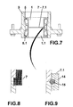
- Figure -7- shows a section view of the hub with the inserted bearing assembly.
- Figure -8- shows a design detail of the seal consisting of a gasket, as claimed in Spanish Utility Model
U201030569 - Figure -9- shows a design detail of an alternative embodiment of the seal consisting of a U-shaped bushing with an O-ring around its inside diameter.
- The bearing assembly with safety bushing comprises two pre-assembled units (1, 1.1) that can be replaced on the wheel hub (9) of commercial vehicles. Each unit comprises an outer ring (2, 2.1) and an inner ring (3, 3.1), with several tapered rollers (4, 4.1) in a cage and an identifying box (6, 6.1) axially securing the outer ring (2, 2.1), as well as a safety bushing (8) that is a ring similar in size to the pre-assembled units (1, 1.1), fitted between the outer ring (2, 2.1) and the inner ring (3, 3.1), making up a compact assembly that can be used as a tool for mounting the pre-assembled units on the hub (9) and for mounting the retainers (5, 5.1) in the cavity between the pre-assembled unit and the hub (9).
- The safety bushing consists of four different surfaces: thrust surface (10) of the outer ring (2, 2.1) and retainer (5, 5.1), axially connecting with the outer ring (2, 2.1). This surface moves the pre-assembled units (1, 1.1) and can also be used to axially insert the retainer (5, 5.1) into the hub (9).
- A regulator surface (11) that axially secures the safety bushing (8) to the inner ring (3, 3.1). A drive-up surface (12) that can also be used to axially insert the retainer (5, 5.1) into the hub (9).
- And finally, the extraction surface (13) of the safety bushing (8), which can be enabled as an option once it has been used as an assembly tool.
- The identifying box (6, 6.1) includes a code that identifies the location of the pre-assembled units (1, 1.1) on the hub (9).
- The seal (7) consists of a gasket between the inner rings of a bearing, as claimed in Spanish Utility Model
U201030569 - In an alternative embodiment, the seal (7) between inner rings consists of a U-shaped bushing (14) with an O-ring (15) around its inside diameter.
- Mounting a tapered roller bearing assembly on a wheel hub is done in four steps:
- After cleaning the hub (9), a pre-assembled unit (1) is inserted, by the thrust surface (10) of the safety bushing(8); this is repeated for the other pre-assembled unit (1.1) reversely and on the opposite side. The inner rings are now facing (3, 3.1), or set together through a seal (7, 7.1). Next, a retainer (5.1) is inserted in the cavity between the inner ring (3.1) of the pre-assembled unit (1.1) and the hub (9), by the drive-up surface (12) of the safety bushing (8); this is repeated on the opposite side for the insertion of the retainer (5).
- The seal (7, 7.1) is pre-assembled on one of the pre-assembled units (1, 1.1) to facilitate lamounting both units on the hub (9).
Claims (10)
- Bearing assembly with safety bushing comprising two pre-assembled units (1, 1.1) that can be replaced on the wheel hub (9) of commercial vehicles. Each one comprises- an outer ring (2, 2.1)- an inner ring (3, 3.1), with several tapered rollers (4 & 4.1) between them in a cage,- an identifying box (6, 6.1) axially securing the outer ring (2, 2.1); the bearing assembly with safety bushing comprising: a safety bushing (8) that is a ring similar in size to the pre-assembled units (1, 1.1), made up of four different surfaces: thrust surface (10) of the outer ring (2, 2.1) and retainer (5, 5.1), regulator surface (11) that axially secures the inner ring (3, 3.1), drive-up surface (12) to insert the retainer (5, 5.1) and extraction surface (13) of the safety bushing (8).
- Bearing assembly with safety bushing, according to previous claims, comprising one of the two pre-assembled units (1, 1.1) with seal (7, 7.1)
- Bearing assembly with safety bushing, according to claim 2, comprising a seal (7.1) between inner rings, which consists of a U-shaped bushing (14) with an O-ring (15) around its inside diameter.
- Bearing assembly with safety bushing, according to claim 1, comprising each one of the identifying boxes (6, 6.1) including a code that identifies the location of the tapered roller bearing (1, 1.1) on the hub (9).
- Insertion method of a bearing assembly with safety bushing described according to previous claims, comprising the following four steps:- first, insertion of a pre-assembled unit into the hub (9)- second, insertion of the other pre-assembled unit (1.1) into the hub (9) facing the previous one and the corresponding inner rings (3, 3.1)- third, insertion of the retainer (5.1)- fourth, insertion of the retainer (5)
- Insertion method, according to claim 5, comprising a first step in which, after cleaning the hub (9), a pre-assembled unit (1) is inserted, by the thrust surface (10) of the safety bushing (8) on the outer ring (2) of the pre-assembled unit (1), with a seal (7, 7.1) fitted on the inside diameter of the inner ring (3), in this case.
- Insertion method, according to claim 5, comprising a second step in which the other pre-assembled unit (1.1) is inserted into the opposite side of the hub (9), by the thrust surface (10) of the safety bushing (8) on the outer ring (2) of the pre-assembled unit (1.1), with the inner rings (3, 3.1) now facing.
- Insertion method, according to claim 7, comprising the pre-assembled units (1 & 1.1) connected through the seal (7, 7.1).
- Insertion method, according to claim 5, comprising a third step in which a retainer (5.1) is inserted in the cavity between the inner ring (3.1) of the pre-assembled unit (1.1) and the hub (9), by the drive-up surface (12) of the safety bushing (8).
- Insertion method, according to claim 5, comprising a fourth step in which a retainer (5.1) is inserted in the cavity between the inner ring (3.1) of the pre-assembled unit (1.1) and the hub (9), by the drive-up surface (12) of the safety bushing (8).
Priority Applications (1)
| Application Number | Priority Date | Filing Date | Title |
|---|---|---|---|
| PL13807351T PL2865539T3 (en) | 2012-06-20 | 2013-06-19 | Bearing assembly with safety bushing, and insertion method |
Applications Claiming Priority (2)
| Application Number | Priority Date | Filing Date | Title |
|---|---|---|---|
| ES201230966A ES2482567B2 (en) | 2012-06-20 | 2012-06-20 | Bearing assembly with safety bushing and insertion procedure |
| PCT/ES2013/070395 WO2013190160A2 (en) | 2012-06-20 | 2013-06-19 | Bearing assembly with safety bushing, and insertion method |
Publications (3)
| Publication Number | Publication Date |
|---|---|
| EP2865539A2 true EP2865539A2 (en) | 2015-04-29 |
| EP2865539A4 EP2865539A4 (en) | 2015-12-16 |
| EP2865539B1 EP2865539B1 (en) | 2017-08-02 |
Family
ID=49769610
Family Applications (1)
| Application Number | Title | Priority Date | Filing Date |
|---|---|---|---|
| EP13807351.5A Active EP2865539B1 (en) | 2012-06-20 | 2013-06-19 | Bearing assembly with safety bushing, and insertion method |
Country Status (9)
| Country | Link |
|---|---|
| EP (1) | EP2865539B1 (en) |
| CN (1) | CN104428142B (en) |
| BR (1) | BR112014031728B1 (en) |
| CL (1) | CL2014003458A1 (en) |
| ES (2) | ES2482567B2 (en) |
| IN (1) | IN2015MN00136A (en) |
| PL (1) | PL2865539T3 (en) |
| PT (1) | PT2865539T (en) |
| WO (1) | WO2013190160A2 (en) |
Cited By (2)
| Publication number | Priority date | Publication date | Assignee | Title |
|---|---|---|---|---|
| CN108050154A (en) * | 2017-12-18 | 2018-05-18 | 福赛轴承(嘉兴)有限公司 | A kind of heavy-duty vehicle double-row bearing and its pallet |
| CN108180215A (en) * | 2017-12-18 | 2018-06-19 | 福赛轴承(嘉兴)有限公司 | It is a kind of with the heavy-duty vehicle double-row bearing of pallet and installation and method for dismounting |
Families Citing this family (3)
| Publication number | Priority date | Publication date | Assignee | Title |
|---|---|---|---|---|
| ES1124780Y (en) * | 2014-09-09 | 2015-01-27 | Fersa Innova S L U | BEARING ASSEMBLY WITH SAFETY CAP AND OUTDOOR AXIAL CLAMP |
| DE102016211196A1 (en) * | 2016-06-22 | 2017-12-28 | Aktiebolaget Skf | rolling bearing unit |
| US10228017B2 (en) * | 2017-08-10 | 2019-03-12 | Schaeffler Technologies AG & Co. KG | Encapsulated carrier hub and thrust needle bearing assembly |
Family Cites Families (9)
| Publication number | Priority date | Publication date | Assignee | Title |
|---|---|---|---|---|
| DE4235611C2 (en) * | 1992-10-22 | 2000-01-20 | Skf Gmbh | Plastic bearing housing |
| SE506574C2 (en) * | 1996-05-06 | 1998-01-12 | Volvo Lastvagnar Ab | Sealing device for bearing arrangement and arrangement for sealing of bearing device |
| JP4108513B2 (en) * | 2003-03-19 | 2008-06-25 | 本田技研工業株式会社 | Wheel structure and wheel assembling method |
| SE525142C2 (en) * | 2003-05-12 | 2004-12-07 | Volvo Lastvagnar Ab | Bearing and wheel axle arrangements for vehicles |
| DE102006017162A1 (en) * | 2006-04-12 | 2007-10-18 | Schaeffler Kg | Interchangeable wheel bearing unit, for example for commercial vehicles, as well as methods for mounting a wheel bearing unit |
| DE102009027078B4 (en) * | 2009-06-22 | 2015-07-16 | Saf-Holland Gmbh | Wheel bearing for vehicle axles |
| ES2397537T3 (en) * | 2010-06-24 | 2013-03-07 | Schaeffler Technologies Gmbh & Co. Kg | Rolling element bearing unit with split outer ring and transport ring |
| DE102010047141A1 (en) * | 2010-09-30 | 2012-04-05 | Schaeffler Technologies Gmbh & Co. Kg | adapter ring |
| DE102012206659B4 (en) * | 2012-04-23 | 2021-02-25 | Schaeffler Technologies AG & Co. KG | Pre-assembled, press-fit rolling bearing unit |
-
2012
- 2012-06-20 ES ES201230966A patent/ES2482567B2/en not_active Expired - Fee Related
-
2013
- 2013-06-19 PL PL13807351T patent/PL2865539T3/en unknown
- 2013-06-19 ES ES13807351.5T patent/ES2641378T3/en active Active
- 2013-06-19 WO PCT/ES2013/070395 patent/WO2013190160A2/en not_active Ceased
- 2013-06-19 PT PT138073515T patent/PT2865539T/en unknown
- 2013-06-19 EP EP13807351.5A patent/EP2865539B1/en active Active
- 2013-06-19 IN IN136MUN2015 patent/IN2015MN00136A/en unknown
- 2013-06-19 CN CN201380032779.9A patent/CN104428142B/en active Active
- 2013-06-19 BR BR112014031728-3A patent/BR112014031728B1/en active IP Right Grant
-
2014
- 2014-12-19 CL CL2014003458A patent/CL2014003458A1/en unknown
Cited By (2)
| Publication number | Priority date | Publication date | Assignee | Title |
|---|---|---|---|---|
| CN108050154A (en) * | 2017-12-18 | 2018-05-18 | 福赛轴承(嘉兴)有限公司 | A kind of heavy-duty vehicle double-row bearing and its pallet |
| CN108180215A (en) * | 2017-12-18 | 2018-06-19 | 福赛轴承(嘉兴)有限公司 | It is a kind of with the heavy-duty vehicle double-row bearing of pallet and installation and method for dismounting |
Also Published As
| Publication number | Publication date |
|---|---|
| IN2015MN00136A (en) | 2015-10-16 |
| EP2865539A4 (en) | 2015-12-16 |
| WO2013190160A3 (en) | 2014-02-20 |
| ES2482567A1 (en) | 2014-08-04 |
| CL2014003458A1 (en) | 2015-05-15 |
| BR112014031728B1 (en) | 2020-10-06 |
| ES2482567B2 (en) | 2015-04-30 |
| CN104428142A (en) | 2015-03-18 |
| EP2865539B1 (en) | 2017-08-02 |
| BR112014031728A2 (en) | 2017-06-27 |
| ES2641378T3 (en) | 2017-11-08 |
| WO2013190160A2 (en) | 2013-12-27 |
| PL2865539T3 (en) | 2018-03-30 |
| CN104428142B (en) | 2016-08-31 |
| PT2865539T (en) | 2017-10-04 |
Similar Documents
| Publication | Publication Date | Title |
|---|---|---|
| EP2865539B1 (en) | Bearing assembly with safety bushing, and insertion method | |
| US8663044B2 (en) | Sprocket assembly that is worked easily and quickly | |
| JP6069037B2 (en) | Roller bearing cage | |
| MX2008013109A (en) | Interchangeable wheel bearing unit, for example for commercial vehicles and method for assembling a wheel bearing unit. | |
| EP2853351B1 (en) | Rotative assembly, method for dismounting a sealing element and extraction tool for dismounting a sealing element | |
| WO2009078337A1 (en) | Double-row angular bearing, bearing device for wheel, method of producing outer ring, and method of producing inner ring | |
| EP2071203A3 (en) | Rolling bearing and rolling bearing assembly | |
| WO2009037134A3 (en) | Thrust bearing and suspension for vehicle | |
| US20170146069A1 (en) | Bearing package and installation tool | |
| US20190048927A1 (en) | Hub unit bearing and method of assembling hub unit bearing | |
| CN201908949U (en) | Tapered roller bearing with retainer having large end for guide and bottomless small end | |
| CN104763736A (en) | Bearing module | |
| CN103925294A (en) | Bearing structure for connecting roll shaft with guide roll on rolling guide assembly | |
| EP2835546A3 (en) | Rolling bearing unit with grease reservoir | |
| JP2006207731A (en) | Roller bearing | |
| US20120155794A1 (en) | Roller bearing and cage for a roller bearing | |
| CN204419890U (en) | Biserial, two half inner ring pressing cage closing-in mould | |
| CN203822875U (en) | Wheel hub bearing transportation protection device | |
| CN105485173B (en) | Bearing cage and bearing including it | |
| CN222863894U (en) | Tapered roller bearing device convenient to installation | |
| CN202165413U (en) | Nylon retainer bearing | |
| CN202732729U (en) | Novel hub bearing component | |
| EP2570269A1 (en) | Hub Unit | |
| CN203548565U (en) | Cylindrical roller bearing with double-claw retainer with locking port | |
| CN203098563U (en) | Automobile hub bearing |
Legal Events
| Date | Code | Title | Description |
|---|---|---|---|
| PUAI | Public reference made under article 153(3) epc to a published international application that has entered the european phase |
Free format text: ORIGINAL CODE: 0009012 |
|
| 17P | Request for examination filed |
Effective date: 20141210 |
|
| AK | Designated contracting states |
Kind code of ref document: A2 Designated state(s): AL AT BE BG CH CY CZ DE DK EE ES FI FR GB GR HR HU IE IS IT LI LT LU LV MC MK MT NL NO PL PT RO RS SE SI SK SM TR |
|
| AX | Request for extension of the european patent |
Extension state: BA ME |
|
| DAX | Request for extension of the european patent (deleted) | ||
| A4 | Supplementary search report drawn up and despatched |
Effective date: 20151117 |
|
| RIC1 | Information provided on ipc code assigned before grant |
Ipc: F16C 19/38 20060101ALI20151111BHEP Ipc: B60B 27/02 20060101AFI20151111BHEP Ipc: B60B 27/00 20060101ALI20151111BHEP Ipc: F16C 35/067 20060101ALI20151111BHEP Ipc: F16C 33/76 20060101ALI20151111BHEP Ipc: F16C 41/04 20060101ALI20151111BHEP |
|
| RIC1 | Information provided on ipc code assigned before grant |
Ipc: F16C 35/067 20060101ALI20161125BHEP Ipc: F16C 19/38 20060101ALI20161125BHEP Ipc: B60B 27/02 20060101AFI20161125BHEP Ipc: F16C 33/76 20060101ALI20161125BHEP Ipc: B60B 27/00 20060101ALI20161125BHEP Ipc: F16C 41/04 20060101ALI20161125BHEP |
|
| GRAP | Despatch of communication of intention to grant a patent |
Free format text: ORIGINAL CODE: EPIDOSNIGR1 |
|
| INTG | Intention to grant announced |
Effective date: 20170210 |
|
| GRAS | Grant fee paid |
Free format text: ORIGINAL CODE: EPIDOSNIGR3 |
|
| GRAA | (expected) grant |
Free format text: ORIGINAL CODE: 0009210 |
|
| AK | Designated contracting states |
Kind code of ref document: B1 Designated state(s): AL AT BE BG CH CY CZ DE DK EE ES FI FR GB GR HR HU IE IS IT LI LT LU LV MC MK MT NL NO PL PT RO RS SE SI SK SM TR |
|
| REG | Reference to a national code |
Ref country code: CH Ref legal event code: EP Ref country code: AT Ref legal event code: REF Ref document number: 914019 Country of ref document: AT Kind code of ref document: T Effective date: 20170815 |
|
| REG | Reference to a national code |
Ref country code: IE Ref legal event code: FG4D |
|
| REG | Reference to a national code |
Ref country code: DE Ref legal event code: R096 Ref document number: 602013024500 Country of ref document: DE |
|
| REG | Reference to a national code |
Ref country code: RO Ref legal event code: EPE |
|
| REG | Reference to a national code |
Ref country code: PT Ref legal event code: SC4A Ref document number: 2865539 Country of ref document: PT Date of ref document: 20171004 Kind code of ref document: T Free format text: AVAILABILITY OF NATIONAL TRANSLATION Effective date: 20170927 |
|
| REG | Reference to a national code |
Ref country code: ES Ref legal event code: FG2A Ref document number: 2641378 Country of ref document: ES Kind code of ref document: T3 Effective date: 20171108 |
|
| REG | Reference to a national code |
Ref country code: NL Ref legal event code: MP Effective date: 20170802 |
|
| REG | Reference to a national code |
Ref country code: AT Ref legal event code: MK05 Ref document number: 914019 Country of ref document: AT Kind code of ref document: T Effective date: 20170802 |
|
| REG | Reference to a national code |
Ref country code: LT Ref legal event code: MG4D |
|
| PG25 | Lapsed in a contracting state [announced via postgrant information from national office to epo] |
Ref country code: LT Free format text: LAPSE BECAUSE OF FAILURE TO SUBMIT A TRANSLATION OF THE DESCRIPTION OR TO PAY THE FEE WITHIN THE PRESCRIBED TIME-LIMIT Effective date: 20170802 Ref country code: HR Free format text: LAPSE BECAUSE OF FAILURE TO SUBMIT A TRANSLATION OF THE DESCRIPTION OR TO PAY THE FEE WITHIN THE PRESCRIBED TIME-LIMIT Effective date: 20170802 Ref country code: FI Free format text: LAPSE BECAUSE OF FAILURE TO SUBMIT A TRANSLATION OF THE DESCRIPTION OR TO PAY THE FEE WITHIN THE PRESCRIBED TIME-LIMIT Effective date: 20170802 Ref country code: NL Free format text: LAPSE BECAUSE OF FAILURE TO SUBMIT A TRANSLATION OF THE DESCRIPTION OR TO PAY THE FEE WITHIN THE PRESCRIBED TIME-LIMIT Effective date: 20170802 Ref country code: AT Free format text: LAPSE BECAUSE OF FAILURE TO SUBMIT A TRANSLATION OF THE DESCRIPTION OR TO PAY THE FEE WITHIN THE PRESCRIBED TIME-LIMIT Effective date: 20170802 Ref country code: SE Free format text: LAPSE BECAUSE OF FAILURE TO SUBMIT A TRANSLATION OF THE DESCRIPTION OR TO PAY THE FEE WITHIN THE PRESCRIBED TIME-LIMIT Effective date: 20170802 Ref country code: NO Free format text: LAPSE BECAUSE OF FAILURE TO SUBMIT A TRANSLATION OF THE DESCRIPTION OR TO PAY THE FEE WITHIN THE PRESCRIBED TIME-LIMIT Effective date: 20171102 |
|
| PG25 | Lapsed in a contracting state [announced via postgrant information from national office to epo] |
Ref country code: RS Free format text: LAPSE BECAUSE OF FAILURE TO SUBMIT A TRANSLATION OF THE DESCRIPTION OR TO PAY THE FEE WITHIN THE PRESCRIBED TIME-LIMIT Effective date: 20170802 Ref country code: IS Free format text: LAPSE BECAUSE OF FAILURE TO SUBMIT A TRANSLATION OF THE DESCRIPTION OR TO PAY THE FEE WITHIN THE PRESCRIBED TIME-LIMIT Effective date: 20171202 Ref country code: LV Free format text: LAPSE BECAUSE OF FAILURE TO SUBMIT A TRANSLATION OF THE DESCRIPTION OR TO PAY THE FEE WITHIN THE PRESCRIBED TIME-LIMIT Effective date: 20170802 Ref country code: BG Free format text: LAPSE BECAUSE OF FAILURE TO SUBMIT A TRANSLATION OF THE DESCRIPTION OR TO PAY THE FEE WITHIN THE PRESCRIBED TIME-LIMIT Effective date: 20171102 Ref country code: GR Free format text: LAPSE BECAUSE OF FAILURE TO SUBMIT A TRANSLATION OF THE DESCRIPTION OR TO PAY THE FEE WITHIN THE PRESCRIBED TIME-LIMIT Effective date: 20171103 |
|
| PG25 | Lapsed in a contracting state [announced via postgrant information from national office to epo] |
Ref country code: DK Free format text: LAPSE BECAUSE OF FAILURE TO SUBMIT A TRANSLATION OF THE DESCRIPTION OR TO PAY THE FEE WITHIN THE PRESCRIBED TIME-LIMIT Effective date: 20170802 Ref country code: CZ Free format text: LAPSE BECAUSE OF FAILURE TO SUBMIT A TRANSLATION OF THE DESCRIPTION OR TO PAY THE FEE WITHIN THE PRESCRIBED TIME-LIMIT Effective date: 20170802 |
|
| REG | Reference to a national code |
Ref country code: DE Ref legal event code: R097 Ref document number: 602013024500 Country of ref document: DE |
|
| PG25 | Lapsed in a contracting state [announced via postgrant information from national office to epo] |
Ref country code: SK Free format text: LAPSE BECAUSE OF FAILURE TO SUBMIT A TRANSLATION OF THE DESCRIPTION OR TO PAY THE FEE WITHIN THE PRESCRIBED TIME-LIMIT Effective date: 20170802 Ref country code: EE Free format text: LAPSE BECAUSE OF FAILURE TO SUBMIT A TRANSLATION OF THE DESCRIPTION OR TO PAY THE FEE WITHIN THE PRESCRIBED TIME-LIMIT Effective date: 20170802 Ref country code: SM Free format text: LAPSE BECAUSE OF FAILURE TO SUBMIT A TRANSLATION OF THE DESCRIPTION OR TO PAY THE FEE WITHIN THE PRESCRIBED TIME-LIMIT Effective date: 20170802 |
|
| PLBE | No opposition filed within time limit |
Free format text: ORIGINAL CODE: 0009261 |
|
| STAA | Information on the status of an ep patent application or granted ep patent |
Free format text: STATUS: NO OPPOSITION FILED WITHIN TIME LIMIT |
|
| REG | Reference to a national code |
Ref country code: FR Ref legal event code: PLFP Year of fee payment: 6 |
|
| 26N | No opposition filed |
Effective date: 20180503 |
|
| PG25 | Lapsed in a contracting state [announced via postgrant information from national office to epo] |
Ref country code: SI Free format text: LAPSE BECAUSE OF FAILURE TO SUBMIT A TRANSLATION OF THE DESCRIPTION OR TO PAY THE FEE WITHIN THE PRESCRIBED TIME-LIMIT Effective date: 20170802 |
|
| REG | Reference to a national code |
Ref country code: CH Ref legal event code: PL |
|
| GBPC | Gb: european patent ceased through non-payment of renewal fee |
Effective date: 20180619 |
|
| REG | Reference to a national code |
Ref country code: BE Ref legal event code: MM Effective date: 20180630 |
|
| REG | Reference to a national code |
Ref country code: IE Ref legal event code: MM4A |
|
| PG25 | Lapsed in a contracting state [announced via postgrant information from national office to epo] |
Ref country code: MC Free format text: LAPSE BECAUSE OF FAILURE TO SUBMIT A TRANSLATION OF THE DESCRIPTION OR TO PAY THE FEE WITHIN THE PRESCRIBED TIME-LIMIT Effective date: 20170802 Ref country code: LU Free format text: LAPSE BECAUSE OF NON-PAYMENT OF DUE FEES Effective date: 20180619 |
|
| PG25 | Lapsed in a contracting state [announced via postgrant information from national office to epo] |
Ref country code: IE Free format text: LAPSE BECAUSE OF NON-PAYMENT OF DUE FEES Effective date: 20180619 Ref country code: GB Free format text: LAPSE BECAUSE OF NON-PAYMENT OF DUE FEES Effective date: 20180619 Ref country code: CH Free format text: LAPSE BECAUSE OF NON-PAYMENT OF DUE FEES Effective date: 20180630 Ref country code: LI Free format text: LAPSE BECAUSE OF NON-PAYMENT OF DUE FEES Effective date: 20180630 |
|
| PG25 | Lapsed in a contracting state [announced via postgrant information from national office to epo] |
Ref country code: BE Free format text: LAPSE BECAUSE OF NON-PAYMENT OF DUE FEES Effective date: 20180630 |
|
| PG25 | Lapsed in a contracting state [announced via postgrant information from national office to epo] |
Ref country code: MT Free format text: LAPSE BECAUSE OF NON-PAYMENT OF DUE FEES Effective date: 20180619 |
|
| PG25 | Lapsed in a contracting state [announced via postgrant information from national office to epo] |
Ref country code: HU Free format text: LAPSE BECAUSE OF FAILURE TO SUBMIT A TRANSLATION OF THE DESCRIPTION OR TO PAY THE FEE WITHIN THE PRESCRIBED TIME-LIMIT; INVALID AB INITIO Effective date: 20130619 Ref country code: MK Free format text: LAPSE BECAUSE OF NON-PAYMENT OF DUE FEES Effective date: 20170802 Ref country code: CY Free format text: LAPSE BECAUSE OF FAILURE TO SUBMIT A TRANSLATION OF THE DESCRIPTION OR TO PAY THE FEE WITHIN THE PRESCRIBED TIME-LIMIT Effective date: 20170802 |
|
| PG25 | Lapsed in a contracting state [announced via postgrant information from national office to epo] |
Ref country code: AL Free format text: LAPSE BECAUSE OF FAILURE TO SUBMIT A TRANSLATION OF THE DESCRIPTION OR TO PAY THE FEE WITHIN THE PRESCRIBED TIME-LIMIT Effective date: 20170802 |
|
| REG | Reference to a national code |
Ref country code: DE Ref legal event code: R082 Ref document number: 602013024500 Country of ref document: DE Representative=s name: SCHAEFER PATENT- UND RECHTSANWAELTE, DE |
|
| PG25 | Lapsed in a contracting state [announced via postgrant information from national office to epo] |
Ref country code: RO Free format text: LAPSE BECAUSE OF NON-PAYMENT OF DUE FEES Effective date: 20220619 |
|
| P01 | Opt-out of the competence of the unified patent court (upc) registered |
Effective date: 20230529 |
|
| PGFP | Annual fee paid to national office [announced via postgrant information from national office to epo] |
Ref country code: RO Payment date: 20230524 Year of fee payment: 11 |
|
| REG | Reference to a national code |
Ref country code: DE Ref legal event code: R081 Ref document number: 602013024500 Country of ref document: DE Owner name: FERSA BEARINGS S.A., ES Free format text: FORMER OWNER: FERSA INNOVA, S.L.U., ZARAGOZA, ES |
|
| REG | Reference to a national code |
Ref country code: ES Ref legal event code: PC2A Owner name: FERSA BEARINGS S.A. Effective date: 20240722 |
|
| PG25 | Lapsed in a contracting state [announced via postgrant information from national office to epo] |
Ref country code: RO Free format text: LAPSE BECAUSE OF NON-PAYMENT OF DUE FEES Effective date: 20240619 |
|
| PG25 | Lapsed in a contracting state [announced via postgrant information from national office to epo] |
Ref country code: RO Free format text: LAPSE BECAUSE OF NON-PAYMENT OF DUE FEES Effective date: 20240619 |
|
| PGFP | Annual fee paid to national office [announced via postgrant information from national office to epo] |
Ref country code: DE Payment date: 20250618 Year of fee payment: 13 Ref country code: PL Payment date: 20250506 Year of fee payment: 13 |
|
| PGFP | Annual fee paid to national office [announced via postgrant information from national office to epo] |
Ref country code: IT Payment date: 20250507 Year of fee payment: 13 |
|
| PGFP | Annual fee paid to national office [announced via postgrant information from national office to epo] |
Ref country code: PT Payment date: 20250605 Year of fee payment: 13 |
|
| PGFP | Annual fee paid to national office [announced via postgrant information from national office to epo] |
Ref country code: FR Payment date: 20250506 Year of fee payment: 13 |
|
| PGFP | Annual fee paid to national office [announced via postgrant information from national office to epo] |
Ref country code: TR Payment date: 20250507 Year of fee payment: 13 |
|
| PGFP | Annual fee paid to national office [announced via postgrant information from national office to epo] |
Ref country code: ES Payment date: 20250701 Year of fee payment: 13 |