EP2865481B1 - Kaltverformen von Löchern in einem Verbundwerkstoff- und Metallstapel - Google Patents
Kaltverformen von Löchern in einem Verbundwerkstoff- und Metallstapel Download PDFInfo
- Publication number
- EP2865481B1 EP2865481B1 EP14190095.1A EP14190095A EP2865481B1 EP 2865481 B1 EP2865481 B1 EP 2865481B1 EP 14190095 A EP14190095 A EP 14190095A EP 2865481 B1 EP2865481 B1 EP 2865481B1
- Authority
- EP
- European Patent Office
- Prior art keywords
- hole
- composite
- sleeve
- metal
- split sleeve
- Prior art date
- Legal status (The legal status is an assumption and is not a legal conclusion. Google has not performed a legal analysis and makes no representation as to the accuracy of the status listed.)
- Active
Links
Images


Classifications
-
- B—PERFORMING OPERATIONS; TRANSPORTING
- B26—HAND CUTTING TOOLS; CUTTING; SEVERING
- B26F—PERFORATING; PUNCHING; CUTTING-OUT; STAMPING-OUT; SEVERING BY MEANS OTHER THAN CUTTING
- B26F1/00—Perforating; Punching; Cutting-out; Stamping-out; Apparatus therefor
- B26F1/16—Perforating by tool or tools of the drill type
-
- B—PERFORMING OPERATIONS; TRANSPORTING
- B21—MECHANICAL METAL-WORKING WITHOUT ESSENTIALLY REMOVING MATERIAL; PUNCHING METAL
- B21D—WORKING OR PROCESSING OF SHEET METAL OR METAL TUBES, RODS OR PROFILES WITHOUT ESSENTIALLY REMOVING MATERIAL; PUNCHING METAL
- B21D31/00—Other methods for working sheet metal, metal tubes, metal profiles
- B21D31/04—Expanding other than provided for in groups B21D1/00 - B21D28/00, e.g. for making expanded metal
-
- B—PERFORMING OPERATIONS; TRANSPORTING
- B23—MACHINE TOOLS; METAL-WORKING NOT OTHERWISE PROVIDED FOR
- B23P—METAL-WORKING NOT OTHERWISE PROVIDED FOR; COMBINED OPERATIONS; UNIVERSAL MACHINE TOOLS
- B23P9/00—Treating or finishing surfaces mechanically, with or without calibrating, primarily to resist wear or impact, e.g. smoothing or roughening turbine blades or bearings; Features of such surfaces not otherwise provided for, their treatment being unspecified
- B23P9/02—Treating or finishing by applying pressure, e.g. knurling
- B23P9/025—Treating or finishing by applying pressure, e.g. knurling to inner walls of holes by using axially moving tools
-
- B—PERFORMING OPERATIONS; TRANSPORTING
- B23—MACHINE TOOLS; METAL-WORKING NOT OTHERWISE PROVIDED FOR
- B23B—TURNING; BORING
- B23B35/00—Methods for boring or drilling, or for working essentially requiring the use of boring or drilling machines; Use of auxiliary equipment in connection with such methods
-
- C—CHEMISTRY; METALLURGY
- C21—METALLURGY OF IRON
- C21D—MODIFYING THE PHYSICAL STRUCTURE OF FERROUS METALS; GENERAL DEVICES FOR HEAT TREATMENT OF FERROUS OR NON-FERROUS METALS OR ALLOYS; MAKING METAL MALLEABLE, e.g. BY DECARBURISATION OR TEMPERING
- C21D7/00—Modifying the physical properties of iron or steel by deformation
- C21D7/02—Modifying the physical properties of iron or steel by deformation by cold working
- C21D7/10—Modifying the physical properties of iron or steel by deformation by cold working of the whole cross-section, e.g. of concrete reinforcing bars
- C21D7/12—Modifying the physical properties of iron or steel by deformation by cold working of the whole cross-section, e.g. of concrete reinforcing bars by expanding tubular bodies
-
- F—MECHANICAL ENGINEERING; LIGHTING; HEATING; WEAPONS; BLASTING
- F16—ENGINEERING ELEMENTS AND UNITS; GENERAL MEASURES FOR PRODUCING AND MAINTAINING EFFECTIVE FUNCTIONING OF MACHINES OR INSTALLATIONS; THERMAL INSULATION IN GENERAL
- F16B—DEVICES FOR FASTENING OR SECURING CONSTRUCTIONAL ELEMENTS OR MACHINE PARTS TOGETHER, e.g. NAILS, BOLTS, CIRCLIPS, CLAMPS, CLIPS OR WEDGES; JOINTS OR JOINTING
- F16B5/00—Joining sheets or plates, e.g. panels, to one another or to strips or bars parallel to them
- F16B5/01—Joining sheets or plates, e.g. panels, to one another or to strips or bars parallel to them by means of fastening elements specially adapted for honeycomb panels
-
- F—MECHANICAL ENGINEERING; LIGHTING; HEATING; WEAPONS; BLASTING
- F16—ENGINEERING ELEMENTS AND UNITS; GENERAL MEASURES FOR PRODUCING AND MAINTAINING EFFECTIVE FUNCTIONING OF MACHINES OR INSTALLATIONS; THERMAL INSULATION IN GENERAL
- F16B—DEVICES FOR FASTENING OR SECURING CONSTRUCTIONAL ELEMENTS OR MACHINE PARTS TOGETHER, e.g. NAILS, BOLTS, CIRCLIPS, CLAMPS, CLIPS OR WEDGES; JOINTS OR JOINTING
- F16B19/00—Bolts without screw-thread; Pins, including deformable elements; Rivets
- F16B19/04—Rivets; Spigots or the like fastened by riveting
- F16B19/08—Hollow rivets; Multi-part rivets
-
- Y—GENERAL TAGGING OF NEW TECHNOLOGICAL DEVELOPMENTS; GENERAL TAGGING OF CROSS-SECTIONAL TECHNOLOGIES SPANNING OVER SEVERAL SECTIONS OF THE IPC; TECHNICAL SUBJECTS COVERED BY FORMER USPC CROSS-REFERENCE ART COLLECTIONS [XRACs] AND DIGESTS
- Y10—TECHNICAL SUBJECTS COVERED BY FORMER USPC
- Y10T—TECHNICAL SUBJECTS COVERED BY FORMER US CLASSIFICATION
- Y10T29/00—Metal working
- Y10T29/49—Method of mechanical manufacture
- Y10T29/49826—Assembling or joining
- Y10T29/49908—Joining by deforming
- Y10T29/49938—Radially expanding part in cavity, aperture, or hollow body
Definitions
- the present disclosure generally relates to cold working of holes in metal, and deals more particularly with a method for cold working holes in a stack of metal and composite layers.
- metal splice elements may be used to join together sections of a composite fuselage frame.
- metal shear ties may be fastened to composite outer skins.
- Cold working Potential metal fatigue around holes in fastened metal structures can be reduced by "cold working" the holes.
- One method of cold working involves placing a split sleeve in the hole, and drawing a mandrel through the sleeve.
- the use of a split sleeve allows for one-sided processing and shields the hole from frictional forces generated by the high interference of the mandrel.
- Drawing the mandrel through the sleeve expands and causes a radial plastic flow of material in the metal structure surrounding the hole, placing the material in tension. After the mandrel is removed, an annular zone of residual compressive stresses is present in the structure surrounding the hole that may extend up to one diameter beyond the edge of the hole.
- the invention relates to a method of assembly between a piece of metal material (1) and a composite material part (2), the assembly between said parts being carried out by means of a fixing member (11), characterized in that the method comprises the following steps in which: - a pre-drilling is carried out in the two parts so as to form a recess (6) of diameter D1 in the piece of metal material (1) and in the composite material part (2), - an insert (9) having a variable diameter in the direction of the thickness of the parts in said recess (6) is placed, said insert comprising a hollow main body (12) and at least one flange (10) intended to come at least partially in abutment against the outer face (101) of a part, said insert (9) being intended to receive the fixing member (11), - it is generated by radial expansion on the inner wall of the insert by means of an expansion tool (7) nt an outer diameter cooperating with the inside diameter of the insert, residual compressive stresses in at least one
- the invention relates to a method of assembly between a piece of metal material (1) and a composite material part (2), the junction between said parts being made by means of a substantially constant section fastening received in a first hole realized (11) in the metal material part and a second hole (3) made in the composite material part.
- the method comprises: an expansion step for generating a compression stress field at the periphery of said first hole (11) and locally in the material constituting the part in metal material by means of an expansion tool; - a single boring step for producing said first hole (11) and said second hole (3) having a diameter final substantially greater than the diameter of the fastener (9) so as to leaving a gap between the inner wall of said holes (3, 11) and the outer surface of the fastener (9), - an assembling step for positioning the fastener (9) in said holes (3, 11) to maintain the metal piece and the composite piece together.
- At least one embodiment generally relates to using an installation tool to pass an expansion mandrel through an elongated member to at least locally, radially expand at least a portion of the elongated member and achieve an interference fit with a radially expandable member located about an outer surface of the elongated member.
- the elongated member is radially expanded over its entire length and may include a stepped feature so that only a portion of the elongated member achieves the interference fit with the radially expandable member.
- both the radially expandable member and the elongated member may be at the same or approximately the same temperature.
- the radially expandable member may be assembled using press-fit techniques, shrink fit techniques, clearance fitting techniques, or combinations thereof".
- the disclosure provides a method and a device for cold working a hole in a stack of composite and metal layers in a fastened joint.
- the method may eliminate the need for disassembly of the stack to perform cold working of holes in the metal layers.
- the method reduces or eliminates undesired deformation of the composite layers during the cold working process, and may also reduce or eliminate composite debris and buildup of such debris on cold working tools.
- the disclosed cold working method may be performed from one side of the stack.
- a method for cold working a hole through a stack of at least one metal layer and at least one composite layer.
- a tool is placed in the hole, and an interference is formed only between the tool and the metal layer.
- the tool is used to apply an outwardly directed radial force to only the metal layer.
- the tool applies the outwardly directed radial force by radially expanding into contact with the metal layer while maintaining a gap between the tool and the composite layer.
- the interference may be achieved by interposing material between the tool and the metal layer, or by removing material from the composite layer around the hole to form a projecting band of metal between the composite layer and the tool.
- a method is provided of cold working a hole through a stack of composite and metal layers.
- a split sleeve is placed into the hole, and then expanded into contact with only the metal layers while maintaining a gap between the composite layers and the split sleeve.
- a compression force is applied to only the metal layers through the split sleeve.
- the split sleeve is expanded by drawing a mandrel through the split sleeve.
- the gap is maintained between the composite layers and the split sleeve by interposing material between the split sleeve and each of the metal layers.
- the gap may also be maintained by interposing material between the split sleeve and each of the metal layers. Interposing the material may be performed by adding material to the metal layers surrounding the hole or by adding material to the split sleeve.
- a tool for cold working a hole in a composite and metal layer stack.
- the tool includes an expandable tool member capable of being inserted into the hole and having a band of increased diameter extending around the tool member circumferentially.
- the band of increased diameter is adapted to contact and apply a compressive force only to a metal layers in the stack.
- the expandable tool member may be one of a split sleeve, and a mandrel.
- a method of cold working a hole through a stack of at least one metal layer and at least one composite layer according to claim 1 is provided. Further embodiments of the presently claimed invention are provided by the dependent claims.
- the method includes placing a tool in the hole, wherein the tool is a sleeve; forming an interference only between the sleeve and the metal layer, wherein forming the interference includes interposing material between the sleeve and the metal layer, and wherein interposing the material between the sleeve and the metal layer includes applying the material to the metal layer surrounding the hole; and using the sleeve to apply an outwardly directed radial force to only the metal layer by expanding the sleeve by drawing a mandrel through the sleeve while maintaining a gap between the sleeve and the composite layer.
- interposing the material is performed by placing a bushing between the tool and only the metal layer.
- interposing the material includes forming a band of material on the tool.
- forming the band of material on the tool is performed by one of flame spraying, electroplating, micro welding and etching.
- applying the material to the metal layer is performed by one of electroplating and micro welding.
- forming the interference is performed by removing material from the composite layer around the hole to form a projecting band of metal between the composite layer and the tool.
- a method of cold working a hole through a stack of composite and metal layers including inserting a split sleeve into the hole; interposing material between the split sleeve and each of the metal layers, wherein interposing the material includes decreasing inner diameter of the hole at each of the metal layers by adding material to the metal layers surrounding the hole; expanding the split sleeve into contact with only the metal layers while maintaining a gap between the composite layers and the split sleeve; and applying a compression force to only the metal layers through the split sleeve.
- expanding the split sleeve is performed by drawing a mandrel through the split sleeve.
- maintaining a gap between the composite layers and the split sleeve includes interposing material between the split sleeve and each of the metal layers.
- adding material is performed by one of:
- interposing the material includes adding material to the split sleeve.
- adding material to the split sleeve is performed by one of flame spraying, electroplating, micro welding, and etching.
- a tool for cold working a hole in a composite and metal layer stack including an expandable tool member capable of being inserted into the hole and having a band of increased diameter extending around the tool member circumferentially, wherein the band of increased diameter is adapted to contact and apply a compressive force only to a metal layer in the stack.
- the expandable tool member is one of: a split sleeve, and a mandrel.
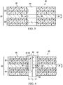
- a structure 21 contains a composite and metal stack 22 with a fastened joint 20.
- the stack 22, sometimes also referred to herein as a composite and metal stack 22, may comprise a single metal layer 24 sandwiched between two composite layers 26, 28, however the stack 22 may comprise any number or combination of composite layers 26, 28 and metal layers 24, including, in its simplest form, a single metal layer 24 and a single composite layer 26.
- the layers 24, 26, 28 in the illustrated joint 20 are fastened together by one or more fasteners 30 that pass through a corresponding hole 40 through layers 24, 26, 28.
- the fastener 30 comprises a bolt having a shank 32, a head 34 and a retainer such as a nut 36, however the fastener 30 may be any of various other fastener forms that are suitable for the application, such as for example and without limitation, a countersunk rivet.
- the hole 40 is cold worked in order to impart residual compressive stresses within a region 38 ( Figure 2 ) of the metal layer 24 surrounding the hole 40. These residual stresses provide the metal layer 24 with resistance to fatigue, and tend to arrest in any small cracks that may form over time in the metal layer 24 around the hole 40.
- the cold working method may be performed entirely from one side 45 of the stack 22, after the stack 22 has been assembled.
- the disclosed cold working method is carried out by applying a force only to the metal layer 24, while substantially avoiding any direct application of force to the composite layers 26, 28 which might deform or have other undesirable effects on the composite layers 26, 28.
- an expandable tool which may comprise, without limitation, a split sleeve 42, is inserted into the hole 40, from one side 45 of the stack 22.
- the split sleeve 42 includes a generally cylindrical wall 52 provided with a longitudinal slit 50 therein, and a circumferential shoulder 44 that seats the split sleeve 42 on the surface 46 surrounding the hole 40.
- the split sleeve 42 is hollow and has an outside diameter D 2 that is normally nominally less than the inside diameter D 1 of the hole 40.
- the split sleeve 42 may be formed from any suitable material that is substantially rigid and incompressible, but which is yieldable to allow the split sleeve 42 to expand. As will be discussed below, cold working of the region 38 metal layer 24 surrounding the hole 40 is achieved by creating an interference between the split sleeve 42 and only the metal layer 24.
- the desired interference between the split sleeve 42 and the metal layer 24 may be achieved by interposing material such as a band-shaped spacer member 48 between the split sleeve 42 and the metal layer 24.
- the spacer member 48 may extend around substantially the entire circumference of the split sleeve 42.
- the spacer member 48 may have a height H that is substantially equal to the thickness t of the metal layer 24.
- the spacer member 48 has a thickness T that will depend on the application, but which is sufficient to maintain a gap G between the outside diameter D 2 of the split sleeve 42 and the composite layers 26, 28 when the split sleeve 42 has been expanded.
- the spacer member 48 is formed on or may be attached to the outside diameter D 2 of the split sleeve 42, however as will be discussed below, other techniques may be used to create the desired gap G between the split sleeve 42 and the composite layers 26, 28.
- a mandrel 56 is slidably received within the split sleeve 42 and passes through a head 60 having an annular lip 62 that is seated on the surface of the stack 22.
- a suitable puller 63 on the head 60 is coupled with the mandrel 56.
- the puller 63 may comprise any suitable device such as a pneumatic cylinder or the like, which pulls 58 the mandrel 56 upwardly through the split sleeve 42.
- the mandrel 56 may be pushed, rather then pulled through the split sleeve 42.
- the mandrel 56 includes an enlarged head portion 56a having an outside diameter D 3 that is greater than the inside diameter of the split sleeve 42.
- the head portion 56a forces the split sleeve 42 to expand 68 ( Figure 6 ) radially.
- the radial expansion of the split sleeve 42 forces the spacer member 48 into contact with the metal layer 24.
- the spacer member 48 transmits and applies an outwardly directed radial force F on the metal layer 24 around the hole 40.
- the radial force F causes the material in the region 38 of the metal layer 24 to yield and be placed in tension.
- the split sleeve 42 is removed from the hole 40 the metal material in region 38 shifts from tension into compression.
- the combination of the split sleeve 42 and internal mandrel 56 is merely illustrative of a wide range of tools that may be used to practice the disclosed method.
- the desired interference with only the metal layer 24 may be achieved using an expandable mandrel (not shown), and a spacer member 48 placed between the metal layer 24 and the expandable mandrel.
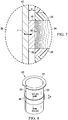
- Figures 8 and 8A illustrate one form of the split sleeve 42, similar to that shown in Figures 4-7 discussed above.
- a band-like spacer member 48 having a height H and a thickness t extends around the circumference of the split sleeve 42.
- the spacer member 48 may comprise a suitable incompressible material that may be formed on or attached to the wall 52 using any of various techniques.
- the spacer member 48 may be formed directly on the wall 52 by electroplating, flame spraying, laser sintering or micro-welding material onto the wall 52.
- a spacer member 48a may be formed integral with the split sleeve 42 by removing material from the split sleeve 42 using etching, machining or other material removal processes.
- the desired interference between the split sleeve 42 and the material layer 24 may be achieved using a spacer member 48b comprising a bushing 54 may be slid over the split sleeve 42 and fixed in place at a desired longitudinal position on the wall 52, aligned with the metal layer 24.
- Figure 10 is in accordance with an embodiment of a method as claimed. This illustrates still another technique for achieving the desired interference for contacting and cold working only the metal layer 24.
- a spacer member 48c comprises a layer of material having a thickness t that is formed directly on the area of the metal layer 24 that surrounds the hole 40.
- the material forming the spacer member 48c may be applied to the metal layer 24 using electroplating, micro-welding, flame spraying, laser sintering or other suitable additive processes.
- the spacer member 48c may be removed after cold-working the metal layer 24, by reaming the hole 40 to the final desired hole diameter, or by other suitable material removal techniques.
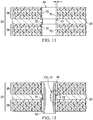
- Figures 11, 12 and 13 illustrate still another example useful for understanding the presently claimed invention of a method of cold working only the metal layer 24, while substantially avoiding contact with the composite layers 26, 28.
- a thickness t of material 70 is removed from each of the composite layers 26, 28 surrounding the hole 40.
- the material 70 may be removed using any suitable material removal technique, such as by machining.
- a hole 40 may be formed in the metal layer 24 that is smaller in diameter than the final diameter of the finished hole 40.
- the composite layers 26, 28 are recessed relative to the metal layer 24 within the hole 40.
- the diameter of the hole 40 within the metal layer 24 is less than the diameter of the hole 40 in either of the composite layers 26, 28.
- the inner edges 72 of the metal layer 24 project into the hole 40 beyond the composite layers 26, 28.
- Figures 12 and 13 show the split sleeve 42 having been installed in the hole 40, but before it has been expanded by an internal mandrel (not shown). As best seen in Figure 13 , a slight amount of clearance 65 is present between the split sleeve wall 52 and the metal layer 24 to accommodate insertion of the split sleeve 42 into the hole 40. Referring to Figure 14 , expansion of the split sleeve 42 causes the split sleeve wall 52 to engage projecting inner edges 72 of the metal layer 24 and apply a force F the metal layer 24.
- edges of the composite layers 26, 28 are recessed relative to the projecting inner edges 72 of the metal layer, a gap G is present between the composite layers 26, 28 and the split sleeve 42 when the latter is fully expanded, consequently the split sleeve 42 cold works only the metal layer 24.
- the projecting inner edges 72 may be removed after cold-working the metal layer 24, by reaming the hole 40 to the final desired hole diameter, or by other suitable material removal techniques.
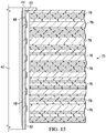
- the disclosed method and device may be employed to cold work a hole in a stack comprising any number and combination of metal and composite layers.
- the method may be employed to cold work a hole 40 in a stack 75 comprising a plurality of metal layers 76 interspersed between composite layers 78.
- a plurality of spacer members 48 are interposed between the metal layers 76 and an expandable split sleeve 42.
- the spacer members 48 are formed on the split sleeve 42 but as previously discussed, other techniques may be used to form interferences between the split sleeve 42 and only the metal layers 76.
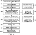
- Figure 16 illustrates the steps of a method of cold working a hole 40 in a composite and metal stack 22.
- composite and metal layers are arranged in a stack 22, and at 82, a hole 40 is formed in the stack 22 using any suitable technique, such as, for example and without limitation, drilling.
- a tool such as the split sleeve 42 previously described, is inserted into the hole 40.
- an interference is formed between the tool and only the metal layers, such that the composite layers are isolated and spaced from the tool. The interference may be achieved using any of several techniques shown at steps 88, 90 and 92.
- material may be added to the tool at locations that are aligned with the metal layers in the stack.
- metal may be added to the metal layer 24 surrounding the hole 40 in order to decrease the inner diameter of the hole 40 at the metal layer 24. Adding of the metal in either of steps 89 or 90 may be performed by any of a variety of techniques, such as those previously discussed as well as other additive manufacturing processes.
- the composite layers may be recessed by removing material from areas of the composite layers, immediately, surrounding the hole 40, thereby recessing the composite layers relative to the metal layers.
- the tool is expanded to apply a radial compression force only to the metal layers. During this step, the tool does not contact or apply force to the composite layers. As a result of this radial compression force, the metal layers are cold worked around the hole 40.
- the tool may be contracted, and then removed from the hole at step 98.
- the holes 40 may be reamed to a final desired diameter, as needed.
- Embodiments of the disclosure may find use in a variety of potential applications, particularly in the transportation industry, including for example, aerospace, marine, automotive applications and other application where fastened joints between composite and metal layers may be used.
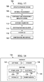
- embodiments of the disclosure may be used in the context of an aircraft manufacturing and service method 102 as shown in Figure 17 and an aircraft 104 as shown in Figure 18 .
- Aircraft applications of the disclosed embodiments may include, for example, without limitation, cold working holes in composite and metal stacks, such as between a metal shear tie and a composite skin, or between metal splices and composite frame sections which form part of the airframe 122.
- exemplary method 102 may include specification and design 106 of the aircraft 104 and material procurement 108. During production, component and subassembly manufacturing 110 and system integration 112 of the aircraft 104 takes place. Thereafter, the aircraft 104 may go through certification and delivery 114 in order to be placed in service 118. While in service by a customer, the aircraft 104 is scheduled for routine maintenance and service 120, which may also include modification, reconfiguration, refurbishment, and so on.
- a system integrator may include without limitation any number of aircraft manufacturers and major-system subcontractors; a third party may include without limitation any number of vendors, subcontractors, and suppliers; and an operator may be an airline, leasing company, military entity, service organization, and so on.
- the aircraft 104 produced by exemplary method 102 may include an airframe 122 with a plurality of systems 124 and an interior 126.
- high-level systems 124 include one or more of a propulsion system 128, an electrical system 130, a hydraulic system 132 and an environmental system 134. Any number of other systems may be included.
- an aerospace example is shown, the principles of the disclosure may be applied to other industries, such as the marine and automotive industries.
- Systems and methods embodied herein may be employed during any one or more of the stages of the production and service method 102.
- components or subassemblies corresponding to production process 110 may be fabricated or manufactured in a manner similar to components or subassemblies produced while the aircraft 104 is in service 118.
- one or more apparatus embodiments, method embodiments, or a combination thereof may be utilized during the production stages 110 and 112, for example, by substantially expediting assembly of or reducing the cost of an aircraft 104.
- apparatus embodiments, method embodiments, or a combination thereof may be utilized while the aircraft 104 is in service, for example and without limitation, to maintenance and service 120.
Landscapes
- Engineering & Computer Science (AREA)
- Mechanical Engineering (AREA)
- Chemical & Material Sciences (AREA)
- General Engineering & Computer Science (AREA)
- Organic Chemistry (AREA)
- Crystallography & Structural Chemistry (AREA)
- Materials Engineering (AREA)
- Metallurgy (AREA)
- Forests & Forestry (AREA)
- Life Sciences & Earth Sciences (AREA)
- Pressure Welding/Diffusion-Bonding (AREA)
- Forging (AREA)
- Laminated Bodies (AREA)
- Shafts, Cranks, Connecting Bars, And Related Bearings (AREA)
- Insertion Pins And Rivets (AREA)
- Connection Of Plates (AREA)
Claims (5)
- Verfahren zum Kaltverformen eines Lochs durch einen Stapel (22) von wenigstens einer Metallschicht (24) und wenigstens einer Verbundschicht (26, 28), das aufweist:Platzieren einer Hülse (42) in dem Loch (40);Herstellen einer Interferenz lediglich zwischen der Hülse (42) und der Metallschicht (24), wobei das Herstellen der Interferenz das Einfügen von Material zwischen die Hülse und die Metallschicht (24) aufweist, und wobei das Einfügen des Materials zwischen die Hülse und die Metallschicht das Aufbringen des Materials auf die Metallschicht (24), die das Loch (40) umgibt, aufweist; undVerwenden der Hülse (42), um eine nach außen gerichtete Radialkraft lediglich auf die Metallschicht (24) aufzubringen durch Erweitern der Hülse durch Ziehen eines Dorns (56) durch die Hülse (42) unter Beibehaltung eines Abstands zwischen der Hülse (42) und der Verbundschicht (26, 28) .
- Verfahren nach Anspruch 1, wobei das Einfügen des Materials das Platzieren einer Buchse (54) zwischen der Hülse und lediglich der Metallschicht (24) aufweist.
- Verfahren nach einem der vorhergehenden Ansprüche, wobei die Hülse (42) eine Splitthülse ist.
- Verfahren nach Anspruch 1, wobei das Aufbringen des Materials auf die Metallschicht (24) durch eines durchgeführt wird von Galvanisieren und Mikroschweißen.
- Verfahren nach Anspruch 1, wobei das Verfahren ein Verfahren zum Kaltverformen eines Lochs durch einen Stapel (75) von Verbund- (78) und Metallschichten (76) ist, das aufweist:Einführen einer Splitthülse (42) in das Loch (40);Einfügen von Material zwischen die Splitthülse (42) und jede der Metallschichten (76), wobei das Einfügen des Materials das Reduzieren des Innendurchmessers des Lochs (40) an jeder der Metallschichten durch Hinzufügen von Material zu den Metallschichten (76), die das Loch (40) umgeben, aufweist;Erweitern der Splitthülse (42), so dass sie lediglich mit den Metallschichten (76) in Kontakt kommt, unter Beibehaltung eines Abstands zwischen den Verbundschichten (78) und der Splitthülse (42); undAufbringen einer Kompressionskraft lediglich auf die Metallschichten (76) durch die Splitthülse (42).
Applications Claiming Priority (1)
| Application Number | Priority Date | Filing Date | Title |
|---|---|---|---|
| US14/062,507 US9180509B2 (en) | 2013-10-24 | 2013-10-24 | Cold working holes in a composite and metal stack |
Publications (2)
| Publication Number | Publication Date |
|---|---|
| EP2865481A1 EP2865481A1 (de) | 2015-04-29 |
| EP2865481B1 true EP2865481B1 (de) | 2020-12-02 |
Family
ID=51870816
Family Applications (1)
| Application Number | Title | Priority Date | Filing Date |
|---|---|---|---|
| EP14190095.1A Active EP2865481B1 (de) | 2013-10-24 | 2014-10-23 | Kaltverformen von Löchern in einem Verbundwerkstoff- und Metallstapel |
Country Status (5)
| Country | Link |
|---|---|
| US (1) | US9180509B2 (de) |
| EP (1) | EP2865481B1 (de) |
| JP (1) | JP6470940B2 (de) |
| CN (2) | CN104552440A (de) |
| CA (1) | CA2862176C (de) |
Families Citing this family (6)
| Publication number | Priority date | Publication date | Assignee | Title |
|---|---|---|---|---|
| FR3043348B1 (fr) * | 2015-11-09 | 2018-03-02 | Airbus Operations | Bague d'expansion comprenant au moins deux portions cylindriques avec des proprietes mecaniques differentes, procede de fabrication d'une telle bague d'expansion et procede d'expansion a froid utilisant ladite bague d'expansion |
| FR3043349B1 (fr) * | 2015-11-09 | 2017-10-27 | Airbus Operations Sas | Bague d'expansion comprenant au moins deux bagues exterieures et procede d'expansion a froid utilisant ladite bague d'expansion |
| US11407034B2 (en) | 2017-07-06 | 2022-08-09 | OmniTek Technology Ltda. | Selective laser melting system and method of using same |
| US11760043B2 (en) * | 2017-09-29 | 2023-09-19 | Honda Motor Co., Ltd. | High strength mechanical fastening inclusions for fiber reinforced polymer structures |
| DK3533998T3 (da) * | 2018-03-01 | 2021-07-05 | Siemens Gamesa Renewable Energy As | Fremgangsmåde til korrosionsbeskyttelse i en vindmølle og vindmølle |
| CN114313300B (zh) * | 2022-02-22 | 2022-07-15 | 成都飞机工业(集团)有限责任公司 | 一种预测并提高飞机部件机表连接件安装合格率的方法 |
Family Cites Families (24)
| Publication number | Priority date | Publication date | Assignee | Title |
|---|---|---|---|---|
| US3953906A (en) * | 1968-10-03 | 1976-05-04 | Brown Clarence K | Fastener assembly |
| US3566662A (en) | 1969-04-28 | 1971-03-02 | Boeing Co | Coldworking method and apparatus |
| US3892121A (en) | 1973-09-12 | 1975-07-01 | Boeing Co | Apparatus for cold-working holes |
| US4187708A (en) | 1977-04-11 | 1980-02-12 | Industrial Wire & Metal Forming, Inc. | Pulling apparatus and method |
| US4230016A (en) * | 1978-07-31 | 1980-10-28 | The Boeing Company | Fatigue resistant fastener and method of manufacturing joints therewith |
| US4244661A (en) * | 1979-07-23 | 1981-01-13 | Mcdonnell Douglas Corporation | Fastener means and joint for laminates |
| US4471643A (en) | 1982-02-10 | 1984-09-18 | Fatigue Technology, Inc. | Method and apparatus for prestressing fastener holes |
| US4715203A (en) | 1985-11-14 | 1987-12-29 | The Boeing Company | Cold-working tool |
| US4763399A (en) | 1986-03-14 | 1988-08-16 | The Boeing Company | Method of bolt hole strengthening in a fibrous composite laminate |
| FR2599791B1 (fr) * | 1986-06-04 | 1988-10-28 | Framatome Sa | Procede de fixation resistante et etanche d'un element cylindrique creux a l'interieur d'un tube et element cylindrique pour la mise en oeuvre de ce procede |
| US5129253A (en) * | 1990-01-26 | 1992-07-14 | Bell Helicopter Textron Inc. | Antifretting coating for a bushing in a coldworked joint |
| US5127254A (en) | 1991-07-10 | 1992-07-07 | Fatigue Technology, Inc. | Method and apparatus for split sleeve cold expansion of openings in structural members |
| US5341559A (en) * | 1993-04-13 | 1994-08-30 | Fatigue Technology, Inc. | Method and apparatus for securing a tubular bushing in a circular opening |
| US5437310A (en) * | 1994-08-05 | 1995-08-01 | Expando Seal Tools, Inc. | Plug assembly |
| US6691789B2 (en) * | 2001-09-10 | 2004-02-17 | Weatherford/Lamb, Inc. | Expandable hanger and packer |
| US7024908B2 (en) | 2003-07-10 | 2006-04-11 | Fatigue Technology, Inc. | Fatigue enhancement of material surrounding openings in workpieces |
| US7152487B2 (en) * | 2004-10-07 | 2006-12-26 | The Boeing Company | Nondestructive verification of minimum tensile elongation of manufactured parts |
| WO2007139953A2 (en) | 2006-05-26 | 2007-12-06 | Fatigue Technology, Inc. | Elongated member/radially expandable member assembly and methods of assembling the same |
| EP2314889B1 (de) * | 2006-09-20 | 2013-04-03 | Woodwelding AG | Verankerung in einem Baumaterial |
| FR2915913B1 (fr) | 2007-05-09 | 2010-02-26 | Airbus France | Procede d'assemblage entre une piece en materiau metallique et une piece en materiau composite au moyen d'une fixation. |
| DE102007055378B4 (de) | 2007-11-19 | 2017-06-29 | Airbus Defence and Space GmbH | Verfahren und Vorrichtung zur Randschichtverfestigung von Bohrungen und Bohrungsanordnung mit randschichtverfestigter Bohrung |
| FR2929352B1 (fr) * | 2008-03-28 | 2010-04-09 | Airbus France | Procede d'assemblage entre une piece en materiau metallique et une piece en materiau composite |
| FR2933896B1 (fr) | 2008-07-16 | 2010-09-24 | Sas Capaero | Procede de montage d'une piece metallique dans une piece en materiau composite |
| US8783735B2 (en) * | 2011-10-24 | 2014-07-22 | The Boeing Company | Conductance on hydraulic fittings using a soft metal interlayer |
-
2013
- 2013-10-24 US US14/062,507 patent/US9180509B2/en active Active
-
2014
- 2014-09-05 CA CA2862176A patent/CA2862176C/en active Active
- 2014-09-25 CN CN201410495340.6A patent/CN104552440A/zh active Pending
- 2014-09-25 CN CN202011318602.3A patent/CN112475365A/zh active Pending
- 2014-10-20 JP JP2014213297A patent/JP6470940B2/ja active Active
- 2014-10-23 EP EP14190095.1A patent/EP2865481B1/de active Active
Non-Patent Citations (1)
| Title |
|---|
| None * |
Also Published As
| Publication number | Publication date |
|---|---|
| CN112475365A (zh) | 2021-03-12 |
| US9180509B2 (en) | 2015-11-10 |
| CA2862176A1 (en) | 2015-04-24 |
| JP6470940B2 (ja) | 2019-02-13 |
| CN104552440A (zh) | 2015-04-29 |
| JP2015096278A (ja) | 2015-05-21 |
| EP2865481A1 (de) | 2015-04-29 |
| US20150114071A1 (en) | 2015-04-30 |
| CA2862176C (en) | 2018-01-16 |
Similar Documents
| Publication | Publication Date | Title |
|---|---|---|
| EP2865481B1 (de) | Kaltverformen von Löchern in einem Verbundwerkstoff- und Metallstapel | |
| EP1166951B1 (de) | Montageverfahren für Buschen mit Doppelflansch | |
| CA2236042C (en) | Mechanical repair for a honeycomb panel | |
| JP3390872B2 (ja) | 冷間加工した継手内のブシュ用のフレッチング防止被覆剤 | |
| US3835525A (en) | Method of fabricating a joint | |
| US20070110541A1 (en) | Radially displaceable bushing for retaining a member relative to a structural workpiece | |
| US20070289351A1 (en) | Wave relieving geometric features in structural members that are radially expandable into workpieces | |
| US20130239399A1 (en) | Expandable fastener assembly with deformed collar | |
| US10232428B2 (en) | Blind track bolt with higher clamp-up strength | |
| US20110000064A1 (en) | Method and apparatus for removing blind fasteners | |
| GB2548245B (en) | One-sided fastener assembly and methods and systems for installing the same | |
| US9296031B2 (en) | Net-shaped duct forming apparatus and method | |
| EP4227544A1 (de) | Strukturelle blindhülsen und zugehörige systeme und verfahren zum klemmen einer ersten struktur in bezug auf eine zweite struktur zur herstellung einer klemmstruktur | |
| US20250135618A1 (en) | Grommet Installation Tool | |
| EP4148287B1 (de) | Blindniete und zugehörige verfahren zum installieren von blindnieten | |
| CN111792019B (zh) | 机械紧固系统及相关结构组件和方法 | |
| US9364880B1 (en) | Systems and methods to cold work metal/composite structures |
Legal Events
| Date | Code | Title | Description |
|---|---|---|---|
| PUAI | Public reference made under article 153(3) epc to a published international application that has entered the european phase |
Free format text: ORIGINAL CODE: 0009012 |
|
| 17P | Request for examination filed |
Effective date: 20141023 |
|
| AK | Designated contracting states |
Kind code of ref document: A1 Designated state(s): AL AT BE BG CH CY CZ DE DK EE ES FI FR GB GR HR HU IE IS IT LI LT LU LV MC MK MT NL NO PL PT RO RS SE SI SK SM TR |
|
| AX | Request for extension of the european patent |
Extension state: BA ME |
|
| STAA | Information on the status of an ep patent application or granted ep patent |
Free format text: STATUS: EXAMINATION IS IN PROGRESS |
|
| 17Q | First examination report despatched |
Effective date: 20180406 |
|
| GRAP | Despatch of communication of intention to grant a patent |
Free format text: ORIGINAL CODE: EPIDOSNIGR1 |
|
| STAA | Information on the status of an ep patent application or granted ep patent |
Free format text: STATUS: GRANT OF PATENT IS INTENDED |
|
| RIC1 | Information provided on ipc code assigned before grant |
Ipc: C21D 7/12 20060101ALI20190429BHEP Ipc: B23P 9/02 20060101AFI20190429BHEP Ipc: F16B 19/08 20060101ALN20190429BHEP |
|
| RIC1 | Information provided on ipc code assigned before grant |
Ipc: C21D 7/12 20060101ALI20190515BHEP Ipc: F16B 19/08 20060101ALN20190515BHEP Ipc: B23P 9/02 20060101AFI20190515BHEP |
|
| INTG | Intention to grant announced |
Effective date: 20190531 |
|
| RIC1 | Information provided on ipc code assigned before grant |
Ipc: C21D 7/12 20060101ALI20190517BHEP Ipc: F16B 19/08 20060101ALN20190517BHEP Ipc: B23P 9/02 20060101AFI20190517BHEP |
|
| RIN1 | Information on inventor provided before grant (corrected) |
Inventor name: ALLEN, NATHAN ANDREW Inventor name: TON-THAT, JULIE A. Inventor name: LAWRENCE, ANTHONY B. Inventor name: JONES, MICHAEL D. |
|
| GRAJ | Information related to disapproval of communication of intention to grant by the applicant or resumption of examination proceedings by the epo deleted |
Free format text: ORIGINAL CODE: EPIDOSDIGR1 |
|
| STAA | Information on the status of an ep patent application or granted ep patent |
Free format text: STATUS: EXAMINATION IS IN PROGRESS |
|
| INTC | Intention to grant announced (deleted) | ||
| RIC1 | Information provided on ipc code assigned before grant |
Ipc: F16B 19/08 20060101ALN20200306BHEP Ipc: B23P 9/02 20060101AFI20200306BHEP Ipc: C21D 7/12 20060101ALI20200306BHEP |
|
| GRAP | Despatch of communication of intention to grant a patent |
Free format text: ORIGINAL CODE: EPIDOSNIGR1 |
|
| STAA | Information on the status of an ep patent application or granted ep patent |
Free format text: STATUS: GRANT OF PATENT IS INTENDED |
|
| RIC1 | Information provided on ipc code assigned before grant |
Ipc: B23P 9/02 20060101AFI20200408BHEP Ipc: F16B 19/08 20060101ALN20200408BHEP Ipc: C21D 7/12 20060101ALI20200408BHEP |
|
| INTG | Intention to grant announced |
Effective date: 20200504 |
|
| GRAJ | Information related to disapproval of communication of intention to grant by the applicant or resumption of examination proceedings by the epo deleted |
Free format text: ORIGINAL CODE: EPIDOSDIGR1 |
|
| GRAP | Despatch of communication of intention to grant a patent |
Free format text: ORIGINAL CODE: EPIDOSNIGR1 |
|
| GRAJ | Information related to disapproval of communication of intention to grant by the applicant or resumption of examination proceedings by the epo deleted |
Free format text: ORIGINAL CODE: EPIDOSDIGR1 |
|
| STAA | Information on the status of an ep patent application or granted ep patent |
Free format text: STATUS: EXAMINATION IS IN PROGRESS |
|
| INTG | Intention to grant announced |
Effective date: 20200504 |
|
| INTC | Intention to grant announced (deleted) | ||
| GRAR | Information related to intention to grant a patent recorded |
Free format text: ORIGINAL CODE: EPIDOSNIGR71 |
|
| GRAS | Grant fee paid |
Free format text: ORIGINAL CODE: EPIDOSNIGR3 |
|
| STAA | Information on the status of an ep patent application or granted ep patent |
Free format text: STATUS: GRANT OF PATENT IS INTENDED |
|
| RIC1 | Information provided on ipc code assigned before grant |
Ipc: C21D 7/12 20060101ALI20200915BHEP Ipc: B23P 9/02 20060101AFI20200915BHEP Ipc: F16B 19/08 20060101ALN20200915BHEP |
|
| GRAA | (expected) grant |
Free format text: ORIGINAL CODE: 0009210 |
|
| STAA | Information on the status of an ep patent application or granted ep patent |
Free format text: STATUS: THE PATENT HAS BEEN GRANTED |
|
| INTG | Intention to grant announced |
Effective date: 20201016 |
|
| AK | Designated contracting states |
Kind code of ref document: B1 Designated state(s): AL AT BE BG CH CY CZ DE DK EE ES FI FR GB GR HR HU IE IS IT LI LT LU LV MC MK MT NL NO PL PT RO RS SE SI SK SM TR |
|
| REG | Reference to a national code |
Ref country code: GB Ref legal event code: FG4D |
|
| REG | Reference to a national code |
Ref country code: AT Ref legal event code: REF Ref document number: 1340372 Country of ref document: AT Kind code of ref document: T Effective date: 20201215 Ref country code: CH Ref legal event code: EP |
|
| REG | Reference to a national code |
Ref country code: IE Ref legal event code: FG4D |
|
| REG | Reference to a national code |
Ref country code: DE Ref legal event code: R096 Ref document number: 602014072865 Country of ref document: DE |
|
| PG25 | Lapsed in a contracting state [announced via postgrant information from national office to epo] |
Ref country code: NO Free format text: LAPSE BECAUSE OF FAILURE TO SUBMIT A TRANSLATION OF THE DESCRIPTION OR TO PAY THE FEE WITHIN THE PRESCRIBED TIME-LIMIT Effective date: 20210302 Ref country code: FI Free format text: LAPSE BECAUSE OF FAILURE TO SUBMIT A TRANSLATION OF THE DESCRIPTION OR TO PAY THE FEE WITHIN THE PRESCRIBED TIME-LIMIT Effective date: 20201202 Ref country code: RS Free format text: LAPSE BECAUSE OF FAILURE TO SUBMIT A TRANSLATION OF THE DESCRIPTION OR TO PAY THE FEE WITHIN THE PRESCRIBED TIME-LIMIT Effective date: 20201202 Ref country code: GR Free format text: LAPSE BECAUSE OF FAILURE TO SUBMIT A TRANSLATION OF THE DESCRIPTION OR TO PAY THE FEE WITHIN THE PRESCRIBED TIME-LIMIT Effective date: 20210303 |
|
| REG | Reference to a national code |
Ref country code: NL Ref legal event code: MP Effective date: 20201202 |
|
| REG | Reference to a national code |
Ref country code: AT Ref legal event code: MK05 Ref document number: 1340372 Country of ref document: AT Kind code of ref document: T Effective date: 20201202 |
|
| PG25 | Lapsed in a contracting state [announced via postgrant information from national office to epo] |
Ref country code: LV Free format text: LAPSE BECAUSE OF FAILURE TO SUBMIT A TRANSLATION OF THE DESCRIPTION OR TO PAY THE FEE WITHIN THE PRESCRIBED TIME-LIMIT Effective date: 20201202 Ref country code: PL Free format text: LAPSE BECAUSE OF FAILURE TO SUBMIT A TRANSLATION OF THE DESCRIPTION OR TO PAY THE FEE WITHIN THE PRESCRIBED TIME-LIMIT Effective date: 20201202 Ref country code: SE Free format text: LAPSE BECAUSE OF FAILURE TO SUBMIT A TRANSLATION OF THE DESCRIPTION OR TO PAY THE FEE WITHIN THE PRESCRIBED TIME-LIMIT Effective date: 20201202 Ref country code: BG Free format text: LAPSE BECAUSE OF FAILURE TO SUBMIT A TRANSLATION OF THE DESCRIPTION OR TO PAY THE FEE WITHIN THE PRESCRIBED TIME-LIMIT Effective date: 20210302 |
|
| PG25 | Lapsed in a contracting state [announced via postgrant information from national office to epo] |
Ref country code: HR Free format text: LAPSE BECAUSE OF FAILURE TO SUBMIT A TRANSLATION OF THE DESCRIPTION OR TO PAY THE FEE WITHIN THE PRESCRIBED TIME-LIMIT Effective date: 20201202 Ref country code: NL Free format text: LAPSE BECAUSE OF FAILURE TO SUBMIT A TRANSLATION OF THE DESCRIPTION OR TO PAY THE FEE WITHIN THE PRESCRIBED TIME-LIMIT Effective date: 20201202 |
|
| REG | Reference to a national code |
Ref country code: LT Ref legal event code: MG9D |
|
| PG25 | Lapsed in a contracting state [announced via postgrant information from national office to epo] |
Ref country code: PT Free format text: LAPSE BECAUSE OF FAILURE TO SUBMIT A TRANSLATION OF THE DESCRIPTION OR TO PAY THE FEE WITHIN THE PRESCRIBED TIME-LIMIT Effective date: 20210405 Ref country code: SK Free format text: LAPSE BECAUSE OF FAILURE TO SUBMIT A TRANSLATION OF THE DESCRIPTION OR TO PAY THE FEE WITHIN THE PRESCRIBED TIME-LIMIT Effective date: 20201202 Ref country code: RO Free format text: LAPSE BECAUSE OF FAILURE TO SUBMIT A TRANSLATION OF THE DESCRIPTION OR TO PAY THE FEE WITHIN THE PRESCRIBED TIME-LIMIT Effective date: 20201202 Ref country code: LT Free format text: LAPSE BECAUSE OF FAILURE TO SUBMIT A TRANSLATION OF THE DESCRIPTION OR TO PAY THE FEE WITHIN THE PRESCRIBED TIME-LIMIT Effective date: 20201202 Ref country code: CZ Free format text: LAPSE BECAUSE OF FAILURE TO SUBMIT A TRANSLATION OF THE DESCRIPTION OR TO PAY THE FEE WITHIN THE PRESCRIBED TIME-LIMIT Effective date: 20201202 Ref country code: EE Free format text: LAPSE BECAUSE OF FAILURE TO SUBMIT A TRANSLATION OF THE DESCRIPTION OR TO PAY THE FEE WITHIN THE PRESCRIBED TIME-LIMIT Effective date: 20201202 Ref country code: SM Free format text: LAPSE BECAUSE OF FAILURE TO SUBMIT A TRANSLATION OF THE DESCRIPTION OR TO PAY THE FEE WITHIN THE PRESCRIBED TIME-LIMIT Effective date: 20201202 |
|
| PG25 | Lapsed in a contracting state [announced via postgrant information from national office to epo] |
Ref country code: AT Free format text: LAPSE BECAUSE OF FAILURE TO SUBMIT A TRANSLATION OF THE DESCRIPTION OR TO PAY THE FEE WITHIN THE PRESCRIBED TIME-LIMIT Effective date: 20201202 |
|
| REG | Reference to a national code |
Ref country code: DE Ref legal event code: R097 Ref document number: 602014072865 Country of ref document: DE |
|
| PG25 | Lapsed in a contracting state [announced via postgrant information from national office to epo] |
Ref country code: IS Free format text: LAPSE BECAUSE OF FAILURE TO SUBMIT A TRANSLATION OF THE DESCRIPTION OR TO PAY THE FEE WITHIN THE PRESCRIBED TIME-LIMIT Effective date: 20210402 |
|
| PLBE | No opposition filed within time limit |
Free format text: ORIGINAL CODE: 0009261 |
|
| STAA | Information on the status of an ep patent application or granted ep patent |
Free format text: STATUS: NO OPPOSITION FILED WITHIN TIME LIMIT |
|
| PG25 | Lapsed in a contracting state [announced via postgrant information from national office to epo] |
Ref country code: IT Free format text: LAPSE BECAUSE OF FAILURE TO SUBMIT A TRANSLATION OF THE DESCRIPTION OR TO PAY THE FEE WITHIN THE PRESCRIBED TIME-LIMIT Effective date: 20201202 Ref country code: AL Free format text: LAPSE BECAUSE OF FAILURE TO SUBMIT A TRANSLATION OF THE DESCRIPTION OR TO PAY THE FEE WITHIN THE PRESCRIBED TIME-LIMIT Effective date: 20201202 |
|
| 26N | No opposition filed |
Effective date: 20210903 |
|
| PG25 | Lapsed in a contracting state [announced via postgrant information from national office to epo] |
Ref country code: ES Free format text: LAPSE BECAUSE OF FAILURE TO SUBMIT A TRANSLATION OF THE DESCRIPTION OR TO PAY THE FEE WITHIN THE PRESCRIBED TIME-LIMIT Effective date: 20201202 Ref country code: DK Free format text: LAPSE BECAUSE OF FAILURE TO SUBMIT A TRANSLATION OF THE DESCRIPTION OR TO PAY THE FEE WITHIN THE PRESCRIBED TIME-LIMIT Effective date: 20201202 Ref country code: SI Free format text: LAPSE BECAUSE OF FAILURE TO SUBMIT A TRANSLATION OF THE DESCRIPTION OR TO PAY THE FEE WITHIN THE PRESCRIBED TIME-LIMIT Effective date: 20201202 |
|
| REG | Reference to a national code |
Ref country code: CH Ref legal event code: PL |
|
| PG25 | Lapsed in a contracting state [announced via postgrant information from national office to epo] |
Ref country code: IS Free format text: LAPSE BECAUSE OF FAILURE TO SUBMIT A TRANSLATION OF THE DESCRIPTION OR TO PAY THE FEE WITHIN THE PRESCRIBED TIME-LIMIT Effective date: 20210402 |
|
| REG | Reference to a national code |
Ref country code: BE Ref legal event code: MM Effective date: 20211031 |
|
| PG25 | Lapsed in a contracting state [announced via postgrant information from national office to epo] |
Ref country code: MC Free format text: LAPSE BECAUSE OF FAILURE TO SUBMIT A TRANSLATION OF THE DESCRIPTION OR TO PAY THE FEE WITHIN THE PRESCRIBED TIME-LIMIT Effective date: 20201202 |
|
| PG25 | Lapsed in a contracting state [announced via postgrant information from national office to epo] |
Ref country code: LU Free format text: LAPSE BECAUSE OF NON-PAYMENT OF DUE FEES Effective date: 20211023 Ref country code: BE Free format text: LAPSE BECAUSE OF NON-PAYMENT OF DUE FEES Effective date: 20211031 |
|
| PG25 | Lapsed in a contracting state [announced via postgrant information from national office to epo] |
Ref country code: LI Free format text: LAPSE BECAUSE OF NON-PAYMENT OF DUE FEES Effective date: 20211031 Ref country code: CH Free format text: LAPSE BECAUSE OF NON-PAYMENT OF DUE FEES Effective date: 20211031 |
|
| PG25 | Lapsed in a contracting state [announced via postgrant information from national office to epo] |
Ref country code: IE Free format text: LAPSE BECAUSE OF NON-PAYMENT OF DUE FEES Effective date: 20211023 |
|
| PG25 | Lapsed in a contracting state [announced via postgrant information from national office to epo] |
Ref country code: HU Free format text: LAPSE BECAUSE OF FAILURE TO SUBMIT A TRANSLATION OF THE DESCRIPTION OR TO PAY THE FEE WITHIN THE PRESCRIBED TIME-LIMIT; INVALID AB INITIO Effective date: 20141023 |
|
| P01 | Opt-out of the competence of the unified patent court (upc) registered |
Effective date: 20230516 |
|
| PG25 | Lapsed in a contracting state [announced via postgrant information from national office to epo] |
Ref country code: CY Free format text: LAPSE BECAUSE OF FAILURE TO SUBMIT A TRANSLATION OF THE DESCRIPTION OR TO PAY THE FEE WITHIN THE PRESCRIBED TIME-LIMIT Effective date: 20201202 |
|
| PG25 | Lapsed in a contracting state [announced via postgrant information from national office to epo] |
Ref country code: MK Free format text: LAPSE BECAUSE OF FAILURE TO SUBMIT A TRANSLATION OF THE DESCRIPTION OR TO PAY THE FEE WITHIN THE PRESCRIBED TIME-LIMIT Effective date: 20201202 |
|
| PG25 | Lapsed in a contracting state [announced via postgrant information from national office to epo] |
Ref country code: TR Free format text: LAPSE BECAUSE OF FAILURE TO SUBMIT A TRANSLATION OF THE DESCRIPTION OR TO PAY THE FEE WITHIN THE PRESCRIBED TIME-LIMIT Effective date: 20201202 |
|
| PG25 | Lapsed in a contracting state [announced via postgrant information from national office to epo] |
Ref country code: MT Free format text: LAPSE BECAUSE OF FAILURE TO SUBMIT A TRANSLATION OF THE DESCRIPTION OR TO PAY THE FEE WITHIN THE PRESCRIBED TIME-LIMIT Effective date: 20201202 |
|
| PGFP | Annual fee paid to national office [announced via postgrant information from national office to epo] |
Ref country code: DE Payment date: 20241029 Year of fee payment: 11 |
|
| PGFP | Annual fee paid to national office [announced via postgrant information from national office to epo] |
Ref country code: GB Payment date: 20241028 Year of fee payment: 11 |
|
| PGFP | Annual fee paid to national office [announced via postgrant information from national office to epo] |
Ref country code: FR Payment date: 20241025 Year of fee payment: 11 |