EP2865352A1 - Abtastende einspannvorrichtung - Google Patents
Abtastende einspannvorrichtung Download PDFInfo
- Publication number
- EP2865352A1 EP2865352A1 EP13810242.1A EP13810242A EP2865352A1 EP 2865352 A1 EP2865352 A1 EP 2865352A1 EP 13810242 A EP13810242 A EP 13810242A EP 2865352 A1 EP2865352 A1 EP 2865352A1
- Authority
- EP
- European Patent Office
- Prior art keywords
- analog
- scanning jig
- main body
- artificial tooth
- tooth root
- Prior art date
- Legal status (The legal status is an assumption and is not a legal conclusion. Google has not performed a legal analysis and makes no representation as to the accuracy of the status listed.)
- Withdrawn
Links
Images








Classifications
-
- A—HUMAN NECESSITIES
- A61—MEDICAL OR VETERINARY SCIENCE; HYGIENE
- A61C—DENTISTRY; APPARATUS OR METHODS FOR ORAL OR DENTAL HYGIENE
- A61C8/00—Means to be fixed to the jaw-bone for consolidating natural teeth or for fixing dental prostheses thereon; Dental implants; Implanting tools
- A61C8/0001—Impression means for implants, e.g. impression coping
-
- A—HUMAN NECESSITIES
- A61—MEDICAL OR VETERINARY SCIENCE; HYGIENE
- A61C—DENTISTRY; APPARATUS OR METHODS FOR ORAL OR DENTAL HYGIENE
- A61C13/00—Dental prostheses; Making same
- A61C13/225—Fastening prostheses in the mouth
- A61C13/235—Magnetic fastening
-
- A—HUMAN NECESSITIES
- A61—MEDICAL OR VETERINARY SCIENCE; HYGIENE
- A61C—DENTISTRY; APPARATUS OR METHODS FOR ORAL OR DENTAL HYGIENE
- A61C13/00—Dental prostheses; Making same
- A61C13/34—Making or working of models, e.g. preliminary castings, trial dentures; Dowel pins [4]
-
- A—HUMAN NECESSITIES
- A61—MEDICAL OR VETERINARY SCIENCE; HYGIENE
- A61C—DENTISTRY; APPARATUS OR METHODS FOR ORAL OR DENTAL HYGIENE
- A61C9/00—Impression cups, i.e. impression trays; Impression methods
- A61C9/004—Means or methods for taking digitized impressions
- A61C9/0046—Data acquisition means or methods
- A61C9/0053—Optical means or methods, e.g. scanning the teeth by a laser or light beam
Definitions
- the present invention relates to a scanning jig which is a member used in the field of dentistry for specifying a position of an embedded artificial tooth root (may be generally called an implant fixture or an implant body) to obtain a three-dimensional data.
- a so-called dental implant technique has been largely applied as a prosthesis method for a defective tooth.
- the application of implant with the dental implant technique has more advantages compared with a conventional dental prosthesis, since it can make a state closer to that of a natural tooth.
- a treatment with the implant is generally carried out by the following processes. That is: a hole is created to the jawbone at the defective site where the implant is to be applied; an artificial tooth root is embedded thereto; after the embedded artificial tooth root is sufficiently joined to the jawbone, an abutment which is a member for fixating a dental prosthesis is attached to the embedded artificial tooth root; then the dental prosthesis is arranged to the abutment.
- the abutment is designed and produced individually for each patient in conformity with the depth and direction of the embedded artificial tooth root, and a state of the patient's oral cavity.
- the abutment since the abutment has to be produced in conformity with a state of the artificial tooth root actually embedded, it is needed to know how the artificial tooth root is embedded before the abutment is produced.
- information of the posture (depth and direction) of the artificial tooth root being embedded is transferred to an analog model which is a plaster model including an analog (a replica of the artificial tooth root). From the analogue model, the information of the artificial tooth root is obtained, whereby the abutment is produced.
- the abutment is produced by means of an automatic cutting processing with three-dimensional shape data, and even an abutment having a complicated shape can be produced with a good accuracy. Therefore, in order to obtain the three-dimensional shape data for processing, it is needed to obtain a three-dimensional shape data including shapes of required parts in a person's oral cavity, an outer shape of the analog model, and postural information such as the depth and direction of the artificial tooth root.
- the postural information (depth and direction) of the artificial tooth root is transferred to the analog and the analog is embedded inside the analog model, it is not possible to obtain the postural information of the artificial tooth root as a three-dimensional shape data as it is.
- a scanning jig attached to the embedded analog in a manner to extend the analog, thereby being arranged such that one end side thereof projects from the analog model is used. That is, the scanning jig is attached coaxially to the analog, and an end portion of the scanning jig where the analog is not connected is exposed in a manner to project from the analog model. Therefore, it is possible to obtain the direction and positional information of the analog.
- the three-dimensional shape data of the scanning jig is replaced with a three-dimensional shape data of the scanning jig which is prepared in advance.
- scanning jig is not necessarily widely used in the technical field of the present invention. However, since there is no unified name in the technical field, for a member which corresponds to the scanning jig having functions described above, the member is herein described as the "scanning jig".
- Patent Document 1 U.S. patent application Ser. No. 2009/0123887
- the replacement accuracy in the longitudinal direction and the replacement accuracy in the orientation of the rotational direction as above are important, since they affect the fitting accuracy of the abutment and the artificial tooth root.
- an object of the present invention is to provide a scanning jig capable of improving replacement accuracy of three-dimensional shape data.
- the present invention is a scanning jig (10) for attaching to an analog (20) embedded in a model, or to an artificial tooth root (30) embedded in an oral cavity, the scanning jig including: a main body (11) formed in a bottomed cylindrical shape provided with a bottom to one end portion; a fixation member (12) of which one end side is inserted inside the cylindrical shape of the main body and the other end side is fixated to the analog or the artificial tooth root; and a magnet (13) arranged inside the cylindrical shape of the main body, wherein: the main body is not provided with a hole or a groove on an end surface on a bottom side of the bottomed cylindrical shape; and the end surface is provided with an inclined surface.
- the main body (11) may be, with a posture of being attached to the analog (20) or the artificial tooth root (30), configured such that only one end surface on a side where the bottom is not formed has contact with the analog or the artificial tooth root.
- the present invention after obtaining a three-dimensional shape data with the scanning jig attached to the analog of the analog model, or after obtaining a three-dimensional shape data with the scanning jig attached to the artificial tooth root embedded in an oral cavity, it is possible to improve the replacement accuracy of the scanning jig especially in the longitudinal direction (axial direction), in replacing the portion of the scanning jig in the three-dimensional shape data with a three-dimensional shape data of the scanning jig obtained in advance.
- Fig. 1 is a perspective view of an external appearance of a scanning jig 10 according to one embodiment.
- Fig. 2 is a cross-sectional view taken along a longitudinal direction (axial direction) of the scanning jig including a line shown by II-II in Fig. 1 .
- the scanning jig 10 includes a main body 11, a fixation member 12, and a magnet 13.
- the main body 11 is a member formed in a bottomed cylindrical shape provided with a bottom only to one end side. As shown in Fig. 2 , a hollow part 11a is formed inside the main body 11.
- the hollow part 11a has an enough size and shape to insert a fixation member 12, as described below.
- the main body 11 there is no hole or a groove on an end surface 11b which is an end surface of the bottomed cylindrical shape and on a side configuring one end surface of the scanning jig 10.
- the main body 11 is configured such that the end surface 11b has a large dimension. Further, an inclined surface 11c is formed to a part of the end surface 11b.
- the main body 11 is formed so as to have different outer diameters between on one end side and on the other end side in the longitudinal direction of the cylindrical shape at a circumference side.
- a portion where the outer diameters are changed is a taper 11g.
- the portion where the outer diameters are changed is formed as a taper.
- the present invention is not limited to this, and may be a level gap in which the outer diameters are rapidly changed.
- an end surface 11e which functions as a position determination means in an axial direction is formed to a side opposite from the end surface 11b where the bottom exists.
- the side where the end surface 11e is formed includes an opening communicating to the hollow part 11a.
- a protrusion 11f is provided to a part of the end surface 11e, as a position determination means in rotational direction.
- a fitting part 11d formed in a cylindrical shape is arranged in a manner to extend in a direction extending the main body 11 to the longitudinal direction (axial direction).
- the fitting part 11d functions as a position determination means in radial direction of the main body 11 as well, and it is formed so as to be inserted to the analog embedded to the analog model, or to a fitted part (see a fitted part 20d in Fig. 6 for example) of the artificial tooth root embedded in an oral cavity, as described below.
- the fitting part 11d is provided to a hollow part 11a side of the end surface 11e.
- the main body 11 is formed of a metal or a resin being a material having a high processing accuracy and a high accuracy sustention effect. Also, it is preferable that the material does not cause malfunctions to a measuring device. For example, in a case where a measurement is carried out by means of laser light, resins are preferable, and among them, an engineering plastic is most preferable in view of having balance with processing with a high accuracy.
- the fixation member 12 is a fixation member arranged inside the hollow part 11a of the main body 11, and in this embodiment, configured by a screw.
- the fixation member 12 of this embodiment is arranged such that a screw part 12a provided to one end is projected from the main body 11, and the screw part 12a is threaded with a hollow part 20a (see Fig. 6 ) of the analog or a hollow part 20a (see Fig. 12 ) of the artificial tooth root.
- the other end of the fixation member 12 is provided with a screw head.
- fixation member 12 is made of a material to be attracted by a magnet.
- the magnet 13 is a magnet arranged to a side closest to the bottom of the bottomed cylindrical shape in the hollow part 11a of the main body 11.
- the magnet 13 is preferably made of a material difficult to be demagnetized, from a viewpoint that the fixation member 12 is repeatedly used.
- a permanent magnet is easy to use, and a small magnet but having a strong magnetic flux as much as possible is desired.
- rare earth magnets such as SmCo based magnet and NdFe based magnet are preferable.
- the shape of the magnet is normally in a cylindrical shape or a columnar shape, depending on conditions to use.
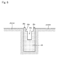
- the scanning jig 10 As described above, it is possible to attach the scanning jig 10 to the analog in the analog model or the artificial tooth root in the oral cavity, as described below. Then, the scanning jig 10 is arranged in a manner to project from the analog model or a gum in a direction extending the analog embedded in the analog model or the artificial tooth root in the oral cavity. By measuring the scanning jig at the projected portion, it becomes possible to obtain the embedded posture of the analog or the artificial tooth root (see Figs. 8 and 12 ).
- the scanning jig 10 it is possible to form a large dimension of the end surface of the scanning jig 10, including the inclined surface 11c, without having a hole or a groove on the end surface 11b. As described later, this makes it possible to improve the replacement accuracy in the longitudinal direction (axial direction) of the scanning jig 10 in replacing an obtained shape measurement data from a three-dimensional measurement of the scanning jig attached to the analog model or in the oral cavity, with a three-dimensional data of the scanning jig prepared in advance.
- the end surface of the scanning jig cannot have a large dimension, since it is formed in an annular shape with a hole or there is a groove of a screw head for example.
- the scanning jig 10 can have a large dimension at the end surface 11b including the inclined surface 11c as described above, thus it is possible to improve the replacement accuracy of the position in the longitudinal direction.
- other directions than the longitudinal direction of the scanning jig 10 since an outer peripheral surface of the main body 11 has a sufficient dimension, a replacement is carried out with a good accuracy.
- the inclined surface 11c to the end portion 11b, it is possible to show the orientation of the scanning jig 10 in the rotational direction centering the rotation axis of the scanning jig 10 (cylindrical axis of the main body 11). This also makes it possible to improve the replacement accuracy in the rotational direction.
- the configuration of the inclined surface 11c depending on kinds of the artificial tooth root for example, it is also possible to obtain information regarding what kind of artificial tooth root is applied. Therefore, inclining angle, dimension of the inclined surface, and the configuration of the inclined surface are not limited to this embodiment but can be adequately changed.
- each position determination is not affected by the other portions, whereby it is possible to improve the accuracy of position determination.
- the axis direction of the main body 11 only the end surface 11e as the position determination means in axis direction has contact with the analog or the artificial tooth root to determine the position. That is, the end surface of the fitting portion 11d does not have contact with the analog 20 or the artificial tooth root 30, and the main body 11 and the magnet 13 do not have contact with the fixation member 12 in the axial direction (see Figs. 8 and 12 ).
- abutment manufacturing method S1 which is one example of a method for manufacturing an abutment using the scanning jig 10 will be described.
- This method is a manufacturing method of an abutment using an analog model.
- Fig. 3 shows a flow of the abutment manufacturing method S1.
- the abutment manufacturing method S1 includes an analog model producing step S10, a three-dimensional data creating step S20, and an abutment producing step S30. Each step will be described hereinafter.
- the analog model producing step S10 is a step of producing an analog model in which the analog 20 is embedded.
- a known step can be applied to this step.
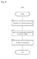
- Fig. 4 shows an example of flow of the analog model producing step S10. That is, the analog model producing step S10 includes an artificial tooth root embedding step S11, an impression obtaining step S12 by means of an impression coping, and an analog model forming step S13.
- the artificial tooth root embedding step S11 is a step of creating a hole to embed an artificial tooth root to the jawbone at the defective site of a tooth, and embedding the artificial tooth root.
- the impression obtaining step S12 by means of an impression coping is a step of obtaining an impression by means of an impression coping, after the embedded artificial tooth root sufficiently joins to the jawbone.
- the impression obtaining by means of an impression coping may be carried out by a known method.
- the analog model forming step S13 is a step of attaching an analog to the impression obtained by the impression obtaining step S12 by means of the impression coping, and to the impression coping in the impression, and based on the impression and the coping, producing a plaster model. That is, an analog model which is a plaster model in which the analog is embedded is formed.
- the three-dimensional data creating step S20 is a step of making a three-dimensional shape data of the abutment to be produced.
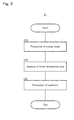
- the three-dimensional data creating step S20 may be carried out as shown in Fig. 5 for example.
- Fig. 5 shows a flow of the three-dimensional data creating step S20. That is, the three-dimensional data creating step S20 includes a scanning jig attachment step S21, a three-dimensional measurement step S22, a data replacement step S23, and an abutment data creating step S24.
- the scanning jig attachment step S21 is a step of attaching the scanning jig 10 described above to the analog model produced in the analog model producing step S10.
- the order and the like of the step are schematically shown by drawings of Figs. 6 to 9 .
- Fig. 6 schematically shows a configuration of the analog 20 embedded in the analog model.
- the analog 20 is also a member formed in a bottomed cylindrical shape provided with a bottom only on one side, and the hollow part 20a is formed thereinside.
- a female screw groove is formed in the hollow part 20a so that the fixation member 12 of the scanning jig 10 can be threaded.
- a surface having an opening communicating to the hollow part 20a becomes an end surface 20b having contact with the end surface 11e which functions as the position determination means in axial direction of the main body 11 of the scanning jig 10. Also, a part of the end surface 20b is provided with a groove 20c in a manner to cut a cylindrical wall part of the analog 20 in the radial direction.
- a fitted part 20d cut off in a manner to be dug down along with the longitudinal direction of the analog 20 is formed.
- the analog 20 is embedded in the plaster configuring an external appearance of the analog model. Therefore the embedded angle and depth of the analog 20 cannot be seen from the external appearance of the analog model.
- the fixation member 12 is attached such that the one end side of the fixation member 12 where the screw part 12a is arranged is threaded. This is carried out by threading the screw part 12a of the fixation member 12 to the female screw groove formed to the hollow part 20a.
- the main body 11 is installed in a manner to put it on the fixation member 12 standing on the analog 20.
- the other end side of the fixation member 12 where the screw head is arranged is inserted to the hollow part 11a of the main body 11.
- Fig. 8 is a schematic view of a situation in which the scanning jig 10 is attached to the analog model as described above.
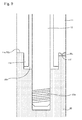
- Fig. 9 is an enlarged view of a portion shown by IX in Fig. 8 .
- the position in the axial direction of the main body 11 is determined only by the end surface 11e as the position determination means in axial direction having contact with the end surface 20b of the analog 20. Therefore, the end surface of the fitting part 11d does not have contact with the analog 20, and the main body 11 and the magnet 13 do not have contact with the fixation member 12 in the axial direction.
- the position of the main body 11 in the rotational direction is determined only by the protrusion 11f as the position determination means in rotational direction entering inside the groove 20c of the analog 20.
- the position of the main body 11 in the radial direction is determined only by the fitting part 11d as the position determination means in radial direction getting inserted to the fitted part 20d of the analog 20.
- each position determination means As described above, only by each position determination means, each of the position determinations in the axial direction, in the rotational direction, and in the radial direction is carried out at the one contacting portion (position determination means) to the analog 20. Therefore each position determination is not affected by the other portions, whereby it is possible to improve accuracy of the position determination.
- the main body 11 can be arranged only by putting it on the fixation member 12, and the main body 11 and the fixation member 12 are arranged stably by the attractive force of the magnet 13 without requiring any fixation by a screw or the like, easy disposition and stable attachment can be realized.
- the magnet 13 and the fixation member 12 do not have a direct contact with each other. However, since they are arranged close to each other, the attractive force works between them.
- the scanning jig 10 is arranged in a manner to project from the analog model in a direction extending the analog 20 embedded inside the analog model, then the analog 20 to which the scanning jig 10 is attached is formed, whereby it becomes possible to obtain the embedded posture of the analog 20.
- the three-dimensional measurement step S22 is a step of measuring three-dimensionally the shape of the analog model to which the scanning jig 10 is attached. This makes it possible to obtain the shapes of the analog model and the scanning jig 10 attached to the analog model as three-dimensional shape data.
- a general three-dimensional measuring apparatus can be used.
- the data replacement step S23 is a step of replacing a corresponding portion of the three-dimensional shape data obtained in the three-dimensional measurement step S22, with a three-dimensional shape data of the artificial tooth root and a three-dimensional shape data of the scanning jig that are prepared in advance. That is, the three-dimensional shape data of the scanning jig prepared in advance is replaced in a manner to apply to the portion where the scanning jig 10 is arranged in the three-dimensional shape data of the analog model. Also, the three-dimensional shape data of the artificial tooth root prepared in advance is applied to the portion of the analog 20 which can be obtained from the scanning jig 10. A known method can be applied for this replacement.
- the end surface 11b including the inclined surface 11c of the scanning jig 10 has a large dimension, and the replacement accuracy in the axial direction (longitudinal direction) of the scanning jig 10 is improved.
- the replacement accuracy of data in the rotational direction is also improved because of the shape of the inclined surface 11c.
- the abutment data creating step S24 is a step of creating a three-dimensional shape data of an abutment suitable for the patient, based on the obtained three-dimensional shape data. Since the replacement is carried out with a good accuracy especially in the data replacement step S23, the improvement in accuracy is adequately reflected to the abutment data as well, whereby it is possible to create the abutment data more conformed to the patient.
- the abutment producing step S30 is a step of producing an abutment based on the three-dimensional data created in the three-dimensional creating step S20 described above.
- a known method can be applied. For example, by providing the three-dimensional data to an NC machine tool such as a machining center, it is possible to produce an abutment with a high accuracy.
- an abutment manufacturing method S101 which is another example of method for manufacturing an abutment using the scanning jig 10 is described.
- This one is a method for manufacturing an abutment using the scanning jig 10 directly to the artificial tooth root 30 embedded inside the oral cavity.
- Fig. 10 shows a flow of the abutment manufacturing method S101.
- the abutment manufacturing method S101 includes a scanning jig attachment step S110, a three-dimensional data creating step S120, and an abutment producing step S130.
- each step is described.
- the scanning jig attachment step S110 is a step of attaching the scanning jig 10 to the artificial tooth root 30 embedded inside the oral cavity.
- Fig. 11 shows a flow of the scanning jig attachment step S110. That is, the scanning jig attachment step S110 includes an artificial tooth root embedding step S111 and a scanning jig attachment step S112.
- the artificial tooth root embedding step S111 is a step of creating a hole to embed the artificial tooth root 30 to a jawbone at a defective site of a tooth, and embedding the artificial tooth root 30.
- the scanning jig attachment step S112 is a step of attaching the scanning jig 10 to the embedded artificial tooth root 30 after the artificial tooth root 30 is sufficiently joined to the jawbone. Procedure of attachment of the scanning jig 10 to the artificial tooth root 30 is same as in the scanning jig attachment step S21 described above, and the scanning jig 10 is attached to the artificial tooth root 30 instead of to the analog 20.
- the artificial tooth root 30 has an almost same shape as the analog 20 except a slight difference in shape, material and the like. Fig.
- FIG. 12 shows a schematic view of a situation in which the scanning jig 10 is attached to the artificial tooth root 30.
- Fig. 12 for a portion of the artificial tooth root 30 having the same shape as in the analog 20, a same symbol as in the analog 20 is given.
- the scanning jig 10 is arranged in a manner to project from the gum in a direction extending the artificial tooth root embedded inside the oral cavity. Therefore it becomes possible to measure the artificial tooth root 30.
- the three-dimensional data creating step S120 is a step of creating a three-dimensional shape data of the abutment to be produced.
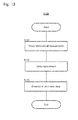
- the three-dimensional data creating step S120 can be carried out as shown in Fig. 13 for example. That is, the three-dimensional data creating step S120 includes a three-dimensional measurement step S121, a data replacement step S122, and an abutment data creating step S123.
- the three-dimensional measurement step S121 is a step of carrying out a three-dimensional measurement of a surface configuration of inside of the oral cavity where the scanning jig 10 is attached. This step makes it possible to obtain the shape of the surrounding of the area in the oral cavity where the scanning jig 10 is attached, and the shape of the scanning jig 10 attached inside the oral cavity can be obtained as three-dimensional data.
- the three-dimensional data of inside of the oral cavity can be obtained by means of a three-dimensional measurement apparatus for inside of oral cavity.
- the data replacement step S122 is a step of replacing the corresponding portion of the three-dimensional data obtained in the three-dimensional measurement step S121, with a three-dimensional shape data of the artificial tooth root and a three-dimensional shape data of the scanning jig 10 prepared in advance. That is, the three-dimensional shape data of the scanning jig prepared in advance is replaced in a manner to apply to the portion where the scanning jig is arranged in the three-dimensional data of the inside of the oral cavity. Also, the three-dimensional data of the artificial tooth root prepared in advance is applied to the portion of the artificial tooth root whose position can be obtained because the artificial tooth root is fitted with the scanning jig.
- the end surface 11b including the inclined surface 11c of the scanning jig 10 has a large dimension, whereby the replacement accuracy of the scanning jig 10 in the axial direction (longitudinal direction) is improved. Also, the shape of the inclined surface 11c makes it possible to improve the data replacement accuracy in the rotational direction, and to obtain information such as the kind of the artificial tooth root embedded to the patient.
- the abutment data creating step S123 is a step of creating a shape data of the abutment which is suitable to the patient, based on the obtained three-dimensional shape data. Since the replacement is carried out with a good accuracy especially in the data replacement step S122, the improvement in accuracy is adequately reflected to the abutment data, whereby it is possible to create the abutment data matched well to the patient.
- the abutment producing step S130 is a step of producing an abutment based on the three-dimensional shape data created in the three-dimensional data creating step S120 described above. In this step, for example, an abutment is produced with a high accuracy by providing the three-dimensional data to an NC machine tool such as a machining center.
- Fig. 14 shows a situation in which the scanning jig 110 according to another embodiment is attached to an analog model in which an analog 120 is embedded.
- Fig. 14 is a view seen from the same viewpoint as in Fig. 8 .
- the scanning jig 10 described above has a configuration in which the fitting part 11d is projected from a part of the end surface 11e of the main body 11 and the fitted part 20d is formed to the analog 20, the fitted part 20d being cut off so that the fitting part 11d can be inserted.
- the fitted part 111d is formed in a manner to be cut off in the axial direction on a hollow part 11a side of the end surface 11e of a main body 111.
- the protrusion 11f is formed to a part of the end surface 11e as in the scanning jig 10.
- a fitting part 120d having a cylindrical shape is provided to a part of the end surface 20b of the analog 120 in a direction extending the analog 120 from a hollow part 20a side.
- a groove 20c for inserting the protrusion 11f is provided to a part of the end surface 20b.
- This configuration of the scanning jig 110 is based on the configuration of the end portion of the analog 120. That is, as can be seen from Fig. 14 , the basic structure of the analog 120 is same as that of the analog 20 described above. However, since the analog 120 is provided with the projecting fitting part 120d, corresponding to the fitting part 120d, a fitted part 111d is provided to a main body 111 side of the scanning jig 110.
- the scanning jig 110 described above exerts the same effect as that of the scanning jig 10, for example the end surface of the fitting part 120d does not have contact with the main body 111.
Landscapes
- Health & Medical Sciences (AREA)
- General Health & Medical Sciences (AREA)
- Dentistry (AREA)
- Epidemiology (AREA)
- Life Sciences & Earth Sciences (AREA)
- Animal Behavior & Ethology (AREA)
- Oral & Maxillofacial Surgery (AREA)
- Public Health (AREA)
- Veterinary Medicine (AREA)
- Orthopedic Medicine & Surgery (AREA)
- Physics & Mathematics (AREA)
- Optics & Photonics (AREA)
- Dental Tools And Instruments Or Auxiliary Dental Instruments (AREA)
- Dental Prosthetics (AREA)
Applications Claiming Priority (2)
| Application Number | Priority Date | Filing Date | Title |
|---|---|---|---|
| JP2012142776 | 2012-06-26 | ||
| PCT/JP2013/063596 WO2014002632A1 (ja) | 2012-06-26 | 2013-05-15 | スキャニングジグ |
Publications (2)
| Publication Number | Publication Date |
|---|---|
| EP2865352A1 true EP2865352A1 (de) | 2015-04-29 |
| EP2865352A4 EP2865352A4 (de) | 2016-01-20 |
Family
ID=49782804
Family Applications (1)
| Application Number | Title | Priority Date | Filing Date |
|---|---|---|---|
| EP13810242.1A Withdrawn EP2865352A4 (de) | 2012-06-26 | 2013-05-15 | Abtastende einspannvorrichtung |
Country Status (4)
| Country | Link |
|---|---|
| US (1) | US9549790B2 (de) |
| EP (1) | EP2865352A4 (de) |
| JP (1) | JP5755370B2 (de) |
| WO (1) | WO2014002632A1 (de) |
Cited By (2)
| Publication number | Priority date | Publication date | Assignee | Title |
|---|---|---|---|---|
| EP3400899A4 (de) * | 2016-03-08 | 2019-09-11 | Esteban Xam-Mar Mangrane | Vorrichtung zum intraoralen scannen zur digitalen erfassung der position eines zahnimplantats mittels eines scanners |
| WO2022128407A1 (de) * | 2020-12-18 | 2022-06-23 | Dental Direkt GmbH | Ausrichtungshilfskörper, dessen verwendung, cad-datensatz und dentalscanner |
Family Cites Families (18)
| Publication number | Priority date | Publication date | Assignee | Title |
|---|---|---|---|---|
| US4758160A (en) | 1986-11-20 | 1988-07-19 | Isis International, Inc. | Dental implant |
| JP3658441B2 (ja) * | 1996-02-26 | 2005-06-08 | 譲治 田中 | キャップ式磁性アタッチメント |
| US6790040B2 (en) * | 1999-11-10 | 2004-09-14 | Implant Innovations, Inc. | Healing components for use in taking impressions and methods for making the same |
| SE522965C2 (sv) | 2000-12-29 | 2004-03-16 | Nobel Biocare Ab | Anordning för att åstadkomma lägesbestämning |
| ITTO20030575A1 (it) * | 2003-07-25 | 2005-01-26 | Acom S R L | Procedimento per la fabbricazione di travate di protesi dentarie del tipo avvitato ad una pluralita' di impianti osteo-integrati nell'osso mandibolare o mascellare. |
| BE1015916A3 (nl) * | 2004-02-25 | 2005-11-08 | Clerck Rene De | Werkwijze en markeerelement voor het bepalen van de positie van een dentaal implantaat. |
| JP2006271767A (ja) * | 2005-03-30 | 2006-10-12 | Gc Corp | 歯科インプラント用磁性アタッチメント |
| DE102006021476B3 (de) | 2006-05-09 | 2007-10-25 | Profim Ltd. | Magnetisches Abdrucksystem |
| DE102006052419A1 (de) * | 2006-11-07 | 2008-05-08 | Aepsilon Rechteverwaltungs Gmbh | Verfahren zum Erfassen von Implantaten |
| TWI463969B (zh) * | 2007-10-22 | 2014-12-11 | Design method of support tooth | |
| JP5195285B2 (ja) * | 2007-11-01 | 2013-05-08 | 日立金属株式会社 | インプラント用キーパー及びその組立体 |
| DE102007056820A1 (de) * | 2007-11-23 | 2009-06-18 | Sirona Dental Systems Gmbh | Messkörper für ein Implantat und Verfahren zur Erstellung einer 3D-Messaufnahme |
| JP5220626B2 (ja) * | 2009-01-06 | 2013-06-26 | 株式会社ジーシー | インプラント用アバットメントに対するキーパーの咬合面側の外周位置の三次元データ作成方法 |
| EP2218423B1 (de) * | 2009-02-12 | 2012-05-02 | Straumann Holding AG | Bestimmen der Position und der Ausrichtung eines Zahnimplantats |
| ES2450142T3 (es) * | 2009-02-26 | 2014-03-24 | Nobel Biocare Services Ag | Dispositivo para indicar la posición y la orientación de un implante dental |
| DE102009014013B4 (de) * | 2009-03-23 | 2015-03-26 | Bego Implant Systems Gmbh & Co. Kg | Erfassungshilfskörper und dessen Verwendung zur Erfassung der Lage und Ausrichtung eines Implantats |
| DK2462893T3 (da) * | 2010-12-07 | 2014-06-30 | Biomet 3I Llc | Universel scanningsdel til anvendelse på dentalimplantat og dentalimplantat-analoge |
| WO2012126475A1 (en) * | 2011-03-18 | 2012-09-27 | Elos Medtech Pinol A/S | Dental abutment for oral scanning |
-
2013
- 2013-05-15 JP JP2014522477A patent/JP5755370B2/ja not_active Expired - Fee Related
- 2013-05-15 US US14/401,654 patent/US9549790B2/en active Active
- 2013-05-15 WO PCT/JP2013/063596 patent/WO2014002632A1/ja not_active Ceased
- 2013-05-15 EP EP13810242.1A patent/EP2865352A4/de not_active Withdrawn
Cited By (3)
| Publication number | Priority date | Publication date | Assignee | Title |
|---|---|---|---|---|
| EP3400899A4 (de) * | 2016-03-08 | 2019-09-11 | Esteban Xam-Mar Mangrane | Vorrichtung zum intraoralen scannen zur digitalen erfassung der position eines zahnimplantats mittels eines scanners |
| WO2022128407A1 (de) * | 2020-12-18 | 2022-06-23 | Dental Direkt GmbH | Ausrichtungshilfskörper, dessen verwendung, cad-datensatz und dentalscanner |
| EP4262616A1 (de) * | 2020-12-18 | 2023-10-25 | Dental Direkt GmbH | Ausrichtungshilfskörper, dessen verwendung, cad-datensatz und dentalscanner |
Also Published As
| Publication number | Publication date |
|---|---|
| JP5755370B2 (ja) | 2015-07-29 |
| US9549790B2 (en) | 2017-01-24 |
| EP2865352A4 (de) | 2016-01-20 |
| WO2014002632A1 (ja) | 2014-01-03 |
| US20150140514A1 (en) | 2015-05-21 |
| JPWO2014002632A1 (ja) | 2016-05-30 |
Similar Documents
| Publication | Publication Date | Title |
|---|---|---|
| US20140051038A1 (en) | Method of creating an accurate bone and soft-tissue digital dental model | |
| KR101093512B1 (ko) | 임플란트용 어버트먼트 소재 | |
| US8105081B2 (en) | Surgical drill guide and index system | |
| KR101160121B1 (ko) | 치과용 임플란트 | |
| EP2529692B1 (de) | Zahnstütze und keramischer Block oder keramische Zahnprothese | |
| US20150150684A1 (en) | Method for manufacturing a template to adapt the shape of a bone defect in a jaw to a bone superstructure | |
| KR200482232Y1 (ko) | 치아 임플란트 시술용 서지컬 가이드 | |
| JP5220626B2 (ja) | インプラント用アバットメントに対するキーパーの咬合面側の外周位置の三次元データ作成方法 | |
| US9549790B2 (en) | Scanning jig | |
| WO2008089347A2 (en) | Depth gauge for use in dental implants | |
| KR101705871B1 (ko) | 임플란트 가이드 어셈블리 | |
| JP5937401B2 (ja) | スキャニングジグ | |
| US20140297232A1 (en) | Scanning instrument | |
| JP2007222225A (ja) | 連結体及びそれを用いた歯科用補綴物の作製方法 | |
| US20110136079A1 (en) | Abutment for dental magnetic attachment | |
| US20130108987A1 (en) | Analog positioner | |
| JP2008086467A (ja) | 支台歯模型の保持具 | |
| JP2020531069A (ja) | ブランクの配置方法 | |
| EP3628269A1 (de) | Treiber zum einbetten einer künstlichen zahnwurzel und künstliche zahnwurzel mit treiber | |
| KR20160003528A (ko) | 치과 치료용 보철물 제작을 위한 지그 및 그 지그를 이용한 치과 치료용 보철물 제작방법 | |
| KR20220013194A (ko) | 인공치아 및 그 제조 방법 | |
| JP3176616U (ja) | インプラント穴形成用ドリル | |
| TWI826521B (zh) | 用於形成義齒之坯料及製造義齒之方法 | |
| CN119486681A (zh) | 用于制备牙科假体的方法和可扫描临时基牙 | |
| GB2640830A (en) | Dental surgery apparatus |
Legal Events
| Date | Code | Title | Description |
|---|---|---|---|
| PUAI | Public reference made under article 153(3) epc to a published international application that has entered the european phase |
Free format text: ORIGINAL CODE: 0009012 |
|
| 17P | Request for examination filed |
Effective date: 20141121 |
|
| AK | Designated contracting states |
Kind code of ref document: A1 Designated state(s): AL AT BE BG CH CY CZ DE DK EE ES FI FR GB GR HR HU IE IS IT LI LT LU LV MC MK MT NL NO PL PT RO RS SE SI SK SM TR |
|
| AX | Request for extension of the european patent |
Extension state: BA ME |
|
| DAX | Request for extension of the european patent (deleted) | ||
| RA4 | Supplementary search report drawn up and despatched (corrected) |
Effective date: 20151223 |
|
| RIC1 | Information provided on ipc code assigned before grant |
Ipc: A61C 13/34 20060101ALI20151217BHEP Ipc: A61C 8/00 20060101AFI20151217BHEP |
|
| 17Q | First examination report despatched |
Effective date: 20180503 |
|
| 17Q | First examination report despatched |
Effective date: 20180503 |
|
| 18W | Application withdrawn |
Effective date: 20180427 |