EP2865294A1 - Device for vertically extending a screen using a gas cylinder - Google Patents
Device for vertically extending a screen using a gas cylinder Download PDFInfo
- Publication number
- EP2865294A1 EP2865294A1 EP14190372.4A EP14190372A EP2865294A1 EP 2865294 A1 EP2865294 A1 EP 2865294A1 EP 14190372 A EP14190372 A EP 14190372A EP 2865294 A1 EP2865294 A1 EP 2865294A1
- Authority
- EP
- European Patent Office
- Prior art keywords
- link
- screen
- movable arm
- frame
- guide
- Prior art date
- Legal status (The legal status is an assumption and is not a legal conclusion. Google has not performed a legal analysis and makes no representation as to the accuracy of the status listed.)
- Granted
Links
- 238000013519 translation Methods 0.000 claims description 5
- 238000006073 displacement reaction Methods 0.000 description 11
- 238000012550 audit Methods 0.000 description 7
- 238000003780 insertion Methods 0.000 description 4
- 230000037431 insertion Effects 0.000 description 4
- 229910000831 Steel Inorganic materials 0.000 description 3
- 239000004760 aramid Substances 0.000 description 3
- 229920003235 aromatic polyamide Polymers 0.000 description 3
- 239000010959 steel Substances 0.000 description 3
- 238000012423 maintenance Methods 0.000 description 2
- 230000005540 biological transmission Effects 0.000 description 1
- 238000013016 damping Methods 0.000 description 1
- 238000011161 development Methods 0.000 description 1
- 230000018109 developmental process Effects 0.000 description 1
- 238000005516 engineering process Methods 0.000 description 1
- 239000000463 material Substances 0.000 description 1
- 238000000034 method Methods 0.000 description 1
- 238000011084 recovery Methods 0.000 description 1
- 239000004753 textile Substances 0.000 description 1
Images


Classifications
-
- A—HUMAN NECESSITIES
- A47—FURNITURE; DOMESTIC ARTICLES OR APPLIANCES; COFFEE MILLS; SPICE MILLS; SUCTION CLEANERS IN GENERAL
- A47B—TABLES; DESKS; OFFICE FURNITURE; CABINETS; DRAWERS; GENERAL DETAILS OF FURNITURE
- A47B21/00—Tables or desks for office equipment, e.g. typewriters, keyboards
- A47B21/007—Tables or desks for office equipment, e.g. typewriters, keyboards with under-desk displays, e.g. displays being viewable through a transparent working surface of the table or desk
- A47B21/0073—Tables or desks for office equipment, e.g. typewriters, keyboards with under-desk displays, e.g. displays being viewable through a transparent working surface of the table or desk liftable above the desk top
-
- A—HUMAN NECESSITIES
- A47—FURNITURE; DOMESTIC ARTICLES OR APPLIANCES; COFFEE MILLS; SPICE MILLS; SUCTION CLEANERS IN GENERAL
- A47B—TABLES; DESKS; OFFICE FURNITURE; CABINETS; DRAWERS; GENERAL DETAILS OF FURNITURE
- A47B81/00—Cabinets or racks specially adapted for other particular purposes, e.g. for storing guns or skis
- A47B81/06—Furniture aspects of radio, television, gramophone, or record cabinets
- A47B81/061—Furniture aspects of radio, television, gramophone, or record cabinets the device supports being adjustable
- A47B81/064—Furniture aspects of radio, television, gramophone, or record cabinets the device supports being adjustable vertically
-
- F—MECHANICAL ENGINEERING; LIGHTING; HEATING; WEAPONS; BLASTING
- F16—ENGINEERING ELEMENTS AND UNITS; GENERAL MEASURES FOR PRODUCING AND MAINTAINING EFFECTIVE FUNCTIONING OF MACHINES OR INSTALLATIONS; THERMAL INSULATION IN GENERAL
- F16M—FRAMES, CASINGS OR BEDS OF ENGINES, MACHINES OR APPARATUS, NOT SPECIFIC TO ENGINES, MACHINES OR APPARATUS PROVIDED FOR ELSEWHERE; STANDS; SUPPORTS
- F16M11/00—Stands or trestles as supports for apparatus or articles placed thereon Stands for scientific apparatus such as gravitational force meters
- F16M11/02—Heads
- F16M11/04—Means for attachment of apparatus; Means allowing adjustment of the apparatus relatively to the stand
- F16M11/043—Allowing translations
- F16M11/046—Allowing translations adapted to upward-downward translation movement
-
- F—MECHANICAL ENGINEERING; LIGHTING; HEATING; WEAPONS; BLASTING
- F16—ENGINEERING ELEMENTS AND UNITS; GENERAL MEASURES FOR PRODUCING AND MAINTAINING EFFECTIVE FUNCTIONING OF MACHINES OR INSTALLATIONS; THERMAL INSULATION IN GENERAL
- F16M—FRAMES, CASINGS OR BEDS OF ENGINES, MACHINES OR APPARATUS, NOT SPECIFIC TO ENGINES, MACHINES OR APPARATUS PROVIDED FOR ELSEWHERE; STANDS; SUPPORTS
- F16M13/00—Other supports for positioning apparatus or articles; Means for steadying hand-held apparatus or articles
- F16M13/02—Other supports for positioning apparatus or articles; Means for steadying hand-held apparatus or articles for supporting on, or attaching to, an object, e.g. tree, gate, window-frame, cycle
-
- F—MECHANICAL ENGINEERING; LIGHTING; HEATING; WEAPONS; BLASTING
- F16—ENGINEERING ELEMENTS AND UNITS; GENERAL MEASURES FOR PRODUCING AND MAINTAINING EFFECTIVE FUNCTIONING OF MACHINES OR INSTALLATIONS; THERMAL INSULATION IN GENERAL
- F16M—FRAMES, CASINGS OR BEDS OF ENGINES, MACHINES OR APPARATUS, NOT SPECIFIC TO ENGINES, MACHINES OR APPARATUS PROVIDED FOR ELSEWHERE; STANDS; SUPPORTS
- F16M2200/00—Details of stands or supports
- F16M2200/04—Balancing means
- F16M2200/047—Balancing means for balancing translational movement of the head
Definitions
- the invention relates to a vertical screen output device with a gas cylinder, and more particularly to a device adapted to adapt to different screen models.
- the present invention aims to solve the aforementioned difficulties.
- the movement of the screen between the retracted position and the working position is provided by the cylinder independently.
- the cylinder also makes it possible to dampen the displacement of the screen autonomously.
- the adjustment system makes it possible to adapt the force of the jack to the weight of the screen to be moved.
- the displacement device can thus be freed from any additional actuator. More particularly, the displacement device makes it possible to dispense with a jack controlled by an actuator whose power would be adjustable and which would thus control the force of the jack. Indeed, in the present displacement device, this function is provided by the adjustment system.
- said movable arm is rotatable relative to said frame and said support.
- the jack is rotatable relative to said movable arm and said frame.
- the displacement of the screen between the retracted position and the working position is linear.
- the jack is a gas cylinder or gas spring.
- said movable arm is manufactured in one piece.
- said movable arm can be made by an assembly of stamped parts and welded so as to form a shell.
- the second link is a rigid link.
- the first, second, third and fourth links are selected from the group comprising the pivot connection, the ball joint and the combination of a pivot connection and a slide connection.
- said second link is a combination of a pivot link and a slide link.
- said second link comprises a male portion and a female portion, said movable arm having an oblong slot at said second end of said movable arm, adapted to receive said male portion of said second link.
- the second link is a flexible link arranged to allow limited spacing between the second end of the movable arm and the screen support.
- the limited spacing can be obtained by limiting the spacing either by the action of a flexible deformable element of fixed length, or by the action of an elastically deformable element.
- the second link comprises a deformable element connected on the one hand to the second end of the movable arm, and on the other hand to the screen support.
- the deformable element is a flexible deformable element of fixed length.
- the deformable element is made of textile material.
- the deformable element is constituted by a belt.
- the flexible connection is an elastic connection.
- elastic connection is meant a link comprising a return function.
- An elastic connection makes it possible to smooth out the irregularities of tension and to make the use of the displacement device more flexible.
- the deformable element is an elastically deformable element.
- the deformable element is arranged to exert a return function.
- the belt may for example be made of rubber reinforced with steel or aramid son.
- the deformable element could also be constituted by a spring, a gas cylinder or an elastic segment.
- Such an elastic segment could also be made of rubber reinforced steel or aramid son.
- the elastic element is connected to the second end of the movable arm by a pivot connection.
- the elastic element is connected to the screen support by a pivot connection.
- the device allows the operator not to limit his choice screens whose weight is compatible with the lifting force of the cylinder.
- the present invention ensures a great adaptability of the device to technological developments.
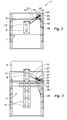
- FIGs 1a and 1b represent a workstation equipped with the device according to the invention.
- a workstation 1 in which the screen is in the retracted position in a chassis housing 3.
- the same workstation 1 is shown in which the screen 5 is out of its housing chassis 3.
- the screen 5 is in the retracted position in its housing 7.
- the screen 5 is out of its housing 7, in the working position.
- the screen 5 is fixed to a support 9 and attached to guide means, in this example, a slide 11.
- a movable arm 13 is connected at a first end to the frame 3 by a rigid connection 15.
- the movable arm 13 is also connected, at a second end, to the screen support 9 by a rigid link 17.
- a jack 19 is connected to the movable arm 13 via an adjustment system 21.
- the jack 19 is connected to the adjustment system 21 by the link 22.
- This adjustment system comprises a movable element 23 allowing the jack 19 it is positioned along the movable arm 13 between a first adjustment position 25 and a second adjustment position 27.
- the actuator can be positioned in the positioning range defined by the first adjustment position 25 and the second adjustment position 27. It can, in this embodiment, adopt an infinity of positions.
- the jack 19 is further connected to the frame 3 by a rigid connection 29.
- the adjustment system 21 facilitates the insertion or removal of the screen 5 from its compartment 7. Indeed, the position of the cylinder 19 along the movable arm 13 determines the position of the application point 31 of its force lifting. The distance between the point of application 31 of the lifting force of the jack 19 and the link 17 implies a moment 33 at the link 17. This moment 33 is opposed to the moment generated by the weight of the screen 5. It is therefore possible for an operator to facilitate removal or insertion of the screen 5 in its housing 7 by varying the position of the application point 31 of the action of the cylinder 19 and thus compensating the action of the weight of the screen 5 by the action of the cylinder 19 on the movable arm 13. This feature allows the device to adapt to a multitude of screens without the replacement of the cylinder 19 is necessary.
- the links 15, 17, 22, 29 may be chosen between the ball joint, the pivot link and a combination of a pivot link and a slide link.
- These connecting means comprise a female portion and a male portion.
- the link 17 is advantageously a combination of a pivot connection and a slide connection.
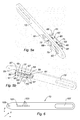
- FIGS. 4a, 4b and 5 represent the movable arm 13 and the adjustment system 21.
- the adjustment system 21 comprises a movable element 23, here comprising a screw 49.
- the screw 49 is connected to the movable arm 13 via a fixed element 51.
- This fixed element comprises a portion 53 intended to be fixed to the movable arm 13 and two portions 55, 57 comprising housings 59, 61 for receiving the movable member 23, here the screw 49, fixed by nuts 63, 65.
- the adjustment system 21 comprises a connecting element 67 making it possible to connect the jack 19 to the screw 49.
- a first portion 69 of the connecting element 67 comprises a housing 71 which is connected to the screw 49 and allowing a displacement of the point of application 31 of the force lifting cylinder 19 substantially parallel to the general direction of the movable arm 13.
- This rigid connection formed by the housing 71 and the screw 49 is a helical connection.
- a second portion 73 of the connecting element 67 comprises a housing 75 intended to accommodate the cylinder 19 by a rigid connection 22, here a pivot connection, the housing 75 constitutes the female part.
- the adjustment system 21 comprises a guiding system 66 of the connecting element 67.
- the guiding system 66 allows the translational guidance of the connecting element 67.
- the guiding system 66 comprises a guiding element, here a finger 68, integral with the connecting element 67.
- the longitudinal axis of the finger 68 is perpendicular to the longitudinal axis of the main portion 70 of the connecting element 67.
- the housing 71 accommodating the screw 49, is central relative to the finger 68 and to the main portion 70 of the connecting element 67.
- the guiding system also comprises an elongate housing 77 in the movable arm 13.
- the finger 68 is able to fit into the elongate housing 77.
- the finger 68 of the connecting element 67 has a parallelepipedal geometry in order to ensure a linear contact with the elongated housing 77 of the movable arm 13.
- the finger 68 makes it possible on the one hand to avoid the main part 70 of the connecting element to pivot during its reg or on actuation of the cylinder 19.
- the finger 68 allows the recovery of the forces by the movable arm 13. In fact, during the actuation of the cylinder 19, significant efforts are transmitted to the element link 68.
- the finger 68 thus makes it possible to reduce wear and strain rate.
- the contact between the surfaces of the finger 68 and the oblong slot 77 is plane, which optimizes the transmission of the forces to the movable arm 13.
- the fourth connection 22 is a ball joint connection and the male portion is constituted by the end piece 79 attached to the connecting element 67.
- the fixed element 51 comprises two attachment portions 81 and 83 making it possible to connect it to the mobile arm 13.
- the fixed element 51 also comprises a guide portion 85 substantially parallel to the main direction of the mobile arm 13.
- This guide portion 85 is connected to the fastening portions 81 and 83 through the intermediate portions 87 and 89.
- the intermediate portions 87 and 89 comprise the housings 59 and 61 to accommodate the screw 49.
- the screw 49 is located between the movable arm 13 and the guide portion 85 of the fixed element 51.
- the face 90 of the guide portion 85 of the fixed element 51 is adjacent to the connecting element 67.
- the guide portion 85 of the fixed element 51 also allows the translational guidance of the connecting element 67.
- An indicator 91 is attached to the connecting element 67.
- the connecting element 67 comprises, on its face 95 opposite its face 90, a graduation 97 corresponding to the weight of the screen 5.
- the adjustment system 21 comprises indexing means 101 of the position of the link 22 on the movable arm 13. These indexing means 101 are in the form of bearings, constituted here by housings 103 distributed along the movable arm 13, forming the female portion of the link 22. These housings 103 are able to accommodate the male portion of the link 22.
- the Figures 4a, 4b and 5 also represent a housing 105 constituting the female part of the link 15 at one end of the movable arm 13. At a second end, the movable arm 13 has an oblong slot 107 constituting the female part of the connecting means 17, thus allowing the vertical exit screen 5 of its compartment 7.
- the link 17 is composed of a pivot connection along the z axis and a slide connection along the x axis.
- the second link is a flexible link.
- the flexible link arranged to allow limited spacing between the second end of the movable arm 13 and the screen support 9.
- the limited spacing can be obtained by limiting the spacing either by the action of a flexible deformable element or by the action of an elastically deformable element.
- the flexible connection is provided by a deformable element 110 comprising here a belt 112.
- the belt 112 here has a low elasticity, which allows the damping of the movements of the screen.
- the belt is here made of rubber reinforced with steel wire or aramid.
- the belt 112 is connected to the second end of the mobile arm 13.
- the second end of the mobile arm 13 comprises, in this embodiment, two end portions 114, 116, symmetrical about a longitudinal plane of the movable arm 13. These portions end members 114, 116 each comprise a lumen in which a shaft 118 is attached.
- the belt 112 is disposed around the shaft 118.
- the belt 112 is further connected to the screen support 9 by a pivot connection.
- the screen support 9 comprises a shaft at the end of which is fixed a nut 120, thus forming a receiving groove of the belt 112.
- the present invention is not limited to the embodiments described and shown, provided for illustrative and non-limiting examples.
Abstract
La présente invention concerne un dispositif de déplacement d'un écran (5) entre une première position dite « escamotée » et une deuxième position dite « de travail » par rapport à un châssis (3) ou une partie de meuble comprenant : - un support d'écran (9) sur lequel ledit écran (5) est destiné à être rapporté ; - un guide (11) du mouvement dudit écran (5) rapporté sur ledit support d'écran (9) relativement audit châssis (3), apte à guider ledit écran (5) entre ladite position escamotée dans un logement (7) dudit châssis (3) et ladite position de travail ; - un bras mobile (13) relié d'une part, en une première extrémité, audit châssis (3) par une première liaison (15) rigide ; et d'autre part, en une deuxième extrémité, audit support d'écran (9) par une deuxième liaison (17) ; - un vérin (19) relié d'une part audit châssis (3) par une troisième liaison rigide (29) ; et d'autre part audit bras mobile (13) par une quatrième liaison (22) rigide ; - un système de réglage (21) du positionnement de ladite quatrième liaison (22) entre une première position de réglage (25) et une deuxième position de réglage (27) le long dudit bras mobile (13), de manière à adapter le moment induit sur ladite deuxième liaison (17) par l'action dudit vérin (19) au moment induit par le poids dudit écran (5) sur ladite deuxième liaison (17).The present invention relates to a device for moving a screen (5) between a first so-called "retracted" position and a second so-called "working" position with respect to a frame (3) or part of a piece of furniture comprising: - a screen support (9) on which said screen (5) is intended to be reported; a guide (11) for the movement of said screen (5) attached to said screen support (9) relative to said frame (3), able to guide said screen (5) between said retracted position in a housing (7) of said frame (3) and said working position; - A movable arm (13) connected firstly at a first end to said frame (3) by a first link (15) rigid; and secondly, at a second end, to said screen support (9) by a second link (17); - A cylinder (19) connected on the one hand to said frame (3) by a third rigid connection (29); and on the other hand said movable arm (13) by a fourth link (22) rigid; an adjustment system (21) for positioning said fourth link (22) between a first setting position (25) and a second setting position (27) along said movable arm (13), so as to adapt the moment induced on said second link (17) by the action of said jack (19) at the moment induced by the weight of said screen (5) on said second link (17).
Description
L'invention se rapporte à un dispositif de sortie verticale d'écran grâce à un vérin à gaz, et plus particulièrement à un dispositif apte à s'adapter à différents modèles d'écran.The invention relates to a vertical screen output device with a gas cylinder, and more particularly to a device adapted to adapt to different screen models.
Sont connus de l'art antérieur différents dispositifs comprenant un logement permettant d'héberger un écran et des moyens permettant la sortie de cet écran en position de travail et permettant son retrait dans le logement en position escamotée. Ces dispositifs sont généralement adaptés à une configuration précise d'écran. Généralement, la force d'expulsion de l'écran de son logement est déterminée par un actionneur dont la puissance est fixe.Are known from the prior art various devices comprising a housing for housing a screen and means for the output of this screen in the working position and allowing its removal in the housing in the retracted position. These devices are generally adapted to a precise screen configuration. Generally, the force of expulsion of the screen from its housing is determined by an actuator whose power is fixed.
En cas d'évolution des technologies et des besoins, le remplacement de l'écran implique donc le remplacement de l'actionneur, ce qui peut engendrer des coûts importants.In the event of changing technologies and needs, the replacement of the screen therefore implies the replacement of the actuator, which can generate significant costs.
La présente invention a pour objectif de résoudre les difficultés susmentionnées.The present invention aims to solve the aforementioned difficulties.
Á cet effet, la présente invention a pour objet un dispositif de déplacement d'un écran entre une première position dite « escamotée » et une deuxième position dite « de travail » par rapport à un châssis ou une partie de meuble comprenant :
- un support d'écran sur lequel ledit écran est destiné à être rapporté ;
- un guide du mouvement de l'écran rapporté sur ledit support d'écran relativement audit châssis, apte à guider ledit écran entre ladite position escamotée dans un logement dudit châssis et ladite position de travail ;
- un bras mobile relié d'une part, en une première extrémité, audit châssis par une première liaison rigide et d'autre part, en une deuxième extrémité, audit support d'écran par une deuxième liaison ;
- un vérin relié d'une part audit châssis par une troisième liaison rigide, et d'autre part audit bras mobile par une quatrième liaison rigide ;
- un système de réglage du positionnement de ladite quatrième liaison entre une première position de réglage et une deuxième position de réglage le long dudit bras mobile, de manière à adapter le moment induit sur ladite deuxième liaison par l'action dudit vérin au moment induit par le poids dudit écran sur ladite deuxième liaison, et ainsi faciliter le retrait ou l'insertion dudit écran dans ledit logement.
- a screen support on which said screen is to be reported;
- a guide to the movement of the screen attached to said screen support relative to said frame, able to guide said screen between said retracted position in a housing of said frame and said working position;
- a movable arm connected on the one hand, at a first end, to said frame by a first rigid connection and secondly, at a second end, to said screen support by a second link;
- a jack connected on the one hand to said chassis by a third rigid connection, and on the other hand to said movable arm by a fourth rigid connection;
- a system for adjusting the positioning of said fourth link between a first adjustment position and a second adjustment position along said movable arm, so as to adapt the moment induced on said second connection by the action of said actuator at the moment induced by the weight of said screen on said second link, and thus facilitate removal or insertion of said screen in said housing.
Grâce aux dispositions selon l'invention, le déplacement de l'écran entre la position escamotée et la position de travail est assuré par le vérin de manière autonome. Le vérin permet également d'amortir le déplacement de l'écran de manière autonome. Le système de réglage permet d'adapter la force du vérin au poids de l'écran à déplacer. Le dispositif de déplacement peut donc s'affranchir de tout actionneur supplémentaire. Plus particulièrement, le dispositif de déplacement permet de s'affranchir d'un vérin commandé par un actionneur dont la puissance serait réglable et qui commanderait ainsi la force du vérin. En effet, dans le présent dispositif de déplacement, cette fonction est assurée par le système de réglage. Ces dispositions permettent une simplicité d'utilisation et d'entretien du dispositif de déplacement.Thanks to the arrangements according to the invention, the movement of the screen between the retracted position and the working position is provided by the cylinder independently. The cylinder also makes it possible to dampen the displacement of the screen autonomously. The adjustment system makes it possible to adapt the force of the jack to the weight of the screen to be moved. The displacement device can thus be freed from any additional actuator. More particularly, the displacement device makes it possible to dispense with a jack controlled by an actuator whose power would be adjustable and which would thus control the force of the jack. Indeed, in the present displacement device, this function is provided by the adjustment system. These arrangements allow simplicity of use and maintenance of the moving device.
Avantageusement, ledit bras mobile est mobile en rotation par rapport audit châssis et audit support. Selon une caractéristique optionnelle de l'invention, le vérin est mobile en rotation par rapport audit bras mobile et audit châssis.Advantageously, said movable arm is rotatable relative to said frame and said support. According to an optional feature of the invention, the jack is rotatable relative to said movable arm and said frame.
Selon un aspect de l'invention, le déplacement de l'écran entre la position escamotée et la position de travail est linéaire.According to one aspect of the invention, the displacement of the screen between the retracted position and the working position is linear.
Selon un aspect de l'invention, le vérin est un vérin à gaz ou ressort à gaz.According to one aspect of the invention, the jack is a gas cylinder or gas spring.
Selon un mode de réalisation du dispositif selon l'invention, ledit bras mobile est fabriqué en une seule pièce. Selon un autre mode de réalisation, ledit bras mobile peut être réalisé par un assemblage de pièces embouties puis soudées de sorte à former une coquille.According to one embodiment of the device according to the invention, said movable arm is manufactured in one piece. According to another embodiment, said movable arm can be made by an assembly of stamped parts and welded so as to form a shell.
Selon un aspect de l'invention, la deuxième liaison est une liaison rigide.According to one aspect of the invention, the second link is a rigid link.
Selon un aspect de l'invention, les première, deuxième, troisième et quatrième liaisons sont choisies dans le groupe comprenant la liaison pivot, la liaison rotule et la combinaison d'une liaison pivot et d'une liaison glissière.According to one aspect of the invention, the first, second, third and fourth links are selected from the group comprising the pivot connection, the ball joint and the combination of a pivot connection and a slide connection.
Selon un aspect de l'invention ladite deuxième liaison est une combinaison d'une liaison pivot et d'une liaison glissière.According to one aspect of the invention said second link is a combination of a pivot link and a slide link.
Selon un aspect de l'invention, ladite deuxième liaison comporte une portion mâle et une portion femelle, ledit bras mobile présentant une lumière oblongue en ladite deuxième extrémité dudit bras mobile, apte à recevoir ladite portion mâle de ladite deuxième liaison.According to one aspect of the invention, said second link comprises a male portion and a female portion, said movable arm having an oblong slot at said second end of said movable arm, adapted to receive said male portion of said second link.
Selon un aspect de l'invention, la deuxième liaison est une liaison souple agencée pour autoriser un écartement limité entre la deuxième extrémité du bras mobile et le support d'écran.According to one aspect of the invention, the second link is a flexible link arranged to allow limited spacing between the second end of the movable arm and the screen support.
L'écartement limité peut être obtenu en bornant l'écartement soit par l'action d'un élément déformable souple de longueur fixe, soit par l'action d'un élément déformable élastiquement.The limited spacing can be obtained by limiting the spacing either by the action of a flexible deformable element of fixed length, or by the action of an elastically deformable element.
Ces dispositions selon l'invention permettent une diminution des frottements et contraintes du dispositif de déplacement. La capacité de levage du dispositif de déplacement est ainsi optimisée. Les bruits de fonctionnement du dispositif sont moindres. L'entretien est également facilité car il n'est plus nécessaire de lubrifier la deuxième liaison.These arrangements according to the invention allow a reduction of friction and constraints of the displacement device. The lifting capacity of the displacement device is thus optimized. Operating noise of the device is lower. Maintenance is also facilitated because it is no longer necessary to lubricate the second link.
Selon un aspect de l'invention, la deuxième liaison comprend un élément déformable relié d'une part à la deuxième extrémité du bras mobile, et d'autre part au support d'écran.According to one aspect of the invention, the second link comprises a deformable element connected on the one hand to the second end of the movable arm, and on the other hand to the screen support.
Selon un aspect de l'invention, l'élément déformable est un élément déformable souple de longueur fixe.According to one aspect of the invention, the deformable element is a flexible deformable element of fixed length.
Selon un aspect de l'invention, l'élément déformable est réalisé en matière textile.According to one aspect of the invention, the deformable element is made of textile material.
Avantageusement, l'élément déformable est constitué par une courroie.Advantageously, the deformable element is constituted by a belt.
Selon un aspect de l'invention, la liaison souple est une liaison élastique.According to one aspect of the invention, the flexible connection is an elastic connection.
On entend par liaison élastique une liaison comportant une fonction de rappel.By elastic connection is meant a link comprising a return function.
Une liaison élastique permet de lisser les irrégularités de tension et d'assouplir l'utilisation du dispositif de déplacement.An elastic connection makes it possible to smooth out the irregularities of tension and to make the use of the displacement device more flexible.
Selon un aspect de l'invention, l'élément déformable est un élément déformable élastiquement.According to one aspect of the invention, the deformable element is an elastically deformable element.
Selon un aspect de l'invention, l'élément déformable est agencé pour exercer une fonction de rappel.According to one aspect of the invention, the deformable element is arranged to exert a return function.
Selon un aspect de l'invention, la courroie peut par exemple être réalisée en caoutchouc armé de fils d'acier ou d'aramide.According to one aspect of the invention, the belt may for example be made of rubber reinforced with steel or aramid son.
Selon un aspect de l'invention, l'élément déformable pourrait également être constitué par un ressort, un vérin à gaz ou un segment élastique.According to one aspect of the invention, the deformable element could also be constituted by a spring, a gas cylinder or an elastic segment.
Un tel segment élastique pourrait également être réalisé en caoutchouc armé de fils d'acier ou d'aramide.Such an elastic segment could also be made of rubber reinforced steel or aramid son.
Selon un aspect de l'invention, l'élément élastique est relié à la deuxième extrémité du bras mobile par une liaison pivot.According to one aspect of the invention, the elastic element is connected to the second end of the movable arm by a pivot connection.
Selon un aspect de l'invention, l'élément élastique est relié au support d'écran par une liaison pivot.According to one aspect of the invention, the elastic element is connected to the screen support by a pivot connection.
Selon des caractéristiques optionnelles du dispositif selon l'invention :
- ledit système de réglage comporte :
- un élément mobile, sur lequel se rapporte ledit vérin par ladite quatrième liaison, agencé pour positionner ledit vérin sur ledit bras mobile ;
- d'un élément fixe reliant ledit élément mobile audit bras mobile ;
- ledit élément mobile comprend une vis ;
- ledit élément fixe comprend une portion destinée à être fixée audit bras mobile, et une portion comprenant un logement destiné à accueillir ledit élément mobile ;
- ledit système de réglage comprend des moyens d'indexation de la position de ladite quatrième liaison sur ledit bras mobile ;
- ladite quatrième liaison comprend une portion mâle et une portion femelle, ladite portion femelle étant constituée de paliers aptes à accueillir ladite portion mâle de ladite quatrième liaison de manière amovible ;
- un élément de liaison est disposé entre ledit quatrième moyen de liaison et ledit système de réglage ;
- avantageusement, ledit élément de liaison comporte une partie comprenant un logement destiné à accueillir ledit élément mobile ;
- selon un mode de réalisation de l'invention, ledit élément de liaison comporte une partie comprenant un logement destiné à accueillir ledit vérin ;
- ledit système de réglage comprend un système de guidage en translation de l'élément de liaison permettant de reprendre les efforts du vérin sur l'élément de liaison et de les transmettre au bras mobile ;
- ledit système de guidage comprend un élément de guidage et un logement oblong dudit bras mobile dans lequel est destiné à s'insérer ledit élément de guidage.
- said adjustment system comprises:
- a movable member, to which said cylinder refers by said fourth link, arranged to position said cylinder on said movable arm;
- a fixed element connecting said movable element to said movable arm;
- said movable member comprises a screw;
- said fixed element comprises a portion intended to be fixed to said movable arm, and a portion comprising a housing for accommodating said movable element;
- said adjustment system comprises means for indexing the position of said fourth link on said movable arm;
- said fourth link comprises a male portion and a female portion, said female portion consisting of bearings adapted to receive said male portion of said fourth link removably;
- a connecting element is disposed between said fourth connecting means and said adjusting system;
- advantageously, said connecting element comprises a part comprising a housing intended to receive said movable element;
- according to one embodiment of the invention, said connecting element comprises a portion comprising a housing for receiving said jack;
- said adjustment system comprises a translation guide system of the connecting element for taking up the forces of the cylinder on the connecting element and transmit them to the movable arm;
- said guiding system comprises a guiding element and an elongate housing of said movable arm in which said guiding element is to be inserted.
Ces caractéristiques permettent une grande facilité de mise en oeuvre du dispositif. Un opérateur peut aisément adapter le dispositif aux configurations d'une grande variété d'écran. En effet, le dispositif permet à l'opérateur de ne pas limiter ses choix aux écrans dont le poids est compatible avec la force de levage du vérin. La présente invention assure une grande adaptabilité du dispositif aux évolutions technologiques.These characteristics allow a great ease of implementation of the device. An operator can easily adapt the device to configurations of a wide variety of screens. Indeed, the device allows the operator not to limit his choice screens whose weight is compatible with the lifting force of the cylinder. The present invention ensures a great adaptability of the device to technological developments.
D'autres caractéristiques et avantages de la présente invention apparaîtront à la lumière de la description qui va suivre et à l'examen des figures ci-annexées, dans lesquelles :
- la
figure 1a représente un dispositif selon l'invention dans lequel l'écran est en position escamotée ; - la
figure 1b représente un dispositif selon l'invention dans lequel l'écran est en position de travail ; - la
figure 2 représente une coupe en vue arrière du dispositif selon l'invention lorsque l'écran est en position escamotée; - la
figure 3 représente une coupe en vue arrière du dispositif selon l'invention, lorsque l'écran est en position de travail ; - les
figures 4a et 4b représentent un bras mobile équipé d'un système de réglage selon un premier mode de réalisation de l'invention et ; - les
figures 5a et 5b représentent un deuxième mode de réalisation, dans laquelle le dispositif de réglage comprend un système de guidage en translation de l'élément de liaison ; - la
figure 6 représente un bras mobile équipé d'un système de réglage selon un troisième mode de réalisation de l'invention ; - la
figure 7 représente un bras mobile selon un quatrième mode de réalisation du dispositif de déplacement dans lequel la deuxième liaison est souple ; - les
figures 8a et 8b représentent le dispositif de déplacement en position de travail et en position escamotée respectivement, selon le quatrième mode de réalisation.
- the
figure 1a represents a device according to the invention in which the screen is in the retracted position; - the
figure 1b represents a device according to the invention in which the screen is in working position; - the
figure 2 represents a section in rear view of the device according to the invention when the screen is in the retracted position; - the
figure 3 represents a section in rear view of the device according to the invention, when the screen is in the working position; - the
Figures 4a and 4b represent a mobile arm equipped with a control system according to a first embodiment of the invention and; - the
Figures 5a and 5b represent a second embodiment, in which the adjusting device comprises a system for guiding the connecting element in translation; - the
figure 6 represents a mobile arm equipped with a control system according to a third embodiment of the invention; - the
figure 7 represents a movable arm according to a fourth embodiment of the displacement device in which the second link is flexible; - the
Figures 8a and 8b represent the displacement device in the working position and in the retracted position respectively, according to the fourth embodiment.
Les
En
Le système de réglage 21 permet de faciliter l'insertion ou le retrait de l'écran 5 de son compartiment 7. En effet, la position du vérin 19 le long du bras mobile 13 détermine la position du point d'application 31 de sa force de levage. La distance entre le point d'application 31 de la force de levage du vérin 19 et la liaison 17 implique un moment 33 au niveau de la liaison 17. Ce moment 33 est opposé au moment 35 engendré par le poids de l'écran 5. Il est donc possible pour un opérateur de faciliter le retrait ou l'insertion de l'écran 5 dans son logement 7 en faisant varier la position du point d'application 31 de l'action du vérin 19 et ainsi en compensant l'action du poids de l'écran 5 par l'action du vérin 19 sur le bras mobile 13. Cette caractéristique permet au dispositif de s'adapter à une multitude d'écrans sans que le remplacement du vérin 19 soit nécessaire.The
Les liaisons 15, 17, 22, 29 peuvent être choisies entre la liaison rotule, la liaison pivot et une combinaison d'une liaison pivot et d'une liaison glissière. Ces moyens de liaison comprennent une portion femelle et une portion mâle. La liaison 17 est avantageusement une combinaison d'une liaison pivot et d'une liaison glissière.The
Les
Dans un premier mode de réalisation, représenté en
Un deuxième mode de réalisation est représentée en
Dans ce mode de réalisation, la quatrième liaison 22 est une liaison rotule donc la partie mâle est constituée par l'embout 79 rapporté sur l'élément de liaison 67.In this embodiment, the
L'élément fixe 51 comprend deux portions de fixation 81 et 83 permettant de le relier au bras mobile 13. L'élément fixe 51 comprend également une portion de guidage 85, sensiblement parallèle à la direction principale du bras mobile 13. Cette portion de guidage 85 est reliée aux portions de fixation 81 et 83 par l'intermédiaire des portions intermédiaires 87 et 89. Les portions intermédiaires 87 et 89 comprennent les logements 59 et 61 permettant d'accueillir la vis 49. La vis 49 est située entre le bras mobile 13 et la portion de guidage 85 de l'élément fixe 51. La face 90 de la portion de guidage 85 de l'élément fixe 51 est adjacente l'élément de liaison 67. Ainsi, la portion de guidage 85 de l'élément fixe 51 permet également le guidage en translation de l'élément de liaison 67. Un indicateur 91 est rapporté sur l'élément de liaison 67. Il est adjacent au bord inférieur 93 de la portion de guidage 85 de l'élément de liaison 67. D'un point de vu transversal, il est au centre de l'élément de liaison 67. L'élément de liaison 67 comprend, sur sa face 95 opposée à sa face 90, une graduation 97 correspondant au poids de l'écran 5. Ainsi le positionnement de l'élément de liaison 67 le long de la vis 49 est facilité.The fixed
Un troisième mode de réalisation est représenté en
Les
Selon un quatrième mode de réalisation de l'invention représenté en
L'écartement limité peut être obtenu en bornant l'écartement soit par l'action d'un élément déformable souple, soit par l'action d'un élément déformable élastiquement.The limited spacing can be obtained by limiting the spacing either by the action of a flexible deformable element or by the action of an elastically deformable element.
Dans ce mode de réalisation, la liaison souple est assurée par un élément déformable 110 comprenant ici une courroie 112. La courroie 112 présente ici une faible élasticité, ce qui permet l'amortissement des mouvements de l'écran. La courroie est ici réalisée en caoutchouc armé de fils d'acier ou d'aramide.In this embodiment, the flexible connection is provided by a
La courroie 112 est reliée à la deuxième extrémité du bras mobile 13. La deuxième extrémité du bras mobile 13 comprend, dans ce mode de réalisation, deux portions d'extrémité 114, 116, symétriques selon un plan longitudinal du bras mobile 13. Ces portions d'extrémité 114, 116 comprennent chacune une lumière dans lesquelles un arbre 118 est fixé. La courroie 112 est disposée autour de l'arbre 118.The
La courroie 112 est reliée en outre au support d'écran 9 par une liaison pivot. Le support d'écran 9 comprend un arbre au bout duquel est fixé un écrou 120, formant ainsi une gorge de réception de la courroie 112.Bien entendu, la présente invention ne se limite pas aux modes de réalisation décrits et représentés, fournis à titre d'exemples illustratifs et non limitatifs.The
Claims (16)
Applications Claiming Priority (1)
| Application Number | Priority Date | Filing Date | Title |
|---|---|---|---|
| FR1360457A FR3012565B1 (en) | 2013-10-25 | 2013-10-25 | VERTICAL SCREEN OUTPUT DEVICE USING A GAS CYLINDER |
Publications (2)
| Publication Number | Publication Date |
|---|---|
| EP2865294A1 true EP2865294A1 (en) | 2015-04-29 |
| EP2865294B1 EP2865294B1 (en) | 2018-07-18 |
Family
ID=49876871
Family Applications (1)
| Application Number | Title | Priority Date | Filing Date |
|---|---|---|---|
| EP14190372.4A Active EP2865294B1 (en) | 2013-10-25 | 2014-10-24 | Device for vertically extending a screen using a gas cylinder |
Country Status (2)
| Country | Link |
|---|---|
| EP (1) | EP2865294B1 (en) |
| FR (1) | FR3012565B1 (en) |
Families Citing this family (1)
| Publication number | Priority date | Publication date | Assignee | Title |
|---|---|---|---|---|
| FR3084431B1 (en) * | 2018-07-24 | 2020-07-17 | Aldes Aeraulique | ADJUSTABLE ADJUSTMENT DEVICE FROM A FIRST END AND A SECOND END OF THE ADJUSTMENT DEVICE |
Citations (3)
| Publication number | Priority date | Publication date | Assignee | Title |
|---|---|---|---|---|
| US3431040A (en) * | 1967-08-22 | 1969-03-04 | Weber Knapp Co | Platform elevation control mechanism |
| EP1574150A1 (en) * | 2004-03-09 | 2005-09-14 | Avialec, SL | Flat screen ejection and retraction device |
| US20130257242A1 (en) * | 2012-03-27 | 2013-10-03 | Clinton Merle Bunch | Storage system |
Family Cites Families (2)
| Publication number | Priority date | Publication date | Assignee | Title |
|---|---|---|---|---|
| JPH01170141U (en) * | 1988-05-17 | 1989-12-01 | ||
| US6442799B1 (en) * | 1999-12-15 | 2002-09-03 | Carlos Duarte | Hinge |
-
2013
- 2013-10-25 FR FR1360457A patent/FR3012565B1/en not_active Expired - Fee Related
-
2014
- 2014-10-24 EP EP14190372.4A patent/EP2865294B1/en active Active
Patent Citations (3)
| Publication number | Priority date | Publication date | Assignee | Title |
|---|---|---|---|---|
| US3431040A (en) * | 1967-08-22 | 1969-03-04 | Weber Knapp Co | Platform elevation control mechanism |
| EP1574150A1 (en) * | 2004-03-09 | 2005-09-14 | Avialec, SL | Flat screen ejection and retraction device |
| US20130257242A1 (en) * | 2012-03-27 | 2013-10-03 | Clinton Merle Bunch | Storage system |
Also Published As
| Publication number | Publication date |
|---|---|
| EP2865294B1 (en) | 2018-07-18 |
| FR3012565B1 (en) | 2015-10-30 |
| FR3012565A1 (en) | 2015-05-01 |
Similar Documents
| Publication | Publication Date | Title |
|---|---|---|
| EP1048890B1 (en) | Flexible angular limitation abutment, articulated system with such an abutment, and medical equipment with such an articulated system | |
| EP2476502B1 (en) | Sheet-metal clamp used in combination with a manipulator arm and having an offset balancing module | |
| EP2139718A2 (en) | Energy absorption device for automobile seat, and assembly and set including said device | |
| EP2081727B1 (en) | Family of pliers for clamping sheet metal having identical frames, and plier of such family | |
| FR2484310A1 (en) | Toggle lever clamping for work table - has overcentre mechanism with side guide rollers on piston rod | |
| EP0805278B1 (en) | Pneumatic actuating device | |
| EP0388293A1 (en) | Drive belt tensioning device | |
| WO2002078892A1 (en) | Welding clamp-robot with self-adapting relieving and balancing device | |
| EP2865294B1 (en) | Device for vertically extending a screen using a gas cylinder | |
| FR2771326A3 (en) | Linear motion maintaining mechanism for a mechanical arm | |
| EP0841114A1 (en) | Clamping device for toolholders with hollow cone | |
| CA1287847C (en) | Mating system of two bodies, namely a trolly and a machining station | |
| WO2008087285A2 (en) | Rail cut-off machine or the like | |
| EP3676062B1 (en) | Mechanical device with passive compliance for transmitting rotational movement | |
| FR2678538A1 (en) | Screwing tool | |
| EP0736882B1 (en) | Control device for electromagnet with core without friction and application for valves with continuous control | |
| EP4076862B1 (en) | Passive load balancer | |
| FR3095667A1 (en) | Device for fixing a roller shutter box winding shaft at the level of the side cheeks of said box and roller shutter equipped with at least one fixing device as mentioned above. | |
| EP4311782A1 (en) | System for handling a side shell of an aircraft for an assembly of a fuselage body of the aircraft and method for assembling a fuselage body of an aircraft | |
| FR2671033A1 (en) | AUTOMATIC DEVICE FOR CONTROLLING A HYDRAULIC CORRECTIVE OF THE HEIGHT OF A REAR SUSPENSION OF A MOTOR VEHICLE, AND MIXED SUSPENSION EQUIPPED WITH SUCH A DEVICE. | |
| EP4252976A1 (en) | Parallel type gripper with referencing of one of the two jaws | |
| FR2909702A1 (en) | Rear slider for cable window regulator, has fixation system with connection unit for connecting fastening device on body to realize sliding connection with limited clearance between fastening device and body | |
| FR2754484A1 (en) | IMPROVEMENT FOR A TIGHTENING DEVICE OF THE TYPE INCLUDING A PISTON-OPERATED LEVER | |
| EP1445169A1 (en) | Sliding pivot of an adjustable steering column for a motor vehicle | |
| FR2780324A1 (en) | POSITIONING, HOLDING OR TIGHTENING DEVICE |
Legal Events
| Date | Code | Title | Description |
|---|---|---|---|
| PUAI | Public reference made under article 153(3) epc to a published international application that has entered the european phase |
Free format text: ORIGINAL CODE: 0009012 |
|
| 17P | Request for examination filed |
Effective date: 20141024 |
|
| AK | Designated contracting states |
Kind code of ref document: A1 Designated state(s): AL AT BE BG CH CY CZ DE DK EE ES FI FR GB GR HR HU IE IS IT LI LT LU LV MC MK MT NL NO PL PT RO RS SE SI SK SM TR |
|
| AX | Request for extension of the european patent |
Extension state: BA ME |
|
| R17P | Request for examination filed (corrected) |
Effective date: 20150928 |
|
| RBV | Designated contracting states (corrected) |
Designated state(s): AL AT BE BG CH CY CZ DE DK EE ES FI FR GB GR HR HU IE IS IT LI LT LU LV MC MK MT NL NO PL PT RO RS SE SI SK SM TR |
|
| 17Q | First examination report despatched |
Effective date: 20160304 |
|
| GRAP | Despatch of communication of intention to grant a patent |
Free format text: ORIGINAL CODE: EPIDOSNIGR1 |
|
| INTG | Intention to grant announced |
Effective date: 20180226 |
|
| GRAS | Grant fee paid |
Free format text: ORIGINAL CODE: EPIDOSNIGR3 |
|
| GRAA | (expected) grant |
Free format text: ORIGINAL CODE: 0009210 |
|
| AK | Designated contracting states |
Kind code of ref document: B1 Designated state(s): AL AT BE BG CH CY CZ DE DK EE ES FI FR GB GR HR HU IE IS IT LI LT LU LV MC MK MT NL NO PL PT RO RS SE SI SK SM TR |
|
| REG | Reference to a national code |
Ref country code: GB Ref legal event code: FG4D Free format text: NOT ENGLISH |
|
| REG | Reference to a national code |
Ref country code: CH Ref legal event code: EP |
|
| REG | Reference to a national code |
Ref country code: IE Ref legal event code: FG4D Free format text: LANGUAGE OF EP DOCUMENT: FRENCH |
|
| REG | Reference to a national code |
Ref country code: AT Ref legal event code: REF Ref document number: 1018435 Country of ref document: AT Kind code of ref document: T Effective date: 20180815 |
|
| REG | Reference to a national code |
Ref country code: DE Ref legal event code: R096 Ref document number: 602014028605 Country of ref document: DE |
|
| REG | Reference to a national code |
Ref country code: CH Ref legal event code: NV Representative=s name: CABINET GERMAIN AND MAUREAU, CH |
|
| REG | Reference to a national code |
Ref country code: FR Ref legal event code: PLFP Year of fee payment: 5 |
|
| REG | Reference to a national code |
Ref country code: NL Ref legal event code: MP Effective date: 20180718 |
|
| REG | Reference to a national code |
Ref country code: LT Ref legal event code: MG4D |
|
| REG | Reference to a national code |
Ref country code: AT Ref legal event code: MK05 Ref document number: 1018435 Country of ref document: AT Kind code of ref document: T Effective date: 20180718 |
|
| PG25 | Lapsed in a contracting state [announced via postgrant information from national office to epo] |
Ref country code: NL Free format text: LAPSE BECAUSE OF FAILURE TO SUBMIT A TRANSLATION OF THE DESCRIPTION OR TO PAY THE FEE WITHIN THE PRESCRIBED TIME-LIMIT Effective date: 20180718 |
|
| PG25 | Lapsed in a contracting state [announced via postgrant information from national office to epo] |
Ref country code: GR Free format text: LAPSE BECAUSE OF FAILURE TO SUBMIT A TRANSLATION OF THE DESCRIPTION OR TO PAY THE FEE WITHIN THE PRESCRIBED TIME-LIMIT Effective date: 20181019 Ref country code: SE Free format text: LAPSE BECAUSE OF FAILURE TO SUBMIT A TRANSLATION OF THE DESCRIPTION OR TO PAY THE FEE WITHIN THE PRESCRIBED TIME-LIMIT Effective date: 20180718 Ref country code: PL Free format text: LAPSE BECAUSE OF FAILURE TO SUBMIT A TRANSLATION OF THE DESCRIPTION OR TO PAY THE FEE WITHIN THE PRESCRIBED TIME-LIMIT Effective date: 20180718 Ref country code: RS Free format text: LAPSE BECAUSE OF FAILURE TO SUBMIT A TRANSLATION OF THE DESCRIPTION OR TO PAY THE FEE WITHIN THE PRESCRIBED TIME-LIMIT Effective date: 20180718 Ref country code: FI Free format text: LAPSE BECAUSE OF FAILURE TO SUBMIT A TRANSLATION OF THE DESCRIPTION OR TO PAY THE FEE WITHIN THE PRESCRIBED TIME-LIMIT Effective date: 20180718 Ref country code: LT Free format text: LAPSE BECAUSE OF FAILURE TO SUBMIT A TRANSLATION OF THE DESCRIPTION OR TO PAY THE FEE WITHIN THE PRESCRIBED TIME-LIMIT Effective date: 20180718 Ref country code: NO Free format text: LAPSE BECAUSE OF FAILURE TO SUBMIT A TRANSLATION OF THE DESCRIPTION OR TO PAY THE FEE WITHIN THE PRESCRIBED TIME-LIMIT Effective date: 20181018 Ref country code: BG Free format text: LAPSE BECAUSE OF FAILURE TO SUBMIT A TRANSLATION OF THE DESCRIPTION OR TO PAY THE FEE WITHIN THE PRESCRIBED TIME-LIMIT Effective date: 20181018 Ref country code: IS Free format text: LAPSE BECAUSE OF FAILURE TO SUBMIT A TRANSLATION OF THE DESCRIPTION OR TO PAY THE FEE WITHIN THE PRESCRIBED TIME-LIMIT Effective date: 20181118 Ref country code: AT Free format text: LAPSE BECAUSE OF FAILURE TO SUBMIT A TRANSLATION OF THE DESCRIPTION OR TO PAY THE FEE WITHIN THE PRESCRIBED TIME-LIMIT Effective date: 20180718 |
|
| PG25 | Lapsed in a contracting state [announced via postgrant information from national office to epo] |
Ref country code: AL Free format text: LAPSE BECAUSE OF FAILURE TO SUBMIT A TRANSLATION OF THE DESCRIPTION OR TO PAY THE FEE WITHIN THE PRESCRIBED TIME-LIMIT Effective date: 20180718 Ref country code: HR Free format text: LAPSE BECAUSE OF FAILURE TO SUBMIT A TRANSLATION OF THE DESCRIPTION OR TO PAY THE FEE WITHIN THE PRESCRIBED TIME-LIMIT Effective date: 20180718 Ref country code: LV Free format text: LAPSE BECAUSE OF FAILURE TO SUBMIT A TRANSLATION OF THE DESCRIPTION OR TO PAY THE FEE WITHIN THE PRESCRIBED TIME-LIMIT Effective date: 20180718 |
|
| REG | Reference to a national code |
Ref country code: DE Ref legal event code: R097 Ref document number: 602014028605 Country of ref document: DE |
|
| PG25 | Lapsed in a contracting state [announced via postgrant information from national office to epo] |
Ref country code: EE Free format text: LAPSE BECAUSE OF FAILURE TO SUBMIT A TRANSLATION OF THE DESCRIPTION OR TO PAY THE FEE WITHIN THE PRESCRIBED TIME-LIMIT Effective date: 20180718 Ref country code: ES Free format text: LAPSE BECAUSE OF FAILURE TO SUBMIT A TRANSLATION OF THE DESCRIPTION OR TO PAY THE FEE WITHIN THE PRESCRIBED TIME-LIMIT Effective date: 20180718 Ref country code: RO Free format text: LAPSE BECAUSE OF FAILURE TO SUBMIT A TRANSLATION OF THE DESCRIPTION OR TO PAY THE FEE WITHIN THE PRESCRIBED TIME-LIMIT Effective date: 20180718 Ref country code: CZ Free format text: LAPSE BECAUSE OF FAILURE TO SUBMIT A TRANSLATION OF THE DESCRIPTION OR TO PAY THE FEE WITHIN THE PRESCRIBED TIME-LIMIT Effective date: 20180718 Ref country code: IT Free format text: LAPSE BECAUSE OF FAILURE TO SUBMIT A TRANSLATION OF THE DESCRIPTION OR TO PAY THE FEE WITHIN THE PRESCRIBED TIME-LIMIT Effective date: 20180718 |
|
| PLBE | No opposition filed within time limit |
Free format text: ORIGINAL CODE: 0009261 |
|
| STAA | Information on the status of an ep patent application or granted ep patent |
Free format text: STATUS: NO OPPOSITION FILED WITHIN TIME LIMIT |
|
| PG25 | Lapsed in a contracting state [announced via postgrant information from national office to epo] |
Ref country code: SM Free format text: LAPSE BECAUSE OF FAILURE TO SUBMIT A TRANSLATION OF THE DESCRIPTION OR TO PAY THE FEE WITHIN THE PRESCRIBED TIME-LIMIT Effective date: 20180718 Ref country code: SK Free format text: LAPSE BECAUSE OF FAILURE TO SUBMIT A TRANSLATION OF THE DESCRIPTION OR TO PAY THE FEE WITHIN THE PRESCRIBED TIME-LIMIT Effective date: 20180718 Ref country code: DK Free format text: LAPSE BECAUSE OF FAILURE TO SUBMIT A TRANSLATION OF THE DESCRIPTION OR TO PAY THE FEE WITHIN THE PRESCRIBED TIME-LIMIT Effective date: 20180718 |
|
| 26N | No opposition filed |
Effective date: 20190423 |
|
| GBPC | Gb: european patent ceased through non-payment of renewal fee |
Effective date: 20181024 |
|
| PG25 | Lapsed in a contracting state [announced via postgrant information from national office to epo] |
Ref country code: LU Free format text: LAPSE BECAUSE OF NON-PAYMENT OF DUE FEES Effective date: 20181024 Ref country code: MC Free format text: LAPSE BECAUSE OF FAILURE TO SUBMIT A TRANSLATION OF THE DESCRIPTION OR TO PAY THE FEE WITHIN THE PRESCRIBED TIME-LIMIT Effective date: 20180718 |
|
| REG | Reference to a national code |
Ref country code: IE Ref legal event code: MM4A |
|
| PG25 | Lapsed in a contracting state [announced via postgrant information from national office to epo] |
Ref country code: SI Free format text: LAPSE BECAUSE OF FAILURE TO SUBMIT A TRANSLATION OF THE DESCRIPTION OR TO PAY THE FEE WITHIN THE PRESCRIBED TIME-LIMIT Effective date: 20180718 |
|
| PG25 | Lapsed in a contracting state [announced via postgrant information from national office to epo] |
Ref country code: IE Free format text: LAPSE BECAUSE OF NON-PAYMENT OF DUE FEES Effective date: 20181024 Ref country code: GB Free format text: LAPSE BECAUSE OF NON-PAYMENT OF DUE FEES Effective date: 20181024 |
|
| PG25 | Lapsed in a contracting state [announced via postgrant information from national office to epo] |
Ref country code: MT Free format text: LAPSE BECAUSE OF FAILURE TO SUBMIT A TRANSLATION OF THE DESCRIPTION OR TO PAY THE FEE WITHIN THE PRESCRIBED TIME-LIMIT Effective date: 20180718 |
|
| PG25 | Lapsed in a contracting state [announced via postgrant information from national office to epo] |
Ref country code: TR Free format text: LAPSE BECAUSE OF FAILURE TO SUBMIT A TRANSLATION OF THE DESCRIPTION OR TO PAY THE FEE WITHIN THE PRESCRIBED TIME-LIMIT Effective date: 20180718 |
|
| PG25 | Lapsed in a contracting state [announced via postgrant information from national office to epo] |
Ref country code: PT Free format text: LAPSE BECAUSE OF FAILURE TO SUBMIT A TRANSLATION OF THE DESCRIPTION OR TO PAY THE FEE WITHIN THE PRESCRIBED TIME-LIMIT Effective date: 20180718 |
|
| PG25 | Lapsed in a contracting state [announced via postgrant information from national office to epo] |
Ref country code: MK Free format text: LAPSE BECAUSE OF NON-PAYMENT OF DUE FEES Effective date: 20180718 Ref country code: CY Free format text: LAPSE BECAUSE OF FAILURE TO SUBMIT A TRANSLATION OF THE DESCRIPTION OR TO PAY THE FEE WITHIN THE PRESCRIBED TIME-LIMIT Effective date: 20180718 Ref country code: HU Free format text: LAPSE BECAUSE OF FAILURE TO SUBMIT A TRANSLATION OF THE DESCRIPTION OR TO PAY THE FEE WITHIN THE PRESCRIBED TIME-LIMIT; INVALID AB INITIO Effective date: 20141024 |
|
| PGFP | Annual fee paid to national office [announced via postgrant information from national office to epo] |
Ref country code: BE Payment date: 20221027 Year of fee payment: 9 |
|
| PGFP | Annual fee paid to national office [announced via postgrant information from national office to epo] |
Ref country code: FR Payment date: 20231026 Year of fee payment: 10 Ref country code: DE Payment date: 20231122 Year of fee payment: 10 Ref country code: CH Payment date: 20231124 Year of fee payment: 10 |
|
| PGFP | Annual fee paid to national office [announced via postgrant information from national office to epo] |
Ref country code: BE Payment date: 20231030 Year of fee payment: 10 |