EP2865049B1 - Antennenradom mit lösbar angeschlossenen elektronikmodulen - Google Patents
Antennenradom mit lösbar angeschlossenen elektronikmodulen Download PDFInfo
- Publication number
- EP2865049B1 EP2865049B1 EP13720186.9A EP13720186A EP2865049B1 EP 2865049 B1 EP2865049 B1 EP 2865049B1 EP 13720186 A EP13720186 A EP 13720186A EP 2865049 B1 EP2865049 B1 EP 2865049B1
- Authority
- EP
- European Patent Office
- Prior art keywords
- electronics module
- radome
- antenna array
- active electronics
- behind
- Prior art date
- Legal status (The legal status is an assumption and is not a legal conclusion. Google has not performed a legal analysis and makes no representation as to the accuracy of the status listed.)
- Active
Links
- 238000000034 method Methods 0.000 claims description 14
- 230000000295 complement effect Effects 0.000 claims description 2
- 238000003491 array Methods 0.000 description 18
- 230000001413 cellular effect Effects 0.000 description 14
- 230000000712 assembly Effects 0.000 description 12
- 238000000429 assembly Methods 0.000 description 12
- 238000006243 chemical reaction Methods 0.000 description 6
- 238000009434 installation Methods 0.000 description 6
- 230000003287 optical effect Effects 0.000 description 6
- 230000010287 polarization Effects 0.000 description 4
- 230000005540 biological transmission Effects 0.000 description 3
- 239000000969 carrier Substances 0.000 description 3
- 238000010586 diagram Methods 0.000 description 2
- 230000013011 mating Effects 0.000 description 2
- 238000003199 nucleic acid amplification method Methods 0.000 description 2
- 230000003321 amplification Effects 0.000 description 1
- 230000008878 coupling Effects 0.000 description 1
- 238000010168 coupling process Methods 0.000 description 1
- 238000005859 coupling reaction Methods 0.000 description 1
- 238000005516 engineering process Methods 0.000 description 1
- 238000002372 labelling Methods 0.000 description 1
- 239000000463 material Substances 0.000 description 1
- XLYOFNOQVPJJNP-UHFFFAOYSA-N water Substances O XLYOFNOQVPJJNP-UHFFFAOYSA-N 0.000 description 1
Images


Classifications
-
- H—ELECTRICITY
- H01—ELECTRIC ELEMENTS
- H01Q—ANTENNAS, i.e. RADIO AERIALS
- H01Q1/00—Details of, or arrangements associated with, antennas
- H01Q1/42—Housings not intimately mechanically associated with radiating elements, e.g. radome
-
- H—ELECTRICITY
- H01—ELECTRIC ELEMENTS
- H01Q—ANTENNAS, i.e. RADIO AERIALS
- H01Q1/00—Details of, or arrangements associated with, antennas
- H01Q1/12—Supports; Mounting means
- H01Q1/22—Supports; Mounting means by structural association with other equipment or articles
- H01Q1/24—Supports; Mounting means by structural association with other equipment or articles with receiving set
- H01Q1/241—Supports; Mounting means by structural association with other equipment or articles with receiving set used in mobile communications, e.g. GSM
- H01Q1/246—Supports; Mounting means by structural association with other equipment or articles with receiving set used in mobile communications, e.g. GSM specially adapted for base stations
Definitions
- the present invention relates to antennas, and, more specifically but not exclusively, to configurations of antenna assemblies in cellular applications.
- antenna assemblies and the base-station electronics that interconnect to them are separate physical entities.
- Antenna assemblies are mounted on cellular towers where they can have unobstructed views of the geographic areas they need to radiate into or receive from.
- an antenna assembly comprises one or more antenna arrays located behind a radome.
- the antenna arrays may serve different frequency bands.
- an antenna assembly may contain a first array that serves the 700-900 MHz band and a second array that serves the 1,850-2,170 MHz band.
- Antenna assemblies that serve multiple frequency bands are often referred to as "multi-band" antennas (or “dual-band” antennas when only two frequency bands are served).
- the base-station electronics such as Remote Radio Heads (RRHs), transmit outgoing (i.e., downlink) cellular electrical signals to the antennas and receive incoming (i.e., uplink) cellular electrical signals from the antennas.
- Base-station electronics are traditionally located inside a building such as a cell-site hut or a small weather-proof enclosure at the base of the cellular tower. In this type of installation, the base-station electronics on the ground are interconnected with the antenna arrays on the tower using radio-frequency (RF) cabling.
- RF radio-frequency
- AIR Antenna-Integrated-Radio
- Some cellular phone carriers have favored attempts to configure base-station electronics in close proximity to antenna assemblies. Other carriers, however, have resisted such efforts, preferring instead that the base-station electronics be installed on the ground.
- integrating the base-station electronics within the radome may be disadvantageous in situations when the electronics supporting one or more of the antenna arrays fails. In this situation, it may be necessary to (i) open the weatherproof enclosure of the radome to remove the failed electronics module, thereby exposing the other electronics within the radome to the elements, or (ii) remove the radome and associated electronics from the tower altogether. In addition, if the electronics supporting one or more other antenna arrays is still operational, then replacement of the failed electronics may require that service to the one or more other operational antennas be disrupted.
- Document CN 201233948 Y discloses a mounting structure, comprising a protrusion on the electronics module and complementary channel fastener on the radome such that field replacement of the electronics module without removing the radome is possible but the removal is not perpendicular to the longitudinal axis of the radome.
- the present invention is an apparatus comprising at least one of (1) a radome and (2) an active electronics module.
- the radome is configured to support mounting of at least one antenna array behind the radome.
- the active electronics module is configured to process at least one of (i) downlink signals transmitted by the at least one antenna array and (ii) uplink signals received at the at least one antenna array.
- the apparatus further comprises an electronics module mounting structure configured to support removable attachment of the active electronics module behind the radome, such that: when (i) the radome is mounted to a cell tower and (ii) the active electronics module is mounted behind the radome, the active electronics module can be removed from behind the radome without having to remove the radome from the cell tower.
- a reconfigurable antenna assembly that permits the electronics serving the antenna array or arrays in the antenna assembly to be selectively located (i) at the base of cell the tower or (ii) in close proximity to the antenna arrays. Further, to accommodate the replacement of a failed electronics module, there is a need for an antenna assembly in which a failed electronics module can be removed from the radome while the radome is still installed on the tower, without (i) exposing the other electronics within the radome to the elements and/or (ii) disrupting service to other operational antennas.
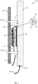
- FIG. 1 shows a side view of a cellular antenna assembly 100 according to one embodiment of the disclosure
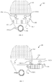
- FIG. 2 shows a top view of cellular antenna assembly 100
- Antenna assembly 100 comprises a radome 102, an active electronics module 110, a pipe 104, a pair of brackets 106(1) and 106(2), and optionally, a pair of sheaths 108 and 112.
- Radome 102 which houses (and generally protects from the elements) a plurality of antenna arrays (not shown), is attached to pipe 104 using brackets 106(1) and 106(2).
- bracket 106(1) is shown as a two-part clamp, having first part 130(1) and second part 130(2), which together clamp around pipe 104; however, numerous other types of brackets may be employed.
- antenna assembly 100 is installed by sliding pipe 104 over a mating pole or pipe (not shown) on a cell tower, such that the mating pole or pipe (not shown) rests inside pipe 104.
- the term "cell tower” is used to refer to an elevated structure on which a cellular antenna is mounted, including, but not limited to, actual towers, tops of buildings, water towers, and high-tension towers.
- the term “cell-tower mounting structure” refers to the structure used to mount the antenna assembly to the tower.
- the cell-tower mounting structure is formed by brackets 106(1) and 106(2) and pipe 104; however, according to alternative embodiments, other cell-tower mounting structure may be used.
- Active electronics module 110 comprises electronics that process signals provided to, and received from, at least one of the antenna arrays in radome 102.
- active electronics refers to electronics that purposefully modifies at least one of (i) uplink signals received from an antenna array and (ii) downlink signals radiated by an antenna array. Active electronics are distinguished from passive electronics, such as antenna elements, which might or might not incidentally modify the uplink and/or downlink signals.
- electronics module 110 comprises an outer weatherproof housing that protects the electronics contained therein from the elements. As will be described below, electronics module 110 is (i) physically removeably connected to an outer surface 120 of radome 102 and (ii) electrically removeably connected to at least one of the antenna arrays within radome 102.
- electronics module 110 may be safely removed from antenna assembly 100 (i) while antenna assembly 100 is installed on a tower and, depending on the particular electrical configuration, (ii) without disturbing service to all of the antenna arrays in radome 102.
- Antenna assembly 100 can be shipped from a factory to the installation site as one unit, ready for installation on the cell tower, or as separate parts that are attached together to form antenna assembly 100 at the installation site by an installer.
- FIG. 4 shows a simplified schematic block diagram of antenna assembly 100 according to one embodiment of the disclosure.
- antenna assembly 100 is a dual-band antenna assembly comprising first and second antenna arrays 132 and 134 housed within radome 102.
- First antenna array 132 serves a high-frequency band (e.g., 1710 MHz to 2155 MHz) and second antenna array 134 serves a low-frequency band (e.g., 698 MHz to 896 MHz).
- Each antenna array has antenna elements for communicating in a dual-polarized mode, wherein half of the antenna elements in the array transmit and receive using a first polarization (e.g., +45°) and the remaining half of the antenna elements in the array transmit and receive using a second polarization (e.g., -45°).
- first and second antenna arrays 132 and 134 are merely passive devices that radiate and receive signals, without actively modifying the signals.
- First antenna array 132 is served by active electronics module 110, the housing of which, as described above, is physically removeably connected to radome 102.
- Electronics module 110 is also electrically removeably connected to first antenna array 132 via RF connectors 128(1) and 128(2) of electronics module 110 and RF cables 138(1) and 138(2). Further, electronics module 110 is electrically connected to equipment at the base of the cell tower (not shown) via optical cable 114, which is removeably connected to optical connector 136 of radome 102.
- RF cables 138(1) and 138(2) and RF connectors 128(1) and 128(2) may be protected from the elements (i.e., weatherproofed) using sheath 108 shown in FIG. 1 .
- optical connector 136 and the portion of optical cable 114 that connects to optical connector 136 may be protected from the elements using sheath 112 shown in FIG. 1 .
- Sheaths 108 and 112 are configured to slide out of the way to allow access for connecting and disconnecting the respective cables at connectors 128(1), 128(2), and 136.
- electronics module 110 receives a baseband downlink communications signal via cable 114 and prepares the baseband signal for transmission.
- electronics module 110 generates a pair of dual-polarized transmission signals (i.e., TX1 and TX2) from the baseband signal using processing such as, but not limited to, optical-to-electrical conversion, digital-to-analog conversion (DAC), up-conversion to the radio frequency, and power-amplification (PA).
- the dual-polarized downlink signals TX1 and TX2 are provided to first antenna array 132 via RF cables 138(1) and 138(2), respectively.
- electronics module 110 receives dual-polarized uplink signals RX1 and RX2 from first antenna array 132 via RF cables 138(1) and 138(2), respectively.
- Electronics module 110 performs processing to generate a single baseband signal that is provided to the base-station below (not shown) via optical cable 114.
- electronics module 110 generates the baseband signal using processing such as, but not limited to, low-noise amplification (LNA), frequency down-conversion, analog-to-digital conversion (ADC), combining of the dual-polarized signals, and electrical-to-optical conversion.
- LNA low-noise amplification
- ADC analog-to-digital conversion
- Second antenna array 134 is served by a second electronics module (not shown) that is installed on the ground at the base station.
- the second electronics module (not shown) performs operations similar to those of electronics module 110 to (i) generate dual-polarized signals for transmission by second antenna array 134 in the downlink direction and (ii) generate a combined base-band signal from a pair of dual-polarized signals received by second antenna array 134 in the uplink direction.
- the dual-polarized signals are transferred between second antenna array 134 and the second electronics module using a pair of RF cables 116(1) and 116(2) (only one of which is shown in FIG. 1 ), which are removeably connected to RF connectors 118(1) and 118(2) of radome 102, respectively.
- FIG. 3 shows a top view of antenna assembly 100 with electronics module 110 partially removed. Note that, for ease of illustration, sheath 108 and RF cables 138(1) and 138(2) are not shown. To remove electronics module 110, RF cables 138(1) and 138(2) are disconnected from RF connectors 128(1) and 128(2). Electronics module 110 is then removed from radome 102 by sliding electronics module 110 out from between radome 102 and pipe 104 in a direction that is perpendicular to the axis of pipe 104 (i.e., out the side). Note that this operation can be performed by a single worker, while radome 102 remains installed on the cell tower, without disrupting service to second antenna array 134.
- Electronics module 110 is removeably connected to radome 102 using electronics module mounting structure.
- the electronics module mounting structure on radome 102 is formed by fastener 126, which is attached to radome 102
- the electronics module mounting structure on electronics module 110 is formed by fastener 124, which is attached to electronics module 110.
- fastener 126 is a protrusion extending across the width of radome 102 having a T-shaped cross-section
- fastener 124 is a channel protruding across the width of electronics module 110 having a cutout with a T-shaped cross-section for receiving fastener 126.
- electronics module 110 and radome 102 may be removeably connected using other types of mounting structures, including other types of fasteners. It is preferred, but not required, that such other types of fasteners provide a quick release and permit electronics module 110 and radome 102 to be mated to one another blindly. Further, the fasteners can be standardized such that installers can selectively and independently configure (and, if appropriate, re-configure) each different antenna array either as an active antenna with a corresponding electronics module behind the radome or as a passive antenna with its electronics module located at the base of the cell tower.
- second antenna array 134 can continue to operate as electronics module 110 is removed and possibly replaced with another electronics module (installed with radome 102 or at the base station on the ground).
- FIG. 5 shows a side view of antenna assembly 100 without electronics module 110 installed.
- first antenna array 132 can also be served by an electronics module (not shown) that is located at the base of the cell tower by connecting RF cables 140(1) and 140(2) (only one of which is shown in FIG. 5 ) to cables 138(1) and 138(2), respectively.
- the electronics module at the base of the cell tower may be electronics module 110 or another electronics module designed for installation at the base of the cell tower.
- antenna assembly 100 is merely a passive antenna device that radiates and receives signals without actively modifying the signals.
- antenna assemblies of the disclosure may serve as few as one frequency band or more than two frequency bands.
- one electronics module may serve the frequency band or two or more modules may serve the same frequency band.
- antenna assemblies of the disclosure may serve frequency bands other than the exemplary frequency bands described above.
- antenna assemblies of the disclosure may support a single polarization or more than two polarizations of a signal to be communicated.
- antenna assemblies of the disclosure may implement more than one electronics module that is removably connected to the radome, and electronics modules that are removable towards the top or bottom of the radome.
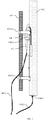
- FIG. 6 shows a side view of a cellular antenna assembly 600 in which an electronics module 604 is removable towards the top of the radome 602. Note that, to accommodate removal towards the top of radome 602, fasteners other than fasteners 124 and 126 may be used.
- antenna assemblies of the disclosure may support multi-mode communications, wherein the antenna arrays support two or more different radio-access technologies.
- electronics module 110 was described as being removeably attached to radome 102, embodiments of the disclosure are not so limited. According to alternative embodiments, electronics modules of the disclosure may be removeably attached to another surface between the cell-tower mounting structure and the radome. For example, electronics modules of the disclosure may be removeably attached to brackets 106(1) and 106(2) and/or pipe 104.
- primary and backup electronics modules may be removeably attached between the cell-tower mounting structure and the radome.
- the primary electronics module may serve one or more antenna arrays behind the radome. If and when the primary electronics module fails, the backup electronics module may supply service to the one or more antenna arrays.
- Couple refers to any manner known in the art or later developed in which energy is allowed to be transferred between two or more elements, and the interposition of one or more additional elements is contemplated, although not required. Conversely, the terms “directly coupled,” “directly connected,” etc., imply the absence of such additional elements.
Landscapes
- Engineering & Computer Science (AREA)
- Computer Networks & Wireless Communication (AREA)
- Details Of Aerials (AREA)
Claims (14)
- Vorrichtung (100), umfassend ein Radom (102) und ein aktives Elektronikmodul (110), wobei:das Radom (102) konfiguriert ist, um eine Befestigung von mindestens einer Antennenanordnung (132 oder 134) hinter dem Radom (102) zu unterstützen;das aktive Elektronikmodul (110) einen oder mehrere Hochfrequenz, HF, Verbinder (128(1), 128(2)) umfasst, wobei das aktive Elektronikmodul (110) physikalisch entnehmbar mit einer Außenfläche des Radoms verbunden ist und elektrisch trennbar mit der mindestens einen Antennenanordnung innerhalb des Radoms über ein oder mehrere HF-Kabel (138(1), 138(2)) verbunden ist, die mit dem einen oder mehreren HF-Verbindern (128(1), 128(2)) verbunden sind, und wobei das aktive Elektronikmodul (110) konfiguriert ist, um mindestens eines von (i) Abwärtsstrecke-Signale, die von der mindestens einen Antennenanordnung (132 oder 134) gesendet werden, und (ii) Aufwärtsstrecke-Signale, die von der mindestens einen Antennenanordnung (132 oder 134) empfangen werden, zu verarbeiten,die Vorrichtung (100) ferner eine Elektronikmodul-Befestigungsstruktur umfasst, die ein erstes wiederverwendbares Befestigungselement (124) umfasst, das konfiguriert ist, um ein zweites wiederverwendbares Befestigungselement (126) aufzunehmen, das mit dem Radom (102) gekoppelt ist,dadurch gekennzeichnet, dass:
das erste und zweite wiederverwendbare Befestigungselement konfiguriert sind, um die entnehmbare Befestigung des aktiven Elektronikmoduls (110) hinter dem Radom (102) derart zu unterstützen, dass, wenn das Radom (102) an einem Funkmast befestigt ist, wobei das aktive Elektronikmodul (110) entnehmbar hinter dem Radom (102) befestigt ist, dann das aktive Elektronikmodul (110) hinter dem Radom (102) entfernt werden kann, indem das aktive Elektronikmodul (110) in einer Richtung senkrecht zur Längsachse des Radoms verschoben wird, ohne dass das Radom (102) vom Funkmast entnommen wird. - Vorrichtung (100) nach Anspruch 1, wobei:
das zweite wiederverwendbare Befestigungselement (126) zur Befestigung an der Elektronikmodul-Befestigungsstruktur positioniert ist. - Vorrichtung (100) nach Anspruch 1, wobei:
das aktive Elektronikmodul (110) verschiebbar hinter dem Radom (102) befestigt ist. - Vorrichtung (100) nach Anspruch 2, wobei:das erste wiederverwendbare Befestigungselement (124) ein länglicher Vorsprung ist und das zweite wiederverwendbare Befestigungselement (126) ein komplementärer Kanal ist; undder Kanal dazu konfiguriert ist, um den länglichen Vorsprung aufzunehmen.
- Vorrichtung (100) nach Anspruch 1, wobei:die mindestens eine Antennenanordnung (132 oder 134) hinter dem Radom (102) befestigt ist; unddas aktive Elektronikmodul (110) hinter dem Radom (102) entnehmbar ist, ohne dass die mindestens eine Antennenanordnung (132 oder 134) einer Umgebung außerhalb des Radoms (102) ausgesetzt wird.
- Vorrichtung (100) nach Anspruch 5, wobei das aktive Elektronikmodul (110) umfasst:eine Schaltung, die konfiguriert ist, um mindestens eines von (i) den Abwärtsstrecke-Signale, und (ii) den Aufwärtsstrecke-Signale zu verarbeiten; undein Gehäuse, welches vom Radom (102) getrennt ist, welches zur Aufnahme der Schaltung konfiguriert ist.
- Vorrichtung (100) nach Anspruch 6, wobei:das Gehäuse wetterfest ist; unddas aktive Elektronikmodul (110) dazu konfiguriert ist, um hinter dem Radom (102) entnommen zu werden, ohne dass die Schaltung einer Umgebung außerhalb des Gehäuses ausgesetzt wird.
- Vorrichtung (100) nach Anspruch 1, wobei:die Vorrichtung (100) ferner mindestens eine zweite Antennenanordnung (134) umfasst, die hinter dem Radom (102) befestigt ist;das aktive Elektronikmodul (110) dazu konfiguriert ist, um mindestens eines von (i) Abwärtsstrecke-Signale, die von der ersten Antennenanordnung (132) gesendeten werden, und (ii) Aufwärtsstrecke-Signale, die von der ersten Antennenanordnung (132) empfangen werden, zu verarbeiten; unddas aktive Elektronikmodul (110) dazu konfiguriert ist, um von der Vorrichtung (100) entnommen zu werden, ohne dass Signale, die an die oder von der zweiten Antennenanordnung (134) übertragen werden, gestört werden.
- Vorrichtung (100) nach Anspruch 8, wobei:die Vorrichtung (100) ferner mindestens ein weiteres aktives Elektronikmodul (110) umfasst,das mindestens eine weitere aktive Elektronikmodul (110) dazu konfiguriert ist, um mindestens eines von (i) Abwärtsstrecke-Signale, die von der zweiten Antennenanordnung (134) gesendeten werden, und (ii) Aufwärtsstrecke-Signale, die von der zweiten Antennenanordnung (134) empfangen werden, zu verarbeiten;das mindestens eine weitere aktive Elektronikmodul (110) hinter dem Radom (102) befestigt ist; unddas aktive Elektronikmodul (110) dazu konfiguriert ist, um von der Vorrichtung (100) entnommen zu werden, ohne dass Signale, die von dem mindestens einen weiteren aktiven Elektronikmodul (110) an die zweite Antennenanordnung (134) übertragen werden, gestört werden.
- Vorrichtung (100) nach Anspruch 8, wobei:die zweite Antennenanordnung (134) von mindestens einem Basisstation-Elektronikmodul bedient wird, das konfiguriert ist, um mindestens eines von (i) Abwärtsstrecke-Signale, die von der zweiten Antennenanordnung (134) gesendeten werden, und (ii) Aufwärtsstrecke-Signale, die von der zweiten Antennenanordnung (134) empfangen werden, zu verarbeiten;das mindestens eine Basisstation-Elektronikmodul an einer Basis des Funkmastes installiert ist; unddas aktive Elektronikmodul (110) dazu konfiguriert ist, um hinter dem Radom (102) entnommen zu werden, ohne einen Dienst zu stören, der durch das mindestens eine Basisstation-Elektronikmodul an die zweite Antennenanordnung (134) übertragen wird.
- Vorrichtung (100) nach Anspruch 1, wobei:die Vorrichtung (100) auf dem Funkmast installiert ist; unddie mindestens eine Antennenanordnung (132 oder 134) von einem Basisstation-Elektronikmodul bedient wird, das an einer Basis des Funkmastes installiert ist.
- Vorrichtung (100) nach Anspruch 1, wobei die Vorrichtung (100) eine Funkmast-Befestigungsstruktur enthält, welche umfasst:ein Rohr (104); undmindestens eine Klammer (106(1), 106(2)), die dazu konfiguriert ist, um das Radom (102) an dem Rohr (104) zu befestigen.
- Vorrichtung (100) nach Anspruch 1, wobei:die Vorrichtung (100) eine zweite Antennenanordnung (134) umfasst;das aktive Elektronikmodul (110) dazu konfiguriert ist, um mindestens eines von (i) Abwärtsstrecke-Signale, die von der ersten Antennenanordnung (132) gesendeten werden, und (ii) Aufwärtsstrecke-Signale, die von der ersten Antennenanordnung (132) empfangen werden, zu verarbeiten; unddas aktive Elektronikmodul (110) umfasst:eine Schaltung, die konfiguriert dazu ist, um mindestens eines von (i) die Abwärtsstrecke-Signale, und (ii) die Aufwärtsstrecke-Signale zu verarbeiten; undein Gehäuse, welches von dem Radom (102) getrennt ist, welches dazu konfiguriert ist, um die Schaltung aufzunehmen, wobei:das Gehäuse des aktiven Elektronikmoduls (110) unter Verwendung der Elektronikmodul-Befestigungsstruktur entnehmbar am Radom (102) befestigt ist; unddas aktive Elektronikmodul (110) dazu konfiguriert ist, um hinter dem Radom (102) entnommen zu werden, ohne dass Dienstsignale an die oder von der zweiten Antennenanordnung (134) gestört werden.
- Vorrichtung (100) nach Anspruch 1, wobei:die Vorrichtung (100) eine Radomseite aufweist, an der das Radom (102) befestigt ist; unddie Vorrichtung (100) dazu konfiguriert ist, um einen Zugang zum aktiven Elektronikmodul (110) von einer Seite, die sich von der Radomseite unterscheidet, zu ermöglichen, so dass das aktive Elektronikmodul (110) entnommen werden kann, ohne dass die Radomseite gestört wird.
Applications Claiming Priority (2)
| Application Number | Priority Date | Filing Date | Title |
|---|---|---|---|
| US201261663318P | 2012-06-22 | 2012-06-22 | |
| PCT/US2013/036949 WO2013191800A1 (en) | 2012-06-22 | 2013-04-17 | Antenna radome with removeably connected electronics module |
Publications (2)
| Publication Number | Publication Date |
|---|---|
| EP2865049A1 EP2865049A1 (de) | 2015-04-29 |
| EP2865049B1 true EP2865049B1 (de) | 2020-06-03 |
Family
ID=48237276
Family Applications (1)
| Application Number | Title | Priority Date | Filing Date |
|---|---|---|---|
| EP13720186.9A Active EP2865049B1 (de) | 2012-06-22 | 2013-04-17 | Antennenradom mit lösbar angeschlossenen elektronikmodulen |
Country Status (5)
| Country | Link |
|---|---|
| US (2) | US9325061B2 (de) |
| EP (1) | EP2865049B1 (de) |
| CN (1) | CN104508906A (de) |
| IN (1) | IN2014MN02586A (de) |
| WO (1) | WO2013191800A1 (de) |
Families Citing this family (20)
| Publication number | Priority date | Publication date | Assignee | Title |
|---|---|---|---|---|
| US9325061B2 (en) * | 2012-06-22 | 2016-04-26 | Commscope Technologies Llc | Antenna radome with removeably connected electronics module |
| KR102140293B1 (ko) * | 2014-02-24 | 2020-08-11 | 주식회사 케이엠더블유 | 멀티 밴드 안테나 장치 |
| US9954568B1 (en) | 2014-06-25 | 2018-04-24 | Sprint Communications Company L.P. | Antenna module communication control in an antenna enclosure system |
| WO2016036951A1 (en) * | 2014-09-04 | 2016-03-10 | Commscope Technologies Llc | Azimuth and elevation angle pole mounting system for wireless communications base sites |
| US9888391B2 (en) * | 2014-10-23 | 2018-02-06 | Amphenol Antenna Solutions, Inc. | Ultra-wideband active antenna platform |
| KR102376170B1 (ko) * | 2014-11-04 | 2022-03-21 | 주식회사 케이엠더블유 | 안테나 장치 |
| CN106532243A (zh) * | 2015-09-14 | 2017-03-22 | 莱尔德电子材料(上海)有限公司 | 车载天线组件、组装车载天线组件的方法和系统 |
| WO2018022307A1 (en) | 2016-07-25 | 2018-02-01 | Commscope Technologies Llc | Integrated cell site sector |
| GB2579977B8 (en) * | 2017-08-15 | 2023-07-19 | Commscope Design & Integration Uk Ltd | Antenna mounting bracket assembly |
| EP3565057B1 (de) | 2018-05-02 | 2020-04-22 | Xilinx, Inc. | Antennensystem, kommunikationssystem, verfahren |
| EP3573179B1 (de) * | 2018-05-24 | 2023-09-20 | Nokia Shanghai Bell Co., Ltd. | Antennensystem |
| WO2020060819A1 (en) * | 2018-09-20 | 2020-03-26 | Commscope Technologies Llc | Metrocell antennas configured for mounting around utility poles |
| WO2020072880A1 (en) | 2018-10-05 | 2020-04-09 | Commscope Technologies Llc | Reconfigurable multi-band base station antennas having self-contained sub-modules |
| US20200227837A1 (en) * | 2019-01-15 | 2020-07-16 | Nokia Technologies Oy | Reconfigurable hybrid antenna for wireless communication networks |
| EP3869612A1 (de) * | 2020-02-24 | 2021-08-25 | CommScope Technologies LLC | Konnektivität und feldaustauschbarkeit von auf basisstationsantennen montierten funkgeräten |
| US11289798B2 (en) | 2020-02-24 | 2022-03-29 | Commscope Technologies Llc | Connectivity and field replaceability of radios mounted on base station antennas |
| US11522279B1 (en) | 2020-06-05 | 2022-12-06 | Xilinx, Inc. | Radome with integrated antenna array and antenna assembly having the same |
| CN111564689A (zh) * | 2020-06-29 | 2020-08-21 | 京信通信技术(广州)有限公司 | 一种天线安装组件和基站天线 |
| CN116154451A (zh) * | 2021-11-19 | 2023-05-23 | 康普技术有限责任公司 | 用于集成式基站天线的安装组件和集成式基站天线 |
| WO2024039441A1 (en) * | 2022-08-19 | 2024-02-22 | Commscope Technologies Llc | Base station antennas having an active antenna module(s) and related mounting systems and methods |
Citations (1)
| Publication number | Priority date | Publication date | Assignee | Title |
|---|---|---|---|---|
| CN201233948Y (zh) * | 2008-07-10 | 2009-05-06 | 中国移动通信集团公司 | 一种天线子系统、天线单元和射频拉远单元 |
Family Cites Families (10)
| Publication number | Priority date | Publication date | Assignee | Title |
|---|---|---|---|---|
| US7671801B2 (en) * | 2005-09-19 | 2010-03-02 | Raytheon Company | Armor for an electronically scanned array |
| US7394439B1 (en) * | 2006-06-19 | 2008-07-01 | Sprintcommunications Company L.P. | Multi-link antenna array that conforms to cellular leasing agreements for only one attachment fee |
| US7642988B1 (en) * | 2006-06-19 | 2010-01-05 | Sprint Communications Company L.P. | Multi-link antenna array configured for cellular site placement |
| US7881752B1 (en) * | 2006-06-19 | 2011-02-01 | Sprint Communications Company L.P. | Hybrid architecture that combines a metropolitan-area network fiber system with a multi-link antenna array |
| US7642961B1 (en) * | 2006-12-19 | 2010-01-05 | Sprint Communications Company L.P. | Remote control antenna positioning system |
| US8063837B1 (en) * | 2008-09-23 | 2011-11-22 | Rockwell Collins, Inc. | System for providing a pressure vessel, radome, RF sub-system box and electrically small, wideband omni and/or adaptable beam antenna |
| DE202009001821U1 (de) * | 2009-02-12 | 2009-04-16 | Kathrein-Werke Kg | Antenne, insbesondere Mobilfunkantenne |
| CN102308437B (zh) | 2009-05-26 | 2013-09-11 | 华为技术有限公司 | 一种天线装置 |
| CN102696150B (zh) * | 2009-12-02 | 2014-10-01 | 安德鲁有限责任公司 | 具有密封的无线电外壳的平板天线 |
| US9325061B2 (en) * | 2012-06-22 | 2016-04-26 | Commscope Technologies Llc | Antenna radome with removeably connected electronics module |
-
2013
- 2013-04-17 US US14/239,813 patent/US9325061B2/en active Active
- 2013-04-17 CN CN201380039525.XA patent/CN104508906A/zh active Pending
- 2013-04-17 WO PCT/US2013/036949 patent/WO2013191800A1/en active Application Filing
- 2013-04-17 EP EP13720186.9A patent/EP2865049B1/de active Active
- 2013-04-17 IN IN2586MUN2014 patent/IN2014MN02586A/en unknown
-
2016
- 2016-04-25 US US15/137,331 patent/US9692115B2/en active Active
Patent Citations (1)
| Publication number | Priority date | Publication date | Assignee | Title |
|---|---|---|---|---|
| CN201233948Y (zh) * | 2008-07-10 | 2009-05-06 | 中国移动通信集团公司 | 一种天线子系统、天线单元和射频拉远单元 |
Also Published As
| Publication number | Publication date |
|---|---|
| IN2014MN02586A (de) | 2015-09-11 |
| US9692115B2 (en) | 2017-06-27 |
| EP2865049A1 (de) | 2015-04-29 |
| US20150091777A1 (en) | 2015-04-02 |
| US9325061B2 (en) | 2016-04-26 |
| WO2013191800A1 (en) | 2013-12-27 |
| US20160240916A1 (en) | 2016-08-18 |
| CN104508906A (zh) | 2015-04-08 |
Similar Documents
| Publication | Publication Date | Title |
|---|---|---|
| US9692115B2 (en) | Antenna radome with removeably connected electronics module | |
| US8457700B2 (en) | GPS mast module and mobile radio installation | |
| US20180139708A1 (en) | Integrated wireless access devices for providing access to cellular and wireless local area networks | |
| CN102696150A (zh) | 具有密封的无线电外壳的平板天线 | |
| CN102369635B (zh) | 具有密封无线电设备外壳的平板天线 | |
| KR20000075941A (ko) | 셀룰라 통신 시스템 | |
| US20160099745A1 (en) | Integrated antenna unit with field replaceable frequency specific devices | |
| US11637619B2 (en) | Radio frequency signal boosters serving as outdoor infrastructure in high frequency cellular networks | |
| US20190140733A1 (en) | Radio frequency signal boosters for high frequency cellular communications | |
| EP3883054B1 (de) | Basisstations-antenneneinheiten mit arrays, die mehrere antennen überspannen, die durch überbrückungskabel verbunden sind | |
| US10585460B2 (en) | Pole integrated repeater system | |
| EP3570444A1 (de) | Faserintegriertes funkgerät für netzwerkoptimierungs- und verdichtungsökosystem (brandknoten) | |
| WO2018231283A1 (en) | Base station antennas having bottom end caps with angled connector ports | |
| US11979218B1 (en) | Radio frequency signal boosters serving as outdoor infrastructure in high frequency cellular networks | |
| KR20010001091A (ko) | 마스트 안테나 시스템 | |
| WO2024104027A1 (zh) | 一种天线及基站 | |
| KR20150133246A (ko) | 다중 대역 능동 안테나 | |
| WO2002065577A2 (en) | Antenna packaging and mounting assemblies and method | |
| KR102007122B1 (ko) | 화재감시 기능을 갖는 평판형 안테나 장치 | |
| KR20080102822A (ko) | 전송 및 이동통신용 마이크로웨이브 장치 | |
| WO2021087957A1 (en) | Metrocell antenna assemblies and utility pole assemblies and base stations including same | |
| KR101117500B1 (ko) | 마이크로웨이브를 이용한 다중섹터 이동통신 안테나 중계시스템 | |
| CN118073815A (en) | Antenna and base station | |
| KR20160104495A (ko) | 통합형 안테나 시스템 | |
| KR20030033824A (ko) | 이동통신 기지국의 원격감시 및 rf 분산 시스템 |
Legal Events
| Date | Code | Title | Description |
|---|---|---|---|
| PUAI | Public reference made under article 153(3) epc to a published international application that has entered the european phase |
Free format text: ORIGINAL CODE: 0009012 |
|
| 17P | Request for examination filed |
Effective date: 20140326 |
|
| AK | Designated contracting states |
Kind code of ref document: A1 Designated state(s): AL AT BE BG CH CY CZ DE DK EE ES FI FR GB GR HR HU IE IS IT LI LT LU LV MC MK MT NL NO PL PT RO RS SE SI SK SM TR |
|
| AX | Request for extension of the european patent |
Extension state: BA ME |
|
| RAP1 | Party data changed (applicant data changed or rights of an application transferred) |
Owner name: COMMSCOPE TECHNOLOGIES LLC |
|
| RIN1 | Information on inventor provided before grant (corrected) |
Inventor name: BUONDELMONTE, CHARLES, J. Inventor name: RUCKI, JOHN, S. Inventor name: COLAPIETRO, JULIAN, R. Inventor name: CHANDRASEKARAN, RAJIV |
|
| DAX | Request for extension of the european patent (deleted) | ||
| STAA | Information on the status of an ep patent application or granted ep patent |
Free format text: STATUS: EXAMINATION IS IN PROGRESS |
|
| 17Q | First examination report despatched |
Effective date: 20181018 |
|
| GRAP | Despatch of communication of intention to grant a patent |
Free format text: ORIGINAL CODE: EPIDOSNIGR1 |
|
| STAA | Information on the status of an ep patent application or granted ep patent |
Free format text: STATUS: GRANT OF PATENT IS INTENDED |
|
| INTG | Intention to grant announced |
Effective date: 20200114 |
|
| GRAS | Grant fee paid |
Free format text: ORIGINAL CODE: EPIDOSNIGR3 |
|
| GRAA | (expected) grant |
Free format text: ORIGINAL CODE: 0009210 |
|
| STAA | Information on the status of an ep patent application or granted ep patent |
Free format text: STATUS: THE PATENT HAS BEEN GRANTED |
|
| AK | Designated contracting states |
Kind code of ref document: B1 Designated state(s): AL AT BE BG CH CY CZ DE DK EE ES FI FR GB GR HR HU IE IS IT LI LT LU LV MC MK MT NL NO PL PT RO RS SE SI SK SM TR |
|
| REG | Reference to a national code |
Ref country code: GB Ref legal event code: FG4D |
|
| REG | Reference to a national code |
Ref country code: CH Ref legal event code: EP Ref country code: AT Ref legal event code: REF Ref document number: 1277988 Country of ref document: AT Kind code of ref document: T Effective date: 20200615 |
|
| REG | Reference to a national code |
Ref country code: DE Ref legal event code: R096 Ref document number: 602013069599 Country of ref document: DE |
|
| REG | Reference to a national code |
Ref country code: LT Ref legal event code: MG4D |
|
| PG25 | Lapsed in a contracting state [announced via postgrant information from national office to epo] |
Ref country code: GR Free format text: LAPSE BECAUSE OF FAILURE TO SUBMIT A TRANSLATION OF THE DESCRIPTION OR TO PAY THE FEE WITHIN THE PRESCRIBED TIME-LIMIT Effective date: 20200904 Ref country code: NO Free format text: LAPSE BECAUSE OF FAILURE TO SUBMIT A TRANSLATION OF THE DESCRIPTION OR TO PAY THE FEE WITHIN THE PRESCRIBED TIME-LIMIT Effective date: 20200903 Ref country code: SE Free format text: LAPSE BECAUSE OF FAILURE TO SUBMIT A TRANSLATION OF THE DESCRIPTION OR TO PAY THE FEE WITHIN THE PRESCRIBED TIME-LIMIT Effective date: 20200603 Ref country code: FI Free format text: LAPSE BECAUSE OF FAILURE TO SUBMIT A TRANSLATION OF THE DESCRIPTION OR TO PAY THE FEE WITHIN THE PRESCRIBED TIME-LIMIT Effective date: 20200603 Ref country code: LT Free format text: LAPSE BECAUSE OF FAILURE TO SUBMIT A TRANSLATION OF THE DESCRIPTION OR TO PAY THE FEE WITHIN THE PRESCRIBED TIME-LIMIT Effective date: 20200603 |
|
| REG | Reference to a national code |
Ref country code: NL Ref legal event code: MP Effective date: 20200603 |
|
| PG25 | Lapsed in a contracting state [announced via postgrant information from national office to epo] |
Ref country code: HR Free format text: LAPSE BECAUSE OF FAILURE TO SUBMIT A TRANSLATION OF THE DESCRIPTION OR TO PAY THE FEE WITHIN THE PRESCRIBED TIME-LIMIT Effective date: 20200603 Ref country code: LV Free format text: LAPSE BECAUSE OF FAILURE TO SUBMIT A TRANSLATION OF THE DESCRIPTION OR TO PAY THE FEE WITHIN THE PRESCRIBED TIME-LIMIT Effective date: 20200603 Ref country code: BG Free format text: LAPSE BECAUSE OF FAILURE TO SUBMIT A TRANSLATION OF THE DESCRIPTION OR TO PAY THE FEE WITHIN THE PRESCRIBED TIME-LIMIT Effective date: 20200903 Ref country code: RS Free format text: LAPSE BECAUSE OF FAILURE TO SUBMIT A TRANSLATION OF THE DESCRIPTION OR TO PAY THE FEE WITHIN THE PRESCRIBED TIME-LIMIT Effective date: 20200603 |
|
| REG | Reference to a national code |
Ref country code: AT Ref legal event code: MK05 Ref document number: 1277988 Country of ref document: AT Kind code of ref document: T Effective date: 20200603 |
|
| PG25 | Lapsed in a contracting state [announced via postgrant information from national office to epo] |
Ref country code: NL Free format text: LAPSE BECAUSE OF FAILURE TO SUBMIT A TRANSLATION OF THE DESCRIPTION OR TO PAY THE FEE WITHIN THE PRESCRIBED TIME-LIMIT Effective date: 20200603 Ref country code: AL Free format text: LAPSE BECAUSE OF FAILURE TO SUBMIT A TRANSLATION OF THE DESCRIPTION OR TO PAY THE FEE WITHIN THE PRESCRIBED TIME-LIMIT Effective date: 20200603 |
|
| PG25 | Lapsed in a contracting state [announced via postgrant information from national office to epo] |
Ref country code: ES Free format text: LAPSE BECAUSE OF FAILURE TO SUBMIT A TRANSLATION OF THE DESCRIPTION OR TO PAY THE FEE WITHIN THE PRESCRIBED TIME-LIMIT Effective date: 20200603 Ref country code: CZ Free format text: LAPSE BECAUSE OF FAILURE TO SUBMIT A TRANSLATION OF THE DESCRIPTION OR TO PAY THE FEE WITHIN THE PRESCRIBED TIME-LIMIT Effective date: 20200603 Ref country code: IT Free format text: LAPSE BECAUSE OF FAILURE TO SUBMIT A TRANSLATION OF THE DESCRIPTION OR TO PAY THE FEE WITHIN THE PRESCRIBED TIME-LIMIT Effective date: 20200603 Ref country code: PT Free format text: LAPSE BECAUSE OF FAILURE TO SUBMIT A TRANSLATION OF THE DESCRIPTION OR TO PAY THE FEE WITHIN THE PRESCRIBED TIME-LIMIT Effective date: 20201006 Ref country code: AT Free format text: LAPSE BECAUSE OF FAILURE TO SUBMIT A TRANSLATION OF THE DESCRIPTION OR TO PAY THE FEE WITHIN THE PRESCRIBED TIME-LIMIT Effective date: 20200603 Ref country code: EE Free format text: LAPSE BECAUSE OF FAILURE TO SUBMIT A TRANSLATION OF THE DESCRIPTION OR TO PAY THE FEE WITHIN THE PRESCRIBED TIME-LIMIT Effective date: 20200603 Ref country code: SM Free format text: LAPSE BECAUSE OF FAILURE TO SUBMIT A TRANSLATION OF THE DESCRIPTION OR TO PAY THE FEE WITHIN THE PRESCRIBED TIME-LIMIT Effective date: 20200603 Ref country code: RO Free format text: LAPSE BECAUSE OF FAILURE TO SUBMIT A TRANSLATION OF THE DESCRIPTION OR TO PAY THE FEE WITHIN THE PRESCRIBED TIME-LIMIT Effective date: 20200603 |
|
| PG25 | Lapsed in a contracting state [announced via postgrant information from national office to epo] |
Ref country code: SK Free format text: LAPSE BECAUSE OF FAILURE TO SUBMIT A TRANSLATION OF THE DESCRIPTION OR TO PAY THE FEE WITHIN THE PRESCRIBED TIME-LIMIT Effective date: 20200603 Ref country code: PL Free format text: LAPSE BECAUSE OF FAILURE TO SUBMIT A TRANSLATION OF THE DESCRIPTION OR TO PAY THE FEE WITHIN THE PRESCRIBED TIME-LIMIT Effective date: 20200603 Ref country code: IS Free format text: LAPSE BECAUSE OF FAILURE TO SUBMIT A TRANSLATION OF THE DESCRIPTION OR TO PAY THE FEE WITHIN THE PRESCRIBED TIME-LIMIT Effective date: 20201003 |
|
| REG | Reference to a national code |
Ref country code: DE Ref legal event code: R097 Ref document number: 602013069599 Country of ref document: DE |
|
| PLBE | No opposition filed within time limit |
Free format text: ORIGINAL CODE: 0009261 |
|
| STAA | Information on the status of an ep patent application or granted ep patent |
Free format text: STATUS: NO OPPOSITION FILED WITHIN TIME LIMIT |
|
| PG25 | Lapsed in a contracting state [announced via postgrant information from national office to epo] |
Ref country code: DK Free format text: LAPSE BECAUSE OF FAILURE TO SUBMIT A TRANSLATION OF THE DESCRIPTION OR TO PAY THE FEE WITHIN THE PRESCRIBED TIME-LIMIT Effective date: 20200603 |
|
| 26N | No opposition filed |
Effective date: 20210304 |
|
| PG25 | Lapsed in a contracting state [announced via postgrant information from national office to epo] |
Ref country code: SI Free format text: LAPSE BECAUSE OF FAILURE TO SUBMIT A TRANSLATION OF THE DESCRIPTION OR TO PAY THE FEE WITHIN THE PRESCRIBED TIME-LIMIT Effective date: 20200603 |
|
| PG25 | Lapsed in a contracting state [announced via postgrant information from national office to epo] |
Ref country code: MC Free format text: LAPSE BECAUSE OF FAILURE TO SUBMIT A TRANSLATION OF THE DESCRIPTION OR TO PAY THE FEE WITHIN THE PRESCRIBED TIME-LIMIT Effective date: 20200603 |
|
| PG25 | Lapsed in a contracting state [announced via postgrant information from national office to epo] |
Ref country code: LU Free format text: LAPSE BECAUSE OF NON-PAYMENT OF DUE FEES Effective date: 20210417 |
|
| REG | Reference to a national code |
Ref country code: BE Ref legal event code: MM Effective date: 20210430 |
|
| PG25 | Lapsed in a contracting state [announced via postgrant information from national office to epo] |
Ref country code: CH Free format text: LAPSE BECAUSE OF NON-PAYMENT OF DUE FEES Effective date: 20210430 Ref country code: LI Free format text: LAPSE BECAUSE OF NON-PAYMENT OF DUE FEES Effective date: 20210430 |
|
| PG25 | Lapsed in a contracting state [announced via postgrant information from national office to epo] |
Ref country code: IE Free format text: LAPSE BECAUSE OF NON-PAYMENT OF DUE FEES Effective date: 20210417 |
|
| PG25 | Lapsed in a contracting state [announced via postgrant information from national office to epo] |
Ref country code: IS Free format text: LAPSE BECAUSE OF FAILURE TO SUBMIT A TRANSLATION OF THE DESCRIPTION OR TO PAY THE FEE WITHIN THE PRESCRIBED TIME-LIMIT Effective date: 20201003 |
|
| PG25 | Lapsed in a contracting state [announced via postgrant information from national office to epo] |
Ref country code: BE Free format text: LAPSE BECAUSE OF NON-PAYMENT OF DUE FEES Effective date: 20210430 |
|
| PG25 | Lapsed in a contracting state [announced via postgrant information from national office to epo] |
Ref country code: HU Free format text: LAPSE BECAUSE OF FAILURE TO SUBMIT A TRANSLATION OF THE DESCRIPTION OR TO PAY THE FEE WITHIN THE PRESCRIBED TIME-LIMIT; INVALID AB INITIO Effective date: 20130417 |
|
| PG25 | Lapsed in a contracting state [announced via postgrant information from national office to epo] |
Ref country code: CY Free format text: LAPSE BECAUSE OF FAILURE TO SUBMIT A TRANSLATION OF THE DESCRIPTION OR TO PAY THE FEE WITHIN THE PRESCRIBED TIME-LIMIT Effective date: 20200603 |
|
| P01 | Opt-out of the competence of the unified patent court (upc) registered |
Effective date: 20230530 |
|
| PGFP | Annual fee paid to national office [announced via postgrant information from national office to epo] |
Ref country code: FR Payment date: 20230425 Year of fee payment: 11 Ref country code: DE Payment date: 20230427 Year of fee payment: 11 |
|
| PGFP | Annual fee paid to national office [announced via postgrant information from national office to epo] |
Ref country code: GB Payment date: 20230427 Year of fee payment: 11 |
|
| PG25 | Lapsed in a contracting state [announced via postgrant information from national office to epo] |
Ref country code: MK Free format text: LAPSE BECAUSE OF FAILURE TO SUBMIT A TRANSLATION OF THE DESCRIPTION OR TO PAY THE FEE WITHIN THE PRESCRIBED TIME-LIMIT Effective date: 20200603 |