EP2864633B1 - Ionenbeschleuniger - Google Patents
Ionenbeschleuniger Download PDFInfo
- Publication number
- EP2864633B1 EP2864633B1 EP13733414.0A EP13733414A EP2864633B1 EP 2864633 B1 EP2864633 B1 EP 2864633B1 EP 13733414 A EP13733414 A EP 13733414A EP 2864633 B1 EP2864633 B1 EP 2864633B1
- Authority
- EP
- European Patent Office
- Prior art keywords
- magnet
- ion
- magnetic arrangement
- accelerator according
- propellant
- Prior art date
- Legal status (The legal status is an assumption and is not a legal conclusion. Google has not performed a legal analysis and makes no representation as to the accuracy of the status listed.)
- Not-in-force
Links
- 150000002500 ions Chemical class 0.000 claims description 40
- 239000003380 propellant Substances 0.000 claims description 23
- 230000001419 dependent effect Effects 0.000 claims 1
- 230000005684 electric field Effects 0.000 description 5
- 238000010884 ion-beam technique Methods 0.000 description 4
- 238000005229 chemical vapour deposition Methods 0.000 description 2
- 238000010586 diagram Methods 0.000 description 2
- 230000005686 electrostatic field Effects 0.000 description 2
- 230000001133 acceleration Effects 0.000 description 1
- 230000000295 complement effect Effects 0.000 description 1
- 239000004020 conductor Substances 0.000 description 1
- 150000001879 copper Chemical class 0.000 description 1
- 229910052802 copper Inorganic materials 0.000 description 1
- 239000010949 copper Substances 0.000 description 1
- 230000000694 effects Effects 0.000 description 1
- 238000000752 ionisation method Methods 0.000 description 1
- 229910052756 noble gas Inorganic materials 0.000 description 1
- 239000000523 sample Substances 0.000 description 1
Images

Classifications
-
- F—MECHANICAL ENGINEERING; LIGHTING; HEATING; WEAPONS; BLASTING
- F03—MACHINES OR ENGINES FOR LIQUIDS; WIND, SPRING, OR WEIGHT MOTORS; PRODUCING MECHANICAL POWER OR A REACTIVE PROPULSIVE THRUST, NOT OTHERWISE PROVIDED FOR
- F03H—PRODUCING A REACTIVE PROPULSIVE THRUST, NOT OTHERWISE PROVIDED FOR
- F03H1/00—Using plasma to produce a reactive propulsive thrust
- F03H1/0037—Electrostatic ion thrusters
- F03H1/0062—Electrostatic ion thrusters grid-less with an applied magnetic field
- F03H1/0068—Electrostatic ion thrusters grid-less with an applied magnetic field with a central channel, e.g. end-Hall type
-
- H—ELECTRICITY
- H05—ELECTRIC TECHNIQUES NOT OTHERWISE PROVIDED FOR
- H05H—PLASMA TECHNIQUE; PRODUCTION OF ACCELERATED ELECTRICALLY-CHARGED PARTICLES OR OF NEUTRONS; PRODUCTION OR ACCELERATION OF NEUTRAL MOLECULAR OR ATOMIC BEAMS
- H05H5/00—Direct voltage accelerators; Accelerators using single pulses
- H05H5/02—Details
-
- F—MECHANICAL ENGINEERING; LIGHTING; HEATING; WEAPONS; BLASTING
- F03—MACHINES OR ENGINES FOR LIQUIDS; WIND, SPRING, OR WEIGHT MOTORS; PRODUCING MECHANICAL POWER OR A REACTIVE PROPULSIVE THRUST, NOT OTHERWISE PROVIDED FOR
- F03H—PRODUCING A REACTIVE PROPULSIVE THRUST, NOT OTHERWISE PROVIDED FOR
- F03H1/00—Using plasma to produce a reactive propulsive thrust
- F03H1/0037—Electrostatic ion thrusters
-
- H—ELECTRICITY
- H01—ELECTRIC ELEMENTS
- H01J—ELECTRIC DISCHARGE TUBES OR DISCHARGE LAMPS
- H01J27/00—Ion beam tubes
- H01J27/02—Ion sources; Ion guns
- H01J27/08—Ion sources; Ion guns using arc discharge
- H01J27/14—Other arc discharge ion sources using an applied magnetic field
- H01J27/146—End-Hall type ion sources, wherein the magnetic field confines the electrons in a central cylinder
-
- H—ELECTRICITY
- H01—ELECTRIC ELEMENTS
- H01J—ELECTRIC DISCHARGE TUBES OR DISCHARGE LAMPS
- H01J27/00—Ion beam tubes
- H01J27/02—Ion sources; Ion guns
- H01J27/20—Ion sources; Ion guns using particle beam bombardment, e.g. ionisers
- H01J27/205—Ion sources; Ion guns using particle beam bombardment, e.g. ionisers with electrons, e.g. electron impact ionisation, electron attachment
Definitions
- the present invention relates to ion accelerators. Its primary application is in plasma thrusters, for example for use in the control of space probes and satellites, but it also has application in chemical vapour deposition (CVD), in lighting systems that require a source of plasma.
- CVD chemical vapour deposition
- Plasma thrusters which comprise a plasma chamber with an anode and a cathode which set up an electric field in the chamber, the cathode acting as a source of electrons. Magnets provide regions of high magnetic field in the chamber.
- a propellant typically a noble gas, is introduced into the chamber. Electrons from the cathode are accelerated through the chamber, ionizing the propellant to form a plasma. Positive ions in the plasma are accelerated towards the cathode, which is at an open end of the chamber, while electrons are deflected and captured by the magnetic field, because of their higher charge/mass ratio.
- As more propellant is fed into the chamber the primary electrons from the cathode and the secondary electrons from the ionization process continue to ionize the propellant, projecting a continuous stream of ions from the open end of the thruster to produce thrust.
- multi-stage plasma thrusters are described in US2003/0048053 , and divergent cusped field (DCF) thrusters are also known.
- DCF divergent cusped field
- US 2010/107596 A1 discloses an ion accelerator according to the preamble of claim 1.
- the present invention provides an ion accelerator comprising a first magnet, which may be an inner magnet, and which may have a channel extending through it, for example in an axial direction, and second magnet, which may be an outer magnet, and may extend around the first magnet, the magnets having like polarities so as to produce a magnetic field having two locations of zero magnetic field strength. The locations are spaced apart in the axial direction.
- the accelerator further comprises an anode and a cathode, arranged to generate an electrical potential difference between the locations.
- the channel may have a central axis.
- the central axis may be an axis of rotational symmetry.
- One of the locations may be a line that extends around the central axis.
- One of the locations is a point.
- the location that is a point may be forward of the other so that ions will tend to converge when moving between the locations.
- One of the electrodes which may be the anode, may be located radially between the inner and outer magnets.
- This electrode may include a tubular portion which may have an inner diameter greater than the outer diameter of the inner magnet, and an outer diameter less than the inner diameter of the outer magnet.
- One of the electrodes, which may be the cathode may be located radially inside the inner magnet, and may be located on, or around, the central axis.
- the channel may have an inlet end and an outlet end. These ends may be at respective poles of the inner magnet.
- the outer magnet may extend around at least a part of the inner magnet, and may have an inlet end and an outlet end, which may be at respective poles of the outer magnet.
- the inlet ends of the two magnets may be of like polarity.
- the magnets may be of annular cross section.
- the accelerator may further comprise a housing which may be arranged to support either one or both of the magnets.
- the accelerator may further comprise a heat sink which may be thermally connected to any one or more of the inner and outer magnets and the housing.
- the present invention further provides an ion thruster comprising an accelerator according to the invention and a propellant source arranged to feed propellant into the accelerator.
- the propellant source may be arranged to feed propellant to the cathode.
- the propellant source may be arranged to feed propellant into a space between the inner and outer magnets.
- the accelerator may include any one or more features, in any combination, of any one or more of the embodiments of the present invention which will now be described by way of example only with reference to the accompanying drawings.
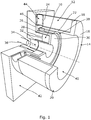
- a housing 14 supports the magnets 10, 12 and comprises an outer annular wall 16 which covers the annular end 18 of the outer magnet 12 at the front end 20 of the thruster, an outer cylindrical wall 22 which is just inside the outer magnet 12 and extends along its length beyond its rear end 24, a rear annular wall 26 extending inwards from the rear end of the outer cylindrical wall 22, a middle cylindrical wall 28 extending forwards from the inner edge of the rear annular wall 26 and extending along the outer surface of the inner magnet 10, an inner annular wall 30 extending inwards from the front end of the middle cylindrical wall 28, covering the front end of the inner magnet 10, and an inner cylindrical wall 32 extending rearwards from the inner edge of the inner annular wall along the inner surface of the inner magnet 10.
- the inner cylindrical wall 32 surrounds and defines within it a channel 34 which extends through the centre of the inner magnet 12, and a hollow cathode 36 is located at the rear end of the channel and arranged to generate plasma and introduce it into the channel 34.
- a tubular anode 38 is located in the space between the outer and middle cylindrical walls 22, 28, with its front end just forward of the front end of the inner magnet 10, and well behind the front end of the outer magnet 12.
- the anode, or the tubular portion of it has an inner diameter greater than the outer diameter of the inner magnet 10, and an outer diameter less than the inner diameter of the outer magnet 12.
- the cathode 36 and anode 38 are arranged to set up the electrostatic field required for the accelerator to operate as described below. In other embodiments the cathode for providing the electrostatic field can be separate from the plasma source.
- the rear ends of the two magnets 10, 12 are aligned with each other in the axial direction, and the outer magnet 12 is longer than the inner magnet 10 and extends forward of the front end of the inner magnet.
- the region inside the front end of the outer magnet 12 and forward of the inner magnet 10 forms a chamber 40 in which plasma generation and ion acceleration takes place as will be described in more detail below.
- the housing 14 shields the magnets 10, 12 from the channel 34 and plasma chamber 40.
- a heat sink 42 in this case in the form of a copper block, is located against, and in thermal contact with, the rear end of the housing 14 and the rear ends of the inner and outer magnets 10,12.
- the heat sink 42 has an aperture through which the hollow cathode 36 can be inserted and through which gas can be supplied to the hollow cathode 36.
- Four propellant channels 44 are provided extending radially through the heat sink 42 and connect to apertures 46 in the housing, in the rear end of the outer cylindrical wall 22. As the anode 38 is spaced from the outer and middle cylindrical walls 22, 28, propellant introduced into these propellant channels 44 can flow into the space between the outer and middle cylindrical walls 22, 28, and therefore between the inner and outer magnets 10, 12, past the anode 38, and into the main plasma chamber 40.
- the general principle of the accelerator is similar to known accelerators.
- the anode 38 and cathode 36 set up an electric field which accelerates electrons and ions in the plasma chamber 40.
- the accelerated electrons ionize the propellant introduced into the chamber 40 producing positive ions and further secondary electrons.
- the electrons because of their relatively high charge to mass ratio, are deflected by the magnetic field in the chamber and tend to follow the magnetic field, while the positive ions are relatively unaffected by the magnetic field and therefore tend to travel in a direction dictated by the electric field.
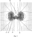
- the polarities of the inner and outer magnets 10, 12 are in the same direction. For example if the front end of the outer magnet 12 is its north pole and the rear end is its south pole, then the front end of the inner magnet 10 is also its north pole, and the rear end is its south pole.
- the polarities are therefore opposed to each other, and not complementary as they would be if the polarities were opposite to each other.
- This sets up a complex magnetic field having a point 50 of zero magnetic field located on the central axis of the accelerator and forward of the front end of the outer magnet 12, and a line 52 of zero magnetic field that is circular and extends around the central axis just forward of the front end of the inner magnet 10.
- a similar zero point and zero line 56 are set up to the rear of the magnets 10, 12 but these are not relevant to the operation of the accelerator.
- magnetic fields act as an electrical resistance to electrons trying to move perpendicular to them, as the electrons are deflected by the magnetic field, but lines which do not have significant magnetic field perpendicular to them have low electrical 'resistance' and therefore can be considered to act as 'conductors' as electrons can move relatively freely along them. Therefore it will be appreciated that the zero point 50 at the forward end of the accelerator is held at an electrical potential close to that of the cathode, because of the 'channel' of low transverse magnetic field between it and the cathode.
- the line 52 of zero magnetic field is held at a similar electrical potential to the anode, as there is little magnetic field transverse to the direction between them and a similar 'channel' of low transverse field can be seen between the front end of the anode 38 and the zero line 52, so electrons can move relatively freely between them.
- the positive ions are not significantly decelerated after passing the zero point 50 and form a continuous stream of ions ejected forwards from the front end of the accelerator. Meanwhile electrons gradually move towards the anode 38 and are collected there.
- propellant can be introduced into the plasma chamber 40 via the inlet channels 44 during operation of the accelerator to keep up a continuous beam of ions which produce thrust.
- propellant supply could of course also be used.
- the hollow cathode may be able to provide sufficient plasma and a separate supply of gas for ionisation may not be necessary.
- the hollow cathode is replaced by a simple cathode and the only supply of gas is via the inlet channels 44.
- the magnetic field forward of the zero point 50 is approximately parallel to the direction of travel of the ion beam. This helps to contain the ion beam as the positive ions tend to follow the magnetic field direction, though to a much lesser extent than the electrons due to the difference in charge to mass ratio.
- the geometry of the accelerator can be modified in many ways.
- the zero point 50 and zero line 52 at the front end of the accelerator are spaced apart in the axial (forward/backward) direction much more than those 54, 56 to the rear of the accelerator.
- the front ends of the inner and outer magnets 10, 12 are not level, in the axial direction, with the front end of the outer magnet 12 being forward of the front end of the inner magnet 10, whereas their rear ends are level in the axial direction.
- the relative lengths and axial positioning of the two magnets, and their relative size can be selected so as to achieve the axial spacing of the two regions of zero magnetic field and their relative size, suitable for a particular application.
- the inner and outer magnets can in some cases be of equal length. In some cases their front ends can be approximately level in the axial direction. However this means that the axial offset between the two zero field regions will be less than in the embodiment of Figure 1 .
- the positions of the inner and outer magnets 110, 112 is the same as that of the first embodiment, but the relative strengths is different, in this case the inner magnet being stronger than the outer magnet.
Landscapes
- Engineering & Computer Science (AREA)
- Chemical & Material Sciences (AREA)
- Combustion & Propulsion (AREA)
- Physics & Mathematics (AREA)
- Plasma & Fusion (AREA)
- Mechanical Engineering (AREA)
- General Engineering & Computer Science (AREA)
- High Energy & Nuclear Physics (AREA)
- Spectroscopy & Molecular Physics (AREA)
- Plasma Technology (AREA)
- Particle Accelerators (AREA)
Claims (13)
- Ionenbeschleuniger, der Folgendes umfasst: eine Magnetanordnung, die einen inneren Magneten, der einen Kanal aufweist, der sich durch ihn hindurch in eine axiale Richtung erstreckt, und einen äußeren Magneten, der sich um den inneren Magneten erstreckt, aufweist, wobei der innere und der äußere Magnet gleiche Polaritäten aufweisen, sodass die Magnetanordnung ein Magnetfeld erzeugt, das zwei Orte mit einer Magnetfeldstärke von Null aufweist, wobei die Orte in axialer Richtung beabstandet sind; und eine Anode und eine Kathode, die dazu angeordnet sind, einen Unterschied des elektrischen Potenzials zwischen den Orten zu erzeugen,
dadurch gekennzeichnet, dass einer der Orte ein Punkt ist. - Ionenbeschleuniger nach Anspruch 1, wobei der Kanal eine zentrale Achse aufweist und einer der Orte eine Linie ist, die sich um die zentrale Achse erstreckt.
- Ionenbeschleuniger nach Anspruch 1 oder Anspruch 2, wobei der Ort, der ein Punkt ist, vor dem anderen liegt, sodass Ionen dazu neigen, zusammenzuströmen, wenn sie sich zwischen den Orten bewegen.
- Ionenbeschleuniger nach einem der Ansprüche 1 bis 3, wobei der Punkt vor dem vorderen Ende des inneren Magneten der Magnetanordnung liegt.
- Ionenbeschleuniger nach einem der Ansprüche 1 bis 4, wobei der Punkt vor dem vorderen Ende des äußeren Magneten der Magnetanordnung liegt.
- Ionenbeschleuniger nach Anspruch 2 oder einem der Ansprüche 3 bis 5, wenn abhängig von Anspruch 2, wobei die Linie hinter dem vorderen Ende des äußeren Magneten der Magnetanordnung liegt.
- Ionenbeschleuniger nach einem der vorhergehenden Ansprüche, wobei eine der Elektroden radial zwischen dem inneren und dem äußeren Magneten der Magnetanordnung positioniert ist.
- Ionenbeschleuniger nach einem der vorhergehenden Ansprüche, wobei eine der Elektroden radial innerhalb des inneren Magneten der Magnetanordnung positioniert ist.
- Ionenbeschleuniger nach einem der vorhergehenden Ansprüche, wobei das vordere Ende des äußeren Magneten der Magnetanordnung vor dem vorderen Ende des inneren Magneten der Magnetanordnung liegt.
- Ionenbeschleuniger nach einem der vorhergehenden Ansprüche, wobei das vordere Ende des äußeren Magneten der Magnetanordnung vor dem vorderen Ende der Anode liegt.
- Ionentriebwerk, das einen Beschleuniger nach einem der vorhergehenden Ansprüche und eine Treibmittelquelle, die dazu angeordnet ist, dem Beschleuniger ein Treibmittel zuzuführen, umfasst.
- Ionentriebwerk nach Anspruch 11, wobei die Treibmittelquelle dazu angeordnet ist, der Kathode ein Treibmittel zuzuführen.
- Ionentriebwerk nach Anspruch 11 oder Anspruch 12, wobei die Treibmittelquelle dazu angeordnet ist, ein Treibmittel in einen Raum zwischen dem inneren und dem äußeren Magneten der Magnetanordnung einzuspeisen.
Applications Claiming Priority (2)
| Application Number | Priority Date | Filing Date | Title |
|---|---|---|---|
| GBGB1210994.8A GB201210994D0 (en) | 2012-06-21 | 2012-06-21 | Ion accelerators |
| PCT/GB2013/051586 WO2013190285A1 (en) | 2012-06-21 | 2013-06-18 | Ion accelerators |
Publications (2)
| Publication Number | Publication Date |
|---|---|
| EP2864633A1 EP2864633A1 (de) | 2015-04-29 |
| EP2864633B1 true EP2864633B1 (de) | 2019-03-13 |
Family
ID=46641271
Family Applications (1)
| Application Number | Title | Priority Date | Filing Date |
|---|---|---|---|
| EP13733414.0A Not-in-force EP2864633B1 (de) | 2012-06-21 | 2013-06-18 | Ionenbeschleuniger |
Country Status (7)
| Country | Link |
|---|---|
| US (1) | US9854660B2 (de) |
| EP (1) | EP2864633B1 (de) |
| CN (1) | CN104583589B (de) |
| CA (1) | CA2877431C (de) |
| ES (1) | ES2724810T3 (de) |
| GB (1) | GB201210994D0 (de) |
| WO (1) | WO2013190285A1 (de) |
Families Citing this family (12)
| Publication number | Priority date | Publication date | Assignee | Title |
|---|---|---|---|---|
| CN105003409A (zh) * | 2015-07-16 | 2015-10-28 | 兰州空间技术物理研究所 | 一种霍尔推力器的阴极中心布局 |
| CN105402099B (zh) * | 2015-12-07 | 2018-08-03 | 上海空间推进研究所 | 一种针式多孔材料发射体阵列微型场发射电推力器 |
| CN105402098B (zh) * | 2015-12-07 | 2018-08-03 | 上海空间推进研究所 | 一种刀片式多孔材料发射体阵列微型场发射电推力器 |
| US10490396B1 (en) | 2017-03-28 | 2019-11-26 | Thermo Finnigan Llc | Ion source with mixed magnets |
| CN208316026U (zh) * | 2017-12-28 | 2019-01-01 | 宁波方太厨具有限公司 | 一种水合负氧离子产生装置 |
| CN111156140B (zh) * | 2018-11-07 | 2021-06-15 | 哈尔滨工业大学 | 可提高推力分辨率和工质利用率的会切场等离子体推力器 |
| CN109533350B (zh) * | 2019-01-09 | 2024-06-11 | 酷黑科技(北京)有限公司 | 一种涵道推进器 |
| CN110206700B (zh) * | 2019-04-30 | 2020-04-24 | 大连理工大学 | 一种静电离子推力器 |
| CN112145385A (zh) * | 2020-09-28 | 2020-12-29 | 辽宁辽能天然气有限责任公司 | 一种大推力磁约束静电离子推力器 |
| CN114483504B (zh) * | 2022-02-07 | 2022-07-19 | 哈尔滨工业大学 | 后加载磁场霍尔推力器高性能无侵蚀壁面形貌设计方法 |
| CN115681052B (zh) * | 2023-01-03 | 2023-04-11 | 国科大杭州高等研究院 | 霍尔推力器、具有其的设备及其使用方法 |
| WO2024146566A1 (zh) * | 2023-01-03 | 2024-07-11 | 国科大杭州高等研究院 | 霍尔推力器、具有其的设备、空间设备及其使用方法 |
Family Cites Families (10)
| Publication number | Priority date | Publication date | Assignee | Title |
|---|---|---|---|---|
| US4862032A (en) | 1986-10-20 | 1989-08-29 | Kaufman Harold R | End-Hall ion source |
| JP2523544B2 (ja) * | 1986-11-14 | 1996-08-14 | 株式会社東芝 | 電子衝撃型イオンスラスタ |
| US4838021A (en) * | 1987-12-11 | 1989-06-13 | Hughes Aircraft Company | Electrostatic ion thruster with improved thrust modulation |
| US5482611A (en) * | 1991-09-30 | 1996-01-09 | Helmer; John C. | Physical vapor deposition employing ion extraction from a plasma |
| JPH09231911A (ja) | 1996-02-19 | 1997-09-05 | Nissin Electric Co Ltd | イオン源装置及び真空装置並びに処理方法 |
| CA2250915C (en) * | 1996-04-01 | 2005-06-07 | International Scientific Products | Hall effect plasma accelerator and thrusters |
| US6236163B1 (en) * | 1999-10-18 | 2001-05-22 | Yuri Maishev | Multiple-beam ion-beam assembly |
| DE10014033C2 (de) | 2000-03-22 | 2002-01-24 | Thomson Tubes Electroniques Gm | Plasma-Beschleuniger-Anordnung |
| DE10300728B3 (de) * | 2003-01-11 | 2004-09-02 | Thales Electron Devices Gmbh | Ionenbeschleuniger-Anordnung |
| US9447779B2 (en) * | 2006-11-09 | 2016-09-20 | Alexander Kapulkin | Low-power hall thruster |
-
2012
- 2012-06-21 GB GBGB1210994.8A patent/GB201210994D0/en not_active Ceased
-
2013
- 2013-06-18 ES ES13733414T patent/ES2724810T3/es active Active
- 2013-06-18 EP EP13733414.0A patent/EP2864633B1/de not_active Not-in-force
- 2013-06-18 WO PCT/GB2013/051586 patent/WO2013190285A1/en not_active Ceased
- 2013-06-18 US US14/410,488 patent/US9854660B2/en not_active Expired - Fee Related
- 2013-06-18 CN CN201380043589.7A patent/CN104583589B/zh not_active Expired - Fee Related
- 2013-06-18 CA CA2877431A patent/CA2877431C/en not_active Expired - Fee Related
Non-Patent Citations (1)
| Title |
|---|
| None * |
Also Published As
| Publication number | Publication date |
|---|---|
| CA2877431C (en) | 2020-07-21 |
| US20150373826A1 (en) | 2015-12-24 |
| CA2877431A1 (en) | 2013-12-27 |
| US9854660B2 (en) | 2017-12-26 |
| WO2013190285A1 (en) | 2013-12-27 |
| CN104583589A (zh) | 2015-04-29 |
| ES2724810T3 (es) | 2019-09-16 |
| EP2864633A1 (de) | 2015-04-29 |
| GB201210994D0 (en) | 2012-08-01 |
| CN104583589B (zh) | 2018-07-03 |
Similar Documents
| Publication | Publication Date | Title |
|---|---|---|
| EP2864633B1 (de) | Ionenbeschleuniger | |
| EP3369294B1 (de) | Plasmabeschleuniger mit moduliertem schub und raumsfahrzeug mit demselben | |
| US10539122B2 (en) | Plasma accelerating apparatus and plasma accelerating method | |
| JP4916097B2 (ja) | 閉じた電子ドリフトプラズマ加速器 | |
| KR100751594B1 (ko) | 플라즈마 가속장치 | |
| US9897079B2 (en) | External discharge hall thruster | |
| EP3379080B1 (de) | Cusp-feld-triebwerk | |
| JPH08500699A (ja) | 閉鎖電子ドリフトを持つ長さの短いプラズマ加速器 | |
| CA2142607A1 (en) | A plasma accelerator of short length with closed electron drift | |
| WO2011088335A1 (en) | Electric propulsion apparatus | |
| US7624566B1 (en) | Magnetic circuit for hall effect plasma accelerator | |
| CN111219308A (zh) | 一种电离和加速分离的双阴极霍尔推力器 | |
| WO2017119501A1 (ja) | プラズマ加速装置およびプラズマ加速方法 | |
| CN112012898A (zh) | 一种低功率霍尔推力器用通道外置式分配器阳极一体化结构 | |
| CN111852803A (zh) | 一种基于分段阳极的混合效应环型离子推力器 | |
| US9181935B2 (en) | Plasma thrusters | |
| EP3242534A1 (de) | Vorrichtung zur erzeugung eines plasma-jets, insbesonders für den raumantrieb | |
| US10131453B2 (en) | Hall effect thruster and a space vehicle including such a thruster | |
| US8138677B2 (en) | Radial hall effect ion injector with a split solenoid field | |
| Knoll | Ion Accelerators | |
| EP3232056B1 (de) | Entladungskammer für ein ionenantrieb und ionenantrieb mit einer entladungskammer | |
| GB2358043A (en) | Deriving thrust by accelerating charged particles |
Legal Events
| Date | Code | Title | Description |
|---|---|---|---|
| PUAI | Public reference made under article 153(3) epc to a published international application that has entered the european phase |
Free format text: ORIGINAL CODE: 0009012 |
|
| 17P | Request for examination filed |
Effective date: 20141229 |
|
| AK | Designated contracting states |
Kind code of ref document: A1 Designated state(s): AL AT BE BG CH CY CZ DE DK EE ES FI FR GB GR HR HU IE IS IT LI LT LU LV MC MK MT NL NO PL PT RO RS SE SI SK SM TR |
|
| AX | Request for extension of the european patent |
Extension state: BA ME |
|
| DAX | Request for extension of the european patent (deleted) | ||
| RAP1 | Party data changed (applicant data changed or rights of an application transferred) |
Owner name: ASTRIUM LIMITED Owner name: ASTRIUM SAS |
|
| GRAP | Despatch of communication of intention to grant a patent |
Free format text: ORIGINAL CODE: EPIDOSNIGR1 |
|
| STAA | Information on the status of an ep patent application or granted ep patent |
Free format text: STATUS: GRANT OF PATENT IS INTENDED |
|
| INTG | Intention to grant announced |
Effective date: 20180919 |
|
| GRAS | Grant fee paid |
Free format text: ORIGINAL CODE: EPIDOSNIGR3 |
|
| GRAA | (expected) grant |
Free format text: ORIGINAL CODE: 0009210 |
|
| STAA | Information on the status of an ep patent application or granted ep patent |
Free format text: STATUS: THE PATENT HAS BEEN GRANTED |
|
| AK | Designated contracting states |
Kind code of ref document: B1 Designated state(s): AL AT BE BG CH CY CZ DE DK EE ES FI FR GB GR HR HU IE IS IT LI LT LU LV MC MK MT NL NO PL PT RO RS SE SI SK SM TR |
|
| REG | Reference to a national code |
Ref country code: GB Ref legal event code: FG4D |
|
| REG | Reference to a national code |
Ref country code: CH Ref legal event code: EP Ref country code: AT Ref legal event code: REF Ref document number: 1108048 Country of ref document: AT Kind code of ref document: T Effective date: 20190315 |
|
| REG | Reference to a national code |
Ref country code: IE Ref legal event code: FG4D |
|
| REG | Reference to a national code |
Ref country code: DE Ref legal event code: R096 Ref document number: 602013052265 Country of ref document: DE |
|
| REG | Reference to a national code |
Ref country code: SE Ref legal event code: TRGR |
|
| REG | Reference to a national code |
Ref country code: NL Ref legal event code: FP |
|
| REG | Reference to a national code |
Ref country code: LT Ref legal event code: MG4D |
|
| PG25 | Lapsed in a contracting state [announced via postgrant information from national office to epo] |
Ref country code: FI Free format text: LAPSE BECAUSE OF FAILURE TO SUBMIT A TRANSLATION OF THE DESCRIPTION OR TO PAY THE FEE WITHIN THE PRESCRIBED TIME-LIMIT Effective date: 20190313 Ref country code: NO Free format text: LAPSE BECAUSE OF FAILURE TO SUBMIT A TRANSLATION OF THE DESCRIPTION OR TO PAY THE FEE WITHIN THE PRESCRIBED TIME-LIMIT Effective date: 20190613 Ref country code: LT Free format text: LAPSE BECAUSE OF FAILURE TO SUBMIT A TRANSLATION OF THE DESCRIPTION OR TO PAY THE FEE WITHIN THE PRESCRIBED TIME-LIMIT Effective date: 20190313 |
|
| PG25 | Lapsed in a contracting state [announced via postgrant information from national office to epo] |
Ref country code: LV Free format text: LAPSE BECAUSE OF FAILURE TO SUBMIT A TRANSLATION OF THE DESCRIPTION OR TO PAY THE FEE WITHIN THE PRESCRIBED TIME-LIMIT Effective date: 20190313 Ref country code: RS Free format text: LAPSE BECAUSE OF FAILURE TO SUBMIT A TRANSLATION OF THE DESCRIPTION OR TO PAY THE FEE WITHIN THE PRESCRIBED TIME-LIMIT Effective date: 20190313 Ref country code: BG Free format text: LAPSE BECAUSE OF FAILURE TO SUBMIT A TRANSLATION OF THE DESCRIPTION OR TO PAY THE FEE WITHIN THE PRESCRIBED TIME-LIMIT Effective date: 20190613 Ref country code: GR Free format text: LAPSE BECAUSE OF FAILURE TO SUBMIT A TRANSLATION OF THE DESCRIPTION OR TO PAY THE FEE WITHIN THE PRESCRIBED TIME-LIMIT Effective date: 20190614 Ref country code: HR Free format text: LAPSE BECAUSE OF FAILURE TO SUBMIT A TRANSLATION OF THE DESCRIPTION OR TO PAY THE FEE WITHIN THE PRESCRIBED TIME-LIMIT Effective date: 20190313 |
|
| REG | Reference to a national code |
Ref country code: AT Ref legal event code: MK05 Ref document number: 1108048 Country of ref document: AT Kind code of ref document: T Effective date: 20190313 |
|
| REG | Reference to a national code |
Ref country code: ES Ref legal event code: FG2A Ref document number: 2724810 Country of ref document: ES Kind code of ref document: T3 Effective date: 20190916 |
|
| PG25 | Lapsed in a contracting state [announced via postgrant information from national office to epo] |
Ref country code: EE Free format text: LAPSE BECAUSE OF FAILURE TO SUBMIT A TRANSLATION OF THE DESCRIPTION OR TO PAY THE FEE WITHIN THE PRESCRIBED TIME-LIMIT Effective date: 20190313 Ref country code: PT Free format text: LAPSE BECAUSE OF FAILURE TO SUBMIT A TRANSLATION OF THE DESCRIPTION OR TO PAY THE FEE WITHIN THE PRESCRIBED TIME-LIMIT Effective date: 20190713 Ref country code: SK Free format text: LAPSE BECAUSE OF FAILURE TO SUBMIT A TRANSLATION OF THE DESCRIPTION OR TO PAY THE FEE WITHIN THE PRESCRIBED TIME-LIMIT Effective date: 20190313 Ref country code: AL Free format text: LAPSE BECAUSE OF FAILURE TO SUBMIT A TRANSLATION OF THE DESCRIPTION OR TO PAY THE FEE WITHIN THE PRESCRIBED TIME-LIMIT Effective date: 20190313 Ref country code: CZ Free format text: LAPSE BECAUSE OF FAILURE TO SUBMIT A TRANSLATION OF THE DESCRIPTION OR TO PAY THE FEE WITHIN THE PRESCRIBED TIME-LIMIT Effective date: 20190313 Ref country code: RO Free format text: LAPSE BECAUSE OF FAILURE TO SUBMIT A TRANSLATION OF THE DESCRIPTION OR TO PAY THE FEE WITHIN THE PRESCRIBED TIME-LIMIT Effective date: 20190313 |
|
| PG25 | Lapsed in a contracting state [announced via postgrant information from national office to epo] |
Ref country code: SM Free format text: LAPSE BECAUSE OF FAILURE TO SUBMIT A TRANSLATION OF THE DESCRIPTION OR TO PAY THE FEE WITHIN THE PRESCRIBED TIME-LIMIT Effective date: 20190313 Ref country code: PL Free format text: LAPSE BECAUSE OF FAILURE TO SUBMIT A TRANSLATION OF THE DESCRIPTION OR TO PAY THE FEE WITHIN THE PRESCRIBED TIME-LIMIT Effective date: 20190313 |
|
| REG | Reference to a national code |
Ref country code: DE Ref legal event code: R097 Ref document number: 602013052265 Country of ref document: DE |
|
| PG25 | Lapsed in a contracting state [announced via postgrant information from national office to epo] |
Ref country code: AT Free format text: LAPSE BECAUSE OF FAILURE TO SUBMIT A TRANSLATION OF THE DESCRIPTION OR TO PAY THE FEE WITHIN THE PRESCRIBED TIME-LIMIT Effective date: 20190313 Ref country code: IS Free format text: LAPSE BECAUSE OF FAILURE TO SUBMIT A TRANSLATION OF THE DESCRIPTION OR TO PAY THE FEE WITHIN THE PRESCRIBED TIME-LIMIT Effective date: 20190713 |
|
| PLBE | No opposition filed within time limit |
Free format text: ORIGINAL CODE: 0009261 |
|
| STAA | Information on the status of an ep patent application or granted ep patent |
Free format text: STATUS: NO OPPOSITION FILED WITHIN TIME LIMIT |
|
| PG25 | Lapsed in a contracting state [announced via postgrant information from national office to epo] |
Ref country code: DK Free format text: LAPSE BECAUSE OF FAILURE TO SUBMIT A TRANSLATION OF THE DESCRIPTION OR TO PAY THE FEE WITHIN THE PRESCRIBED TIME-LIMIT Effective date: 20190313 Ref country code: MC Free format text: LAPSE BECAUSE OF FAILURE TO SUBMIT A TRANSLATION OF THE DESCRIPTION OR TO PAY THE FEE WITHIN THE PRESCRIBED TIME-LIMIT Effective date: 20190313 |
|
| REG | Reference to a national code |
Ref country code: CH Ref legal event code: PL |
|
| 26N | No opposition filed |
Effective date: 20191216 |
|
| PG25 | Lapsed in a contracting state [announced via postgrant information from national office to epo] |
Ref country code: SI Free format text: LAPSE BECAUSE OF FAILURE TO SUBMIT A TRANSLATION OF THE DESCRIPTION OR TO PAY THE FEE WITHIN THE PRESCRIBED TIME-LIMIT Effective date: 20190313 |
|
| PG25 | Lapsed in a contracting state [announced via postgrant information from national office to epo] |
Ref country code: TR Free format text: LAPSE BECAUSE OF FAILURE TO SUBMIT A TRANSLATION OF THE DESCRIPTION OR TO PAY THE FEE WITHIN THE PRESCRIBED TIME-LIMIT Effective date: 20190313 |
|
| PG25 | Lapsed in a contracting state [announced via postgrant information from national office to epo] |
Ref country code: IE Free format text: LAPSE BECAUSE OF NON-PAYMENT OF DUE FEES Effective date: 20190618 |
|
| PG25 | Lapsed in a contracting state [announced via postgrant information from national office to epo] |
Ref country code: LI Free format text: LAPSE BECAUSE OF NON-PAYMENT OF DUE FEES Effective date: 20190630 Ref country code: CH Free format text: LAPSE BECAUSE OF NON-PAYMENT OF DUE FEES Effective date: 20190630 Ref country code: LU Free format text: LAPSE BECAUSE OF NON-PAYMENT OF DUE FEES Effective date: 20190618 |
|
| PGFP | Annual fee paid to national office [announced via postgrant information from national office to epo] |
Ref country code: FR Payment date: 20200619 Year of fee payment: 8 Ref country code: DE Payment date: 20200618 Year of fee payment: 8 |
|
| PGFP | Annual fee paid to national office [announced via postgrant information from national office to epo] |
Ref country code: NL Payment date: 20200625 Year of fee payment: 8 Ref country code: BE Payment date: 20200625 Year of fee payment: 8 Ref country code: GB Payment date: 20200625 Year of fee payment: 8 Ref country code: SE Payment date: 20200625 Year of fee payment: 8 Ref country code: IT Payment date: 20200624 Year of fee payment: 8 |
|
| REG | Reference to a national code |
Ref country code: DE Ref legal event code: R082 Ref document number: 602013052265 Country of ref document: DE Representative=s name: VENNER SHIPLEY LLP, DE |
|
| PGFP | Annual fee paid to national office [announced via postgrant information from national office to epo] |
Ref country code: ES Payment date: 20200825 Year of fee payment: 8 |
|
| PG25 | Lapsed in a contracting state [announced via postgrant information from national office to epo] |
Ref country code: CY Free format text: LAPSE BECAUSE OF FAILURE TO SUBMIT A TRANSLATION OF THE DESCRIPTION OR TO PAY THE FEE WITHIN THE PRESCRIBED TIME-LIMIT Effective date: 20190313 |
|
| PG25 | Lapsed in a contracting state [announced via postgrant information from national office to epo] |
Ref country code: HU Free format text: LAPSE BECAUSE OF FAILURE TO SUBMIT A TRANSLATION OF THE DESCRIPTION OR TO PAY THE FEE WITHIN THE PRESCRIBED TIME-LIMIT; INVALID AB INITIO Effective date: 20130618 Ref country code: MT Free format text: LAPSE BECAUSE OF FAILURE TO SUBMIT A TRANSLATION OF THE DESCRIPTION OR TO PAY THE FEE WITHIN THE PRESCRIBED TIME-LIMIT Effective date: 20190313 |
|
| REG | Reference to a national code |
Ref country code: DE Ref legal event code: R119 Ref document number: 602013052265 Country of ref document: DE |
|
| REG | Reference to a national code |
Ref country code: SE Ref legal event code: EUG |
|
| REG | Reference to a national code |
Ref country code: NL Ref legal event code: MM Effective date: 20210701 |
|
| GBPC | Gb: european patent ceased through non-payment of renewal fee |
Effective date: 20210618 |
|
| REG | Reference to a national code |
Ref country code: BE Ref legal event code: MM Effective date: 20210630 |
|
| PG25 | Lapsed in a contracting state [announced via postgrant information from national office to epo] |
Ref country code: GB Free format text: LAPSE BECAUSE OF NON-PAYMENT OF DUE FEES Effective date: 20210618 Ref country code: DE Free format text: LAPSE BECAUSE OF NON-PAYMENT OF DUE FEES Effective date: 20220101 |
|
| PG25 | Lapsed in a contracting state [announced via postgrant information from national office to epo] |
Ref country code: SE Free format text: LAPSE BECAUSE OF NON-PAYMENT OF DUE FEES Effective date: 20210619 Ref country code: NL Free format text: LAPSE BECAUSE OF NON-PAYMENT OF DUE FEES Effective date: 20210701 Ref country code: FR Free format text: LAPSE BECAUSE OF NON-PAYMENT OF DUE FEES Effective date: 20210630 |
|
| PG25 | Lapsed in a contracting state [announced via postgrant information from national office to epo] |
Ref country code: MK Free format text: LAPSE BECAUSE OF FAILURE TO SUBMIT A TRANSLATION OF THE DESCRIPTION OR TO PAY THE FEE WITHIN THE PRESCRIBED TIME-LIMIT Effective date: 20190313 |
|
| PG25 | Lapsed in a contracting state [announced via postgrant information from national office to epo] |
Ref country code: IT Free format text: LAPSE BECAUSE OF NON-PAYMENT OF DUE FEES Effective date: 20210618 Ref country code: BE Free format text: LAPSE BECAUSE OF NON-PAYMENT OF DUE FEES Effective date: 20210630 |
|
| REG | Reference to a national code |
Ref country code: ES Ref legal event code: FD2A Effective date: 20220906 |
|
| PG25 | Lapsed in a contracting state [announced via postgrant information from national office to epo] |
Ref country code: ES Free format text: LAPSE BECAUSE OF NON-PAYMENT OF DUE FEES Effective date: 20210619 |