EP2864112B1 - Method for adhering an innerliner to a carcass ply of a tire - Google Patents
Method for adhering an innerliner to a carcass ply of a tire Download PDFInfo
- Publication number
- EP2864112B1 EP2864112B1 EP12879193.6A EP12879193A EP2864112B1 EP 2864112 B1 EP2864112 B1 EP 2864112B1 EP 12879193 A EP12879193 A EP 12879193A EP 2864112 B1 EP2864112 B1 EP 2864112B1
- Authority
- EP
- European Patent Office
- Prior art keywords
- reinforcing ply
- drum
- pair
- tire components
- air impermeable
- Prior art date
- Legal status (The legal status is an assumption and is not a legal conclusion. Google has not performed a legal analysis and makes no representation as to the accuracy of the status listed.)
- Active
Links
Images


Classifications
-
- B—PERFORMING OPERATIONS; TRANSPORTING
- B29—WORKING OF PLASTICS; WORKING OF SUBSTANCES IN A PLASTIC STATE IN GENERAL
- B29D—PRODUCING PARTICULAR ARTICLES FROM PLASTICS OR FROM SUBSTANCES IN A PLASTIC STATE
- B29D30/00—Producing pneumatic or solid tyres or parts thereof
- B29D30/06—Pneumatic tyres or parts thereof (e.g. produced by casting, moulding, compression moulding, injection moulding, centrifugal casting)
- B29D30/36—Expansion of tyres in a flat form, i.e. expansion to a toroidal shape independently of their building-up process, e.g. of tyres built by the flat-tyres method or by jointly covering two bead-rings
-
- B—PERFORMING OPERATIONS; TRANSPORTING
- B29—WORKING OF PLASTICS; WORKING OF SUBSTANCES IN A PLASTIC STATE IN GENERAL
- B29D—PRODUCING PARTICULAR ARTICLES FROM PLASTICS OR FROM SUBSTANCES IN A PLASTIC STATE
- B29D30/00—Producing pneumatic or solid tyres or parts thereof
-
- B—PERFORMING OPERATIONS; TRANSPORTING
- B29—WORKING OF PLASTICS; WORKING OF SUBSTANCES IN A PLASTIC STATE IN GENERAL
- B29D—PRODUCING PARTICULAR ARTICLES FROM PLASTICS OR FROM SUBSTANCES IN A PLASTIC STATE
- B29D30/00—Producing pneumatic or solid tyres or parts thereof
- B29D30/06—Pneumatic tyres or parts thereof (e.g. produced by casting, moulding, compression moulding, injection moulding, centrifugal casting)
- B29D30/08—Building tyres
- B29D30/10—Building tyres on round cores, i.e. the shape of the core is approximately identical with the shape of the completed tyre
- B29D30/16—Applying the layers; Guiding or stretching the layers during application
-
- B—PERFORMING OPERATIONS; TRANSPORTING
- B29—WORKING OF PLASTICS; WORKING OF SUBSTANCES IN A PLASTIC STATE IN GENERAL
- B29D—PRODUCING PARTICULAR ARTICLES FROM PLASTICS OR FROM SUBSTANCES IN A PLASTIC STATE
- B29D30/00—Producing pneumatic or solid tyres or parts thereof
- B29D30/06—Pneumatic tyres or parts thereof (e.g. produced by casting, moulding, compression moulding, injection moulding, centrifugal casting)
- B29D30/08—Building tyres
- B29D30/10—Building tyres on round cores, i.e. the shape of the core is approximately identical with the shape of the completed tyre
- B29D30/18—Fitting the bead-rings or bead-cores; Folding the textile layers around the rings or cores
-
- B—PERFORMING OPERATIONS; TRANSPORTING
- B29—WORKING OF PLASTICS; WORKING OF SUBSTANCES IN A PLASTIC STATE IN GENERAL
- B29D—PRODUCING PARTICULAR ARTICLES FROM PLASTICS OR FROM SUBSTANCES IN A PLASTIC STATE
- B29D30/00—Producing pneumatic or solid tyres or parts thereof
- B29D30/06—Pneumatic tyres or parts thereof (e.g. produced by casting, moulding, compression moulding, injection moulding, centrifugal casting)
- B29D30/08—Building tyres
- B29D30/20—Building tyres by the flat-tyre method, i.e. building on cylindrical drums
- B29D30/28—Rolling-down or pressing-down the layers in the building process
-
- B—PERFORMING OPERATIONS; TRANSPORTING
- B29—WORKING OF PLASTICS; WORKING OF SUBSTANCES IN A PLASTIC STATE IN GENERAL
- B29D—PRODUCING PARTICULAR ARTICLES FROM PLASTICS OR FROM SUBSTANCES IN A PLASTIC STATE
- B29D30/00—Producing pneumatic or solid tyres or parts thereof
- B29D30/06—Pneumatic tyres or parts thereof (e.g. produced by casting, moulding, compression moulding, injection moulding, centrifugal casting)
- B29D30/08—Building tyres
- B29D30/20—Building tyres by the flat-tyre method, i.e. building on cylindrical drums
- B29D30/32—Fitting the bead-rings or bead-cores; Folding the textile layers around the rings or cores
-
- B—PERFORMING OPERATIONS; TRANSPORTING
- B29—WORKING OF PLASTICS; WORKING OF SUBSTANCES IN A PLASTIC STATE IN GENERAL
- B29D—PRODUCING PARTICULAR ARTICLES FROM PLASTICS OR FROM SUBSTANCES IN A PLASTIC STATE
- B29D30/00—Producing pneumatic or solid tyres or parts thereof
- B29D30/06—Pneumatic tyres or parts thereof (e.g. produced by casting, moulding, compression moulding, injection moulding, centrifugal casting)
- B29D30/0681—Parts of pneumatic tyres; accessories, auxiliary operations
- B29D2030/0682—Inner liners
-
- B—PERFORMING OPERATIONS; TRANSPORTING
- B29—WORKING OF PLASTICS; WORKING OF SUBSTANCES IN A PLASTIC STATE IN GENERAL
- B29D—PRODUCING PARTICULAR ARTICLES FROM PLASTICS OR FROM SUBSTANCES IN A PLASTIC STATE
- B29D30/00—Producing pneumatic or solid tyres or parts thereof
- B29D30/06—Pneumatic tyres or parts thereof (e.g. produced by casting, moulding, compression moulding, injection moulding, centrifugal casting)
- B29D30/08—Building tyres
- B29D30/20—Building tyres by the flat-tyre method, i.e. building on cylindrical drums
- B29D2030/201—Manufacturing run-flat tyres
-
- B—PERFORMING OPERATIONS; TRANSPORTING
- B29—WORKING OF PLASTICS; WORKING OF SUBSTANCES IN A PLASTIC STATE IN GENERAL
- B29D—PRODUCING PARTICULAR ARTICLES FROM PLASTICS OR FROM SUBSTANCES IN A PLASTIC STATE
- B29D30/00—Producing pneumatic or solid tyres or parts thereof
- B29D30/06—Pneumatic tyres or parts thereof (e.g. produced by casting, moulding, compression moulding, injection moulding, centrifugal casting)
- B29D30/08—Building tyres
- B29D30/20—Building tyres by the flat-tyre method, i.e. building on cylindrical drums
- B29D30/30—Applying the layers; Guiding or stretching the layers during application
- B29D2030/3064—Details, accessories and auxiliary operations not otherwise provided for
- B29D2030/3071—Venting air inclusions during the layer applications, e.g. by creating grooves, channels, passages or holes in the band-like tyre component to be applied
Definitions
- the subject matter of the present disclosure relates generally to method of adhering the inner liner of a tire to a reinforcing ply.
- Tires are commonly manufactured using of one or more building drums upon which the tire is constructed from multiple layers and components that are placed sequentially onto the drum. For example, in one technique, a layer of air impermeable rubber is laid onto the forming surface of a cylindrical drum. One or more carcass plies are placed onto the drum. A pair of circular beads are placed on opposing sides and may include bead wires and bead fillers. The plies are turned up and the beads are moved towards each other to create a toroidal shape. A sidewall protective rubber and a tread portion are added.
- the addition of rubber elements into the sidewalls of the tire can be desirable for certain tire applications.
- the addition of rubber reinforcements into the sidewalls can be used along with other features to provide a tire that is capable of operating for a limited distance after losing inflation pressure. Such may allow the driver to reach a service center or other location more suitable than where the pressure loss occurred.
- the forming drum is typically a cylindrical shape having a flat profile along the axial direction but may have recesses for accepting features such as circular beads.
- the reinforcements create a profile that is no longer flat along the axial direction of the drum. Presentation of a carcass ply onto this uneven profile can result in undesirable creases or wrinkles - particularly when attempting to press the carcass ply towards the forming drum to make contact with e.g., an air impermeable layer on the forming drum.
- U.S. Patent No. 7,241,353 relates to method of manufacturing a tire having a crescent-shaped section using a building drum.
- U.S. 2005/002890 relates to a high crown, first stage tire building drum and a method of building a tire carcass.
- JP 2005 119227 relates to a tire molding method directed at preventing the occurrence of air pockets to enhance uniformity.
- a method for assembling a tire having one or more reinforcements or supports in the sidewalls would be useful. More particularly, such a method that can be used to reduce or avoid creases or wrinkles that can lead to deradialization and/or non-uniformities in the joining of the ends of the plies would be beneficial.
- the present invention provides a method of assembling a tire having one or more reinforcements or supporting inserts in the sidewalls.
- the reinforcements are positioned onto one or more air impermeable layers,
- One or more reinforcing plies are positioned over the reinforcing supports and suspended therebetween.
- a gas pressure is used to expand the one or more air impermeable layers away from the forming drum and against a reinforcing ply.
- the present invention provides a method of assembling tire components on a tire building drum having a cylindrically-shaped forming surface extending between opposing sides of the drum.
- the drum defines axial and circumferential directions.
- the method comprises the steps of laying one or more air impermeable layers onto the forming surface; positioning a pair of sidewall support inserts onto the one or more air impermeable layers with each sidewall support insert spaced from a respective side of the drum; placing at least one reinforcing ply over the pair of sidewall support inserts on the drum so as to suspend over the forming surface the at least on reinforcing ply between the pair of sidewall support inserts, wherein the at least one reinforcing ply comprises a plurality of perforations centrally positioned on the at least one reinforcing ply and spaced apart along a circumferential direction of the drum; stitching the at least one reinforcing ply to the pair of sidewall support inserts and to the one or more air impermeable
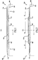
- Drum 100 has a cylindrically-shaped forming surface 101 that extends between opposing sides 102 and 104 and is substantially flat along the axial direction A and curved along circumferential direction C ( FIG. 8 ).
- Drum 100 is rotatable so as to allow various components to be presented onto the forming surface 101 in the construction of a tire.
- Drum 100 may include various internal features for positioning components placed onto surface 101.
- an air impermeable layer 106 (also referred to as an "inner liner") is placed onto forming surface 101 in a generally centered position between sides 102 and 104 as shown. While only one layer is illustrated, it should be understood that one or more air impermeable layers may be used.
- a pair of sidewall support inserts 108 and 110 are positioned onto the air impermeable layer 106. Each insert is placed at a predetermined distance from the sides 102 and 104 of drum 100 in an opposing manner and are generally equally spaced about center line C/L. The shape and size of the inserts is provided by way of example only and other configurations may be used. Additionally, while only a pair of inserts 108 are shown, more than one pair may be used to e.g., increase the sidewall strength of the assembled tire.
- a first reinforcing ply 112 and a second reinforcing ply 114 are placed onto the sidewall support inserts 108 and 110. While two plies 112 and 114 are shown in the figures, using the teachings disclosed herein it will be understood that a single reinforcing ply or more than two reinforcing plies may also be used. Additionally, where multiple reinforcing plies are used, such plies do not have to be applied over drum 100 at the same time.
- Plies 112 and 114 contain multiple cords and/or other reinforcing features that constrain the assembled tire while making plies 112 and 114 generally stiff and substantially non-expandable. As such, attempts to press plies 112 and 114 into contact with air impermeable layer 106 between inserts 108 and 110 can create creases as previously discussed. Accordingly, for this exemplary method of the present invention, plies 112 and 114 are placed onto sidewall support inserts 108 and 110 and are suspended over the forming surface 101 between the inserts 108 and 110. This creates a temporary cavity 116 extending circumferentially about drum 100 between air impermeable layer 106 and reinforcing ply 112.
- Each reinforcing ply includes a plurality of perforations along the circumferential direction. More particularly, as shown in FIG. 8 , reinforcing ply 112 includes a plurality of perforations 126 (e.g., holes or openings) that are spaced apart along circumferential direction C.
- each perforation 126 has a diameter in the range of about 2 mm to about 4 mm. In another exemplary embodiment, each perforation 126 has a diameter of about 3 mm or, for example, 3 mm ⁇ 0.5 mm.
- each perforation 126 is centrally positioned on reinforcing ply 112.
- perforations 126 should be located in the crown region of the tire.
- perforations 126 are within a range of about 0 to about 10 mm from centerline C/L.
- perforations 126 are positioned on or within ⁇ 0.5 mm of centerline C/L.
- Other placements may be used, provided perforations 126 are located in the crown region of the tire.
- Similar perforations are provided in reinforcing ply 114.
- a variety of techniques may be used to create perforations 126 in plies 112 and 114 as will be understood by one of skill in the art. The perforations can be created before plies 112 and 114 are applied or created as plies 112 and 114 are pulled onto drum 100.
- reinforcing plies 112 and 114 It is not necessary for the perforations in the reinforcing plies 112 and 114 to be aligned with each other. Also, while two plies 112 and 114 are shown, other constructions may also be used including a single reinforcing ply or more than two plies 112 and 114. In still another alternative, other components may be added between the application of reinforcing ply 112 and reinforcing ply 114. For example, reinforcing ply 112 may be positioned onto inserts 108 and 110.
- Additional sidewall reinforcement inserts may then be positioned into reinforcing ply 112 at positions axially outward of inserts 108 and 110 followed by the positioning of reinforcing ply 114 over or onto the same.
- reinforcing plies 112 and 114 are stitched against inserts 108 and 110 as well as air impermeable layer 106 as shown. More specifically, plies 112 and 114 are pressed towards the forming surface 101 at zones ST - which include inserts 108 and 110 and locations axially outward of inserts 108 and 110 as shown. This stitching leaves a portion of the plies 112 and 114 - designated as zone SU in FIG 2 - suspended over layer 106 between the radially outermost portion of inserts 108 and 110 so that cavity 116 remains.
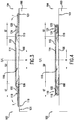
- a pair of bead fillers 122 and 124 as well as pair of circular bead elements 118 and 120 are positioned onto reinforcing ply 114 as shown in FIG. 3 .
- the shape and size of bead fillers 122 and 124 are provided by way of example only and other configurations may be used. Additionally, while only a pair of bead fillers 122 and 124 are shown, each filler may be constructed from one or more pieces in alternative embodiments of the invention.
- Each bead filler 122 and 124 and bead 118 and 120 is positioned axially outward of a respective sidewall support insert 108 and 110, respectively.
- ends 119 and 121 of the reinforcing plies 112 and 114 are turned up and over bead fillers 122 and 124 and circular bead elements 118 and 120 as indicated by arrows T.
- Several mechanisms can be used to turn up ends 119 and 121.
- forming surface 101 can be provided with pneumatically powered segments that can be inflated to lift portions of surface 101 and turn ends 119 and 121 over as shown. Other mechanisms may be used as well.
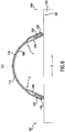
- a gas pressure (e.g., air) is delivered to the forming surface 101 of drum 100 so as to separate air impermeable layer 106 from surface 101.
- a gas pressure e.g., air
- small passages may be provided in drum 100 to supply a gas to the forming surface 101.
- air impermeable layer 106 will separate from forming surface 101 along the portion between bead elements 118 and 120 as shown.
- features associated with drum 100 are activated such that bead elements 118 and 120 are moved towards each other or axially inward as shown by arrows M.
- Such drum features may be activated so as to initiate the movement of bead elements 118 and 120 towards each other at the same time the delivery of the gas pressure is initiated.
- a predetermined interval of time may be allowed to lapse after initiating delivery of the gas pressure before initiating movement of the bead elements 118 and 120 towards each other using features of drum 100.
- reinforcing plies 112 and 114 allows air impermeable layer 106 to be forced against and simultaneously supported by plies 112 and 114,
- the perforations in plies 112 and 114 allow gas in cavity 116 to escape as air impermeable layer 106 moves towards plies 112 and 114 between e.g., the position shown in FIG. 5 and the position shown in FIG. 6 .
- the intermediate tire assembly 130 takes on a toroidal shape as shown in FIG. 7 .
- Protective sidewall rubber members can be added to side wall portions 128 and 130.
- a tread rubber (not shown) can be added to crown portion 132.
- the resulting intermediate tire assembly 132 can then be removed from forming drum 100 and placed into e.g., a curing press for molding and curing.
Landscapes
- Engineering & Computer Science (AREA)
- Mechanical Engineering (AREA)
- Tyre Moulding (AREA)
Description
- The subject matter of the present disclosure relates generally to method of adhering the inner liner of a tire to a reinforcing ply.
- Tires are commonly manufactured using of one or more building drums upon which the tire is constructed from multiple layers and components that are placed sequentially onto the drum. For example, in one technique, a layer of air impermeable rubber is laid onto the forming surface of a cylindrical drum. One or more carcass plies are placed onto the drum. A pair of circular beads are placed on opposing sides and may include bead wires and bead fillers. The plies are turned up and the beads are moved towards each other to create a toroidal shape. A sidewall protective rubber and a tread portion are added.
- The addition of rubber elements into the sidewalls of the tire can be desirable for certain tire applications. For example, the addition of rubber reinforcements into the sidewalls can be used along with other features to provide a tire that is capable of operating for a limited distance after losing inflation pressure. Such may allow the driver to reach a service center or other location more suitable than where the pressure loss occurred.
- Certain challenges, however, are presented in the manufacture of tires having e.g., reinforcement in the sidewalls. The forming drum is typically a cylindrical shape having a flat profile along the axial direction but may have recesses for accepting features such as circular beads. For designs where these reinforcements are presented onto the forming drum before a carcass ply or reinforcing ply is laid onto the forming drum, the reinforcements create a profile that is no longer flat along the axial direction of the drum. Presentation of a carcass ply onto this uneven profile can result in undesirable creases or wrinkles - particularly when attempting to press the carcass ply towards the forming drum to make contact with e.g., an air impermeable layer on the forming drum. In turn, these creases can lead to an undesirable orientation and positioning of cords and/or other reinforcing elements present in the reinforcing ply - referred to herein as deradialization. Also, the joining of the ends of the ply may no longer be uniform as the amount of overlap may be quite variable.
U.S. Patent No. 7,241,353 relates to method of manufacturing a tire having a crescent-shaped section using a building drum.U.S. 2005/002890 relates to a high crown, first stage tire building drum and a method of building a tire carcass.JP 2005 119227 - Accordingly, a method for assembling a tire having one or more reinforcements or supports in the sidewalls would be useful. More particularly, such a method that can be used to reduce or avoid creases or wrinkles that can lead to deradialization and/or non-uniformities in the joining of the ends of the plies would be beneficial.
- The present invention provides a method of assembling a tire having one or more reinforcements or supporting inserts in the sidewalls. The reinforcements are positioned onto one or more air impermeable layers, One or more reinforcing plies are positioned over the reinforcing supports and suspended therebetween. A gas pressure is used to expand the one or more air impermeable layers away from the forming drum and against a reinforcing ply. As such, the creases or wrinkles in the one or more reinforcing plies can be avoided along with other non-uniformities such as deradialization and/or an uneven overlap where the ends of a ply are joined. Additional objects and advantages of the invention will be set forth in part in the following description, or may be apparent from the description, or may be learned through practice of the invention,
- In one exemplary aspect, the present invention provides a method of assembling tire components on a tire building drum having a cylindrically-shaped forming surface extending between opposing sides of the drum. The drum defines axial and circumferential directions. The method comprises the steps of laying one or more air impermeable layers onto the forming surface; positioning a pair of sidewall support inserts onto the one or more air impermeable layers with each sidewall support insert spaced from a respective side of the drum; placing at least one reinforcing ply over the pair of sidewall support inserts on the drum so as to suspend over the forming surface the at least on reinforcing ply between the pair of sidewall support inserts, wherein the at least one reinforcing ply comprises a plurality of perforations centrally positioned on the at least one reinforcing ply and spaced apart along a circumferential direction of the drum; stitching the at least one reinforcing ply to the pair of sidewall support inserts and to the one or more air impermeable layers at locations axially outward of each sidewall support while leaving the reinforcing ply suspended between the pair of sidewall support inserts; depositing a pair of bead fillers onto the at least one reinforcing ply with each bead filler spaced from a side of the drum; locating a pair of circular bead elements onto the drum with each bead element positioned onto the at least one carcass ply; turning up edges of the at least one reinforcing ply over the pair of bead fillers and the pair of bead elements; delivering a gas pressure to the surface of the forming drum so as to separate the one or more air impermeable layers from the forming surface at locations between the bead elements; moving the bead elements toward each other along the axial direction of the drum during the step of delivering a gas pressure; and using the gas pressure to push the one or more air impermeable layers against the at least one reinforcing ply.
- These and other features, aspects and advantages of the present invention will become better understood with reference to the following description and appended claims. The accompanying drawings, which are incorporated in and constitute a part of this specification, illustrate embodiments of the invention and, together with the description, serve to explain the principles of the invention.
- A full and enabling disclosure of the present invention, including the best mode thereof, directed to one of ordinary skill in the art, is set forth in the specification, which makes reference to the appended figures, in which:
-
FIGS. 1 through 8 illustrate certain steps of an exemplary method of the present invention as may be used for assembling a tire. ForFIGS. 1 through 7 , each figure shows a cross-sectional view of certain components of an exemplary tire as presented to a tire building or form ing drum.FIG. 8 illustrates a perspective view of a building drum onto which certain components of an exemplary tire have been placed. - For purposes of describing the invention, reference now will be made in detail to embodiments of the invention, one or more examples of which are illustrated in the drawings. Each example is provided by way of explanation of the invention, not limitation of the invention.
- An exemplary method of the present invention is illustrated through various steps shown in
FIGS. 1 through 8 as will now be described. Beginning withFIG. 1 , atire building drum 100 is shown.Drum 100 has a cylindrically-shaped formingsurface 101 that extends betweenopposing sides FIG. 8 ).Drum 100 is rotatable so as to allow various components to be presented onto the formingsurface 101 in the construction of a tire.Drum 100 may include various internal features for positioning components placed ontosurface 101. - Initially, an air impermeable layer 106 (also referred to as an "inner liner") is placed onto forming
surface 101 in a generally centered position betweensides sidewall support inserts impermeable layer 106. Each insert is placed at a predetermined distance from thesides drum 100 in an opposing manner and are generally equally spaced about center line C/L. The shape and size of the inserts is provided by way of example only and other configurations may be used. Additionally, while only a pair ofinserts 108 are shown, more than one pair may be used to e.g., increase the sidewall strength of the assembled tire. - A first reinforcing
ply 112 and a second reinforcingply 114 are placed onto thesidewall support inserts plies drum 100 at the same time. -
Plies plies plies impermeable layer 106 betweeninserts plies sidewall support inserts surface 101 between theinserts temporary cavity 116 extending circumferentially aboutdrum 100 between airimpermeable layer 106 and reinforcingply 112. - Each reinforcing ply includes a plurality of perforations along the circumferential direction. More particularly, as shown in
FIG. 8 , reinforcingply 112 includes a plurality of perforations 126 (e.g., holes or openings) that are spaced apart along circumferential direction C. In one exemplary embodiment of the invention, eachperforation 126 has a diameter in the range of about 2 mm to about 4 mm. In another exemplary embodiment, eachperforation 126 has a diameter of about 3 mm or, for example, 3 mm ± 0.5 mm. - Additionally, for the exemplary embodiment illustrated, each
perforation 126 is centrally positioned on reinforcingply 112. In other embodiments,perforations 126 should be located in the crown region of the tire. For example, in one exemplary embodiment,perforations 126 are within a range of about 0 to about 10 mm from centerline C/L. In another exemplary embodiment,perforations 126 are positioned on or within ± 0.5 mm of centerline C/L. Other placements may be used, providedperforations 126 are located in the crown region of the tire. Similar perforations are provided in reinforcingply 114. A variety of techniques may be used to createperforations 126 inplies plies plies drum 100. - It is not necessary for the perforations in the reinforcing
plies plies plies ply 112 and reinforcingply 114. For example, reinforcingply 112 may be positioned ontoinserts ply 112 at positions axially outward ofinserts ply 114 over or onto the same. - Referring now to
FIG. 2 , reinforcingplies inserts impermeable layer 106 as shown. More specifically, plies 112 and 114 are pressed towards the formingsurface 101 at zones ST - which includeinserts inserts plies 112 and 114 - designated as zone SU inFIG 2 - suspended overlayer 106 between the radially outermost portion ofinserts cavity 116 remains. - A pair of
bead fillers circular bead elements ply 114 as shown inFIG. 3 . The shape and size ofbead fillers bead fillers bead filler bead sidewall support insert - Referring now to
FIGS. 3 and 4 , theends plies bead fillers circular bead elements surface 101 can be provided with pneumatically powered segments that can be inflated to lift portions ofsurface 101 and turn ends 119 and 121 over as shown. Other mechanisms may be used as well. - In
FIG. 5 , a gas pressure (e.g., air) is delivered to the formingsurface 101 ofdrum 100 so as to separate airimpermeable layer 106 fromsurface 101. For example, small passages may be provided indrum 100 to supply a gas to the formingsurface 101. As this gas is pressurized, airimpermeable layer 106 will separate from formingsurface 101 along the portion betweenbead elements bead elements bead elements bead elements drum 100. - As shown in
FIG. 6 , while the delivery of the pressurized gas fromdrum 100 continues, airimpermeable layer 106 will eventually contact reinforcingply 112. The force of gas pressure P against airimpermeable layer 106 and the movement ofbead elements 118 and 120 (along withbead fillers 122 and 142 and ends 119 and 121) axially inward will cause reinforcingplies Plies bead elements impermeable layer 106. More particularly, the flexibility oflayer 106 allows it to stretch to reachplies plies impermeable layer 106 to be forced against and simultaneously supported byplies plies cavity 116 to escape as airimpermeable layer 106 moves towardsplies FIG. 5 and the position shown inFIG. 6 . - As the air pressure is maintained against air
impermeable layer 106 andbead elements intermediate tire assembly 130 takes on a toroidal shape as shown inFIG. 7 . Protective sidewall rubber members (not shown) can be added toside wall portions crown portion 132. The resultingintermediate tire assembly 132 can then be removed from formingdrum 100 and placed into e.g., a curing press for molding and curing.
Claims (15)
- A method of assembling tire components on a tire building drum (100) having a cylindrically-shaped forming surface (101) extending between opposing sides (102, 104) of the drum, the drum defining axial and circumferential directions, the method comprising the steps of:laying one or more air impermeable layers (106) onto the forming surface;positioning a pair of sidewall support inserts (108, 110) onto the one or more air impermeable layers with each sidewall support insert spaced from a respective side of the drum;placing at least one reinforcing ply (112) over the pair of sidewall support inserts on the drum so as to suspend over the forming surface the at least one reinforcing ply between the pair of sidewall support inserts, wherein the at least one reinforcing ply comprises a plurality of perforations (126) centrally positioned on the at least one reinforcing ply and spaced apart along a circumferential direction of the drum;stitching the at least one reinforcing ply to the pair of sidewall support inserts and to the one or more air impermeable layers at locations axially outward of each sidewall support while leaving the reinforcing ply suspended between the pair of sidewall support inserts;depositing a pair of bead fillers (122, 124) onto the at least one reinforcing ply with each bead filler spaced from a side of the drum;locating a pair of circular bead elements (118, 120) onto the drum with each bead element positioned onto the at least one reinforcing ply;turning up edges of the at least one reinforcing ply over the pair of bead fillers and the pair of bead elements;delivering a gas pressure to the surface of the forming drum so as to separate the one or more air impermeable layers from the forming surface at locations between the bead elements;moving the bead elements toward each other along the axial direction of the drum during said step of delivering a gas pressure; andusing the gas pressure to push the one or more air impermeable layers away from the forming surface at locations between the bead elements and into contact with the at least one reinforcing ply.
- A method of assembling tire components as in claim 1, further comprising the step of
allowing gas located between the at least one air impermeable layer and the at least one reinforcing ply to pass through the perforations in the at least one reinforcing ply during said step of the using the gas pressure. - A method of assembling tire components as in claim 2, wherein said step of delivering and said step of moving are initiated simultaneously.
- A method of assembling tire components as in claim 3, further comprising the step of:
positioning tread rubber over a crown portion of the at least one carcass ply. - A method of assembling tire components as in claim 3, further comprising the step of:
placing a pair of sidewall rubber members onto sidewall portions of the at least one carcass ply. - A method of assembling tire components as in claim 1, further comprising the step of:
stretching the one or more air impermeable layer during said step of using the gas pressure. - A method of assembling tire components as in claim 1, further comprising the step of:
allowing gas located between the at least one air impermeable layer and the at least one reinforcing ply to pass through the perforations in the at least one reinforcing ply during said step of delivering. - A method of assembling tire components as in claim 1, further comprising the step of creating the plurality of perforations in the at least one reinforcing ply prior to said step of placing.
- A method of assembling tire components as in claim 1, wherein the perforations in the at least one reinforcing ply are in the range of about 1.5 mm to about 4.5 mm in diameter.
- A method of assembling tire components as in claim 1, wherein the perforations in the at least one reinforcing ply are about 3 mm in diameter.
- A method of assembling tire components as in claim 1, wherein the perforations in the at least one reinforcing ply are positioned within in a range of 0 to about 10 mm from a centerline of the at least one reinforcing ply.
- A method of assembling tire components as in claim 1, wherein the one or more air impermeable layers comprise two air impermeable layers.
- A method of assembling tire components as in claim 1, wherein the one or more reinforcing plies comprise two reinforcing plies and wherein each of the plies comprises a plurality of perforations centrally positioned on the at least one reinforcing ply and spaced apart along a circumferential direction of the tire to be built.
- A method of assembling tire components as in claim 1, wherein a first reinforcing ply is positioned over the pair of sidewall supports during said step of placing, and further comprising the step of delivering a second reinforcing ply over the pair of sidewall supports after said step of turning.
- A method of assembling tire components as in claim 1, wherein the step of placing creates a temporary cavity (116) extending circumferentially about the drum between the one or more air impermeable layers and the at least one reinforcing ply.
Applications Claiming Priority (1)
| Application Number | Priority Date | Filing Date | Title |
|---|---|---|---|
| PCT/US2012/043456 WO2013191692A1 (en) | 2012-06-21 | 2012-06-21 | Method for adhering an innerliner to a carcass ply of a tire |
Publications (3)
| Publication Number | Publication Date |
|---|---|
| EP2864112A1 EP2864112A1 (en) | 2015-04-29 |
| EP2864112A4 EP2864112A4 (en) | 2016-03-30 |
| EP2864112B1 true EP2864112B1 (en) | 2018-12-26 |
Family
ID=49769146
Family Applications (1)
| Application Number | Title | Priority Date | Filing Date |
|---|---|---|---|
| EP12879193.6A Active EP2864112B1 (en) | 2012-06-21 | 2012-06-21 | Method for adhering an innerliner to a carcass ply of a tire |
Country Status (5)
| Country | Link |
|---|---|
| US (1) | US9908302B2 (en) |
| EP (1) | EP2864112B1 (en) |
| KR (1) | KR101800170B1 (en) |
| CN (1) | CN104411478B (en) |
| WO (1) | WO2013191692A1 (en) |
Families Citing this family (5)
| Publication number | Priority date | Publication date | Assignee | Title |
|---|---|---|---|---|
| JP6295812B2 (en) * | 2014-05-09 | 2018-03-20 | 横浜ゴム株式会社 | Method and apparatus for manufacturing run-flat tire |
| JP6683470B2 (en) * | 2015-12-16 | 2020-04-22 | Toyo Tire株式会社 | Tire manufacturing method and unvulcanized tire |
| US10960627B2 (en) | 2017-09-01 | 2021-03-30 | The Goodyear Tire & Rubber Company | Method of making a tire |
| DE102020216103A1 (en) * | 2020-12-17 | 2022-06-23 | Continental Reifen Deutschland Gmbh | Method of building a vehicle tire with an inverse sidewall and apparatus for carrying out such a method |
| US20250303657A1 (en) * | 2022-05-12 | 2025-10-02 | Retyre As | Joining a tyre base layer |
Citations (1)
| Publication number | Priority date | Publication date | Assignee | Title |
|---|---|---|---|---|
| JP2005119227A (en) * | 2003-10-20 | 2005-05-12 | Yokohama Rubber Co Ltd:The | Tire molding method |
Family Cites Families (32)
| Publication number | Priority date | Publication date | Assignee | Title |
|---|---|---|---|---|
| US2409974A (en) * | 1942-08-06 | 1946-10-22 | Gen Tire & Rubber Co | Tire building machine |
| US2973799A (en) * | 1957-12-18 | 1961-03-07 | Goodrich Co B F | Vented rubberized fabric article and method of making same |
| US3722567A (en) * | 1970-12-15 | 1973-03-27 | Pneumatiques Caoutchouc Mfg | Radial-ply pneumatic tire |
| US4229246A (en) * | 1978-12-18 | 1980-10-21 | The Steelastic Company | Building drum assembly |
| US4226655A (en) * | 1979-01-02 | 1980-10-07 | The B. F. Goodrich Company | Method for building a tire |
| US4402783A (en) * | 1981-04-30 | 1983-09-06 | Nrm Corporation | Axially collapsible and expandable tire building drum |
| JPH05305682A (en) | 1992-03-04 | 1993-11-19 | Bridgestone Corp | Apparatus, method and drum for uniformly expanding diameter of cylindrical member and apparatus for uniformly expanding contracting diameter of cylindrical member |
| JP2644168B2 (en) * | 1993-07-14 | 1997-08-25 | 住友ゴム工業株式会社 | Former for tire molding machine |
| CA2121159C (en) | 1993-07-16 | 2005-03-29 | Kenneth Dean Conger | Contoured tire building drum and method of building an extended mobility tire |
| US6358346B1 (en) | 2000-07-28 | 2002-03-19 | The Goodyear Tire & Rubber Company | Method of building tire with composite ply structure |
| US6488797B1 (en) | 2000-05-12 | 2002-12-03 | Bridgestone/Firestone North American Tire, Llc | First stage run flat tire building drum and method of using same |
| JP4603736B2 (en) * | 2001-09-06 | 2010-12-22 | 株式会社ブリヂストン | Tire manufacturing method |
| US6769468B2 (en) | 2001-09-21 | 2004-08-03 | The Goodyear Tire & Rubber Company | Tire building drum having expandable center section and independently expandable bead lock assemblies in the end sections |
| EP1456007A1 (en) * | 2001-12-19 | 2004-09-15 | Pirelli Pneumatici S.p.A. | Elastomeric semifinished product for the production of a tyre liner, and tyre provided with said liner |
| WO2003089258A1 (en) * | 2002-04-19 | 2003-10-30 | Bridgestone Corporation | Run flat tire and method of manufacturing the tire |
| FR2855043B1 (en) | 2003-05-22 | 2006-08-11 | Oreal | MAKE-UP COMPOSITION FOR THE SKIN, AND MORE PARTICULARLY A FLUID FOUNDATION-TYPE COMPOSITION, WITH OPTIMIZED APPLICATION QUALITIES |
| US20050028920A1 (en) | 2003-08-04 | 2005-02-10 | Roedseth John Kolbjoern | High crown first stage tire building drum |
| JP2005238654A (en) * | 2004-02-26 | 2005-09-08 | Sumitomo Rubber Ind Ltd | Raw tire manufacturing method |
| CN1960851B (en) * | 2004-04-30 | 2010-05-26 | 倍耐力轮胎股份公司 | Method and apparatus for manufacturing run-flat tires for automobile wheels |
| DE102004032508A1 (en) | 2004-07-06 | 2006-02-16 | Continental Aktiengesellschaft | Method and device for constructing a radial tire |
| JP4537806B2 (en) * | 2004-08-31 | 2010-09-08 | 住友ゴム工業株式会社 | Pneumatic tire and manufacturing method thereof |
| US7670449B2 (en) | 2005-11-22 | 2010-03-02 | The Goodyear Tire & Rubber Company | Method of manufacturing tire with turned down ply construction |
| EP1867467B1 (en) * | 2006-06-16 | 2009-04-15 | Societe de Technologie Michelin | Method of applying a carcass reinforcing ply. |
| US8215356B2 (en) * | 2006-12-21 | 2012-07-10 | The Goodyear Tire & Rubber Company | Tire with composite ply structure and envelope turnup |
| WO2008099473A1 (en) * | 2007-02-14 | 2008-08-21 | Toyo Tire & Rubber Co., Ltd. | Boring device of tire constitution member |
| US8316903B2 (en) * | 2007-10-01 | 2012-11-27 | The Goodyear Tire & Rubber Company | Pneumatic tire having built-in sealant layer and preparation thereof |
| JP4989449B2 (en) * | 2007-12-25 | 2012-08-01 | 横浜ゴム株式会社 | Pneumatic tire manufacturing method and pneumatic tire |
| JP5305682B2 (en) | 2008-02-15 | 2013-10-02 | 日本ぱちんこ部品株式会社 | Game machine |
| KR101429671B1 (en) * | 2008-04-18 | 2014-08-13 | 피렐리 타이어 소시에떼 퍼 아찌오니 | Process and Apparatus for Assembling Tyres |
| US9649818B2 (en) * | 2008-05-28 | 2017-05-16 | Pirelli Tyre S.P.A. | Process and apparatus for building tyres |
| US8205652B2 (en) | 2008-12-12 | 2012-06-26 | The Goodyear Tire & Rubber Company | Self-supporting pneumatic tire with optimized ply line |
| US8785028B1 (en) * | 2012-02-08 | 2014-07-22 | NTS Works, Inc. | High conductivity battery contact |
-
2012
- 2012-06-21 KR KR1020147035717A patent/KR101800170B1/en active Active
- 2012-06-21 EP EP12879193.6A patent/EP2864112B1/en active Active
- 2012-06-21 US US14/406,789 patent/US9908302B2/en active Active
- 2012-06-21 CN CN201280074063.0A patent/CN104411478B/en active Active
- 2012-06-21 WO PCT/US2012/043456 patent/WO2013191692A1/en not_active Ceased
Patent Citations (1)
| Publication number | Priority date | Publication date | Assignee | Title |
|---|---|---|---|---|
| JP2005119227A (en) * | 2003-10-20 | 2005-05-12 | Yokohama Rubber Co Ltd:The | Tire molding method |
Also Published As
| Publication number | Publication date |
|---|---|
| US20150165707A1 (en) | 2015-06-18 |
| WO2013191692A1 (en) | 2013-12-27 |
| KR101800170B1 (en) | 2017-11-22 |
| US9908302B2 (en) | 2018-03-06 |
| EP2864112A4 (en) | 2016-03-30 |
| EP2864112A1 (en) | 2015-04-29 |
| CN104411478B (en) | 2017-05-10 |
| KR20150022862A (en) | 2015-03-04 |
| CN104411478A (en) | 2015-03-11 |
Similar Documents
| Publication | Publication Date | Title |
|---|---|---|
| CN103587134B (en) | Tire assembly drum without sleeve | |
| JP4777585B2 (en) | First stage creation drum for manufacturing run flat tires and method of using the same | |
| EP2864112B1 (en) | Method for adhering an innerliner to a carcass ply of a tire | |
| US7241353B2 (en) | Method of manufacturing tire | |
| EP2923827B1 (en) | Method for manufacturing a motorcycle tire | |
| EP1793981B1 (en) | A method and a plant for manufacturing tyres | |
| CN104884239B (en) | Method and apparatus for building tires for vehicle wheels | |
| EP2239130B1 (en) | Pneumatic tire manufacturing method, and pneumatic tire | |
| JP6510308B2 (en) | Method of manufacturing pneumatic tire, and shaping apparatus | |
| WO2006033119A1 (en) | A method and an apparatus for manufacturing tyres | |
| JP2011230424A (en) | Method of manufacturing green tire, and side bladder used in the same | |
| CN109421302B (en) | Method of building a tyre | |
| JP2005335081A (en) | Pneumatic tire manufacturing method | |
| US9290062B2 (en) | Tyre and tyre building method | |
| JP6484107B2 (en) | Raw tire forming method | |
| CN106142609B (en) | Method for manufacturing pneumatic tire, molding device, and pneumatic tire | |
| JP2005212278A (en) | Tire manufacturing method | |
| JP6510309B2 (en) | Method of manufacturing pneumatic tire, and shaping apparatus | |
| JP2019098640A (en) | Method of manufacturing pneumatic tire | |
| JP2006503727A (en) | Manufacturing method and apparatus for vehicle wheel tire | |
| JP2019104111A (en) | Production method of pneumatic tire | |
| JP2009131967A (en) | Pneumatic tire and its manufacturing method | |
| JP2016049708A (en) | Tire manufacturing method |
Legal Events
| Date | Code | Title | Description |
|---|---|---|---|
| PUAI | Public reference made under article 153(3) epc to a published international application that has entered the european phase |
Free format text: ORIGINAL CODE: 0009012 |
|
| 17P | Request for examination filed |
Effective date: 20141212 |
|
| AK | Designated contracting states |
Kind code of ref document: A1 Designated state(s): AL AT BE BG CH CY CZ DE DK EE ES FI FR GB GR HR HU IE IS IT LI LT LU LV MC MK MT NL NO PL PT RO RS SE SI SK SM TR |
|
| AX | Request for extension of the european patent |
Extension state: BA ME |
|
| DAX | Request for extension of the european patent (deleted) | ||
| RA4 | Supplementary search report drawn up and despatched (corrected) |
Effective date: 20160225 |
|
| RIC1 | Information provided on ipc code assigned before grant |
Ipc: B29D 30/36 20060101AFI20160219BHEP Ipc: B29D 30/20 20060101ALI20160219BHEP Ipc: B29D 30/06 20060101ALN20160219BHEP |
|
| STAA | Information on the status of an ep patent application or granted ep patent |
Free format text: STATUS: EXAMINATION IS IN PROGRESS |
|
| 17Q | First examination report despatched |
Effective date: 20161201 |
|
| RAP1 | Party data changed (applicant data changed or rights of an application transferred) |
Owner name: COMPAGNIE GENERALE DES ETABLISSEMENTS MICHELIN |
|
| RAP1 | Party data changed (applicant data changed or rights of an application transferred) |
Owner name: COMPAGNIE GENERALE DES ETABLISSEMENTS MICHELIN |
|
| GRAP | Despatch of communication of intention to grant a patent |
Free format text: ORIGINAL CODE: EPIDOSNIGR1 |
|
| STAA | Information on the status of an ep patent application or granted ep patent |
Free format text: STATUS: GRANT OF PATENT IS INTENDED |
|
| RIC1 | Information provided on ipc code assigned before grant |
Ipc: B29D 30/06 20060101ALN20180717BHEP Ipc: B29D 30/20 20060101ALI20180717BHEP Ipc: B29D 30/36 20060101AFI20180717BHEP |
|
| INTG | Intention to grant announced |
Effective date: 20180802 |
|
| RAP1 | Party data changed (applicant data changed or rights of an application transferred) |
Owner name: COMPAGNIE GENERALE DES ETABLISSEMENTS MICHELIN |
|
| GRAS | Grant fee paid |
Free format text: ORIGINAL CODE: EPIDOSNIGR3 |
|
| GRAA | (expected) grant |
Free format text: ORIGINAL CODE: 0009210 |
|
| STAA | Information on the status of an ep patent application or granted ep patent |
Free format text: STATUS: THE PATENT HAS BEEN GRANTED |
|
| AK | Designated contracting states |
Kind code of ref document: B1 Designated state(s): AL AT BE BG CH CY CZ DE DK EE ES FI FR GB GR HR HU IE IS IT LI LT LU LV MC MK MT NL NO PL PT RO RS SE SI SK SM TR |
|
| REG | Reference to a national code |
Ref country code: GB Ref legal event code: FG4D |
|
| REG | Reference to a national code |
Ref country code: CH Ref legal event code: EP |
|
| REG | Reference to a national code |
Ref country code: AT Ref legal event code: REF Ref document number: 1080822 Country of ref document: AT Kind code of ref document: T Effective date: 20190115 |
|
| REG | Reference to a national code |
Ref country code: DE Ref legal event code: R096 Ref document number: 602012055308 Country of ref document: DE |
|
| REG | Reference to a national code |
Ref country code: IE Ref legal event code: FG4D |
|
| REG | Reference to a national code |
Ref country code: NL Ref legal event code: FP |
|
| PG25 | Lapsed in a contracting state [announced via postgrant information from national office to epo] |
Ref country code: LT Free format text: LAPSE BECAUSE OF FAILURE TO SUBMIT A TRANSLATION OF THE DESCRIPTION OR TO PAY THE FEE WITHIN THE PRESCRIBED TIME-LIMIT Effective date: 20181226 Ref country code: HR Free format text: LAPSE BECAUSE OF FAILURE TO SUBMIT A TRANSLATION OF THE DESCRIPTION OR TO PAY THE FEE WITHIN THE PRESCRIBED TIME-LIMIT Effective date: 20181226 Ref country code: BG Free format text: LAPSE BECAUSE OF FAILURE TO SUBMIT A TRANSLATION OF THE DESCRIPTION OR TO PAY THE FEE WITHIN THE PRESCRIBED TIME-LIMIT Effective date: 20190326 Ref country code: LV Free format text: LAPSE BECAUSE OF FAILURE TO SUBMIT A TRANSLATION OF THE DESCRIPTION OR TO PAY THE FEE WITHIN THE PRESCRIBED TIME-LIMIT Effective date: 20181226 Ref country code: FI Free format text: LAPSE BECAUSE OF FAILURE TO SUBMIT A TRANSLATION OF THE DESCRIPTION OR TO PAY THE FEE WITHIN THE PRESCRIBED TIME-LIMIT Effective date: 20181226 Ref country code: NO Free format text: LAPSE BECAUSE OF FAILURE TO SUBMIT A TRANSLATION OF THE DESCRIPTION OR TO PAY THE FEE WITHIN THE PRESCRIBED TIME-LIMIT Effective date: 20190326 |
|
| REG | Reference to a national code |
Ref country code: LT Ref legal event code: MG4D |
|
| PG25 | Lapsed in a contracting state [announced via postgrant information from national office to epo] |
Ref country code: GR Free format text: LAPSE BECAUSE OF FAILURE TO SUBMIT A TRANSLATION OF THE DESCRIPTION OR TO PAY THE FEE WITHIN THE PRESCRIBED TIME-LIMIT Effective date: 20190327 Ref country code: RS Free format text: LAPSE BECAUSE OF FAILURE TO SUBMIT A TRANSLATION OF THE DESCRIPTION OR TO PAY THE FEE WITHIN THE PRESCRIBED TIME-LIMIT Effective date: 20181226 Ref country code: AL Free format text: LAPSE BECAUSE OF FAILURE TO SUBMIT A TRANSLATION OF THE DESCRIPTION OR TO PAY THE FEE WITHIN THE PRESCRIBED TIME-LIMIT Effective date: 20181226 Ref country code: SE Free format text: LAPSE BECAUSE OF FAILURE TO SUBMIT A TRANSLATION OF THE DESCRIPTION OR TO PAY THE FEE WITHIN THE PRESCRIBED TIME-LIMIT Effective date: 20181226 |
|
| REG | Reference to a national code |
Ref country code: AT Ref legal event code: MK05 Ref document number: 1080822 Country of ref document: AT Kind code of ref document: T Effective date: 20181226 |
|
| PG25 | Lapsed in a contracting state [announced via postgrant information from national office to epo] |
Ref country code: PL Free format text: LAPSE BECAUSE OF FAILURE TO SUBMIT A TRANSLATION OF THE DESCRIPTION OR TO PAY THE FEE WITHIN THE PRESCRIBED TIME-LIMIT Effective date: 20181226 Ref country code: IT Free format text: LAPSE BECAUSE OF FAILURE TO SUBMIT A TRANSLATION OF THE DESCRIPTION OR TO PAY THE FEE WITHIN THE PRESCRIBED TIME-LIMIT Effective date: 20181226 Ref country code: CZ Free format text: LAPSE BECAUSE OF FAILURE TO SUBMIT A TRANSLATION OF THE DESCRIPTION OR TO PAY THE FEE WITHIN THE PRESCRIBED TIME-LIMIT Effective date: 20181226 Ref country code: PT Free format text: LAPSE BECAUSE OF FAILURE TO SUBMIT A TRANSLATION OF THE DESCRIPTION OR TO PAY THE FEE WITHIN THE PRESCRIBED TIME-LIMIT Effective date: 20190426 Ref country code: ES Free format text: LAPSE BECAUSE OF FAILURE TO SUBMIT A TRANSLATION OF THE DESCRIPTION OR TO PAY THE FEE WITHIN THE PRESCRIBED TIME-LIMIT Effective date: 20181226 |
|
| PG25 | Lapsed in a contracting state [announced via postgrant information from national office to epo] |
Ref country code: SK Free format text: LAPSE BECAUSE OF FAILURE TO SUBMIT A TRANSLATION OF THE DESCRIPTION OR TO PAY THE FEE WITHIN THE PRESCRIBED TIME-LIMIT Effective date: 20181226 Ref country code: EE Free format text: LAPSE BECAUSE OF FAILURE TO SUBMIT A TRANSLATION OF THE DESCRIPTION OR TO PAY THE FEE WITHIN THE PRESCRIBED TIME-LIMIT Effective date: 20181226 Ref country code: SM Free format text: LAPSE BECAUSE OF FAILURE TO SUBMIT A TRANSLATION OF THE DESCRIPTION OR TO PAY THE FEE WITHIN THE PRESCRIBED TIME-LIMIT Effective date: 20181226 Ref country code: IS Free format text: LAPSE BECAUSE OF FAILURE TO SUBMIT A TRANSLATION OF THE DESCRIPTION OR TO PAY THE FEE WITHIN THE PRESCRIBED TIME-LIMIT Effective date: 20190426 Ref country code: RO Free format text: LAPSE BECAUSE OF FAILURE TO SUBMIT A TRANSLATION OF THE DESCRIPTION OR TO PAY THE FEE WITHIN THE PRESCRIBED TIME-LIMIT Effective date: 20181226 |
|
| REG | Reference to a national code |
Ref country code: DE Ref legal event code: R097 Ref document number: 602012055308 Country of ref document: DE |
|
| PG25 | Lapsed in a contracting state [announced via postgrant information from national office to epo] |
Ref country code: DK Free format text: LAPSE BECAUSE OF FAILURE TO SUBMIT A TRANSLATION OF THE DESCRIPTION OR TO PAY THE FEE WITHIN THE PRESCRIBED TIME-LIMIT Effective date: 20181226 Ref country code: AT Free format text: LAPSE BECAUSE OF FAILURE TO SUBMIT A TRANSLATION OF THE DESCRIPTION OR TO PAY THE FEE WITHIN THE PRESCRIBED TIME-LIMIT Effective date: 20181226 |
|
| PLBE | No opposition filed within time limit |
Free format text: ORIGINAL CODE: 0009261 |
|
| STAA | Information on the status of an ep patent application or granted ep patent |
Free format text: STATUS: NO OPPOSITION FILED WITHIN TIME LIMIT |
|
| 26N | No opposition filed |
Effective date: 20190927 |
|
| PG25 | Lapsed in a contracting state [announced via postgrant information from national office to epo] |
Ref country code: MC Free format text: LAPSE BECAUSE OF FAILURE TO SUBMIT A TRANSLATION OF THE DESCRIPTION OR TO PAY THE FEE WITHIN THE PRESCRIBED TIME-LIMIT Effective date: 20181226 |
|
| REG | Reference to a national code |
Ref country code: CH Ref legal event code: PL |
|
| GBPC | Gb: european patent ceased through non-payment of renewal fee |
Effective date: 20190621 |
|
| PG25 | Lapsed in a contracting state [announced via postgrant information from national office to epo] |
Ref country code: SI Free format text: LAPSE BECAUSE OF FAILURE TO SUBMIT A TRANSLATION OF THE DESCRIPTION OR TO PAY THE FEE WITHIN THE PRESCRIBED TIME-LIMIT Effective date: 20181226 |
|
| REG | Reference to a national code |
Ref country code: BE Ref legal event code: MM Effective date: 20190630 |
|
| PG25 | Lapsed in a contracting state [announced via postgrant information from national office to epo] |
Ref country code: TR Free format text: LAPSE BECAUSE OF FAILURE TO SUBMIT A TRANSLATION OF THE DESCRIPTION OR TO PAY THE FEE WITHIN THE PRESCRIBED TIME-LIMIT Effective date: 20181226 |
|
| PG25 | Lapsed in a contracting state [announced via postgrant information from national office to epo] |
Ref country code: GB Free format text: LAPSE BECAUSE OF NON-PAYMENT OF DUE FEES Effective date: 20190621 Ref country code: IE Free format text: LAPSE BECAUSE OF NON-PAYMENT OF DUE FEES Effective date: 20190621 |
|
| PG25 | Lapsed in a contracting state [announced via postgrant information from national office to epo] |
Ref country code: LI Free format text: LAPSE BECAUSE OF NON-PAYMENT OF DUE FEES Effective date: 20190630 Ref country code: LU Free format text: LAPSE BECAUSE OF NON-PAYMENT OF DUE FEES Effective date: 20190621 Ref country code: BE Free format text: LAPSE BECAUSE OF NON-PAYMENT OF DUE FEES Effective date: 20190630 Ref country code: CH Free format text: LAPSE BECAUSE OF NON-PAYMENT OF DUE FEES Effective date: 20190630 |
|
| PG25 | Lapsed in a contracting state [announced via postgrant information from national office to epo] |
Ref country code: CY Free format text: LAPSE BECAUSE OF FAILURE TO SUBMIT A TRANSLATION OF THE DESCRIPTION OR TO PAY THE FEE WITHIN THE PRESCRIBED TIME-LIMIT Effective date: 20181226 |
|
| PG25 | Lapsed in a contracting state [announced via postgrant information from national office to epo] |
Ref country code: HU Free format text: LAPSE BECAUSE OF FAILURE TO SUBMIT A TRANSLATION OF THE DESCRIPTION OR TO PAY THE FEE WITHIN THE PRESCRIBED TIME-LIMIT; INVALID AB INITIO Effective date: 20120621 Ref country code: MT Free format text: LAPSE BECAUSE OF FAILURE TO SUBMIT A TRANSLATION OF THE DESCRIPTION OR TO PAY THE FEE WITHIN THE PRESCRIBED TIME-LIMIT Effective date: 20181226 |
|
| PG25 | Lapsed in a contracting state [announced via postgrant information from national office to epo] |
Ref country code: MK Free format text: LAPSE BECAUSE OF FAILURE TO SUBMIT A TRANSLATION OF THE DESCRIPTION OR TO PAY THE FEE WITHIN THE PRESCRIBED TIME-LIMIT Effective date: 20181226 |
|
| PGFP | Annual fee paid to national office [announced via postgrant information from national office to epo] |
Ref country code: NL Payment date: 20240619 Year of fee payment: 13 |
|
| PGFP | Annual fee paid to national office [announced via postgrant information from national office to epo] |
Ref country code: DE Payment date: 20250618 Year of fee payment: 14 |
|
| PGFP | Annual fee paid to national office [announced via postgrant information from national office to epo] |
Ref country code: FR Payment date: 20250625 Year of fee payment: 14 |
|
| REG | Reference to a national code |
Ref country code: NL Ref legal event code: MM Effective date: 20250701 |
|
| PG25 | Lapsed in a contracting state [announced via postgrant information from national office to epo] |
Ref country code: NL Free format text: LAPSE BECAUSE OF NON-PAYMENT OF DUE FEES Effective date: 20250701 |