EP2863733B1 - Sample collection and transfer assembly and related methods - Google Patents
Sample collection and transfer assembly and related methods Download PDFInfo
- Publication number
- EP2863733B1 EP2863733B1 EP13735126.8A EP13735126A EP2863733B1 EP 2863733 B1 EP2863733 B1 EP 2863733B1 EP 13735126 A EP13735126 A EP 13735126A EP 2863733 B1 EP2863733 B1 EP 2863733B1
- Authority
- EP
- European Patent Office
- Prior art keywords
- sample
- cartridge
- aperture
- housing member
- cover
- Prior art date
- Legal status (The legal status is an assumption and is not a legal conclusion. Google has not performed a legal analysis and makes no representation as to the accuracy of the status listed.)
- Active
Links
Images


Classifications
-
- A—HUMAN NECESSITIES
- A61—MEDICAL OR VETERINARY SCIENCE; HYGIENE
- A61B—DIAGNOSIS; SURGERY; IDENTIFICATION
- A61B10/00—Other methods or instruments for diagnosis, e.g. instruments for taking a cell sample, for biopsy, for vaccination diagnosis; Sex determination; Ovulation-period determination; Throat striking implements
- A61B10/0045—Devices for taking samples of body liquids
-
- A—HUMAN NECESSITIES
- A01—AGRICULTURE; FORESTRY; ANIMAL HUSBANDRY; HUNTING; TRAPPING; FISHING
- A01J—MANUFACTURE OF DAIRY PRODUCTS
- A01J5/00—Milking machines or devices
- A01J5/04—Milking machines or devices with pneumatic manipulation of teats
- A01J5/045—Taking milk-samples
-
- A—HUMAN NECESSITIES
- A61—MEDICAL OR VETERINARY SCIENCE; HYGIENE
- A61B—DIAGNOSIS; SURGERY; IDENTIFICATION
- A61B90/00—Instruments, implements or accessories specially adapted for surgery or diagnosis and not covered by any of the groups A61B1/00 - A61B50/00, e.g. for luxation treatment or for protecting wound edges
- A61B90/90—Identification means for patients or instruments, e.g. tags
- A61B90/94—Identification means for patients or instruments, e.g. tags coded with symbols, e.g. text
- A61B90/96—Identification means for patients or instruments, e.g. tags coded with symbols, e.g. text using barcodes
-
- A—HUMAN NECESSITIES
- A61—MEDICAL OR VETERINARY SCIENCE; HYGIENE
- A61B—DIAGNOSIS; SURGERY; IDENTIFICATION
- A61B90/00—Instruments, implements or accessories specially adapted for surgery or diagnosis and not covered by any of the groups A61B1/00 - A61B50/00, e.g. for luxation treatment or for protecting wound edges
- A61B90/90—Identification means for patients or instruments, e.g. tags
- A61B90/98—Identification means for patients or instruments, e.g. tags using electromagnetic means, e.g. transponders
-
- B—PERFORMING OPERATIONS; TRANSPORTING
- B01—PHYSICAL OR CHEMICAL PROCESSES OR APPARATUS IN GENERAL
- B01L—CHEMICAL OR PHYSICAL LABORATORY APPARATUS FOR GENERAL USE
- B01L3/00—Containers or dishes for laboratory use, e.g. laboratory glassware; Droppers
- B01L3/50—Containers for the purpose of retaining a material to be analysed, e.g. test tubes
- B01L3/502—Containers for the purpose of retaining a material to be analysed, e.g. test tubes with fluid transport, e.g. in multi-compartment structures
-
- G—PHYSICS
- G01—MEASURING; TESTING
- G01N—INVESTIGATING OR ANALYSING MATERIALS BY DETERMINING THEIR CHEMICAL OR PHYSICAL PROPERTIES
- G01N1/00—Sampling; Preparing specimens for investigation
- G01N1/02—Devices for withdrawing samples
- G01N1/10—Devices for withdrawing samples in the liquid or fluent state
-
- B—PERFORMING OPERATIONS; TRANSPORTING
- B01—PHYSICAL OR CHEMICAL PROCESSES OR APPARATUS IN GENERAL
- B01L—CHEMICAL OR PHYSICAL LABORATORY APPARATUS FOR GENERAL USE
- B01L2300/00—Additional constructional details
- B01L2300/04—Closures and closing means
- B01L2300/046—Function or devices integrated in the closure
- B01L2300/047—Additional chamber, reservoir
-
- B—PERFORMING OPERATIONS; TRANSPORTING
- B01—PHYSICAL OR CHEMICAL PROCESSES OR APPARATUS IN GENERAL
- B01L—CHEMICAL OR PHYSICAL LABORATORY APPARATUS FOR GENERAL USE
- B01L2300/00—Additional constructional details
- B01L2300/06—Auxiliary integrated devices, integrated components
- B01L2300/0627—Sensor or part of a sensor is integrated
- B01L2300/0663—Whole sensors
-
- B—PERFORMING OPERATIONS; TRANSPORTING
- B01—PHYSICAL OR CHEMICAL PROCESSES OR APPARATUS IN GENERAL
- B01L—CHEMICAL OR PHYSICAL LABORATORY APPARATUS FOR GENERAL USE
- B01L2400/00—Moving or stopping fluids
- B01L2400/04—Moving fluids with specific forces or mechanical means
- B01L2400/0403—Moving fluids with specific forces or mechanical means specific forces
- B01L2400/0406—Moving fluids with specific forces or mechanical means specific forces capillary forces
-
- B—PERFORMING OPERATIONS; TRANSPORTING
- B01—PHYSICAL OR CHEMICAL PROCESSES OR APPARATUS IN GENERAL
- B01L—CHEMICAL OR PHYSICAL LABORATORY APPARATUS FOR GENERAL USE
- B01L2400/00—Moving or stopping fluids
- B01L2400/04—Moving fluids with specific forces or mechanical means
- B01L2400/0403—Moving fluids with specific forces or mechanical means specific forces
- B01L2400/0457—Moving fluids with specific forces or mechanical means specific forces passive flow or gravitation
-
- G—PHYSICS
- G01—MEASURING; TESTING
- G01N—INVESTIGATING OR ANALYSING MATERIALS BY DETERMINING THEIR CHEMICAL OR PHYSICAL PROPERTIES
- G01N1/00—Sampling; Preparing specimens for investigation
- G01N1/28—Preparing specimens for investigation including physical details of (bio-)chemical methods covered elsewhere, e.g. G01N33/50, C12Q
- G01N1/2813—Producing thin layers of samples on a substrate, e.g. smearing, spinning-on
-
- G—PHYSICS
- G01—MEASURING; TESTING
- G01N—INVESTIGATING OR ANALYSING MATERIALS BY DETERMINING THEIR CHEMICAL OR PHYSICAL PROPERTIES
- G01N33/00—Investigating or analysing materials by specific methods not covered by groups G01N1/00 - G01N31/00
- G01N33/02—Food
- G01N33/04—Dairy products
Definitions
- the present invention relates to a collection device suitable for collecting a milk sample from a milk producing animal, such as a cow or goat.
- the present invention further relates to sample collection and transfer assembly including a sample collection device and a sample cartridge.
- Mastitis is the inflammation of the mammary gland caused by microorganisms that invade one or more quadrants of the bovine udder, multiply, and produce toxins that are harmful to the mammary gland. Economic loss to mastitis in the United States is estimated to be over $ 2 billion. This is approximately 10% of the total value of farm milk sales, and about two-thirds of this loss is due to reduced milk production in subclinically infected cows.
- subclinical mastitis there may be no visible signs of the disease, and diagnosis of subclinical mastitis may be performed by a somatic cell count (SCC) of the milk.
- SCC somatic cell count
- the SCC is the number of leukocytes or white blood cells per volume of milk and is also used as an index of milk quality. It has also been recognized that there are multiple types of leukocytes, each with its own significance. In milk from a healthy animal, the predominant cell types are lymphocytes, followed by lesser numbers of neutrophils and macrophages. The percentages of each kind of cell rise and fall as part of the immune response to infection. Those percentages, "the milk leukocyte differential", cell count represent the unique immune status of an individual quarter udder, at a specific point in time for better diagnosis of subclinical mastitis.
- MMDS machine milk differential smear
- U.S. Patent Application Publication No. 2009/0233329 to Rodriguez discloses a wedge microfluidic slide chamber for detecting mastitis or other diseases from a body fluid of a mammal, such as from cow's milk.
- the wedge-shaped chamber uses capillary action to fill the chamber with the sample as a "self-preparing wet smear" with a meta-chromatic stain.
- the wedge-shaped microscope slide with the stained sample may be analyzed by visual identification and direct observation or by imaging instruments using computer-enhanced digital camera images. Accordingly, mastitis may be detected more easily with such a self-preparing wet smear.
- Milk collection techniques for such a slide may be time consuming and/or difficult.
- a sample from each quadrant of the cow's udder may be collected in different containers and pipetted by an operator into the wedge-shaped slide chamber for further analysis, for example, by an imaging instrument or reader.
- the liquid samples may be stored in separate containers prior to analysis, and the tracking and/or storage of such samples may present various challenges, for example, to track which sample came from which cow and from which quadrant of the cow.
- WO02/48681 describes a device for depositing cells from a fluid suspension onto a solid substrate.
- cellular samples such as cervical cells can be obtained from a cell suspension and then transferred to a microscope slide for analysis.
- the device includes a first chamber for containing the fluid suspension, the chamber being divided into two or more contiguous zones.
- the device also includes a second chamber for receiving excess fluid suspension and a channel through which excess fluid suspension can be displaced from the first chamber to the second. Retaining means of retaining the solid substrate relative to the first chamber are also included.
- the device also includes a displacement device that has a member slideable within the first chamber.
- the displacement device includes at least a body element, a porous element, and a fluid absorbing element.
- the present claimed invention provides a collection device suitable for collecting a milk sample from a milk producing animal, such as a cow or goat, as defined in claim 1.
- This collection device includes a base housing member having at least one chamber.
- a cover housing member has at least one aperture therein, and the cover housing member is configured to cover the base housing member such that the at least one aperture is positioned in fluid communication with the at least one chamber.
- the cover housing member includes a cartridge holding interface configured to releasably engage with a cartridge that is configured to cover and receive a fluid from the at least one chamber via the at least one aperture.
- the at least one chamber comprises a plurality of chambers and the at least one aperture comprises a plurality of corresponding apertures.
- Each of the plurality of chambers comprises a wall portion that extends away from the base housing member and defines the chamber and, in an assembled position, is configured to extend into a corresponding sealing feature on the cover housing member to seal a sample therein.
- the base housing member comprises a central portion and a perimeter portion, and the wall portion of the plurality of chambers has a height that is higher in the central portion than at the perimeter portion of the base housing member, such that milk from a cow, goat or other milk producing animal may be collected in the chambers of the base housing.
- the cartridge holding interface comprises a retaining wall or pins configured to abut an outer perimeter of the cartridge.
- the cartridge holding interface may include at least one notch and/or groove that is configured to engage a corresponding notch and/or groove on the cartridge.
- the cartridge holding interface may include at least one hook member that is configured to engage and retain an edge portion of the cartridge.
- the cartridge holding interface is configured to interface with the cartridge in a single orientation.
- the base housing member and the cover housing member include cooperating sealing members that are configured to seal each of the plurality of chambers.
- the cooperating sealing members include a base sealing feature between the plurality of wells on the base housing member, and a cover sealing feature on the cover housing member configured to engage with the base sealing feature and to thereby fluidly seal each of the plurality of wells.
- One of the base sealing feature and the cover sealing feature may include a groove and the other of the base sealing feature and the cover sealing feature comprises a ridge that is configured to be received in the groove and form a snug fit.
- the chambers overlap a central portion and a perimeter portion of the base housing member, and the chambers comprise a wall that has a height that is higher in the central portion than at the perimeter portion.
- the present claimed invention also provides a collection and transfer assembly as defined in claim 9.
- This collection and transfer assembly includes a collection device as defined above.
- the collection and transfer assembly further includes a sample cartridge comprising at least one sample area having at least one cartridge aperture that is configured to receive a fluid from the at least one chamber via the at least one housing aperture.
- the cartridge holding interface on the cover housing member is configured to releasably engage with the sample cartridge.
- the sample cartridge has a first major surface opposite a second major surface, the at least one sample area is on the first major surface and faces away from the cover housing member, and the at least one cartridge aperture is on the second major surface and fluidly connects the housing aperture to the sample area.
- the sample cartridge has a first major surface opposite a second major surface, and the at least one sample area is on the second major surface and faces toward the cover housing member, and the at least one cartridge aperture is on the second major surface and fluidly connects the housing aperture to the sample area.
- the cartridge holding interface comprises a retaining wall or protruding pins or posts configured to abut an outer perimeter of the cartridge.
- the cartridge holding interface may include at least one notch and/or groove that is configured to engage a corresponding notch and/or groove on the cartridge.
- the cartridge holding interface may include at least one hook member that is configured to engage and retain an edge portion of the cartridge.
- the cartridge holding interface is configured to interface with the cartridge in a single orientation.
- the base housing member and the cover housing member include cooperating sealing members that are configured to seal each of the plurality of chambers.
- the cooperating sealing members include a base sealing feature between the plurality of wells on the base housing member, and a cover sealing feature on the cover housing member configured to engage with the base sealing feature and to thereby fluidly seal each of the plurality of wells.
- One of the base sealing feature and the cover sealing feature may include a groove and the other of the base sealing feature and the cover sealing feature may include a ridge that is configured to be received in the groove and form a snug fit.
- the chambers overlap a central portion and a perimeter portion of the base housing member, and the chambers include a wall that has a height that is higher in the central portion than at the perimeter portion.
- the present claimed invention also provides a method of collecting a sample as defined in claim 14.
- This method includes collecting a sample in at least one chamber of a base housing member of a collection device as defined above.
- a cover housing member is placed on the base housing member of the collection device.
- the cover housing member has at least one housing aperture therein.
- the cover housing member is configured to cover the base housing member such that the at least one housing aperture is positioned in fluid communication with the at least one chamber.
- the cover housing member further includes a cartridge holding interface.
- a sample cartridge is positioned on the cartridge holding interface.
- the sample cartridge further includes at least one sample area having at least one cartridge aperture that is configured to receive a fluid from the at least one chamber via the at least one housing aperture.
- the cover and base housing members are inverted such that the sample flows from the at least one chamber to the at least one sample area via the at least one housing aperture and the at least one cartridge aperture.
- the method further includes placing the cartridge in an imaging reader.
- the method further includes storing the collection device and the sample cartridge before the inverting step.
- phrases such as “between X and Y” and “between about X and Y” should be interpreted to include X and Y.
- phrases such as “between about X and Y” mean “between about X and about Y.”
- phrases such as “from about X to Y” mean “from about X to about Y.”
- spatially relative terms such as “under,” “below,” “lower,” “over,” “upper” and the like, may be used herein for ease of description to describe one element or feature's relationship to another element(s) or feature(s) as illustrated in the figures. It will be understood that the spatially relative terms are intended to encompass different orientations of the device in use or operation in addition to the orientation depicted in the figures. For example, if the device in the figures is inverted, elements described as “under” or “beneath” other elements or features would then be oriented “over” the other elements or features.
- the exemplary term “under” can encompass both an orientation of "over” and “under.”
- the device may be otherwise oriented (rotated 90 degrees or at other orientations) and the spatially relative descriptors used herein interpreted accordingly.
- the terms “upwardly,” “downwardly,” “vertical,” “horizontal” and the like are used herein for the purpose of explanation only unless specifically indicated otherwise.
- a collection and transfer assembly 10 includes a collection device 100 and a sample cartridge 400 .
- the collection device 100 includes a base housing 200 and cover housing 300 .
- the base housing 200 includes four chambers 210 that are configured to collect a sample.
- the sample cartridge 400 includes four sample areas 430 , which are configured to receive the sample from the chambers 210 for further analysis.
- the collection and transfer assembly 10 may be used to collect a liquid biological fluid sample, for example, a milk sample from a milk producing animal, such as a cow or goat. Accordingly, the milk sample may be conveniently collected and transferred to the microscope slide for further analysis, for example, in a microscope or imaging reader.
- the sample areas 430 may include a wedge-shaped microscope slide such that capillary action fills the slide 430 with the sample as a "self-preparing wet smear" with a meta-chromatic stain.
- the stain may be preloaded onto the sample areas 430 .
- the wedge-shaped microscope slide with the stained sample may be analyzed by visual identification and direct observation or by imaging instruments using computer-enhanced digital camera images. Examples of suitable imaging readers and wedge-shaped slides are described in U.S. Patent Application Publication No. 2009/0233329 to Rodriguez .
- the cartridge for imaging a specimen on an automated microscope may include a substrate, a chamber or generally planar imaging surface on or in the substrate for containing or supporting the specimen; a plurality of exogeneous targets in the chamber or on the surface; and (optionally but in some embodiments preferably) at least one optically transparent wall formed on or forming the chamber to facilitate imaging the contents thereof.
- the base housing 200 defines four chambers 210 having centrally elevated splash-guard walls 212 , a groove 214 , and an outer lip 220 that includes a handle portion 222 and a perimeter portion 224 .
- the cover housing 300 includes a plurality of apertures 316 , an outer lip 320 includes a handle portion 322 and a perimeter portion 324 .
- the cover housing 300 further defines a cartridge holding interface 330 that is sized and configured to releasably engage with and/or abut the cartridge 400 ( Figures 1-2 ).
- the cartridge holding interface 330 includes various retaining features, including retaining walls 332 , retaining members or hooks 334 , and interlocking member or notch 336 , and retaining pins 338 .
- the cover housing 300 includes chamber covering sealing 310 that correspond to the chambers 210 of the base housing 200 .
- the chamber sealing features 310 are configured to seal and/or fluidly isolate different samples that are collected in each of the four chambers 210 of the base housing 200 .
- the chamber sealing features 310 include a sealing rib 314 on a ridge interface 315 , and sealing protrusions 318 .
- the sealing rib 314 is configured to mate with the groove 214 of the base housing 200
- the sealing protrusions 318 are configured to extend into the chambers 210 of the base housing 200 such that a fluid sample in each of the chambers 210 is generally prevented from leaking into other ones of the chambers 210 .
- the base housing 200 and the cover housing 300 interlock with on another to generally seal each of the sample chambers 210 to reduce or prevent leaking between chambers 210 . Therefore, the samples from the quadrants of the cow may be separately stored and/or tested separately.
- the lips 220 , 320 may engage with one another (such as in a snap- or press-fit) to form an outer seal.
- the sealing protrusions 318 of the cover housing 300 extend into the chambers 210 to further seal the sample chambers 210 .
- the sealing rib 314 and ridge interface 315 of the cover housing 300 mate with the central groove 214 of the base housing 200 to form a sufficiently snug fit to generally seal the four chambers 210 and/or reduce or prevent sample fluid from one chamber 210 leaking to another chamber 210 .
- the sample cartridge 400 includes an outer perimeter 420 , sample areas 430 , and apertures 450 .
- the outer perimeter 420 has an asymmetric shape and orientation features, such as notches 422 , for interacting with the cartridge holding interface 330 of the collection device cover housing 300 .
- the sample areas 430 include a transparent or translucent slide 432 , such as a microscope slide, that is configured to hold and retain the fluid sample for analysis by a slide reader (not shown).
- the apertures 450 are sized and configured to provide a fluid connection with the apertures 350 of the cover housing 300 .
- a fluid sample collected in the chambers 210 may be transferred to the sample areas 430 of the sample cartridge 400 by inverting the collection and transfer chamber 10 .
- the fluid sample flows from the base chamber 210 to the cover housing 300 and into the sample area 430 via the cover housing apertures 350 and the sample cartridge apertures 450 .
- corresponding interlocking features such as notches and/or grooves 336 and 422 may be included in the outer perimeter 420 of the cartridge 400 .
- the cartridge holding interface 330 and the outer perimeter 420 of the cartridge 400 may be asymmetric such that the cartridge 400 fits into the cartridge holding interface 330 in only a single orientation.
- the hooks 334 may further hold the cartridge 400 in position such that the assembly 10 may be inverted or transported without the cartridge 400 becoming dislodged from the cartridge holding interface 330 .
- a sample cartridge 500 includes an outer perimeter 520 , sample areas 530 , and apertures 550 .
- the sample areas 530 include a transparent or translucent slide 532 and sample entry passages 534 .
- the slide 532 may be a microscope slide that is configured to hold and retain the fluid sample for analysis by a slide reader (not shown).
- the entry passages 534 are positioned so as to provide a fluid passageway from the apertures 350 of the cover housing 300 . Accordingly, when the device 100 is inverted, the sample flows from the chambers 210 to the sample areas 530 via the apertures 350 and the passages 534 .
- the slide 532 is on a side of the cartridge 500 that faces the collection device cover housing 300 .
- the outer perimeter 520 of the cartridge 500 has an asymmetric shape and orientation features, such as notches 522 , for interacting with the cartridge holding interface 330 of the collection device cover housing 300 . Therefore, the cartridges 400, 500 may be configured to mate with the cartridge holding interface 330 in a single orientation. In this configuration, the sample may be collected in the chambers 210 corresponding to predefined quadrant of the cow or other sample source. The cartridges 400, 500 may be configured to fit on the holding interface 330 in a single orientation so that the source of the sample from one of the predefined quadrants is known.
- the cartridges 400, 500 may also fit into a reader (not shown) in a single orientation so that the reader associates the sample results with a predefined quadrant of the cow or other sample source.
- the sample results may be recorded by a user or by a computer processor associate with the reader.
- the sample results may be recorded together with the sample source, such as a cow identification number and a quadrant number based on the particular chamber 210 and corresponding sample area 430, 530 .
- the base housing 200 may include nesting features 260 that generally correspond to the cartridge holding interface 330 or other top features of the cover housing 300 .
- the nesting features 260 permit the stacking of two or more collection and transfer assemblies 10 by resting the nesting features 260 against the cartridge holding interface 330 of an adjacent assembly 10 .
- the cartridge holding interface 330 is shaped such that it fits inside the nesting features 260 of an adjacent assembly 10 .
- the collection devices 100 may be filled with fluid samples, and then stored in the stacked configuration, The fluid samples may be collected in the sample chambers 210 without being added to the cartridges 400 during storage, Accordingly, contact between the fluid sample and the assay and/or stain in the sample area 430 may be avoided until just prior to analyzing the sample in the cartridge 400 when the collection and transfer assembly 10 may be agitated and inverted to thereby cause fluid to flow from the chamber 210 to the sample area 430 via the cover apertures 350 and the cartridge apertures 450 . Therefore, the user may collect samples from multiple bovine animals prior to analysis and store the samples without contacting the sample with the assay and/or stain in the sample area 430 until the user chooses to analyze the cartridges 400 .
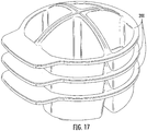
- the chambers 210 of the base housing 200 may be tapered to permit nesting of the sample collection base housing 200 for ease of transport and/or shipping as illustrated in Figure 17 .
- a fluid sample for example, milk from a cow, goat or other milk producing animal, may be collected in the chambers of the base housing (Block 1000 ; Figure 18 ).
- the chambers 210 of the base housing 200 include splash-guard walls 212 that are sufficiently high that splatter may be reduced between the chambers 210 .
- Fluid milk samples may be collected directly from each of the four quadrants or teats of the cow generally without mixing samples collected from other quadrants of the milk-producing animal due, in part, to the high splash-guard walls 212 .
- the cover housing may then be placed on the base housing (Block 1002 ; Figure 18 ).
- the cover housing may be a temporary plug housing, such as the housing 1500 of Figure 25 that is placed on the base housing 1200 for storage, transportation and/or agitation of the sample.
- the device assembly may be stored (Block 1006 ). In some embodiments, the assembly may be stored prior to analysis and/or filing the cartridge sample areas. However, in some embodiments, the sample areas of the cartridge may be filed with the fluid sample prior to storage. Before the sample cartridge is filled, the plug (if used) is replaced with the transfer cover and the sample cartridge is positioned on the cartridge holding interface of the cover housing.
- the sample may be agitated, for example, in the base housing, because fluids such as milk may separate into high- and low-fat components (Block 1008 ).
- the cover housing 1500 of Figure 25 was used, then the cover housing 1500 is first replaced with the cover housing 1200 and cartridge 1400 (Block 1007 ).
- the cover and the base housing may be inverted such that the sample flows into the cartridge sample areas via the cover housing apertures and the cartridge apertures (Block 1010 ).
- the sample cartridge may then be removed from the cover housing and placed in a reader (Block 1012 ) for further analysis.
- sample areas 430 and corresponding cartridge filling apertures 450 , cover housing filling apertures 350 , and collection chambers 210 any number of sample areas 430 may be provided.
- a single sample area may be used with corresponding filling apertures and a single collection chamber.
- a collection and transfer assembly 1010 includes a collection device 1100 and a sample cartridge 1400 .
- the collection device 1100 includes a base housing 1200 and a cover housing 1300 .
- the base housing 1200 includes four generally cylindrical chambers 1210 and on a base or main portion 1220 .
- the chambers 1210 include a wall portion that extends away from the main portion 1220 and into corresponding, cooperating cover sealing features 1310 on the cover housing 1300 .
- the sealing features 1310 cover the chambers 1210 and may form a tight fit to substantially isolate and reduce or prevent leakage from the chambers 1210 .
- the cover housing sealing features 1310 further include apertures 1350 .
- the sample cartridge 1400 includes sample areas 1430 , which are defined by sample slides 1432 .
- the sample areas 1430 include apertures 1452 that cooperate with the apertures 1350 of the cover housing 1300 .
- a milk sample may be collected in the chambers 1210 of the base housing 1200 and sealed by the cover housing 1300 .
- the milk sample may be received in the sample areas 1430 of the sample cartridge 1400 when the assembly 1010 is inverted, and the milk sample flows from the chambers 1210 via the apertures 1350 and 1452 and into the sample area 1430 .
- the cover housing 1300 includes a holding interface 1330 having various retaining features 1332 , 1334 and 1336 for retaining the sample cartridge 1400 .
- the retaining features 1332, 1334 and 1336 may be assymetric such that the cartridge 1400 fits into the interface 1330 in a single orientation.
- the chambers 1210 of the base housing 1200 are illustrated in additional detail. As illustrated, the chambers 1210 include asymmetric or angled walls that may reduce splashing or contamination from one chamber to another because the wall height of the chambers 1210 is greater toward the central region of the base housing 1200 .
- the base housing 1200 and the cover housing 1300 may include various features that interact for stability of assembly and/or so that the base housing 1200 and the cover housing 1300 fit together in a single orientation.
- the base housing 1200 further includes protrusions 1212 and 1214 that interact with corresponding features of the cover housing 1300 as shown in Figure 22 .
- the cover portion includes a notch 1312 , an aperture 1314 and a stabilization arm 1316 .
- the protrusion 1212 of the base housing 1200 is received in the notch 1312
- the protrusion 1214 is received in the aperture 1314 .
- the stabilization arm 1316 rests on the main portion 1220 of the base housing 1200 for stability.
- the cartridge 1400 includes a glass plate 1410 having microscope cover slips 1432 affixed thereto, and a frame member 1420 that defines sample collection apertures 1450 .
- the slides 1432 may be configured in a wedge-shape such that capillary action files the slides 1432 with the sample as a "self-preparing we smear" with a meta-chromatic stain, which may be preloaded into the sample areas 1430 .
- the apertures 1350 protrude from the cover housing member 1300 such that the apertures 1350 form a fluid connection with a corresponding feature in the cartridge 1400 , such as the sample collection apertures 1450 to thereby fill the sample area 1430 .
- the apertures 1350 may protrude from the cover housing 1300 and fit into a corresponding well or other collection feature (such as the apertures 1450 ) on the cartridge 1400 to reduce or prevent leaking between the chambers 1210 , the sealing features 1310 and the sample areas 1430 .
- the cover housing used for transfer may be substituted with a plug assembly that caps the fluid in the base housing for storage and/or transportation.
- the plug may be configured to allow stackability.
- the fluid inside the base housing may be agitated before removing the plug assembly and replacing it with the cover housing used for transfer of the fluid to the cartridge.
- a cover housing or plug 1500 is optionally positioned on top of the base housing 1200 for storage and/or transport.
- the plug 1500 includes a directional arrow 1510 for indicating to the user the correct orientation of the plug 1500 . Accordingly, the sample may be stored in the base housing 1200 and protected by the plug 1500 , and the plug 1500 may be removed and the cover housing 1300 positioned thereon as described herein to transfer the sample to the cartridge 1400 .
- various tracking techniques may be used to identify a particular sample with an animal.
- the collection and transfer devices and/or the sample cartridges described herein may include a write-on label and/or a bar code label and/or an RFID tag for purposes of identifying the origin of the sample, such as a cow identification number.
- the sample cartridges described herein may be placed in a reader or imager for further analysis.
- the sample comprises cells to be imaged and/or counted by the reader, the cells may be stained by a suitable stain, including fluorescent stains such as acridine orange ( see, e.g ., US Patent No. 3,883,247 ).
- the cartridges described herein may use exogeneous targets as discussed below.
- Automated microscopes generally include a specimen support stage (e.g., configured for holding or securing a sample cartridge as described above), an objective lens, a camera operatively associated with the objective lens, at least one drive assembly operatively associated with said support stage and/or said objective lens.
- a specimen support stage e.g., configured for holding or securing a sample cartridge as described above
- an objective lens e.g., an objective lens
- a camera operatively associated with the objective lens
- at least one drive assembly operatively associated with said support stage and/or said objective lens.
- Examples of such microscopes include but are not limited to those described in US Patents Nos. 4,810,869 ; 5,483,055 ; 5,647,025 ; 5,790,710 ; 6,869,570 ; 7,141,773 ; and 8,014,583 .
- such apparatus includes a controller that is operatively associated with the camera and the at least one drive assembly which controller is configured through hardware and/or software to carry out an autofocus method as described herein (generally prior to acquisition of an image of the specimen or sample through the camera), typically through calculating a focus score.
- the focus score can be calculated by any suitable technique, including but not limited to those described in F. Groen et al., A comparison of different focus functions for use in autofocus algorithms, Cytometry 6, 81-91 (1985 ). Difference from the background, given a uniform background, can be calculated a number of ways, including but not limited to differences in contrast, gradient, and variance.
- the exogenous target should be visible by the particular optical system in use. This will depend on the magnification, excitation wavelength, size of field of view, etc. This will influence decisions on which size, shape, emission wavlengths, etc. of the texture.
- the exogenous target should be distinguishable from the target objects.
- the The exogeneous target reside at sustantially the same (or a known distance from) the focal plane of the target objects (e.g., be mixed with a biological sample suspected of containing cells to be imaged and/or counted, and/or placed in the same chamber as will contain a biological sample comprising cells to be imaged and/or counted).
- the exogeneous target should be of a size, shape, and number so as to not substantially obscure the view of the intended target objects, such as cells to be imaged and/or counted. And,the exogenous target should provide sufficient contrast with an empty field of view so as to provide an adequate focal peak and allow for reliable, reasonably rapid, and/or robust focusing.
- the exogenous targets may be formed of any suitable material, including organic polymers, inorganic materials (including crystalline materials, amorphous materials, metals, etc.) and composites thereof.
- the exogenous targets may be contained loosely within the chamber, fixed to one wall of the chamber, or surface to be imaged (e.g., by adhesive, by electrostatic, hydrophilic, or hydrophobic interaction, covalent bond directly or through a linking group, etc.), and/or formed on one wall of the chamber (e.g., by molding, etching, painting, silkscreening, lithography, etc.).
- the exogenous targets may be opaque or transparent. When transparent the targets may be "tinted" so as to transmit light therethrough at a predetermined wavelength (for example, so that they appear red, green, blue, yellow, etc., to a human observer).
- the exogenous targets may be regular or irregular in shape (for example, cylinders, spheres, cubes, pyramids, prisms, cones, rods, etc.).
- the targets have an average diameter of from 0.1, 0.5 or 1 micrometers up to 2, 5, or 10 micrometers.
- the number of exogenous targets is not critical, but in some embodiments the speed of the autofocus process can be increased by increasing, at least to a point, the number of exogenous targets in the chamber so that the targets are readily located in the automated microscope.
- a plurality of targets are included in the sample chamber (e.g., 2, 4, 6, 8 or 10 targets, up to 100, 200, 400, 600 or 800 exogenous targets, or more)
- plurality preferably consists of or consists essentially of targets having substantially the same size, shape, and optical characteristics.
- the targets are beads, such as fluorescent microbeads.
- microbeads are commonly available and used for calibrating flow cytometers or fluorescent microscopes (see, e.g., US Patents Nos. 4,698,262 ; 4,714,682 ; and 4,868,126 ).
- the targets are preferably optically distinguishable from cells to be counted (and hence would not be useful as calibration standards for the particular cells to be counted and/or imaged by the methods described herein).
- Optically distinguishable may be achieved by any suitable technique, such as by utilizing targets of a different and distinguishable shape from the cells to be counted, by utilizing targets that emit, transmit, and/or reflect light at a different wavelength from the cells to be counted when under the same illumination conditions, and combinations thereof.
Description
- The present invention relates to a collection device suitable for collecting a milk sample from a milk producing animal, such as a cow or goat. The present invention further relates to sample collection and transfer assembly including a sample collection device and a sample cartridge.
- Mastitis is the inflammation of the mammary gland caused by microorganisms that invade one or more quadrants of the bovine udder, multiply, and produce toxins that are harmful to the mammary gland. Economic loss to mastitis in the United States is estimated to be over $ 2 billion. This is approximately 10% of the total value of farm milk sales, and about two-thirds of this loss is due to reduced milk production in subclinically infected cows.
- In subclinical mastitis, there may be no visible signs of the disease, and diagnosis of subclinical mastitis may be performed by a somatic cell count (SCC) of the milk. The SCC is the number of leukocytes or white blood cells per volume of milk and is also used as an index of milk quality. It has also been recognized that there are multiple types of leukocytes, each with its own significance. In milk from a healthy animal, the predominant cell types are lymphocytes, followed by lesser numbers of neutrophils and macrophages. The percentages of each kind of cell rise and fall as part of the immune response to infection. Those percentages, "the milk leukocyte differential", cell count represent the unique immune status of an individual quarter udder, at a specific point in time for better diagnosis of subclinical mastitis.
- One method for detecting the milk leukocyte differential is using flow-cytometry, which is an expensive, sophisticated tool typically only found in top research laboratories and generally not practical for the farmer. Another method for detecting the milk leukocyte differential is the "manual milk differential smear" (MMDS), which is a difficult and time consuming procedure, and is subject to great variability, even when performed by highly trained laboratory technologists. Both flow-cytometry and MMDS present practical difficulties for field research or a barn environment.
-
U.S. Patent Application Publication No. 2009/0233329 to Rodriguez discloses a wedge microfluidic slide chamber for detecting mastitis or other diseases from a body fluid of a mammal, such as from cow's milk. The wedge-shaped chamber uses capillary action to fill the chamber with the sample as a "self-preparing wet smear" with a meta-chromatic stain. The wedge-shaped microscope slide with the stained sample may be analyzed by visual identification and direct observation or by imaging instruments using computer-enhanced digital camera images. Accordingly, mastitis may be detected more easily with such a self-preparing wet smear. - Milk collection techniques for such a slide, however, may be time consuming and/or difficult. Typically, a sample from each quadrant of the cow's udder may be collected in different containers and pipetted by an operator into the wedge-shaped slide chamber for further analysis, for example, by an imaging instrument or reader. Moreover, it may be desirable to pipette the sample into the self-preparing wet smear relatively soon before placing the microscope slide into the imaging instrument or reader. The liquid samples may be stored in separate containers prior to analysis, and the tracking and/or storage of such samples may present various challenges, for example, to track which sample came from which cow and from which quadrant of the cow.
-
WO02/48681 - The present claimed invention provides a collection device suitable for collecting a milk sample from a milk producing animal, such as a cow or goat, as defined in claim 1. This collection device includes a base housing member having at least one chamber. A cover housing member has at least one aperture therein, and the cover housing member is configured to cover the base housing member such that the at least one aperture is positioned in fluid communication with the at least one chamber. The cover housing member includes a cartridge holding interface configured to releasably engage with a cartridge that is configured to cover and receive a fluid from the at least one chamber via the at least one aperture. The at least one chamber comprises a plurality of chambers and the at least one aperture comprises a plurality of corresponding apertures. Each of the plurality of chambers comprises a wall portion that extends away from the base housing member and defines the chamber and, in an assembled position, is configured to extend into a corresponding sealing feature on the cover housing member to seal a sample therein. The base housing member comprises a central portion and a perimeter portion, and the wall portion of the plurality of chambers has a height that is higher in the central portion than at the perimeter portion of the base housing member, such that milk from a cow, goat or other milk producing animal may be collected in the chambers of the base housing.
- In some embodiments, the cartridge holding interface comprises a retaining wall or pins configured to abut an outer perimeter of the cartridge. The cartridge holding interface may include at least one notch and/or groove that is configured to engage a corresponding notch and/or groove on the cartridge. The cartridge holding interface may include at least one hook member that is configured to engage and retain an edge portion of the cartridge.
- In some embodiments, the cartridge holding interface is configured to interface with the cartridge in a single orientation.
- The base housing member and the cover housing member include cooperating sealing members that are configured to seal each of the plurality of chambers. In some embodiments, the cooperating sealing members include a base sealing feature between the plurality of wells on the base housing member, and a cover sealing feature on the cover housing member configured to engage with the base sealing feature and to thereby fluidly seal each of the plurality of wells. One of the base sealing feature and the cover sealing feature may include a groove and the other of the base sealing feature and the cover sealing feature comprises a ridge that is configured to be received in the groove and form a snug fit. In some embodiments, the chambers overlap a central portion and a perimeter portion of the base housing member, and the chambers comprise a wall that has a height that is higher in the central portion than at the perimeter portion.
- The present claimed invention also provides a collection and transfer assembly as defined in claim 9. This collection and transfer assembly includes a collection device as defined above. The collection and transfer assembly further includes a sample cartridge comprising at least one sample area having at least one cartridge aperture that is configured to receive a fluid from the at least one chamber via the at least one housing aperture. The cartridge holding interface on the cover housing member is configured to releasably engage with the sample cartridge.
- In some embodiments, the sample cartridge has a first major surface opposite a second major surface, the at least one sample area is on the first major surface and faces away from the cover housing member, and the at least one cartridge aperture is on the second major surface and fluidly connects the housing aperture to the sample area. In some embodiments, the sample cartridge has a first major surface opposite a second major surface, and the at least one sample area is on the second major surface and faces toward the cover housing member, and the at least one cartridge aperture is on the second major surface and fluidly connects the housing aperture to the sample area.
- In some embodiments, the cartridge holding interface comprises a retaining wall or protruding pins or posts configured to abut an outer perimeter of the cartridge. The cartridge holding interface may include at least one notch and/or groove that is configured to engage a corresponding notch and/or groove on the cartridge. The cartridge holding interface may include at least one hook member that is configured to engage and retain an edge portion of the cartridge.
- In some embodiments, the cartridge holding interface is configured to interface with the cartridge in a single orientation.
- The base housing member and the cover housing member include cooperating sealing members that are configured to seal each of the plurality of chambers. In some embodiments, the cooperating sealing members include a base sealing feature between the plurality of wells on the base housing member, and a cover sealing feature on the cover housing member configured to engage with the base sealing feature and to thereby fluidly seal each of the plurality of wells. One of the base sealing feature and the cover sealing feature may include a groove and the other of the base sealing feature and the cover sealing feature may include a ridge that is configured to be received in the groove and form a snug fit. In some embodiments, the chambers overlap a central portion and a perimeter portion of the base housing member, and the chambers include a wall that has a height that is higher in the central portion than at the perimeter portion.
- The present claimed invention also provides a method of collecting a sample as defined in claim 14. This method includes collecting a sample in at least one chamber of a base housing member of a collection device as defined above. A cover housing member is placed on the base housing member of the collection device. The cover housing member has at least one housing aperture therein. The cover housing member is configured to cover the base housing member such that the at least one housing aperture is positioned in fluid communication with the at least one chamber. The cover housing member further includes a cartridge holding interface. A sample cartridge is positioned on the cartridge holding interface. The sample cartridge further includes at least one sample area having at least one cartridge aperture that is configured to receive a fluid from the at least one chamber via the at least one housing aperture. The cover and base housing members are inverted such that the sample flows from the at least one chamber to the at least one sample area via the at least one housing aperture and the at least one cartridge aperture.
- In some embodiments, the method further includes placing the cartridge in an imaging reader.
- In some embodiments, the method further includes storing the collection device and the sample cartridge before the inverting step.
- The accompanying drawings, which are incorporated in and constitute a part of the specification, illustrate embodiments of the invention and, together with the description, serve to explain principles of the invention.
-
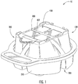
Figure 1 is a front perspective view of a collection and transfer device with a sample cartridge according to some embodiments. -
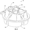
Figure 2 is a back perspective view of the collection and transfer device ofFigure 1 . -
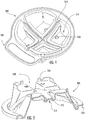
Figure 3 is a front perspective view of a base housing and a cover housing of the collection and transfer device ofFigure 1 in an open configuration. -
Figure 4 is an interior perspective view of the cover housing of the collection and transfer device ofFigure 1 . -
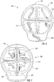
Figure 5 is a cross-sectional perspective view of the cover housing of the collection and transfer device ofFigure 1 . -
Figure 6 is a top view of the base housing of the collection and transfer device ofFigure 1 . -
Figure 7 is a top view of the cover housing of the collection and transfer ofFigure 1 . -
Figure 8 is a bottom perspective view of the cartridge device ofFigure 1 . -
Figure 9 is a cross-sectional top perspective view of the cartridge device ofFigure 1 . -
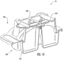
Figure 10 is a cross-sectional perspective view of the collection and transfer device and the cartridge ofFigure 1 . -
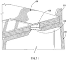
Figure 11 is an exploded cross-sectional perspective view of the collection and transfer device interface with the cartridge device ofFigure 1 . -
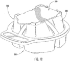
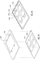
Figure 12 is a perspective view of a collection and transfer device and a sample cartridge device according to some embodiments. -
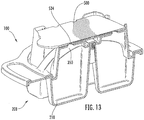
Figure 13 is a cross-sectional perspective view of the collection and transfer device ofFigure 12 . -
Figure 14 is an exploded cross-cross sectional perspective view of the collection and transfer device interface with the cartridge device ofFigure 12 . -
Figure 15 is a bottom perspective view of the collection and transfer device base housing ofFigure 1 . -
Figure 16 is a cross-sectional perspective side view of two collection and transfer devices with corresponding sample cartridges in a nesting configuration according to some embodiments. -
Figure 17 is a perspective side view of a plurality of the base housings of collection and transfer devices in a nesting configuration according to some embodiments. -
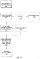
Figure 18 is a flowchart illustrating operations according to some embodiments. -
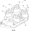
Figure 19 is a front perspective view of a collection and transfer device with a sample cartridge according to some embodiments. -
Figure 20 is a front perspective view of a collection and transfer device with the sample cartridge removed according to some embodiments. -
Figure 21 is a front perspective view of the base housing of the collection and transfer device ofFigure 20 . -
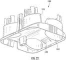
Figure 22 is a bottom perspective view of the cover housing of the collection and transfer device ofFigure 20 . -
Figure 23 is an exploded perspective view of a sample cartridge according to some embodiments. -
Figure 24 is an assembled view of the sample cartridge ofFigure 23 . -
Figure 25 is a front perspective view of the base housing of the collection and transfer device with a cover housing or plug according to some embodiments. - The present invention now will be described hereinafter with reference to the accompanying drawings and examples, in which embodiments of the invention are shown. This invention may, however, be embodied in many different forms and should not be construed as limited to the embodiments set forth herein. Rather, these embodiments are provided so that this disclosure will be thorough and complete, and will fully convey the scope of the invention to those skilled in the art.
- Like numbers refer to like elements throughout. In the figures, the thickness of certain lines, layers, components, elements or features may be exaggerated for clarity.
- The terminology used herein is for the purpose of describing particular embodiments only and is not intended to be limiting of the invention. As used herein, the singular forms "a," "an" and "the" are intended to include the plural forms as well, unless the context clearly indicates otherwise. It will be further understood that the terms "comprises" and/or "comprising," when used in this specification, specify the presence of stated features, steps, operations, elements, and/or components, but do not preclude the presence or addition of one or more other features, steps, operations, elements, components, and/or groups thereof. As used herein, the term "and/or" includes any and all combinations of one or more of the associated listed items. As used herein, phrases such as "between X and Y" and "between about X and Y" should be interpreted to include X and Y. As used herein, phrases such as "between about X and Y" mean "between about X and about Y." As used herein, phrases such as "from about X to Y" mean "from about X to about Y."
- Unless otherwise defined, all terms (including technical and scientific terms) used herein have the same meaning as commonly understood by one of ordinary skill in the art to which this invention belongs. It will be further understood that terms, such as those defined in commonly used dictionaries, should be interpreted as having a meaning that is consistent with their meaning in the context of the specification and relevant art and should not be interpreted in an idealized or overly formal sense unless expressly so defined herein. Well-known functions or constructions may not be described in detail for brevity and/or clarity.
- It will be understood that when an element is referred to as being "on," "attached" to, "connected" to, "coupled" with, "contacting," etc., another element, it can be directly on, attached to, connected to, coupled with or contacting the other element or intervening elements may also be present. In contrast, when an element is referred to as being, for example, "directly on," "directly attached" to, "directly connected" to, "directly coupled" with or "directly contacting" another element, there are no intervening elements present. It will also be appreciated by those of skill in the art that references to a structure or feature that is disposed "adjacent" another feature may have portions that overlap or underlie the adjacent feature.
- Spatially relative terms, such as "under," "below," "lower," "over," "upper" and the like, may be used herein for ease of description to describe one element or feature's relationship to another element(s) or feature(s) as illustrated in the figures. It will be understood that the spatially relative terms are intended to encompass different orientations of the device in use or operation in addition to the orientation depicted in the figures. For example, if the device in the figures is inverted, elements described as "under" or "beneath" other elements or features would then be oriented "over" the other elements or features. Thus, the exemplary term "under" can encompass both an orientation of "over" and "under." The device may be otherwise oriented (rotated 90 degrees or at other orientations) and the spatially relative descriptors used herein interpreted accordingly. Similarly, the terms "upwardly," "downwardly," "vertical," "horizontal" and the like are used herein for the purpose of explanation only unless specifically indicated otherwise.
- It will be understood that, although the terms "first," "second," etc. may be used herein to describe various elements, these elements should not be limited by these terms. These terms are only used to distinguish one element from another. Thus, a "first" element discussed below could also be termed a "second" element without departing from the teachings of the present invention. The sequence of operations (or steps) is not limited to the order presented in the claims or figures unless specifically indicated otherwise.
- Embodiments according to the present invention will now be described with respect to
Figures 1-24 . As illustrated inFigures 1-2 , a collection and transferassembly 10 includes acollection device 100 and asample cartridge 400. Thecollection device 100 includes abase housing 200 and coverhousing 300. Thebase housing 200 includes fourchambers 210 that are configured to collect a sample. Thesample cartridge 400 includes foursample areas 430, which are configured to receive the sample from thechambers 210 for further analysis. In some embodiments, the collection and transferassembly 10 may be used to collect a liquid biological fluid sample, for example, a milk sample from a milk producing animal, such as a cow or goat. Accordingly, the milk sample may be conveniently collected and transferred to the microscope slide for further analysis, for example, in a microscope or imaging reader. Thesample areas 430 may include a wedge-shaped microscope slide such that capillary action fills theslide 430 with the sample as a "self-preparing wet smear" with a meta-chromatic stain. The stain may be preloaded onto thesample areas 430. The wedge-shaped microscope slide with the stained sample may be analyzed by visual identification and direct observation or by imaging instruments using computer-enhanced digital camera images. Examples of suitable imaging readers and wedge-shaped slides are described inU.S. Patent Application Publication No. 2009/0233329 to Rodriguez . The cartridge for imaging a specimen on an automated microscope may include a substrate, a chamber or generally planar imaging surface on or in the substrate for containing or supporting the specimen; a plurality of exogeneous targets in the chamber or on the surface; and (optionally but in some embodiments preferably) at least one optically transparent wall formed on or forming the chamber to facilitate imaging the contents thereof. - As illustrated in
Figures 3-7 , thebase housing 200 defines fourchambers 210 having centrally elevated splash-guard walls 212, agroove 214, and anouter lip 220 that includes ahandle portion 222 and aperimeter portion 224. Thecover housing 300 includes a plurality of apertures 316, anouter lip 320 includes ahandle portion 322 and aperimeter portion 324. Thecover housing 300 further defines acartridge holding interface 330 that is sized and configured to releasably engage with and/or abut the cartridge 400 (Figures 1-2 ). As shown, for example, inFigure 3 , thecartridge holding interface 330 includes various retaining features, including retainingwalls 332, retaining members or hooks 334, and interlocking member or notch 336, and retaining pins 338. - As illustrated, for example, in
Figure 4 , thecover housing 300 includes chamber covering sealing 310 that correspond to thechambers 210 of thebase housing 200. The chamber sealing features 310 are configured to seal and/or fluidly isolate different samples that are collected in each of the fourchambers 210 of thebase housing 200. As illustrated, the chamber sealing features 310 include a sealingrib 314 on aridge interface 315, and sealing protrusions 318. The sealingrib 314 is configured to mate with thegroove 214 of thebase housing 200, and the sealing protrusions 318 are configured to extend into thechambers 210 of thebase housing 200 such that a fluid sample in each of thechambers 210 is generally prevented from leaking into other ones of thechambers 210. - In this configuration, and as illustrated in
Figure 10 , thebase housing 200 and thecover housing 300 interlock with on another to generally seal each of thesample chambers 210 to reduce or prevent leaking betweenchambers 210. Therefore, the samples from the quadrants of the cow may be separately stored and/or tested separately. In particular, thelips cover housing 300 extend into thechambers 210 to further seal thesample chambers 210. The sealingrib 314 andridge interface 315 of thecover housing 300 mate with thecentral groove 214 of thebase housing 200 to form a sufficiently snug fit to generally seal the fourchambers 210 and/or reduce or prevent sample fluid from onechamber 210 leaking to anotherchamber 210. - As shown in
Figures 8-9 , thesample cartridge 400 includes anouter perimeter 420,sample areas 430, andapertures 450. Theouter perimeter 420 has an asymmetric shape and orientation features, such asnotches 422, for interacting with thecartridge holding interface 330 of the collection device coverhousing 300. Thesample areas 430 include a transparent ortranslucent slide 432, such as a microscope slide, that is configured to hold and retain the fluid sample for analysis by a slide reader (not shown). Theapertures 450 are sized and configured to provide a fluid connection with theapertures 350 of thecover housing 300. - As illustrated in
Figures 10-11 , a fluid sample collected in thechambers 210 may be transferred to thesample areas 430 of thesample cartridge 400 by inverting the collection and transferchamber 10. In an inverted position, the fluid sample flows from thebase chamber 210 to thecover housing 300 and into thesample area 430 via thecover housing apertures 350 and thesample cartridge apertures 450. - Accordingly, corresponding interlocking features, such as notches and/or
grooves outer perimeter 420 of thecartridge 400. In addition, thecartridge holding interface 330 and theouter perimeter 420 of thecartridge 400 may be asymmetric such that thecartridge 400 fits into thecartridge holding interface 330 in only a single orientation. Moreover, thehooks 334 may further hold thecartridge 400 in position such that theassembly 10 may be inverted or transported without thecartridge 400 becoming dislodged from thecartridge holding interface 330. - Embodiments according to the invention are described above with respect to a configuration in which the fluid enters the
cartridge 400 via the bottom (or the major side opposite the sample areas 430) such that a user may view the sample in thesample areas 430 when thecartridge 400 is in position on thecover housing 300. It should be understood, however, that other configurations may be used to provide a fluid pathway from thesample chambers 210 to a sample region, such as on a microscope slide. For example, as illustratedFigures 12-14 , asample cartridge 500 includes an outer perimeter 520, sample areas 530, and apertures 550. The sample areas 530 include a transparent ortranslucent slide 532 andsample entry passages 534. Theslide 532 may be a microscope slide that is configured to hold and retain the fluid sample for analysis by a slide reader (not shown). Theentry passages 534 are positioned so as to provide a fluid passageway from theapertures 350 of thecover housing 300. Accordingly, when thedevice 100 is inverted, the sample flows from thechambers 210 to the sample areas 530 via theapertures 350 and thepassages 534. As illustrated, theslide 532 is on a side of thecartridge 500 that faces the collection device coverhousing 300. - In a similar manner as described above with respect to the
cartridge 400, the outer perimeter 520 of thecartridge 500 has an asymmetric shape and orientation features, such as notches 522, for interacting with thecartridge holding interface 330 of the collection device coverhousing 300. Therefore, thecartridges cartridge holding interface 330 in a single orientation. In this configuration, the sample may be collected in thechambers 210 corresponding to predefined quadrant of the cow or other sample source. Thecartridges interface 330 in a single orientation so that the source of the sample from one of the predefined quadrants is known. Thecartridges particular chamber 210 andcorresponding sample area 430, 530. - As shown in
Figure 15 , thebase housing 200 may include nesting features 260 that generally correspond to thecartridge holding interface 330 or other top features of thecover housing 300. As illustrated inFigure 16 , the nesting features 260 permit the stacking of two or more collection andtransfer assemblies 10 by resting the nesting features 260 against thecartridge holding interface 330 of anadjacent assembly 10. As shown inFigure 16 , thecartridge holding interface 330 is shaped such that it fits inside the nesting features 260 of anadjacent assembly 10. In some embodiments, thecollection devices 100 may be filled with fluid samples, and then stored in the stacked configuration, The fluid samples may be collected in thesample chambers 210 without being added to thecartridges 400 during storage, Accordingly, contact between the fluid sample and the assay and/or stain in thesample area 430 may be avoided until just prior to analyzing the sample in thecartridge 400 when the collection and transferassembly 10 may be agitated and inverted to thereby cause fluid to flow from thechamber 210 to thesample area 430 via thecover apertures 350 and thecartridge apertures 450. Therefore, the user may collect samples from multiple bovine animals prior to analysis and store the samples without contacting the sample with the assay and/or stain in thesample area 430 until the user chooses to analyze thecartridges 400. - The
chambers 210 of thebase housing 200 may be tapered to permit nesting of the samplecollection base housing 200 for ease of transport and/or shipping as illustrated inFigure 17 . - Operations according to some embodiments are shown in
Figure 18 . A fluid sample, for example, milk from a cow, goat or other milk producing animal, may be collected in the chambers of the base housing (Block 1000;Figure 18 ). As shown inFigures 1-7 and 10, thechambers 210 of thebase housing 200 include splash-guard walls 212 that are sufficiently high that splatter may be reduced between thechambers 210. Fluid milk samples may be collected directly from each of the four quadrants or teats of the cow generally without mixing samples collected from other quadrants of the milk-producing animal due, in part, to the high splash-guard walls 212. The cover housing may then be placed on the base housing (Block 1002;Figure 18 ). In some embodiments, however, the cover housing may be a temporary plug housing, such as thehousing 1500 ofFigure 25 that is placed on thebase housing 1200 for storage, transportation and/or agitation of the sample. The device assembly may be stored (Block 1006). In some embodiments, the assembly may be stored prior to analysis and/or filing the cartridge sample areas. However, in some embodiments, the sample areas of the cartridge may be filed with the fluid sample prior to storage. Before the sample cartridge is filled, the plug (if used) is replaced with the transfer cover and the sample cartridge is positioned on the cartridge holding interface of the cover housing. - When the user wishes to initiate sample analysis, the sample may be agitated, for example, in the base housing, because fluids such as milk may separate into high- and low-fat components (Block 1008). If the
cover housing 1500 ofFigure 25 was used, then thecover housing 1500 is first replaced with thecover housing 1200 and cartridge 1400 (Block 1007). The cover and the base housing may be inverted such that the sample flows into the cartridge sample areas via the cover housing apertures and the cartridge apertures (Block 1010). The sample cartridge may then be removed from the cover housing and placed in a reader (Block 1012) for further analysis. - Although embodiments according to the present invention are described herein with respect to four
sample areas 430 and correspondingcartridge filling apertures 450, coverhousing filling apertures 350, andcollection chambers 210, it should be understood that any number ofsample areas 430 may be provided. In some embodiments, a single sample area may be used with corresponding filling apertures and a single collection chamber. - As illustrated in
Figure 19 , a collection andtransfer assembly 1010 includes acollection device 1100 and asample cartridge 1400. Thecollection device 1100 includes abase housing 1200 and acover housing 1300. Thebase housing 1200 includes four generallycylindrical chambers 1210 and on a base or main portion 1220. Thechambers 1210 include a wall portion that extends away from the main portion 1220 and into corresponding, cooperating cover sealing features 1310 on thecover housing 1300. The sealing features 1310 cover thechambers 1210 and may form a tight fit to substantially isolate and reduce or prevent leakage from thechambers 1210. The cover housing sealing features 1310 further includeapertures 1350. Thesample cartridge 1400 includessample areas 1430, which are defined by sample slides 1432. Thesample areas 1430 includeapertures 1452 that cooperate with theapertures 1350 of thecover housing 1300. In this configuration, a milk sample may be collected in thechambers 1210 of thebase housing 1200 and sealed by thecover housing 1300. The milk sample may be received in thesample areas 1430 of thesample cartridge 1400 when theassembly 1010 is inverted, and the milk sample flows from thechambers 1210 via theapertures sample area 1430. - As illustrated in
Figure 20 , thecover housing 1300 includes a holdinginterface 1330 having various retainingfeatures sample cartridge 1400. In some embodiments, the retaining features 1332, 1334 and 1336 may be assymetric such that thecartridge 1400 fits into theinterface 1330 in a single orientation. As shown inFigure 21 , thechambers 1210 of thebase housing 1200 are illustrated in additional detail. As illustrated, thechambers 1210 include asymmetric or angled walls that may reduce splashing or contamination from one chamber to another because the wall height of thechambers 1210 is greater toward the central region of thebase housing 1200. - In some embodiments, the
base housing 1200 and thecover housing 1300 may include various features that interact for stability of assembly and/or so that thebase housing 1200 and thecover housing 1300 fit together in a single orientation. For example, thebase housing 1200 further includesprotrusions cover housing 1300 as shown inFigure 22 . As illustrated inFigure 22 , the cover portion includes a notch 1312, an aperture 1314 and a stabilization arm 1316. In an assembled configuration, theprotrusion 1212 of thebase housing 1200 is received in the notch 1312, and theprotrusion 1214 is received in the aperture 1314. When assembled, the stabilization arm 1316 rests on the main portion 1220 of thebase housing 1200 for stability. - As shown in
Figures 23-24 , thecartridge 1400 includes aglass plate 1410 having microscope cover slips 1432 affixed thereto, and aframe member 1420 that definessample collection apertures 1450. Theslides 1432 may be configured in a wedge-shape such that capillary action files theslides 1432 with the sample as a "self-preparing we smear" with a meta-chromatic stain, which may be preloaded into thesample areas 1430. - As illustrated, the
apertures 1350 protrude from thecover housing member 1300 such that theapertures 1350 form a fluid connection with a corresponding feature in thecartridge 1400, such as thesample collection apertures 1450 to thereby fill thesample area 1430. For example, theapertures 1350 may protrude from thecover housing 1300 and fit into a corresponding well or other collection feature (such as the apertures 1450) on thecartridge 1400 to reduce or prevent leaking between thechambers 1210, the sealing features 1310 and thesample areas 1430. - In some embodiments, the cover housing used for transfer may be substituted with a plug assembly that caps the fluid in the base housing for storage and/or transportation. In some embodiments the plug may be configured to allow stackability. In some embodiments, the fluid inside the base housing may be agitated before removing the plug assembly and replacing it with the cover housing used for transfer of the fluid to the cartridge. For example, as illustrated in
Figure 25 , a cover housing or plug 1500 is optionally positioned on top of thebase housing 1200 for storage and/or transport. Theplug 1500 includes adirectional arrow 1510 for indicating to the user the correct orientation of theplug 1500. Accordingly, the sample may be stored in thebase housing 1200 and protected by theplug 1500, and theplug 1500 may be removed and thecover housing 1300 positioned thereon as described herein to transfer the sample to thecartridge 1400. - In some embodiments, various tracking techniques may be used to identify a particular sample with an animal. For example, the collection and transfer devices and/or the sample cartridges described herein may include a write-on label and/or a bar code label and/or an RFID tag for purposes of identifying the origin of the sample, such as a cow identification number.
- In some embodiments, the sample cartridges described herein may be placed in a reader or imager for further analysis. When the sample comprises cells to be imaged and/or counted by the reader, the cells may be stained by a suitable stain, including fluorescent stains such as acridine orange (see, e.g.,
US Patent No. 3,883,247 ). In some embodiments, the cartridges described herein may use exogeneous targets as discussed below. - The present invention can be carried out with any suitable manual or automated microscope. Automated microscopes generally include a specimen support stage (e.g., configured for holding or securing a sample cartridge as described above), an objective lens, a camera operatively associated with the objective lens, at least one drive assembly operatively associated with said support stage and/or said objective lens. Examples of such microscopes include but are not limited to those described in
US Patents Nos. 4,810,869 ;5,483,055 ;5,647,025 ;5,790,710 ;6,869,570 ;7,141,773 ; and8,014,583 . In general, such apparatus includes a controller that is operatively associated with the camera and the at least one drive assembly which controller is configured through hardware and/or software to carry out an autofocus method as described herein (generally prior to acquisition of an image of the specimen or sample through the camera), typically through calculating a focus score. The focus score can be calculated by any suitable technique, including but not limited to those described in F. Groen et al., A comparison of different focus functions for use in autofocus algorithms, Cytometry 6, 81-91 (1985). Difference from the background, given a uniform background, can be calculated a number of ways, including but not limited to differences in contrast, gradient, and variance. - General considerations for selecting the exogeneous target are as follows: The exogenous target should be visible by the particular optical system in use. This will depend on the magnification, excitation wavelength, size of field of view, etc. This will influence decisions on which size, shape, emission wavlengths, etc. of the texture. In addition, the exogenous target should be distinguishable from the target objects. Preferably, the The exogeneous target reside at sustantially the same (or a known distance from) the focal plane of the target objects (e.g., be mixed with a biological sample suspected of containing cells to be imaged and/or counted, and/or placed in the same chamber as will contain a biological sample comprising cells to be imaged and/or counted). The exogeneous target should be of a size, shape, and number so as to not substantially obscure the view of the intended target objects, such as cells to be imaged and/or counted. And,the exogenous target should provide sufficient contrast with an empty field of view so as to provide an adequate focal peak and allow for reliable, reasonably rapid, and/or robust focusing.
- The exogenous targets may be formed of any suitable material, including organic polymers, inorganic materials (including crystalline materials, amorphous materials, metals, etc.) and composites thereof.
- The exogenous targets may be contained loosely within the chamber, fixed to one wall of the chamber, or surface to be imaged (e.g., by adhesive, by electrostatic, hydrophilic, or hydrophobic interaction, covalent bond directly or through a linking group, etc.), and/or formed on one wall of the chamber (e.g., by molding, etching, painting, silkscreening, lithography, etc.).
- The exogenous targets may be opaque or transparent. When transparent the targets may be "tinted" so as to transmit light therethrough at a predetermined wavelength (for example, so that they appear red, green, blue, yellow, etc., to a human observer).
- The exogenous targets may be regular or irregular in shape (for example, cylinders, spheres, cubes, pyramids, prisms, cones, rods, etc.). In some embodiments, the targets have an average diameter of from 0.1, 0.5 or 1 micrometers up to 2, 5, or 10 micrometers.
- The number of exogenous targets is not critical, but in some embodiments the speed of the autofocus process can be increased by increasing, at least to a point, the number of exogenous targets in the chamber so that the targets are readily located in the automated microscope. Where a plurality of targets are included in the sample chamber (e.g., 2, 4, 6, 8 or 10 targets, up to 100, 200, 400, 600 or 800 exogenous targets, or more), in some embodiments that plurality preferably consists of or consists essentially of targets having substantially the same size, shape, and optical characteristics.
- In some embodiments, the targets are beads, such as fluorescent microbeads. Such microbeads are commonly available and used for calibrating flow cytometers or fluorescent microscopes (see, e.g.,
US Patents Nos. 4,698,262 ;4,714,682 ; and4,868,126 ). - The targets are preferably optically distinguishable from cells to be counted (and hence would not be useful as calibration standards for the particular cells to be counted and/or imaged by the methods described herein). Optically distinguishable may be achieved by any suitable technique, such as by utilizing targets of a different and distinguishable shape from the cells to be counted, by utilizing targets that emit, transmit, and/or reflect light at a different wavelength from the cells to be counted when under the same illumination conditions, and combinations thereof.
- The foregoing is illustrative of the present invention and is not to be construed as limiting thereof. Although a few exemplary embodiments of this invention have been described, those skilled in the art will readily appreciate that many modifications are possible in the exemplary embodiments without materially departing from the novel teachings and advantages of this invention. Accordingly, all such modifications are intended to be included within the scope of this invention as defined in the claims. Therefore, it is to be understood that the foregoing is illustrative of the present invention and is not to be construed as limited to the specific embodiments disclosed, and that modifications to the disclosed embodiments, as well as other embodiments, are intended to be included within the scope of the appended claims. The invention is defined by the following claims, with equivalents of the claims to be included therein.
Claims (15)
- A collection device (100) suitable for collecting a milk sample from a milk producing animal, such as a cow or goat, the device comprising:a base housing member (200) having at least one chamber (210); anda cover housing member (300) having at least one aperture (316) therein, the cover housing member being configured to cover the base housing member such that the at least one aperture is positioned in fluid communication with the at least one chamber, the cover housing member further comprising a cartridge holding interface (330) configured to releasably engage with a cartridge (400) that is configured to cover and receive a fluid from the at least one chamber via the at least one aperture;wherein the at least one chamber comprises a plurality of chambers (210) and the at least one aperture comprises a plurality of corresponding apertures (316),
wherein each of the plurality of chambers (210) comprises a wall portion (212) that extends away from the base housing member (200) and defines the chamber (210) and, in an assembled position, is configured to extend into a corresponding sealing feature on the cover housing member (300) to seal a sample therein,
wherein the base housing member (200) comprises a central portion and a perimeter portion (224), and the wall portion (212) of the plurality of chambers (210) has a height that is higher in the central portion than at the perimeter portion (224) of the base housing member (200),
such that milk from a cow, goat or other milk producing animal may be collected in the chambers (210) of the base housing (200). - The collection device (100) of Claim 1, wherein the plurality of chambers (210) comprises a fluid transfer feature comprising a protrusion having an aperture (350) therein that is configured to fluidly transfer a sample from one of the respective plurality of chambers to a corresponding sample area (530) of a sample cartridge (500).
- The collection device (100) of Claim 2, wherein the aperture (350) of the fluid transfer feature is configured to fit inside a corresponding well of the sample cartridge (500).
- The collection device (100) of any one of Claims 1-3, wherein there are four chambers (210), such that fluid milk samples may be collected in the device directly from each of the four quadrants or teats of a cow or other milk-producing animal.
- The collection device (100) of Claim 1, wherein the cartridge holding interface (330):(a) comprises a retaining wall (332), pins (338) and/or retaining features (334) configured to abut an outer perimeter of the cartridge (400); or(b) is configured to interface with the cartridge (400) in a single orientation.
- The collection device (100) of Claim 5, option (a), wherein the cartridge holding interface (330) further comprises:(a) at least one notch (336) and/or groove that is configured to engage a corresponding notch and/or groove on the cartridge (400); or(b) at least one hook member (334) that is configured to engage and retain an edge portion of the cartridge (400).
- The collection device (100) of Claim 1, further comprising a label, bar code and/or RFID that identifies an origin of a sample.
- The collection device (100) of Claim 1, wherein the device further comprises a plug (1500) that caps the milk sample in the base housing (1200) for storage and/or transportation, whereby in use the plug (1500) can substitute the cover housing (1300), such that the milk sample inside the base housing (1200) may be agitated before then removing the plug (1500) and replacing it with the cover housing (1300) used for transfer of the fluid to the cartridge (1400), and such that the milk sample may be stored in the base housing (1200) and protected by the plug (1500), and the plug (1500) may then be removed and the cover housing (1300) positioned on the base housing (1200) to transfer the sample to the cartridge (1400).
- A collection and transfer assembly (10) comprising:a collection device (100) as defined in any one of claims 1-8; anda sample cartridge (400) comprising:
at least one sample area (430) having at least one cartridge aperture (450) that is configured to receive a fluid from the at least one chamber via the at least one housing aperture (350), wherein the cartridge holding interface (330) on the cover housing member (300) is configured to releasably engage with the sample cartridge (400). - The collection and transfer assembly (10) of Claim 9, wherein the sample cartridge (400):(a) has a first major surface opposite a second major surface, the at least one sample area (430) is on the first major surface and faces away from the cover housing member, and the at least one cartridge aperture (450) is on the second major surface and fluidly connects the housing aperture (350) to the sample area (430); or(b) has a first major surface opposite a second major surface, the at least one sample area (430) is on the second major surface and faces toward the cover housing member (300), and the at least one cartridge aperture (450) is on the second major surface and fluidly connects the housing aperture (350) to the sample area (430).
- The collection and transfer assembly (10) of Claim 9, further comprising a plurality of exogeneous targets in the at least one sample area, wherein said exogenous targets are particles.
- The collection and transfer assembly (10) of Claim 11, wherein the base housing (200) includes four chambers (210) that are configured to collect a sample and the sample cartridge (400) includes four sample areas (430) which are configured to receive the sample from the chambers (210) for further analysis.
- The collection and transfer assembly (10) of Claim 12, wherein the sample areas (430) include a wedge-shaped microscope slide, such that capillary action fills the slide with the sample as a self-preparing wet smear with a meta-chromatic stain.
- A method of collecting a sample using a collection device (100) as defined in any one of claims 1-8, the method comprising:collecting a sample in at least one chamber (210) of a base housing member (200) of the collection device (100);placing a cover housing member (300) on the base housing member (200) of the collection device (100), the cover housing member (300) having at least one housing aperture (350) therein, the cover housing member (300) being configured to cover the base housing member (200) such that the at least one housing aperture (350) is positioned in fluid communication with the at least one chamber (210), the cover housing member (300) further comprising a cartridge holding interface (330); andpositioning a sample cartridge (400) on the cartridge holding interface (330), the sample cartridge (400) comprising at least one sample area (430) having at least one cartridge aperture (450) that is configured to receive a fluid from the at least one chamber (210) via the at least one housing aperture (350); andinverting the cover and base housing members (300, 200) such that the sample flows from the at least one chamber (210) to the at least one sample area (430) via the at least one housing aperture (350) and the at least one cartridge aperture (450).
- The method of Claim 14, further comprising:(a) placing the cartridge (400) in an imaging reader; or(b) storing the collection device (100) and the sample cartridge (400) before the inverting step.
Applications Claiming Priority (4)
| Application Number | Priority Date | Filing Date | Title |
|---|---|---|---|
| US201261662158P | 2012-06-20 | 2012-06-20 | |
| US201261696517P | 2012-09-04 | 2012-09-04 | |
| US201361757466P | 2013-01-28 | 2013-01-28 | |
| PCT/US2013/046760 WO2013192396A1 (en) | 2012-06-20 | 2013-06-20 | Sample collection and transfer assembly and related methods |
Publications (2)
| Publication Number | Publication Date |
|---|---|
| EP2863733A1 EP2863733A1 (en) | 2015-04-29 |
| EP2863733B1 true EP2863733B1 (en) | 2019-05-08 |
Family
ID=48771720
Family Applications (1)
| Application Number | Title | Priority Date | Filing Date |
|---|---|---|---|
| EP13735126.8A Active EP2863733B1 (en) | 2012-06-20 | 2013-06-20 | Sample collection and transfer assembly and related methods |
Country Status (3)
| Country | Link |
|---|---|
| US (1) | US10426445B2 (en) |
| EP (1) | EP2863733B1 (en) |
| WO (1) | WO2013192396A1 (en) |
Families Citing this family (5)
| Publication number | Priority date | Publication date | Assignee | Title |
|---|---|---|---|---|
| US9481903B2 (en) | 2013-03-13 | 2016-11-01 | Roche Molecular Systems, Inc. | Systems and methods for detection of cells using engineered transduction particles |
| US9636678B2 (en) | 2014-03-10 | 2017-05-02 | Snaplab Technologies, Llc | Sample vessel assembly |
| CA2977479C (en) | 2015-02-27 | 2022-11-29 | Mastaplex Limited | A sample receptacle, sample container and method of use |
| US10351893B2 (en) | 2015-10-05 | 2019-07-16 | GeneWeave Biosciences, Inc. | Reagent cartridge for detection of cells |
| US11077444B2 (en) | 2017-05-23 | 2021-08-03 | Roche Molecular Systems, Inc. | Packaging for a molecular diagnostic cartridge |
Family Cites Families (21)
| Publication number | Priority date | Publication date | Assignee | Title |
|---|---|---|---|---|
| US3883247A (en) | 1973-10-30 | 1975-05-13 | Bio Physics Systems Inc | Method for fluorescence analysis of white blood cells |
| US4698262A (en) | 1984-04-27 | 1987-10-06 | Becton, Dickinson And Company | Fluorescently labeled microbeads |
| US4714682A (en) | 1985-12-11 | 1987-12-22 | Flow Cytometry Standards Corporation | Fluorescent calibration microbeads simulating stained cells |
| US4868126A (en) | 1985-12-11 | 1989-09-19 | Flow Cytometry Standards Corporation | Method of calibrating a fluorescent microscope using fluorescent calibration microbeads simulating stained cells |
| US4722598A (en) * | 1986-12-04 | 1988-02-02 | Max M. Ford | Diagnostic microscope slide having multiple sample wells and cover |
| JPS63167313A (en) | 1986-12-27 | 1988-07-11 | Hitachi Ltd | Automatic focus control method |
| US5790710A (en) | 1991-07-12 | 1998-08-04 | Jeffrey H. Price | Autofocus system for scanning microscopy |
| US5483055A (en) | 1994-01-18 | 1996-01-09 | Thompson; Timothy V. | Method and apparatus for performing an automatic focus operation for a microscope |
| US5647025A (en) | 1994-09-20 | 1997-07-08 | Neopath, Inc. | Automatic focusing of biomedical specimens apparatus |
| US5865347A (en) * | 1997-10-27 | 1999-02-02 | William T. Wilkinson | Multi-chamber dispenser for flowable materials |
| US6929953B1 (en) | 1998-03-07 | 2005-08-16 | Robert A. Levine | Apparatus for analyzing biologic fluids |
| JP2002036454A (en) * | 2000-07-31 | 2002-02-05 | Sumitomo Chem Co Ltd | Laminate and container |
| WO2002048681A2 (en) * | 2000-12-04 | 2002-06-20 | Molecular Diagnostics, Inc. | Cell transfer device |
| US6669908B2 (en) * | 2001-07-25 | 2003-12-30 | Applied Biotech, Inc. | Urine test device |
| US7141773B2 (en) | 2001-08-06 | 2006-11-28 | Bioview Ltd. | Image focusing in fluorescent imaging |
| ITPD20020054U1 (en) * | 2002-07-12 | 2004-01-12 | Kaltek Srl | DISPOSABLE SUPPORT FOR TREATMENT CONTAINERS OF BIOLOGICAL SAMPLES IN CITOCENTRIFUGES |
| WO2007112332A2 (en) | 2006-03-24 | 2007-10-04 | Advanced Animal Diagnostics | Microfluidic chamber assembly for mastitis assay |
| US7769219B2 (en) | 2006-12-11 | 2010-08-03 | Cytyc Corporation | Method for assessing image focus quality |
| EP2264424B1 (en) * | 2009-06-19 | 2013-08-21 | Switch bvba | Centrifugation assembly with twist-fit connection |
| US8506901B2 (en) | 2010-11-03 | 2013-08-13 | Teco Diagnostics | All-in-one specimen cup with optically readable results |
| EP3407064B1 (en) * | 2011-08-03 | 2020-04-22 | Intuity Medical, Inc. | Body fluid sampling arrangement |
-
2013
- 2013-06-20 WO PCT/US2013/046760 patent/WO2013192396A1/en active Application Filing
- 2013-06-20 EP EP13735126.8A patent/EP2863733B1/en active Active
- 2013-06-20 US US14/394,900 patent/US10426445B2/en active Active
Non-Patent Citations (1)
| Title |
|---|
| None * |
Also Published As
| Publication number | Publication date |
|---|---|
| US10426445B2 (en) | 2019-10-01 |
| WO2013192396A1 (en) | 2013-12-27 |
| US20150126904A1 (en) | 2015-05-07 |
| EP2863733A1 (en) | 2015-04-29 |
Similar Documents
| Publication | Publication Date | Title |
|---|---|---|
| US20220390734A1 (en) | Method and system for imaging a blood sample | |
| EP2863733B1 (en) | Sample collection and transfer assembly and related methods | |
| US7968832B2 (en) | Analyzer and use thereof | |
| US20080063251A1 (en) | Method and Device for Identifying an Image of a Well in an Image of a Well-Bearing | |
| US7403647B2 (en) | Method for identifying an image of a well in an image of a well-bearing component | |
| CN111514950A (en) | System and method for sample concentration and detection using separation fluid | |
| US20130169948A1 (en) | Method for rapid imaging of biologic fluid samples | |
| EP2870499B1 (en) | Diagnostic apparatus | |
| EP3148695B1 (en) | Improvements in and relating to cell culture microscopy slides | |
| US10359614B2 (en) | Diagnostic apparatus | |
| JP4840398B2 (en) | Antigen separation apparatus and antigen measurement method and apparatus using the same | |
| CA2892950A1 (en) | Optics cup with curved bottom | |
| JP4171974B2 (en) | Antigen separation apparatus and antigen measurement method and apparatus using the same | |
| US10591501B2 (en) | Automatic structure determination | |
| US8961907B2 (en) | Apparatus for the detection and analysis of particles in fluids | |
| NZ578644A (en) | Analysis of particles |
Legal Events
| Date | Code | Title | Description |
|---|---|---|---|
| PUAI | Public reference made under article 153(3) epc to a published international application that has entered the european phase |
Free format text: ORIGINAL CODE: 0009012 |
|
| 17P | Request for examination filed |
Effective date: 20150108 |
|
| AK | Designated contracting states |
Kind code of ref document: A1 Designated state(s): AL AT BE BG CH CY CZ DE DK EE ES FI FR GB GR HR HU IE IS IT LI LT LU LV MC MK MT NL NO PL PT RO RS SE SI SK SM TR |
|
| AX | Request for extension of the european patent |
Extension state: BA ME |
|
| RAP1 | Party data changed (applicant data changed or rights of an application transferred) |
Owner name: ADVANCED ANIMAL DIAGNOSTICS, INC. |
|
| DAX | Request for extension of the european patent (deleted) | ||
| STAA | Information on the status of an ep patent application or granted ep patent |
Free format text: STATUS: EXAMINATION IS IN PROGRESS |
|
| 17Q | First examination report despatched |
Effective date: 20180405 |
|
| GRAP | Despatch of communication of intention to grant a patent |
Free format text: ORIGINAL CODE: EPIDOSNIGR1 |
|
| STAA | Information on the status of an ep patent application or granted ep patent |
Free format text: STATUS: GRANT OF PATENT IS INTENDED |
|
| INTG | Intention to grant announced |
Effective date: 20181127 |
|
| GRAS | Grant fee paid |
Free format text: ORIGINAL CODE: EPIDOSNIGR3 |
|
| GRAA | (expected) grant |
Free format text: ORIGINAL CODE: 0009210 |
|
| STAA | Information on the status of an ep patent application or granted ep patent |
Free format text: STATUS: THE PATENT HAS BEEN GRANTED |
|
| AK | Designated contracting states |
Kind code of ref document: B1 Designated state(s): AL AT BE BG CH CY CZ DE DK EE ES FI FR GB GR HR HU IE IS IT LI LT LU LV MC MK MT NL NO PL PT RO RS SE SI SK SM TR |
|
| REG | Reference to a national code |
Ref country code: GB Ref legal event code: FG4D |
|
| REG | Reference to a national code |
Ref country code: CH Ref legal event code: EP Ref country code: AT Ref legal event code: REF Ref document number: 1128720 Country of ref document: AT Kind code of ref document: T Effective date: 20190515 |
|
| REG | Reference to a national code |
Ref country code: DE Ref legal event code: R096 Ref document number: 602013055012 Country of ref document: DE Ref country code: IE Ref legal event code: FG4D |
|
| REG | Reference to a national code |
Ref country code: NL Ref legal event code: MP Effective date: 20190508 |
|
| REG | Reference to a national code |
Ref country code: LT Ref legal event code: MG4D |
|
| PG25 | Lapsed in a contracting state [announced via postgrant information from national office to epo] |
Ref country code: AL Free format text: LAPSE BECAUSE OF FAILURE TO SUBMIT A TRANSLATION OF THE DESCRIPTION OR TO PAY THE FEE WITHIN THE PRESCRIBED TIME-LIMIT Effective date: 20190508 Ref country code: ES Free format text: LAPSE BECAUSE OF FAILURE TO SUBMIT A TRANSLATION OF THE DESCRIPTION OR TO PAY THE FEE WITHIN THE PRESCRIBED TIME-LIMIT Effective date: 20190508 Ref country code: PT Free format text: LAPSE BECAUSE OF FAILURE TO SUBMIT A TRANSLATION OF THE DESCRIPTION OR TO PAY THE FEE WITHIN THE PRESCRIBED TIME-LIMIT Effective date: 20190908 Ref country code: NO Free format text: LAPSE BECAUSE OF FAILURE TO SUBMIT A TRANSLATION OF THE DESCRIPTION OR TO PAY THE FEE WITHIN THE PRESCRIBED TIME-LIMIT Effective date: 20190808 Ref country code: HR Free format text: LAPSE BECAUSE OF FAILURE TO SUBMIT A TRANSLATION OF THE DESCRIPTION OR TO PAY THE FEE WITHIN THE PRESCRIBED TIME-LIMIT Effective date: 20190508 Ref country code: LT Free format text: LAPSE BECAUSE OF FAILURE TO SUBMIT A TRANSLATION OF THE DESCRIPTION OR TO PAY THE FEE WITHIN THE PRESCRIBED TIME-LIMIT Effective date: 20190508 Ref country code: SE Free format text: LAPSE BECAUSE OF FAILURE TO SUBMIT A TRANSLATION OF THE DESCRIPTION OR TO PAY THE FEE WITHIN THE PRESCRIBED TIME-LIMIT Effective date: 20190508 Ref country code: NL Free format text: LAPSE BECAUSE OF FAILURE TO SUBMIT A TRANSLATION OF THE DESCRIPTION OR TO PAY THE FEE WITHIN THE PRESCRIBED TIME-LIMIT Effective date: 20190508 Ref country code: FI Free format text: LAPSE BECAUSE OF FAILURE TO SUBMIT A TRANSLATION OF THE DESCRIPTION OR TO PAY THE FEE WITHIN THE PRESCRIBED TIME-LIMIT Effective date: 20190508 |
|
| PG25 | Lapsed in a contracting state [announced via postgrant information from national office to epo] |
Ref country code: LV Free format text: LAPSE BECAUSE OF FAILURE TO SUBMIT A TRANSLATION OF THE DESCRIPTION OR TO PAY THE FEE WITHIN THE PRESCRIBED TIME-LIMIT Effective date: 20190508 Ref country code: RS Free format text: LAPSE BECAUSE OF FAILURE TO SUBMIT A TRANSLATION OF THE DESCRIPTION OR TO PAY THE FEE WITHIN THE PRESCRIBED TIME-LIMIT Effective date: 20190508 Ref country code: BG Free format text: LAPSE BECAUSE OF FAILURE TO SUBMIT A TRANSLATION OF THE DESCRIPTION OR TO PAY THE FEE WITHIN THE PRESCRIBED TIME-LIMIT Effective date: 20190808 Ref country code: GR Free format text: LAPSE BECAUSE OF FAILURE TO SUBMIT A TRANSLATION OF THE DESCRIPTION OR TO PAY THE FEE WITHIN THE PRESCRIBED TIME-LIMIT Effective date: 20190809 |
|
| REG | Reference to a national code |
Ref country code: AT Ref legal event code: MK05 Ref document number: 1128720 Country of ref document: AT Kind code of ref document: T Effective date: 20190508 |
|
| PG25 | Lapsed in a contracting state [announced via postgrant information from national office to epo] |
Ref country code: SK Free format text: LAPSE BECAUSE OF FAILURE TO SUBMIT A TRANSLATION OF THE DESCRIPTION OR TO PAY THE FEE WITHIN THE PRESCRIBED TIME-LIMIT Effective date: 20190508 Ref country code: EE Free format text: LAPSE BECAUSE OF FAILURE TO SUBMIT A TRANSLATION OF THE DESCRIPTION OR TO PAY THE FEE WITHIN THE PRESCRIBED TIME-LIMIT Effective date: 20190508 Ref country code: AT Free format text: LAPSE BECAUSE OF FAILURE TO SUBMIT A TRANSLATION OF THE DESCRIPTION OR TO PAY THE FEE WITHIN THE PRESCRIBED TIME-LIMIT Effective date: 20190508 Ref country code: DK Free format text: LAPSE BECAUSE OF FAILURE TO SUBMIT A TRANSLATION OF THE DESCRIPTION OR TO PAY THE FEE WITHIN THE PRESCRIBED TIME-LIMIT Effective date: 20190508 Ref country code: CZ Free format text: LAPSE BECAUSE OF FAILURE TO SUBMIT A TRANSLATION OF THE DESCRIPTION OR TO PAY THE FEE WITHIN THE PRESCRIBED TIME-LIMIT Effective date: 20190508 Ref country code: RO Free format text: LAPSE BECAUSE OF FAILURE TO SUBMIT A TRANSLATION OF THE DESCRIPTION OR TO PAY THE FEE WITHIN THE PRESCRIBED TIME-LIMIT Effective date: 20190508 |
|
| REG | Reference to a national code |
Ref country code: CH Ref legal event code: PL |
|
| REG | Reference to a national code |
Ref country code: DE Ref legal event code: R097 Ref document number: 602013055012 Country of ref document: DE |
|
| PG25 | Lapsed in a contracting state [announced via postgrant information from national office to epo] |
Ref country code: MC Free format text: LAPSE BECAUSE OF FAILURE TO SUBMIT A TRANSLATION OF THE DESCRIPTION OR TO PAY THE FEE WITHIN THE PRESCRIBED TIME-LIMIT Effective date: 20190508 Ref country code: IT Free format text: LAPSE BECAUSE OF FAILURE TO SUBMIT A TRANSLATION OF THE DESCRIPTION OR TO PAY THE FEE WITHIN THE PRESCRIBED TIME-LIMIT Effective date: 20190508 Ref country code: SM Free format text: LAPSE BECAUSE OF FAILURE TO SUBMIT A TRANSLATION OF THE DESCRIPTION OR TO PAY THE FEE WITHIN THE PRESCRIBED TIME-LIMIT Effective date: 20190508 |
|
| PLBE | No opposition filed within time limit |
Free format text: ORIGINAL CODE: 0009261 |
|
| STAA | Information on the status of an ep patent application or granted ep patent |
Free format text: STATUS: NO OPPOSITION FILED WITHIN TIME LIMIT |
|
| REG | Reference to a national code |
Ref country code: BE Ref legal event code: MM Effective date: 20190630 |
|
| PG25 | Lapsed in a contracting state [announced via postgrant information from national office to epo] |
Ref country code: TR Free format text: LAPSE BECAUSE OF FAILURE TO SUBMIT A TRANSLATION OF THE DESCRIPTION OR TO PAY THE FEE WITHIN THE PRESCRIBED TIME-LIMIT Effective date: 20190508 |
|
| 26N | No opposition filed |
Effective date: 20200211 |
|
| PG25 | Lapsed in a contracting state [announced via postgrant information from national office to epo] |
Ref country code: PL Free format text: LAPSE BECAUSE OF FAILURE TO SUBMIT A TRANSLATION OF THE DESCRIPTION OR TO PAY THE FEE WITHIN THE PRESCRIBED TIME-LIMIT Effective date: 20190508 Ref country code: IE Free format text: LAPSE BECAUSE OF NON-PAYMENT OF DUE FEES Effective date: 20190620 |
|
| PG25 | Lapsed in a contracting state [announced via postgrant information from national office to epo] |
Ref country code: SI Free format text: LAPSE BECAUSE OF FAILURE TO SUBMIT A TRANSLATION OF THE DESCRIPTION OR TO PAY THE FEE WITHIN THE PRESCRIBED TIME-LIMIT Effective date: 20190508 Ref country code: BE Free format text: LAPSE BECAUSE OF NON-PAYMENT OF DUE FEES Effective date: 20190630 Ref country code: CH Free format text: LAPSE BECAUSE OF NON-PAYMENT OF DUE FEES Effective date: 20190630 Ref country code: LU Free format text: LAPSE BECAUSE OF NON-PAYMENT OF DUE FEES Effective date: 20190620 Ref country code: LI Free format text: LAPSE BECAUSE OF NON-PAYMENT OF DUE FEES Effective date: 20190630 |
|
| PG25 | Lapsed in a contracting state [announced via postgrant information from national office to epo] |
Ref country code: CY Free format text: LAPSE BECAUSE OF FAILURE TO SUBMIT A TRANSLATION OF THE DESCRIPTION OR TO PAY THE FEE WITHIN THE PRESCRIBED TIME-LIMIT Effective date: 20190508 |
|
| PG25 | Lapsed in a contracting state [announced via postgrant information from national office to epo] |
Ref country code: IS Free format text: LAPSE BECAUSE OF FAILURE TO SUBMIT A TRANSLATION OF THE DESCRIPTION OR TO PAY THE FEE WITHIN THE PRESCRIBED TIME-LIMIT Effective date: 20190908 |
|
| PG25 | Lapsed in a contracting state [announced via postgrant information from national office to epo] |
Ref country code: HU Free format text: LAPSE BECAUSE OF FAILURE TO SUBMIT A TRANSLATION OF THE DESCRIPTION OR TO PAY THE FEE WITHIN THE PRESCRIBED TIME-LIMIT; INVALID AB INITIO Effective date: 20130620 Ref country code: MT Free format text: LAPSE BECAUSE OF FAILURE TO SUBMIT A TRANSLATION OF THE DESCRIPTION OR TO PAY THE FEE WITHIN THE PRESCRIBED TIME-LIMIT Effective date: 20190508 |
|
| PG25 | Lapsed in a contracting state [announced via postgrant information from national office to epo] |
Ref country code: MK Free format text: LAPSE BECAUSE OF FAILURE TO SUBMIT A TRANSLATION OF THE DESCRIPTION OR TO PAY THE FEE WITHIN THE PRESCRIBED TIME-LIMIT Effective date: 20190508 |
|
| PGFP | Annual fee paid to national office [announced via postgrant information from national office to epo] |
Ref country code: FR Payment date: 20230510 Year of fee payment: 11 Ref country code: DE Payment date: 20230425 Year of fee payment: 11 |
|
| PGFP | Annual fee paid to national office [announced via postgrant information from national office to epo] |
Ref country code: GB Payment date: 20230427 Year of fee payment: 11 |