EP2863563A1 - Wireless communication system for detecting interference - Google Patents
Wireless communication system for detecting interference Download PDFInfo
- Publication number
- EP2863563A1 EP2863563A1 EP20150150982 EP15150982A EP2863563A1 EP 2863563 A1 EP2863563 A1 EP 2863563A1 EP 20150150982 EP20150150982 EP 20150150982 EP 15150982 A EP15150982 A EP 15150982A EP 2863563 A1 EP2863563 A1 EP 2863563A1
- Authority
- EP
- European Patent Office
- Prior art keywords
- unit
- sub
- modulation
- interference
- carriers
- Prior art date
- Legal status (The legal status is an assumption and is not a legal conclusion. Google has not performed a legal analysis and makes no representation as to the accuracy of the status listed.)
- Granted
Links
Images








Classifications
-
- H—ELECTRICITY
- H04—ELECTRIC COMMUNICATION TECHNIQUE
- H04L—TRANSMISSION OF DIGITAL INFORMATION, e.g. TELEGRAPHIC COMMUNICATION
- H04L27/00—Modulated-carrier systems
- H04L27/26—Systems using multi-frequency codes
-
- H—ELECTRICITY
- H04—ELECTRIC COMMUNICATION TECHNIQUE
- H04L—TRANSMISSION OF DIGITAL INFORMATION, e.g. TELEGRAPHIC COMMUNICATION
- H04L27/00—Modulated-carrier systems
- H04L27/0006—Assessment of spectral gaps suitable for allocating digitally modulated signals, e.g. for carrier allocation in cognitive radio
-
- H—ELECTRICITY
- H03—ELECTRONIC CIRCUITRY
- H03M—CODING; DECODING; CODE CONVERSION IN GENERAL
- H03M13/00—Coding, decoding or code conversion, for error detection or error correction; Coding theory basic assumptions; Coding bounds; Error probability evaluation methods; Channel models; Simulation or testing of codes
- H03M13/03—Error detection or forward error correction by redundancy in data representation, i.e. code words containing more digits than the source words
-
- H—ELECTRICITY
- H04—ELECTRIC COMMUNICATION TECHNIQUE
- H04J—MULTIPLEX COMMUNICATION
- H04J11/00—Orthogonal multiplex systems, e.g. using WALSH codes
- H04J11/0023—Interference mitigation or co-ordination
- H04J11/0066—Interference mitigation or co-ordination of narrowband interference
-
- H—ELECTRICITY
- H04—ELECTRIC COMMUNICATION TECHNIQUE
- H04L—TRANSMISSION OF DIGITAL INFORMATION, e.g. TELEGRAPHIC COMMUNICATION
- H04L1/00—Arrangements for detecting or preventing errors in the information received
-
- H—ELECTRICITY
- H04—ELECTRIC COMMUNICATION TECHNIQUE
- H04L—TRANSMISSION OF DIGITAL INFORMATION, e.g. TELEGRAPHIC COMMUNICATION
- H04L1/00—Arrangements for detecting or preventing errors in the information received
- H04L1/0001—Systems modifying transmission characteristics according to link quality, e.g. power backoff
- H04L1/0023—Systems modifying transmission characteristics according to link quality, e.g. power backoff characterised by the signalling
- H04L1/0026—Transmission of channel quality indication
-
- H—ELECTRICITY
- H04—ELECTRIC COMMUNICATION TECHNIQUE
- H04L—TRANSMISSION OF DIGITAL INFORMATION, e.g. TELEGRAPHIC COMMUNICATION
- H04L1/00—Arrangements for detecting or preventing errors in the information received
- H04L1/004—Arrangements for detecting or preventing errors in the information received by using forward error control
- H04L1/0056—Systems characterized by the type of code used
- H04L1/0064—Concatenated codes
- H04L1/0065—Serial concatenated codes
-
- H—ELECTRICITY
- H04—ELECTRIC COMMUNICATION TECHNIQUE
- H04L—TRANSMISSION OF DIGITAL INFORMATION, e.g. TELEGRAPHIC COMMUNICATION
- H04L25/00—Baseband systems
- H04L25/02—Details ; arrangements for supplying electrical power along data transmission lines
- H04L25/0202—Channel estimation
- H04L25/0224—Channel estimation using sounding signals
- H04L25/0228—Channel estimation using sounding signals with direct estimation from sounding signals
-
- H—ELECTRICITY
- H04—ELECTRIC COMMUNICATION TECHNIQUE
- H04L—TRANSMISSION OF DIGITAL INFORMATION, e.g. TELEGRAPHIC COMMUNICATION
- H04L5/00—Arrangements affording multiple use of the transmission path
- H04L5/003—Arrangements for allocating sub-channels of the transmission path
- H04L5/0048—Allocation of pilot signals, i.e. of signals known to the receiver
-
- H—ELECTRICITY
- H04—ELECTRIC COMMUNICATION TECHNIQUE
- H04L—TRANSMISSION OF DIGITAL INFORMATION, e.g. TELEGRAPHIC COMMUNICATION
- H04L5/00—Arrangements affording multiple use of the transmission path
- H04L5/003—Arrangements for allocating sub-channels of the transmission path
- H04L5/0058—Allocation criteria
- H04L5/0062—Avoidance of ingress interference, e.g. ham radio channels
-
- H—ELECTRICITY
- H04—ELECTRIC COMMUNICATION TECHNIQUE
- H04L—TRANSMISSION OF DIGITAL INFORMATION, e.g. TELEGRAPHIC COMMUNICATION
- H04L5/00—Arrangements affording multiple use of the transmission path
- H04L5/003—Arrangements for allocating sub-channels of the transmission path
- H04L5/0058—Allocation criteria
- H04L5/0073—Allocation arrangements that take into account other cell interferences
-
- H—ELECTRICITY
- H04—ELECTRIC COMMUNICATION TECHNIQUE
- H04L—TRANSMISSION OF DIGITAL INFORMATION, e.g. TELEGRAPHIC COMMUNICATION
- H04L1/00—Arrangements for detecting or preventing errors in the information received
- H04L1/0001—Systems modifying transmission characteristics according to link quality, e.g. power backoff
- H04L1/0002—Systems modifying transmission characteristics according to link quality, e.g. power backoff by adapting the transmission rate
- H04L1/0003—Systems modifying transmission characteristics according to link quality, e.g. power backoff by adapting the transmission rate by switching between different modulation schemes
-
- H—ELECTRICITY
- H04—ELECTRIC COMMUNICATION TECHNIQUE
- H04L—TRANSMISSION OF DIGITAL INFORMATION, e.g. TELEGRAPHIC COMMUNICATION
- H04L27/00—Modulated-carrier systems
- H04L27/26—Systems using multi-frequency codes
- H04L27/2601—Multicarrier modulation systems
-
- H—ELECTRICITY
- H04—ELECTRIC COMMUNICATION TECHNIQUE
- H04L—TRANSMISSION OF DIGITAL INFORMATION, e.g. TELEGRAPHIC COMMUNICATION
- H04L5/00—Arrangements affording multiple use of the transmission path
- H04L5/0001—Arrangements for dividing the transmission path
- H04L5/0003—Two-dimensional division
- H04L5/0005—Time-frequency
- H04L5/0007—Time-frequency the frequencies being orthogonal, e.g. OFDM(A) or DMT
Definitions
- This invention relates to wireless communication systems and wireless communication methods.
- Fig. 18 is a conceptual illustration showing the overall system constitution including two wireless LANs (Local Area Network) using different frequency channels, which is one example of a combination of wireless communication systems sharing frequency bands.
- the illustrated wireless communication system includes wireless LAN base stations 10a, 10b and a receiver device 20a.
- the wireless LAN base station 10a performs communication using a frequency band of a channel CH1 with a center frequency fa.
- the wireless LAN base station performs communication using the frequency band of a channel CH5 with a center frequency fb (fa ⁇ fb).
- the receiver device 20a is located at a position reachable by both of the wireless signals of the wireless LAN base stations 10a, 10b, so that the receiver device 20a may receive signals in which wireless signals having the center frequency fa partially interfere with wireless signals having the center frequency fb.
- a transmitting frequency band of a preferred signal having the center frequency fa partially overlaps (interferes) with a transmitting frequency band of an interference signal having the center frequency fb output from the wireless LAN base station 10b.
- the receiver device 20a needs to improve frequency availability by efficiently performing error correction; hence, it is necessary to precisely detect the occurrence of an interference signal overlapped with the frequency band of a preferred signal.
- Patent Document 1 As a technology for detecting the occurrence of an interference signal, a technology for measuring an interference signal by use of a pattern-known signal such as a training signal and a sounding signal has been developed (see Patent Document 1). Another technology for measuring an interference signal by use of a non-transmission interval of burst transmission or a null signal interval deliberately interposed in a data interval has been developed as well.
- Patent Document 1 Japanese Patent Application Publication No. 2007-282120 Document JP 2007 312114A (TOSHIBA CORP) discloses a radio communication system comprising a first radio wireless communication apparatus and a second radio wireless communication apparatus, the first radio wireless communication apparatus comprising a first subcarrier selector providing a first subcarrier group containing N subcarrier (1 ⁇ N ⁇ L) and a second subcarrier group containing L-N subcarriers, the radio communication system further comprises a receiving means that provides a transmitting means with multicarrier signal containing subcarrier signal of said first subcarrier group and receives multicarrier signal of said second group, a second subcarrier group detects whether the reception power of subcarrier signal of the second subcarrier group is beyond a constant value.
- Document WO 2008/0997885 A1 discloses a multicarrier radio transmission system comprising a transmitter and a receiver and a null signal insert unit which places a predetermined number of null symbols in a data frame to be transmitted to the receiver
- the foregoing technologies for detecting interference signals may degrade data transmitting efficiency or suffer from a problem due to low tracking with varying transmission lines.
- this invention is intended for the purpose of providing a wireless communication system and a wireless communication method which are able to detect interference signals while preventing degradation of data transmitting efficiency.
- a transmitter device transmits a null sub-carrier having zero amplitude representing a part of a sub-carrier for transmitting data with error correcting codes.
- a receiver device detects an interference signal, representing a signal having a null sub-carrier frequency band, from received signals while performing error correction decoding so as to decode transmitted data. Since this invention is able to generate a null sub-carrier without the addition of more data, exclusively used for generating a null sub-carrier, to transmitting data, it is possible to detect an interference signal without degrading the data transmitting efficiency.
- Fig. 1 is a block diagram showing the constitution of a wireless communication system 1 including a transmitter device 10 and a receiver device 20.
- the wireless communication system 1 is constituted of the transmitter device 10 for transmitting data and the receiver device 20 for receiving data from the transmitter device 10.
- the wireless communication system 1 of this embodiment adopts an OFDM (Orthogonal Frequency Division Multiplexing) method achieving multicarrier communication; hence, the following description refers to an application of a superposed multicarrier transmission method.
- OFDM Orthogonal Frequency Division Multiplexing
- the superposed multicarrier transmission method is a name of one technology for improving frequency availability.
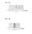
- Figs. 2A and 2B are illustrations for explaining the superposed multicarrier transmission method.
- wireless communication system performing communication using a plurality of nearby frequency bands introduces a guard band between available frequency bands so as to prevent mutual interference therebetween.
- this guard band is unnecessarily used for communication and therefore related to one cause of preventing improvement of frequency availability.
- the transmitter device 10 includes a modulation unit 101, an S/P (serial/parallel) conversion unit 102, a puncture pattern generating unit 103, a puncturing processing unit 104, an IFFT (Inverse Fast Fourier Transform) unit 105, a P/S (parallel/serial) conversion unit 106, and a wireless communication unit 107.
- the modulation unit 101 inputs transmitting bit data, wherein forward error correction (FEC) codes are applied to input bit data so that a modulation symbol, representing the result of modulating bit data subjected to forward error correction coding, is output to the S/P conversion unit 102.
- FEC forward error correction
- the modulation unit 101 may employ convolutional codes, turbo codes or low-density parity check codes (LDPC) in terms of forward error correction codes, while the modulation unit 101 may adopt QPSK (Quadrature Phase Shift Keying), 16QAM (16-position Quadrature Amplitude Modulation) or 64QAM (64-position Quadrature Amplitude Modulation) in terms of modulation.
- FEC forward error correction
- the S/P conversion unit 102 performs serial-parallel conversion on the modulation symbol output from the modulation unit 101, thus outputting the converted symbol to the puncturing processing unit 104.
- the puncture pattern generating unit 103 generates null pattern information representing a sub-carrier allocating Null, designating zero transmitting power, to one of sub-carriers used for communication, so that the generated null pattern information is output to the puncturing processing unit 104.
- the puncturing processing unit 104 changes the modulation symbol, which is designated by the null pattern information output from the puncture pattern generating unit 103 among serial-parallel converted modulation symbols output from the S/P conversion unit 102, with Null designating zero power, which is subsequently forwarded to the IFFT unit 105.
- the IFFT unit 105 converts the modulation symbol output from the puncturing processing unit 104 into a time-domain signal by way of an inverse FFT process, so that the converted signal is forwarded to the P/S conversion unit 106.
- the P/S conversion unit 106 performs parallel-serial conversion on the output signal of the IFFT unit 105, thus outputting the converted signal to the wireless communication unit 107.
- the wireless communication unit 107 coupled with an antenna, performs up-converts a parallel-serial converted signal, output from the P/S conversion unit 106, into a frequency band of a carrier wave, which is subsequently transmitted to the receiver device 20.
- the receiver unit 20 includes a wireless communication unit 201, an S/P conversion unit 202, an FFT (Fast Fourier Transform) unit 203, a P/S conversion unit 204, an interference band detection unit 205, and a demodulation unit 206.
- the wireless communication unit 201 coupled with an antenna receives signals, transmitted by the transmitter device 10, so as to down-convert received signals to ones not having the frequency band of a carrier wave, thus outputting converted signals to the S/P conversion unit 202.
- the S/P conversion unit 202 performs serial-parallel conversion on modulation symbols received by the wireless communication unit 201, thus outputting converted symbols to the FFT unit 203.
- the FFT unit 203 converts serial-parallel converted modulation symbols, output from the S/P conversion unit 202, into frequency-domain modulation symbols by way of an FFT process, thus outputting them to the P/S conversion unit 204.
- the P/S conversions unit 204 performs parallel-serial conversion on converted modulation symbols, output from the FFT unit 203, so as to output them to the interference band detection unit 205 and the modulation unit 206.
- the interference band detection unit 205 stores null pattern information representative of a sub-carrier which is assigned as a null sub-carrier, wherein the interference band detection unit 205 detects the occurrence of an interference wave in the sub-carrier upon detecting a signal power exceeding predetermined reception power from the modulation symbol corresponding to the sub-carrier assigned as the null sub-carrier, thus outputting interference band information representing the sub-carrier, which is deemed susceptible to the interference wave, to the demodulation unit 206.
- the interference band detection unit 205 detects the reception power of the detected interference wave. For instance, the interference band detection unit 205 is able to detect an interference wave upon detecting reception power of a null sub-carrier in response to null pattern information which is selected by a control signal or the like.
- the demodulation unit 206 outputs bit data, which is obtained by way of error correction decoding and demodulation, without using a modulation symbol corresponding to a sub-carrier, which is deemed susceptible to an interference wave based on interference band information output from the interference band detection unit 205, among modulation symbols output from the P/S conversion unit 204.
- the demodulation unit 206 treats a received signal, which is received from a sub-carrier assigned as a null sub-carrier, as an invalid signal, so that error correction decoding and demodulation are performed without using such received signal.
- Fig. 3 is a conceptual illustration representative of transmitting frames demonstrating an example of an allocation of null sub-carriers.
- the horizontal axis represents sub-carrier (frequency) whilst the vertical axis represents time slot (time).
- Each transmitting frame includes ten sub-carriers allocated to different frequencies and further includes four time slots each delimited in a predetermined time interval.
- the puncture pattern generating unit 103 sets null sub-carriers to predetermined sub-carriers (sub-carriers 2, 4, 7, 9) in each transmitting frame.
- the interference band detection unit 205 detects sub-carriers susceptible to the interference wave in accordance with the following procedure.
- the interference band detection unit 205 determines that no interference band occurs in this time slot because high power exceeding a predetermined threshold is not detected from modulation symbols corresponding to null sub-carriers allocated therein.
- the predetermined threshold is statistically or empirically determined upon detecting how much reception power causes an interference wave, wherein this value indicates a power value assuming white noise.
- the interference band detection unit 205 detects a modulation symbol, whose reception power exceeds the predetermined threshold due to the occurrence of an interference wave, in null sub-carrier 9.
- the interference band detection unit 205 estimates the occurrence of an interference wave in sub-carrier 10 because such an interference wave likely occurs in both sides of a communication band owing to an application of a superposed multicarrier transmission method.
- the interference band detection unit 205 determines that the boundary of an interference band may be disposed in sub-carrier 8 or sub-carrier 9, so that the interference band detection unit 205 treats sub-carriers 8-10 as sub-carriers susceptible to the interference wave, thus outputting interference band information to the demodulation unit 206.
- the interference band detection unit 205 may collectively treat sub-carriers 9-10 as an interference band.
- the interference band detection unit 205 detects an interference wave in sub-carrier 9 but does not detect such an interference wave in sub-carrier 7, it is estimated that the boundary of an interference band may be disposed in sub-carrier 8 or sub-carrier 9. This is because, even though the interference band detection unit 205 makes an erroneous determination departing from the actual situation, it is highly likely to precisely detect bit data by way of error correction decoding.
- the interference band detection unit 205 detects an interference band in units of time slots, it is possible to detect an interference band in units of transmitting frames.
- Fig. 4 is a conceptual illustration representative of transmitting frames demonstrating another example of an allocation of null sub-carriers. Similar to Fig. 3 , the horizontal axis represents sub-carrier while the vertical axis represents time slot. Fig. 4 shows that an interference wave occurs in sub-carriers encompassed by a dotted line I2.
- Each transmitting frame includes ten sub-carriers and four time slots.
- the puncture pattern generating unit 103 sets null sub-carriers to predetermined sub-carriers, which are changed in units of time slots.
- the puncture pattern generating unit 103 sets null sub-carriers to sub-carriers 1, 10 in time slot 1; it sets null sub-carriers to sub-carriers 2, 9 in time slot 2; it sets null sub-carriers to sub-carriers 3, 8 in time slot 3; it sets null sub-carriers to sub-carriers 4, 7 in time slot 4.
- the puncture pattern generating unit 103 sequentially arranges null sub-carriers at predetermined positions, which are changed in units of time slots, in a direction from the side ends of a communication frequency band to the center of the communication frequency band.
- the interference band detection unit 205 determines that the boundary of an interference wave may be disposed in sub-carrier 8 in each transmitting frame when the interference band is not greatly varied among transmitting frames, so that the interference band detection unit 205 outputs interference band information, representing that the interference band matches sub-carriers 8-10 in time slots 1-4, to the demodulation unit 206.
- the puncture pattern generating unit 103 sequentially allocates null sub-carriers to time slots in the direction from the side ends to the center of the communication frequency band, thus allowing the interference band detection unit 205 to easily determine which sub-carrier of each transmitting frame is susceptible to an interference wave.
- the wireless communication system adopting the superposed multicarrier transmission method it is possible to improve a tracking ability in detecting a frequency band causing an interference wave.
- Fig. 5 is a conceptual illustration representative of transmitting frames demonstrating a further example of an allocation of null sub-carriers. Similar to Fig. 3 , the horizontal axis represents sub-carrier while the vertical axis represents time slot. Each transmitting frame includes ten sub-carriers and four time slots.
- the puncture pattern generating unit 103 selects and changes sub-carriers, serving as null sub-carriers, in units of time slots.
- the puncture pattern generating unit 103 selects sub-carriers 2, 5, 8 in time slot 1; selects sub-carriers 1, 4, 7, 10 in time slot 2; selects sub-carriers 3, 7, 9 in time slot 3; and selects sub-carriers 2, 5, 8 in time slot 4.
- the puncture pattern generating unit 103 allocates null sub-carriers in a wedge-like formation, it is possible to detect an interference wave over all the sub-carriers in each transmitting frame, wherein it is possible to detect an interference wave occurring in any one of sub-carriers in the communication frequency band.
- the interference band detection unit 205 identifies an interference band, corresponding to a sub-carrier susceptible to the interference wave, based on reception power of a modulation symbol corresponding to a null sub-carrier, thus outputting interference band information, representing the determination result, to the demodulation unit 206.
- the demodulation unit 206 performs error correction decoding and demodulation without using a modulation symbol susceptible to an interference wave or a modulation symbol likely susceptible to an interference wave; hence, it is possible to improve an error correcting ability.
- the present embodiment illustrates three examples for allocating null sub-carriers; however, it is possible to allocate null sub-carriers in other patterns other than the foregoing allocations, or it is possible to allocate them at random.
- the number of null sub-carriers set to each time slot is determined based on a coding ratio of forward error correction coding. Even though some modulation symbols are untransmitted due to the setting of null sub-carriers, it is possible to set a preferred number of null sub-carriers which still allows the receiver device 20 to accurately perform error correction decoding. In this case, it is preferable that the number of null sub-carriers be determined based on characteristics of propagation paths established between the transmitter device 10 and the receiver device 20.
- Fig. 6 is a block diagram showing the overall constitution of a wireless communication system 3 including a transmitter device 12 and a receiver device 22 according to a second embodiment.
- the wireless communication system 3 is constituted of the transmitter device 12 for transmitting data and the receiver device 22 for receiving data from the transmitter device 12. Similar to the wireless communication system 1 of the first embodiment, the wireless communication system 3 adopts an OFDM method demonstrating multicarrier communication; hence, the following description is made with reference to a superposed multicarrier transmission method.
- the transmitter device 12 includes the modulation unit 101, the S/P conversion unit 102, the puncturing processing unit 104, the IFFT unit 105, the P/S conversion unit 106, a wireless communication unit 127, a timer unit 123, and a puncture pattern generating unit 124.
- the transmitter device 12 differs from the transmitter device 10 of the first embodiment in terms of the puncture pattern generating unit 124, the timer unit 123, and the wireless communication unit 127 while other constituent elements are not changed; hence, the foregoing reference numerals (101, 102, 104-106) are used to denote the corresponding parts, and a description thereof will be omitted.
- the timer unit 123 is reset in response to the start timing of transmission of bit data; thereafter, the timer unit 123 counts a predetermined time interval, such as a time interval of one transmitting frame, a time interval of several frames and a real time suited to communication characteristics, wherein upon completion of counting each time interval, the time unit 123 outputs information, representing a lapse of a predetermined time interval, to the puncture pattern generating unit 124, subsequently, the timer unit 123 is reset and starts counting again.
- a predetermined time interval such as a time interval of one transmitting frame, a time interval of several frames and a real time suited to communication characteristics
- the puncture pattern generating unit 124 Similar to the puncture pattern generating unit 103 of the first embodiment, the puncture pattern generating unit 124 generates null pattern information, representing which sub-carrier among sub-carriers used for communication is assigned with Null designating zero transmission power, so as to output the null pattern information to the puncturing processing unit 104, wherein the puncture pattern generating unit 124 further generates null pattern information for setting a null sub-carrier in response to a feedback of interference wave detection information from the reception device 22, thus outputting the null pattern information to the puncturing processing unit 104.
- the wireless communication unit 127 coupled with an antenna up-converts parallel-serial converted signals, output from the P/S conversion unit 106, into ones having a frequency band of a carrier wave, which are subsequently transmitted to the receiver device 22, wherein the wireless communication unit 127 receives interference wave detection information, representing that reception power exceeding the predetermined threshold set to each null sub-carrier is detected, from the receiver device 22, thus forwarding the received interference wave detection information to the puncture pattern generating unit 124.
- the receiver device 22 includes a wireless communication unit 221, the S/P conversion unit 202, the FFT unit 203, the P/S conversion unit 204, an interference band detection unit 225, a timer unit 227, and the demodulation unit 206.
- the receiver device 22 differs from the receiver device 20 of the first embodiment in terms of the wireless communication unit 221 and the interference band detection unit 225, but other constituent elements are not changed; hence, the foregoing reference numerals (202-204, 206) are used to designate the corresponding parts, and a description thereof will be omitted.
- the timer unit 227 operates in synchronization with the timer unit 123 of the transmitter device 12 so that the timer unit 227 is reset in response to the start timing of transmission of bit data; thereafter, the timer unit 227 counts a predetermined time interval, such as a time interval of one transmitting frame, a time interval of several frames, and a real time suited to characteristics of communication, wherein upon completing of counting each time interval, the timer unit 227 outputs timing information, representing a lapse of a predetermined time interval, to the interference band detection unit 225, subsequently, the timer unit 227 is reset and starts counting again. For instance, synchronization between the timer unit 227 and the timer unit 123 can be established using a control signal for starting transmission of bit data.
- the interference band detection unit 225 stores null pattern information, and upon detecting a signal power exceeding the predetermined reception power from a modulation symbol corresponding to a sub-carrier assigned as a null sub-carrier, the interference band detection unit 225 detects the occurrence of an interference wave in the sub-carrier, so that the interference band detection unit 225 outputs interference band information, representing the sub-carrier which is deemed susceptible to an interference wave, to the demodulation unit 206 while detecting reception power of the detected interference wave.
- the interference band detection unit 225 initializes switchover of null pattern information based on timing information output from the timer unit 227.
- the wireless communication unit 221 coupled with an antenna receives signals, transmitted by the transmitter unit 12, so as to down-convert received signals having a frequency band of a carrier wave, thus outputting modulation symbols to the S/P conversion unit 202. Furthermore, the wireless communication unit 221 transmits interference wave detection information, output from the interference wave detection unit 225, in terms of control channels and control signals.
- Fig. 7 is a conceptual illustration representative of transmitting frames demonstrating a further example of an allocation of null sub-carriers in this embodiment.
- an interference band occurs in sub-carriers 8-10 encompassed by a dotted line I3 in time slots 1-4.
- Fig. 8 is a sequence diagram showing the overall operation of the transmitter device 12 and the receiver device 22.
- the timer units 123, 127 are reset upon completion of counting per one transmitting frame.
- the timer unit 123 is reset in response to transmission of bit data (step S11), whilst the timer unit 227 is reset in synchronization with the timer unit 123 (step S12).
- the puncture pattern generating unit 124 When transmission of bit data is started, the puncture pattern generating unit 124 outputs pattern 1, which designates sub-carriers 1, 10 as null sub-carriers, to the puncturing processing unit 104 (step S13).
- the puncturing processing unit 104 sets null sub-carriers in conformity with the input pattern 1 from the puncture pattern generating unit 124, so that a modulation symbol assigned with a null sub-carrier is processed by the IFFT unit 105, the P/S conversion unit 106, and the wireless communication unit 127 in turn; subsequently, a signal of time slot 1 is transmitted to the receiver device 22 (step S14).
- the receiver device 22 receives signals transmitted from the transmitter device 12 with the wireless communication device 221, so that received signals are processed by the S/P conversion unit 202, the FFT unit 203, and the P/S conversion unit 204 in turn; subsequently, processed signals are supplied to the interference band detection unit 225 and the demodulation unit 206.
- the interference band detection unit 225 detects reception power, which exceeds the threshold, from a modulation symbol corresponding to sub-carrier 10 serving as a null sub-carrier (step S15), thus outputting interference wave detection information, representing the occurrence of an interference wave in sub-carrier 10, to the demodulation unit 206 and the wireless communication unit 221.
- the wireless communication unit 221 transmits the interference wave detection information, output from the interference band detection unit 225, to the transmitter device 12 (step S16).
- the wireless communication unit 127 receives the interference wave detection information from the receiver unit 22, so that the received interference wave detection information to the puncture pattern generating unit 124.
- the puncture pattern generating unit 124 allocates a null sub-carrier close to the center frequency of the communication frequency band in order to detect the boundary of an interference band, thus forwarding pattern 2, in which null sub-carriers are set to sub-carriers 3, 8, to the puncturing processing unit 104 (step S17).
- the puncturing processing unit 104 sets null sub-carriers in response to the pattern 2 output from the puncture pattern generating unit 124; the IFFT unit 105 performs an inverse FFT process on a modulation symbol, assigned with a null sub-carrier; the P/S conversion unit 106 performs parallel-serial conversion on the inverse-FFT processed modulation symbol; subsequently, the wireless communication unit 127 transmits the parallel-serial converted modulation symbol to the receiver device 22 (step S18).
- the wireless communication unit 221 receives signals transmitted from the transmitter device 12, so that receives signals are processed by the S/P conversion unit 202, the FFT unit 203, and the P/S conversion unit 204 in turn; subsequently, processed signals are supplied to the interference band detection unit 225 and the demodulation unit 206.
- the interference band detection unit 225 detects reception power, which exceeds the threshold, from a modulation symbol corresponding to sub-carrier 8 serving as a null sub-carrier (step S19), thus outputting interference wave detection information, representing the occurrence of an interference wave in sub-carrier 10, to the demodulation unit 206 and the wireless communication unit 221.
- the wireless communication unit 221 transmits the interference wave detection information, output from the interference band detection unit 225, to the transmitter device 12 (step S20).
- the wireless communication unit 127 receives the interference wave detection information from the receiver device 22, so that the received interference wave detection information is supplied to the puncture pattern generating unit 124.
- the puncture pattern generating unit 124 allocates a null sub-carrier close to the center frequency of the communication frequency band so as to narrow down the search scope of the boundary of an interference band, wherein the puncture pattern generating unit 124 outputs pattern 3, in which null sub-carriers are set to sub-carriers 5, 8 in order to detect the boundary of an interference band, to the puncturing processing unit 104 (step S21).
- the puncturing processing unit 104 sets a null sub-carrier in response to the pattern 3 output from the puncture pattern generating unit 124; the IFFT unit 105 performs an inverse FFT process on a modulation symbol, assigned with a null sub-carrier; the P/S conversion unit 106 performs parallel-serial conversion on the inverse-FFT processed modulation symbol; subsequently, the wireless communication unit 127 transmits the parallel-serial converted modulation symbol to the receiver unit 22 (step S22).
- the wireless communication unit 221 receives signals transmitted from the transmitter device 12, so that received signals are processed by the S/P conversion unit 202, the FFT unit 203, and the P/S conversion unit 204 in turn; subsequently, processed signals are supplied to the interference band detection unit 225 and the demodulation unit 206.
- the interference band detection unit 225 detects reception power, which exceeds the threshold, from a modulation symbol corresponding to sub-carrier 8 serving as a null sub-carrier (step S23), thus outputting interference wave detection information, representing the occurrence of an interference wave in sub-carrier 8, to the demodulation unit 206 and the wireless communication unit 221.
- the wireless communication unit 221 transmits the interference wave detection information, output from the interference band detection unit 225, to the transmitter device 12 (step S24).
- the wireless communication unit 127 receives interference wave detection information from the receiver device 22, so that the received interference wave detection information is supplied to the puncture pattern generating unit 124.
- the puncture pattern generating unit 124 assumes that the boundary of an interference band may be disposed among sub-carriers 6-8, thus outputting pattern 4, in which null sub-carriers are set to sub-carriers 6, 7, to the puncturing processing unit 104 (step S25).
- the puncturing processing unit 104 sets a null sub-carrier in response to the pattern 4 output from the puncture pattern generating unit 124; the IFFT unit 105 performs an inverse FFT process on a modulation symbol, assigned with a null sub-carrier; the P/S conversion unit 106 performs parallel-serial conversion on the inverse-FFT processed modulation symbol; subsequently, the wireless communication unit 127 transmits the parallel-serial converted modulation symbol to the receiver device 22 (step S26).
- the wireless communication unit 221 receives signals transmitted from the transmitter device 12, so that receives signals are processed by the S/P conversion unit 202, the FFT unit 203, and the P/S conversion unit 204 in turn; subsequently, processed signals are supplied to the interference band detection unit 225 and the demodulation unit 206.
- the interference band detection unit 225 does not detect reception power, which exceeds the threshold, from a modulation symbol corresponding to sub-carriers 6, 7, which serve as null sub-carriers (step S27), thus outputting interference wave detection information, representing that an interference wave does not exist in sub-carrier 8, to the demodulation unit 206 and the wireless communication unit 221.
- the wireless communication unit 221 transmits the interference wave detection information, output from the interference band detection unit 225, to the transmitter device 12 (step S28).
- the timer unit 123 Upon completion of transmitting four time slots per one transmitting frame, the timer unit 123 completes counting so as to notify the puncture pattern generating unit 124 of completion of transmitting one transmitting frame (step S29).
- the transmitting device 12 operates similarly in accordance with the foregoing steps, wherein determination as to which sub-carrier is set to a null sub-carrier depends on each sub-carrier in which an interference wave is detected.
- the timer unit 227 completes counting so as to notify the interference band detection unit 225 of completion of transmitting one transmitting frame (step S29a).
- the interference band detection unit 225 determines that the boundary of an interference band may be disposed in sub-carrier 8, thus outputting interference band detection information, representing that an interference band overlaps sub-carriers 8-10, to the demodulation unit 206 (step S30).
- the demodulation unit 206 performs error correction decoding and demodulation so as to detect bit data without using modulation symbols corresponding to sub-carriers 8-10 in time slots 1-4 (step S31).
- the interference band detection unit 225 of the receiver device 22 feeds back the information, representative of the detected interference wave, to the puncture pattern generating unit 124 of the transmitter device 12; hence, it is possible to efficiently specify an interference band.
- the puncture pattern generating unit 124 allocates a large number of null sub-carriers; this makes it possible to detect the boundary of an interference band with a small number of times for detecting an interference wave.
- the first embodiment and the second embodiment are configured to perform error correction decoding and demodulation by means of the demodulation unit 206 without using modulation symbols susceptible to an interference wave, whereas those modulation symbols can be multiplied by weights and treated as insignificant modulation symbols, whose reliability is lower than modulation symbols corresponding to sub-carriers not susceptible to an interference wave, so that error correction decoding and demodulation can be performed using those modulation symbols.
- the operation not using modulation symbols corresponding to sub-carriers susceptible to an interference wave can be achieved by setting zero reliability to those modulation symbols.
- weight coefficients can be set to fixed values and varied in response to reception power of the detected interference wave.
- a receiver device can dynamically determine whether or not the current situation is regarded as the environment undergoing the frequent occurrence of interference waves; subsequently, the result of the determination is fed back to a transmitter device.
- the first embodiment and the second embodiment are configured such that the interference band detection units 205, 225 store sub-carriers serving as null sub-carriers, whilst the transmitter devices 10, 11, 12 can be redesigned to transmit control signals incorporating null pattern information representing sub-carriers serving as null sub-carriers.
- the null pattern information for setting null sub-carriers can be produced based on reception power of interference waves detected by the interference band detection units 205, 225.
- the process for setting null sub-carriers and the process for detecting an interference band are written in programs and stored in computer-readable storage media, wherein computer systems read and execute programs so as to implement these processes.
- computer-readable storage media refer to magnetic disks, magneto-optical disks, CD-ROM, DVD-ROM, semiconductor memory or the like.
- Computer programs can be distributed to computer systems via communication lines, so that computer systems can implement programs distributed thereto.
- Fig. 9 is an illustration showing the overview constitution of a wireless communication system 5 according to a third embodiment, which transmits/receives signals by way of multicarrier transmission.
- the wireless communication system 5 is a wireless communication system of this invention, which includes a transmitter device 50 and a receiver device 60.
- the number of the transmitter device 50 and the receiver device 60 included in the wireless communication system 5 is necessarily limited to one as shown in Fig. 9 ; hence, it is possible to incorporate plural devices.
- the transmitter device 50 serves as a base station device whilst the receiver device 60 serves as a wireless communication terminal; however, the transmitter device 50 may serve as a wireless communication terminal while the receiver device 60 may serve as a base station device.
- the wireless communication terminal is a terminal device that is able to perform wireless communication with the base station device, wherein the wireless communication terminal exemplarily refers to a wireless LAN (Local Area Network) terminal, a WiMAX (a registered trademark) (Worldwide Interoperability for Microwave Access) terminal or the like.
- the base station device is a device that is able to perform wireless communication with a plurality of wireless communication terminal, wherein the base station device exemplarily refers to a base station device in a portable telephone network, a wireless LAN router, a WiMAX (a registered trademark) base station or the like.
- the transmitter device 50 and the receiver device 60 perform wireless communication by way of a multicarrier transmission method. Specifically, the transmitter device 50 and the receiver device 60 perform wireless communication by way of OFDM (Orthogonal Frequency Division Multiplexing).
- OFDM Orthogonal Frequency Division Multiplexing
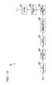
- Fig. 10 is a block diagram showing the functional constitution of the transmitter device 50 of this embodiment.
- the transmitter device 50 includes an FEC coding unit 504, a first modulation unit 502, a block coding unit 503, a serial-parallel conversion unit 504, a second modulation unit 505, a transmission unit 506, and an antenna 507.
- the FEC coding unit 501 performs error correction coding on bit strings of transmitting data according to the FEC (Forward Error Correction), thus generating error-correction coded bits.
- FEC Forward Error Correction
- the first modulation unit 502 performs a modulation process (a mapping process) on error-correction coded bits, thus generating a plurality of modulation symbols.
- the first modulation unit 502 performs a modulation process according to BPSK (Binary Phase Shift Keying), QPSK (Quadrature Phase Shift Keying), or 8 PSK (Octuple Phase Shift Keying), for example, thus generating combinations (modulation symbols) of amplitude values and phase values based on error-correction coded bits.
- the block coding unit 503 performs a block coding process on modulation symbols generated by the first modulation unit 502.
- the block coding unit 503 adopts a block coding method which allows for reversible calculation (block decoding) and by which a part of block-coded signals becomes zero in amplitude.
- the block coding unit 503 performs a block coding process using Hadamard matrix of Equation 1, which is one type of orthogonal matrix.
- Equation 1 , d 2 denote modulation symbols
- b 1 , b 2 denote modulation symbols after completion of block coding (block-coded modulation symbols).
- the block coding unit 503 does not necessarily use Hadamard matrix but use M-series or scramble codes.
- b 1 b 2 1 1 1 - 1 ⁇ d 1 d 2
- Fig. 11 is an illustration showing the occurrence probability of constellation points after block coding, wherein the vertical axis Q represents orthogonal elements, and the horizontal axis I represents common-mode elements.
- Fig. 11 shows an example in which modulation symbols modulated with isoelectric power QPSK (four constellation points) are subjected to block coding using 2x2 Hadamard matrix. In this case, there are sixteen combinations of modulation symbols d 1 , d 2 .
- there are nine types of constellation points with respect to block-coded modulation symbols b 1 , b 2 among which the occurrence probability of constellation points (0,0) demonstrating zero amplitude is 25%.
- the serial-parallel conversion unit 504 performs serial-parallel conversion on a plurality of block-coded modulation symbols generated by the block coding unit 503.
- the second modulation unit 505 allocates block-coded modulation symbols, which are cascaded by the serial-parallel conversion unit 504, to sub-carriers, wherein the second modulation unit 505 generates modulation signals by way of IFFT (Inverse Fast Fourier Transform), parallel-serial conversion and guard-interval insertion.
- IFFT Inverse Fast Fourier Transform
- the transmission unit 506 performs digital-analog conversion, power amplification and up-conversion on modulation signals, thus generating transmitting signals.
- the antenna 507 transmits transmitting signals, generated by the transmission unit 506, via wireless transmission.
- Figs. 12A and 12B are illustrations representative of transmitting signals.
- the horizontal axis represents frequency, and the vertical axis represents amplitude.
- Fig. 12A shows transmitting signals generated according to the foregoing multicarrier method (QPSK modulation, OFDM), while Fig. 12B shows transmitting signals generated by the transmitter device 50.
- QPSK modulation OFDM
- an amplitude a1 is uniformly applied to a plurality of sub-carriers, which do not include sub-carriers having zero amplitude (hereinafter, those sub-carriers will be referred to as "null sub-carriers").
- Fig. 12B shows the coexistence of sub-carriers having a relatively large amplitude a2, sub-carriers having a relatively small amplitude a1, and null sub-carriers having zero amplitude.
- null sub-carriers are disposed in frequency bands denoted by upward arrows so that those sub-carriers are allocated with block-coded modulation symbols whose amplitudes become zero via the block coding unit 503.
- FIG. 13 is a flowchart showing a transmitting procedure of the transmitter device 50.
- the FEC coding unit 501 performs error correction coding on bit strings of transmitting data in accordance with the FEC procedure, thus generating error-correction coded bits (step S101).
- the first modulation unit 502 modulates error-correction coded bits so as to generate modulation symbols (step S102).
- the block coding unit 503 performs a block coding process on modulation symbols modulation symbols (step S103).
- the serial-parallel conversion unit 504 performs serial-parallel conversion on block-coded modulation symbols (step S104).
- the second modulation unit 505 performs an IFFT procedure (step S105), thus achieving parallel-serial conversion and guard-interval insertion (step S106).
- the transmission unit 506 generates transmitting signals (step S107). Subsequently, the antenna 507 transmits signals via wireless transmission (step S108), thus completing the transmitting procedure shown in this flowchart.
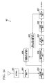
- Fig. 14 is a block diagram showing the functional constitution of the receiver device 60 in this embodiment.
- the receiver device 60 includes an antenna 601, a reception unit 602, a second modulation unit 603, a parallel-serial conversion unit 604, a block decoding unit 605, a first demodulation unit 606, an FEC decoding unit 607, a null sub-carrier determination unit 608, and an interference signal detection unit 609.
- the antenna 601 receives signals combining signals transmitted by the transmitter device 50 and interference signals transmitted by another transmitter device.
- the reception unit 602 performs down-conversion and analog-digital conversion on received signals, thus generating modulation signals.
- the second modulation unit 603 performs guard-interval removal, serial-parallel conversion, FFT (Fast Fourier Transform), and frequency-domain equalization using preamble information on modulation signals, thus generating a plurality of block-coded modulation symbols.
- FFT Fast Fourier Transform
- the parallel-serial conversion unit 604 performs parallel-serial conversion on a plurality of block-coded modulation symbols which are cascaded to each other.
- the block decoding unit 605 performs a block decoding process, which is commensurate to a block coding process of the block coding unit 503 of the transmitter device 50, on block-coded modulation symbols, thus reproducing modulation symbols.
- the block coding unit 503 performs a block coding process using a Hadamard matrix according to Equation 1
- the block decoding unit 605 performs a block decoding process using an inverse matrix of a Hadamard matrix according to Equation 2.
- d 1 d 2 1 1 1 - 1 - 1 b 1 b 2
- the first demodulation unit 606 performs demodulation (de-mapping process), which is commensurate to modulation of the first modulation unit 502 of the transmitter device 50, on modulation symbols, thus generating error-correction coded bits.
- the FEC decoding unit 607 performs error correction and decoding on error-correction coded bits by way of FEC, thus reproducing original data subjected to transmission.
- the null sub-carrier determination unit 608 identifies frequency bands allocating null sub-carriers in transmitting signals. Specifically, the null sub-carrier determination unit 608 performs processing, similar to the processing implemented by the FEC coding unit 501, the first modulation unit 502 and the block coding unit 503 of the transmitter device 50, on output data of the FEC decoding unit 607, thus generating replica signals and identifying frequency bands (hereinafter, referred to as "null frequency bands") allocated to null sub-carriers.
- the interference signal detection unit 609 measures signal components of null frequency bands from received signals, thus detecting interference signals. For instance, the interference signal detection unit 609 measures amplitudes of signal components of null sub-carriers from received signals, wherein the interference signal detection unit 609 detects the occurrence of an interference signal in each null frequency band when the measurement result is higher than a predetermined threshold. In addition, the interference signal detection unit 609 may store detection result, indicating the occurrence/absence of a interference signal in each null frequency band and an amplitude of a detected interference signal, in connection with each frequency band. In this case, upon retrieving detection results with respect to all the frequency bands in signals received by the receiver device 60, the interference signal detection unit 609 may output detection results of frequency bands, which are stored, as detection results of interference signals.
- FIG. 15 is a flowchart showing the receiving procedure of the receiver device 60.
- the antenna 601 receives signals (step S201), so that the reception unit 602 reproduces modulation signals from received signals (step S202).
- the second demodulation unit 603 performs guard-interval removal and serial-parallel conversion on modulation signals (step S203).
- the second demodulation unit 603 generates block-coded modulation symbols by way of FFT (step S204).
- the parallel-serial conversion unit 604 performs parallel-serial conversion on block-coded modulation symbols (step S205).
- the block decoding unit 605 performs block decoding on block-coded modulation symbols, thus reproducing modulation symbols (step S206).
- the first demodulation unit 606 demodulates modulation symbols so as to generate error-correction coded bits (step S207).
- the FEC decoding unit 607 performs error correction decoding on error-correction coded bits, thus reproducing original data subjected to transmission (step S208).
- the null sub-carrier determination unit 608 generates replica signals (step S209) so as to identify null frequency bands (step S210).
- the interference signal detection unit 609 detects an interference signal in each null frequency band (step S211).
- the wireless communication system 5 is configured such that the block coding unit 503 of the transmitter device 50 performs a block coding process, it is unnecessary to deliberately incorporate null sub-carriers not including transmitting data, but it is possible to generate null sub-carriers incorporating a part of transmitting data in transmitting signals. For this reason, it is possible to generate transmitting signals having null sub-carriers without reducing the amount of data included in transmitting signals. Therefore, the receiver device 60 identifies frequency bands of null sub-carriers (null frequency bands) so as to measure signals in those frequency bands; thus, it is possible to precisely detect interference signals while preventing degradation of data transmission efficiency.
- null sub-carriers null frequency bands
- the receiver device 60 is allowed to detect and measure interference signals in null frequency bands alone.
- frequency bands of null sub-carriers which occur in transmitting signals are not fixed but are varied for each transmitting signal; hence, the receiver device 60 needs to receive transmitting signals multiple times and detect interference signals, whereby it is possible to detect interference signals in the entire frequency range used in the wireless communication system 5 and the receiver device 60.
- the conventional technology which measures interference signals by use of non-transmission intervals of burst transmission or null signal intervals deliberately interposed in data intervals, suffers from a problem due to a bad tracking ability in reacting to fluctuations of characteristics of transmission paths due to intermittently implemented measurement on interference signals.
- the wireless communication system 5 is configured such that the transmitter device 50 normally performs a block coding process so as to generate transmitting signals, thus improving a tracking ability in reacting to fluctuating characteristics of transmission paths.
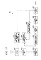
- Figs. 16 and 17 are block diagrams showing the functional constitutions of the transmitter device 50 and the receiver device 60 included in the wireless communication system 5 according to a variation of the third embodiment.
- the transmitter device 50 can be redesigned to further include an interference band information signal reception unit 508.
- the receiver device 60 can be redesigned to further include an interference band information signal transmission unit 610.
- the transmitter device 50 receives interference band information transmitted by the receiver device 60 so as to operate based on the interference band information.
- the transmitter device 50 and the receiver device 60 having the above constitutions will be described.
- the interference band information signal transmission unit 610 generates interference band information based on the detection result of the interference signal detection unit 609.
- the interference band information is information regarding an interference signal which occurs during wireless communication between the transmitter device 50 and the receiver device 60.
- the interference band information is information representative of sub-carriers already undergoing interference or information representative of amplitude of an interference signal.
- the interference band information may include information of an error ratio calculated in error correction decoding of the FEC decoding unit 607.
- the interference band information signal transmission unit 610 performs error correction coding, modulation, digital-analog conversion and up-conversion on the interference band information so as to generate wireless signals (interference band information signals), which are subsequently transmitted to the transmitter device 50 via the antenna 601.
- the interference band information signal reception unit 508 performs down-conversion, analog-digital conversion, demodulation and error correction decoding on interference band information signals, which are received by the antenna 507, thus retrieving interference band information from interference band information signals.
- the FEC coding unit 501 performs adaptive modulation based on an error ratio included in interference band information, thus changing a coding ratio thereof.
- the adaptive modulation can be implemented using the existing technology. For instance, the FEC coding unit 501 decreases a coding ratio thereof to be lower than the currently applied coding ratio so as to increase resistance to interference when the error ratio is high, whilst the FEC coding unit 501 increases a coding ratio thereof to be higher than the currently applied coding ratio so as to decrease resistance to interference when the error ratio is low.
- the first modulation unit 502 performs adaptive modulation based on an error ratio included in interference band information, thus generating a plurality of modulation symbols.
- the adaptive modulation can be implemented using the existing technology. For instance, the first modulation unit 502 generates modulation symbols in accordance with a modulation method having a high resistance to interference, whose multi-valued degree of modulation is lower than the currently applied modulation method, when the error ratio is high, whilst the first modulation unit 502 generates modulation symbols in accordance with a modulation method having a low resistance to interference, whose multi-valued degree of modulation is higher than the currently applied modulation method, when the error ratio is low.
- the transmitter device 50 does not deliberately interpose sub-carriers having zero amplitude which do no include transmitting data but generates sub-carriers having zero amplitude which share a part of transmitting data.
- the receiver device 60 detects interference signals, which are commensurate to signals having frequency bands of sub-carriers having zero amplitude in the transmitter device 50, from received signals. For this reason, this invention is able to detect interference signals while preventing degradation of data transmission efficiency.
- detection result of interference signals in the receiver device 60 is used to generate interference band information signals which are sent to the transmitter device 50, whereas detection result of interference signals is not necessarily limited to this utilization and therefore can be applied to other utilizations.
- the receiver device 60 can be reconfigured to perform demodulation in response to interference signals by feeding back detection result of interference signals to the second demodulation unit 603, thus improving a demodulation precision.
Landscapes
- Engineering & Computer Science (AREA)
- Signal Processing (AREA)
- Computer Networks & Wireless Communication (AREA)
- Quality & Reliability (AREA)
- Physics & Mathematics (AREA)
- Spectroscopy & Molecular Physics (AREA)
- General Health & Medical Sciences (AREA)
- Health & Medical Sciences (AREA)
- Power Engineering (AREA)
- Probability & Statistics with Applications (AREA)
- Theoretical Computer Science (AREA)
- Mobile Radio Communication Systems (AREA)
- Detection And Prevention Of Errors In Transmission (AREA)
Abstract
Description
- This invention relates to wireless communication systems and wireless communication methods.
- Recently, starvation of limited frequency resources has been a serious problem in the field of wireless communication; hence, it is expected to improve frequency availability. Frequency sharing wireless communication may serve as a technology for improving frequency availability.
Fig. 18 is a conceptual illustration showing the overall system constitution including two wireless LANs (Local Area Network) using different frequency channels, which is one example of a combination of wireless communication systems sharing frequency bands. - The illustrated wireless communication system includes wireless
LAN base stations receiver device 20a. The wirelessLAN base station 10a performs communication using a frequency band of a channel CH1 with a center frequency fa. The wireless LAN base station performs communication using the frequency band of a channel CH5 with a center frequency fb (fa<fb). - The
receiver device 20a is located at a position reachable by both of the wireless signals of the wirelessLAN base stations receiver device 20a may receive signals in which wireless signals having the center frequency fa partially interfere with wireless signals having the center frequency fb. - As another example of the technology sharing frequency bands, it is possible to present a wireless LAN system combined with a Bluetooth system (registered trademark) and a WiMAX system (registered trademark); hence, it may be possible to combine different communication systems which share frequencies.
- During communication with the wireless
LAN base station 10a, for example, a transmitting frequency band of a preferred signal having the center frequency fa partially overlaps (interferes) with a transmitting frequency band of an interference signal having the center frequency fb output from the wirelessLAN base station 10b. In this frequency shared wireless communication, thereceiver device 20a needs to improve frequency availability by efficiently performing error correction; hence, it is necessary to precisely detect the occurrence of an interference signal overlapped with the frequency band of a preferred signal. - As a technology for detecting the occurrence of an interference signal, a technology for measuring an interference signal by use of a pattern-known signal such as a training signal and a sounding signal has been developed (see Patent Document 1). Another technology for measuring an interference signal by use of a non-transmission interval of burst transmission or a null signal interval deliberately interposed in a data interval has been developed as well.
- Patent Document 1: Japanese Patent Application Publication No.
2007-282120 JP 2007 312114A - Document
WO 2008/0997885 A1 - However, the foregoing technologies for detecting interference signals may degrade data transmitting efficiency or suffer from a problem due to low tracking with varying transmission lines.
- Considering these circumstances, this invention is intended for the purpose of providing a wireless communication system and a wireless communication method which are able to detect interference signals while preventing degradation of data transmitting efficiency.
-
- [1] A first aspect of this invention demonstrates a wireless communication system performing wireless communication between a transmitter device and a receiver device according to a multicarrier multiplexing transmission method, wherein
said transmitter device is adapted to perform error correction coding on transmitting data and to randomly set a plurality of null subcarriers, having zero amplitude according to a predetermined null pattern in order to determine whether an interference wave occurs among a plurality of subcarriers which are allocated to transmission of data, subjected to error correction coding, said transmitter device is adapted to configure each transmission frame set for each time slot, thus transmitting all the data of the error correction coding via the plurality of subcarriers without decreasing data transmission efficiency, while said receiver device is adapted to perform error-correction decoding on received signals from the transmitter device so as to reproduce the transmitting data, wherein upon detecting reception power exceeding a threshold within the plurality of null subcarriers for each transmission frame, said receiver device determines that an interference wave occurs in the transmission frame, said receiver device is further adapted to determine occurrence of an interference wave detection information, representing at least one sub-carrier undergoing interference being detected, thus having the transmitter device set the plurality of null sub-carrier being disposed based on the interference wave detection information. - [2] Another aspect of this invention demonstrates the wireless communication system, in which each sub-carrier serving as a null sub-carrier is changed in each time slot delimited by a predetermined time interval.
- [3] A further aspect of this invention demonstrates the wireless communication system, wherein it is determined which one or more sub-carriers among the plurality of sub-carriers are selected as the null sub-carrier in advance.
- [4] A further aspect of this invention demonstrates the wireless communication system, in which null sub-carriers are allocated in an order counting from a sub-carrier having a highest frequency to a sub-carrier having a center frequency among the plurality of sub-carriers; alternatively, null sub-carriers are allocated in an order counting from a sub-carrier having a lowest frequency to the sub-carrier having the center frequency among the plurality of sub-carriers.
- [5] A further aspect of this invention demonstrates the wireless communication system, in which one of the plurality of sub-carriers is randomly selected as a null sub-carrier.
- [6] A further aspect of this invention demonstrates the wireless communication system, in which the number of null sub-carriers selected from among the plurality of sub-carriers is determined based on a coding ratio of forward error coding or characteristics of a transmission path established between the transmitter device and the receiver device.
- [7] A further aspect of this invention demonstrates the wireless communication system, wherein the receiver device transmits interference wave detection information, representing the sub-carrier in which an interference wave is detected, to the transmitter device, whilst the transmitter device sets the null sub-carrier based on the interference wave detection information transmitted thereto.
- [8] A further aspect of this invention demonstrates the wireless communication system, wherein the receiver device makes an estimate, based on the interference wave detection information during consecutive time slots, as to which sub-carrier among the plurality of sub-carriers undergoes an interference wave in any one of the consecutive time slots, so that the receiver device demodulates transmitted data without using a modulation symbol assigned to the sub-carrier undergoing the interference wave.
- [9] A further aspect of this invention demonstrates the wireless communication system, wherein the transmitter device includes a modulation unit, adopting forward error correction coding on transmitting data, which modulates forward error-correction coded transmitting data so as to output modulation signals, and a puncturing processing unit which applies zero transmission power to a modulation signal, which is assigned to the sub-carrier serving as the null sub-carrier among the plurality of sub-carriers, among the modulation signals output from the modulation unit.
- [10] A further aspect of this invention demonstrates the wireless communication system, in which the receiver device discards a received signal, corresponding to the sub-carrier serving as the null sub-carrier, as an invalid signal, thus performing demodulation and error correction decoding without using the received signal.
- [11] A further aspect of this invention demonstrates the wireless communication system, wherein the transmitter device includes an error correction coding unit that performs error correction coding on transmitting data so as to generate error-correction coded bits; a first modulation unit that modulates error-correction coded bits so as to generate a plurality of modulation symbols; a block coding unit that performs block coding on the plurality of modulation symbols, a part of which becomes zero in amplitude; a second modulation unit that allocates block-coded modulation symbols to sub-carriers so as to generate modulation signals; and a transmission unit that generates and outputs transmitting signals based on modulation signals, whilst the receiver device includes a reception unit that receives signals transmitted thereto; a second demodulation unit that retrieves modulation symbols, which are subjected to block coding in units of sub-carries, from received signals; a block decoding unit that performs block decoding, which is commensurate to block coding of the block coding unit, on block-coded modulation symbols; a first demodulation unit that performs demodulation, which is commensurate to modulation of the first modulation unit, on block-decoded modulation symbols; an error correction decoding unit that performs error correction and decoding, which is commensurate to the error correction coding of the error correction coding unit, by use of demodulated values, thus reproducing original data subjected to transmission; a decision unit that identifies a frequency band of the sub-carrier having zero amplitude in transmitting signals generated by the transmission unit based on transmitted data; and a detection unit that detects an interference signal representative of a signal having the frequency band of the sub-carrier having zero amplitude, identified by the decision unit, among received signals transmitted thereto, wherein the receiver device transmits interference wave detection information, representing the sub-carrier in which an interference wave is detected, to the transmitter device, whilst the transmitter device sets the null sub-carrier based on the interference wave detection information transmitted thereto.
- [12] A further aspect of this invention demonstrates the wireless communication system, wherein the decision unit performs error correction coding which is identical to the error correction coding of the error correction coding unit, performs modulation which is identical to the modulation of the first modulation unit, and performs the block coding which is identical to the block coding of the block coding unit on transmitted data, thus identifying the frequency band of the sub-carrier having zero amplitude among transmitting signals generated by the transmission unit.
- [13] A further aspect of this invention demonstrates the wireless communication system, wherein the receiver device further includes an interference band information signal transmission unit that generates interference band information representative of the sub-carrier undergoing an interference wave based on the detected interference signal so as to transmit the interference band information to the transmitter device, and wherein the first modulation unit or the error correction coding unit of the transmitter device determines a modulation method or a coding ratio based on the interference band information.
- [14] A further aspect of this invention demonstrates a wireless communication method which is adapted to a wireless communication system including a transmitter device and a receiver device used for transmission of wireless signals including a plurality of sub-carriers and which is characterized by implementing a procedure in which the transmitter device performs error correction coding on transmitting data and sets a null sub-carrier having zero amplitude representative of at least one of the plurality of sub-carriers used for transmission of error-correction coded data, thus transmitting the error-correction coded data, and a procedure in which the receiver device receives signals having the plurality of sub-carriers from the transmitter device so as to retrieve original transmitted data by implementing error correction decoding on received signals, thus determining whether an interference wave occurs in the sub-carrier upon detecting reception power exceeding a predetermined threshold in the sub-carrier serving as the null sub-carrier.
- In this invention, after implementation of error correction coding on transmitting data, a transmitter device transmits a null sub-carrier having zero amplitude representing a part of a sub-carrier for transmitting data with error correcting codes. A receiver device detects an interference signal, representing a signal having a null sub-carrier frequency band, from received signals while performing error correction decoding so as to decode transmitted data. Since this invention is able to generate a null sub-carrier without the addition of more data, exclusively used for generating a null sub-carrier, to transmitting data, it is possible to detect an interference signal without degrading the data transmitting efficiency.
-
- [
Fig. 1 ] A block diagram showing the overview constitution of a wireless communication system according to a first embodiment including a transmitter device and a receiver device. - [
Fig. 2A ] A conceptual illustration representative of superposed multicarrier transmission. - [
Fig. 2B ] A conceptual illustration representative of superposed multicarrier transmission. - [
Fig. 3 ] A conceptual illustration representative of transmitting frames demonstrating an example of an allocation of null sub-carriers according to the first embodiment. - [
Fig. 4 ] A conceptual illustration representative of transmitting frames demonstrating another example of an allocation of null sub-carriers according to the first embodiment. - [
Fig. 5 ] A conceptual illustration representative of transmitting frames demonstrating a further example of an allocation of null sub-carriers according to the first embodiment. - [
Fig. 6 ] A block diagram showing the overview constitution of a wireless communication system including a transmitter device and a receiver device according to a second embodiment. - [
Fig. 7 ] A conceptual illustration representative of transmitting frames demonstrating an example of a allocation of null sub-carriers according to the second embodiment. - [
Fig. 8 ] A sequence diagram illustrating the operation of the transmitter device and the receiver device according to the second embodiment. - [
Fig. 9 ] An illustration showing the overview constitution of a wireless communication system according to a third embodiment, which performs transmission/reception of signals by way of multicarrier transmission. - [
Fig. 10 ] A block diagram showing the functional constitution of the transmitter device according to the third embodiment. - [
Fig. 11 ] An illustration showing an occurrence probability of constellation points after completion of block coding according to the third embodiment. - [
Fig. 12A ] An illustration representative of transmitting signals. - [
Fig. 12B ] An illustration representative of transmitting signals. - [
Fig. 13 ] A flowchart illustrating a transmitting procedure of the transmitter device according to the third embodiment. - [
Fig. 14 ] A block diagram showing the functional constitution of the receiver device according to the third embodiment. - [
Fig. 15 ] A flowchart illustrating a receiving procedure of the receiver device according to the third embodiment. - [
Fig. 16 ] A block diagram showing the functional constitution of a transmitter device according to a variation of the third embodiment. - [
Fig. 17 ] A block diagram showing the functional constitution of a receiver device according to a variation of the third embodiment. - [
Fig. 18 ] A conceptual illustration showing the overall system constitution, which is one example of a combination of wireless communication systems sharing frequency bands. - Hereinafter, wireless communication systems according to various embodiments of this invention will be described with reference to the drawings.
-
Fig. 1 is a block diagram showing the constitution of awireless communication system 1 including atransmitter device 10 and areceiver device 20. Thewireless communication system 1 is constituted of thetransmitter device 10 for transmitting data and thereceiver device 20 for receiving data from thetransmitter device 10. - The
wireless communication system 1 of this embodiment adopts an OFDM (Orthogonal Frequency Division Multiplexing) method achieving multicarrier communication; hence, the following description refers to an application of a superposed multicarrier transmission method. - The superposed multicarrier transmission method is a name of one technology for improving frequency availability.
Figs. 2A and 2B are illustrations for explaining the superposed multicarrier transmission method. Generally speaking, as shown inFig. 2A , wireless communication system performing communication using a plurality of nearby frequency bands introduces a guard band between available frequency bands so as to prevent mutual interference therebetween. - However, this guard band is unnecessarily used for communication and therefore related to one cause of preventing improvement of frequency availability.
- This drawback can be solved by not using guard bands as shown in
Fig. 2B in which frequency bands are partially superposed on each other during communication implemented on the precondition that various signals mutually interfere with each other, wherein upon detecting the occurrence of mutual interference, error correction decoding is performed using signals not susceptible to mutual interference, thus reducing frequency bands occupied by the wireless communication system and thereby improving frequency availability. - Referring back to
Fig. 1 , thetransmitter device 10 and thereceiver device 20 will be described. - The
transmitter device 10 includes amodulation unit 101, an S/P (serial/parallel)conversion unit 102, a puncturepattern generating unit 103, a puncturingprocessing unit 104, an IFFT (Inverse Fast Fourier Transform)unit 105, a P/S (parallel/serial)conversion unit 106, and awireless communication unit 107. - The
modulation unit 101 inputs transmitting bit data, wherein forward error correction (FEC) codes are applied to input bit data so that a modulation symbol, representing the result of modulating bit data subjected to forward error correction coding, is output to the S/P conversion unit 102. For instance, themodulation unit 101 may employ convolutional codes, turbo codes or low-density parity check codes (LDPC) in terms of forward error correction codes, while themodulation unit 101 may adopt QPSK (Quadrature Phase Shift Keying), 16QAM (16-position Quadrature Amplitude Modulation) or 64QAM (64-position Quadrature Amplitude Modulation) in terms of modulation. - The S/
P conversion unit 102 performs serial-parallel conversion on the modulation symbol output from themodulation unit 101, thus outputting the converted symbol to thepuncturing processing unit 104. The puncturepattern generating unit 103 generates null pattern information representing a sub-carrier allocating Null, designating zero transmitting power, to one of sub-carriers used for communication, so that the generated null pattern information is output to thepuncturing processing unit 104. The puncturingprocessing unit 104 changes the modulation symbol, which is designated by the null pattern information output from the puncturepattern generating unit 103 among serial-parallel converted modulation symbols output from the S/P conversion unit 102, with Null designating zero power, which is subsequently forwarded to theIFFT unit 105. - The
IFFT unit 105 converts the modulation symbol output from the puncturingprocessing unit 104 into a time-domain signal by way of an inverse FFT process, so that the converted signal is forwarded to the P/S conversion unit 106. - The P/
S conversion unit 106 performs parallel-serial conversion on the output signal of theIFFT unit 105, thus outputting the converted signal to thewireless communication unit 107. Thewireless communication unit 107, coupled with an antenna, performs up-converts a parallel-serial converted signal, output from the P/S conversion unit 106, into a frequency band of a carrier wave, which is subsequently transmitted to thereceiver device 20. - The
receiver unit 20 includes awireless communication unit 201, an S/P conversion unit 202, an FFT (Fast Fourier Transform)unit 203, a P/S conversion unit 204, an interferenceband detection unit 205, and ademodulation unit 206. Thewireless communication unit 201 coupled with an antenna receives signals, transmitted by thetransmitter device 10, so as to down-convert received signals to ones not having the frequency band of a carrier wave, thus outputting converted signals to the S/P conversion unit 202. - The S/
P conversion unit 202 performs serial-parallel conversion on modulation symbols received by thewireless communication unit 201, thus outputting converted symbols to theFFT unit 203. TheFFT unit 203 converts serial-parallel converted modulation symbols, output from the S/P conversion unit 202, into frequency-domain modulation symbols by way of an FFT process, thus outputting them to the P/S conversion unit 204. - The P/
S conversions unit 204 performs parallel-serial conversion on converted modulation symbols, output from theFFT unit 203, so as to output them to the interferenceband detection unit 205 and themodulation unit 206. The interferenceband detection unit 205 stores null pattern information representative of a sub-carrier which is assigned as a null sub-carrier, wherein the interferenceband detection unit 205 detects the occurrence of an interference wave in the sub-carrier upon detecting a signal power exceeding predetermined reception power from the modulation symbol corresponding to the sub-carrier assigned as the null sub-carrier, thus outputting interference band information representing the sub-carrier, which is deemed susceptible to the interference wave, to thedemodulation unit 206. The interferenceband detection unit 205 detects the reception power of the detected interference wave. For instance, the interferenceband detection unit 205 is able to detect an interference wave upon detecting reception power of a null sub-carrier in response to null pattern information which is selected by a control signal or the like. - The
demodulation unit 206 outputs bit data, which is obtained by way of error correction decoding and demodulation, without using a modulation symbol corresponding to a sub-carrier, which is deemed susceptible to an interference wave based on interference band information output from the interferenceband detection unit 205, among modulation symbols output from the P/S conversion unit 204. In addition, thedemodulation unit 206 treats a received signal, which is received from a sub-carrier assigned as a null sub-carrier, as an invalid signal, so that error correction decoding and demodulation are performed without using such received signal. - Next, the setting of a null sub-carrier and the detection of an interference wave will be described.
-
Fig. 3 is a conceptual illustration representative of transmitting frames demonstrating an example of an allocation of null sub-carriers. Herein, the horizontal axis represents sub-carrier (frequency) whilst the vertical axis represents time slot (time). Each transmitting frame includes ten sub-carriers allocated to different frequencies and further includes four time slots each delimited in a predetermined time interval. In this illustration, the puncturepattern generating unit 103 sets null sub-carriers to predetermined sub-carriers (sub-carriers - When an interference wave occurs in sub-carriers encompassed by a dotted line I1, the interference
band detection unit 205 detects sub-carriers susceptible to the interference wave in accordance with the following procedure. - In
time slot 1, the interferenceband detection unit 205 determines that no interference band occurs in this time slot because high power exceeding a predetermined threshold is not detected from modulation symbols corresponding to null sub-carriers allocated therein. Herein, the predetermined threshold is statistically or empirically determined upon detecting how much reception power causes an interference wave, wherein this value indicates a power value assuming white noise. - In time slots 2-4, the interference
band detection unit 205 detects a modulation symbol, whose reception power exceeds the predetermined threshold due to the occurrence of an interference wave, in null sub-carrier 9. Thus, the interferenceband detection unit 205 estimates the occurrence of an interference wave insub-carrier 10 because such an interference wave likely occurs in both sides of a communication band owing to an application of a superposed multicarrier transmission method. Since reception power exceeding the threshold is not detected in sub-carrier 7, the interferenceband detection unit 205 determines that the boundary of an interference band may be disposed in sub-carrier 8 or sub-carrier 9, so that the interferenceband detection unit 205 treats sub-carriers 8-10 as sub-carriers susceptible to the interference wave, thus outputting interference band information to thedemodulation unit 206. - Despite of the description in which sub-carrier 8 is treated as an interference band susceptible to an interference wave, the interference
band detection unit 205 may collectively treat sub-carriers 9-10 as an interference band. In this illustration in which the interferenceband detection unit 205 detects an interference wave in sub-carrier 9 but does not detect such an interference wave in sub-carrier 7, it is estimated that the boundary of an interference band may be disposed in sub-carrier 8 or sub-carrier 9. This is because, even though the interferenceband detection unit 205 makes an erroneous determination departing from the actual situation, it is highly likely to precisely detect bit data by way of error correction decoding. - Despite of the description in which the interference
band detection unit 205 detects an interference band in units of time slots, it is possible to detect an interference band in units of transmitting frames. - Next,
Fig. 4 is a conceptual illustration representative of transmitting frames demonstrating another example of an allocation of null sub-carriers. Similar toFig. 3 , the horizontal axis represents sub-carrier while the vertical axis represents time slot.Fig. 4 shows that an interference wave occurs in sub-carriers encompassed by a dotted line I2. - Each transmitting frame includes ten sub-carriers and four time slots. In this illustration, the puncture
pattern generating unit 103 sets null sub-carriers to predetermined sub-carriers, which are changed in units of time slots. In this illustration, the puncturepattern generating unit 103 sets null sub-carriers tosub-carriers time slot 1; it sets null sub-carriers tosub-carriers 2, 9 intime slot 2; it sets null sub-carriers tosub-carriers 3, 8 intime slot 3; it sets null sub-carriers tosub-carriers 4, 7 intime slot 4. - In this illustration, the puncture
pattern generating unit 103 sequentially arranges null sub-carriers at predetermined positions, which are changed in units of time slots, in a direction from the side ends of a communication frequency band to the center of the communication frequency band. Upon detecting the boundary of an interference band in units of transmitting frames, the interferenceband detection unit 205 determines that the boundary of an interference wave may be disposed in sub-carrier 8 in each transmitting frame when the interference band is not greatly varied among transmitting frames, so that the interferenceband detection unit 205 outputs interference band information, representing that the interference band matches sub-carriers 8-10 in time slots 1-4, to thedemodulation unit 206. - In this illustration, the puncture
pattern generating unit 103 sequentially allocates null sub-carriers to time slots in the direction from the side ends to the center of the communication frequency band, thus allowing the interferenceband detection unit 205 to easily determine which sub-carrier of each transmitting frame is susceptible to an interference wave. In particular, in the wireless communication system adopting the superposed multicarrier transmission method, it is possible to improve a tracking ability in detecting a frequency band causing an interference wave. -
Fig. 5 is a conceptual illustration representative of transmitting frames demonstrating a further example of an allocation of null sub-carriers. Similar toFig. 3 , the horizontal axis represents sub-carrier while the vertical axis represents time slot. Each transmitting frame includes ten sub-carriers and four time slots. In this illustration, the puncturepattern generating unit 103 selects and changes sub-carriers, serving as null sub-carriers, in units of time slots. In this illustration, the puncturepattern generating unit 103 selectssub-carriers time slot 1; selectssub-carriers time slot 2; selectssub-carriers 3, 7, 9 intime slot 3; and selectssub-carriers time slot 4. - Since the puncture
pattern generating unit 103 allocates null sub-carriers in a wedge-like formation, it is possible to detect an interference wave over all the sub-carriers in each transmitting frame, wherein it is possible to detect an interference wave occurring in any one of sub-carriers in the communication frequency band. - As described above, the interference
band detection unit 205 identifies an interference band, corresponding to a sub-carrier susceptible to the interference wave, based on reception power of a modulation symbol corresponding to a null sub-carrier, thus outputting interference band information, representing the determination result, to thedemodulation unit 206. Thus, thedemodulation unit 206 performs error correction decoding and demodulation without using a modulation symbol susceptible to an interference wave or a modulation symbol likely susceptible to an interference wave; hence, it is possible to improve an error correcting ability. - Since an interference wave and an interference band are detected in units of time slots in each transmitting frame, it is possible to detect an interference wave with a good tracking ability in detecting the occurrence of an interference wave.
- The present embodiment illustrates three examples for allocating null sub-carriers; however, it is possible to allocate null sub-carriers in other patterns other than the foregoing allocations, or it is possible to allocate them at random.
- The number of null sub-carriers set to each time slot is determined based on a coding ratio of forward error correction coding. Even though some modulation symbols are untransmitted due to the setting of null sub-carriers, it is possible to set a preferred number of null sub-carriers which still allows the
receiver device 20 to accurately perform error correction decoding. In this case, it is preferable that the number of null sub-carriers be determined based on characteristics of propagation paths established between thetransmitter device 10 and thereceiver device 20. -
Fig. 6 is a block diagram showing the overall constitution of awireless communication system 3 including atransmitter device 12 and areceiver device 22 according to a second embodiment. Thewireless communication system 3 is constituted of thetransmitter device 12 for transmitting data and thereceiver device 22 for receiving data from thetransmitter device 12. Similar to thewireless communication system 1 of the first embodiment, thewireless communication system 3 adopts an OFDM method demonstrating multicarrier communication; hence, the following description is made with reference to a superposed multicarrier transmission method. - The
transmitter device 12 includes themodulation unit 101, the S/P conversion unit 102, the puncturingprocessing unit 104, theIFFT unit 105, the P/S conversion unit 106, awireless communication unit 127, atimer unit 123, and a puncturepattern generating unit 124. Thetransmitter device 12 differs from thetransmitter device 10 of the first embodiment in terms of the puncturepattern generating unit 124, thetimer unit 123, and thewireless communication unit 127 while other constituent elements are not changed; hence, the foregoing reference numerals (101, 102, 104-106) are used to denote the corresponding parts, and a description thereof will be omitted. - The
timer unit 123 is reset in response to the start timing of transmission of bit data; thereafter, thetimer unit 123 counts a predetermined time interval, such as a time interval of one transmitting frame, a time interval of several frames and a real time suited to communication characteristics, wherein upon completion of counting each time interval, thetime unit 123 outputs information, representing a lapse of a predetermined time interval, to the puncturepattern generating unit 124, subsequently, thetimer unit 123 is reset and starts counting again. - Similar to the puncture
pattern generating unit 103 of the first embodiment, the puncturepattern generating unit 124 generates null pattern information, representing which sub-carrier among sub-carriers used for communication is assigned with Null designating zero transmission power, so as to output the null pattern information to thepuncturing processing unit 104, wherein the puncturepattern generating unit 124 further generates null pattern information for setting a null sub-carrier in response to a feedback of interference wave detection information from thereception device 22, thus outputting the null pattern information to thepuncturing processing unit 104. - Similar to the
wireless communication unit 107 of the first embodiment, thewireless communication unit 127 coupled with an antenna up-converts parallel-serial converted signals, output from the P/S conversion unit 106, into ones having a frequency band of a carrier wave, which are subsequently transmitted to thereceiver device 22, wherein thewireless communication unit 127 receives interference wave detection information, representing that reception power exceeding the predetermined threshold set to each null sub-carrier is detected, from thereceiver device 22, thus forwarding the received interference wave detection information to the puncturepattern generating unit 124. - The
receiver device 22 includes awireless communication unit 221, the S/P conversion unit 202, theFFT unit 203, the P/S conversion unit 204, an interferenceband detection unit 225, atimer unit 227, and thedemodulation unit 206. Thereceiver device 22 differs from thereceiver device 20 of the first embodiment in terms of thewireless communication unit 221 and the interferenceband detection unit 225, but other constituent elements are not changed; hence, the foregoing reference numerals (202-204, 206) are used to designate the corresponding parts, and a description thereof will be omitted. - The
timer unit 227 operates in synchronization with thetimer unit 123 of thetransmitter device 12 so that thetimer unit 227 is reset in response to the start timing of transmission of bit data; thereafter, thetimer unit 227 counts a predetermined time interval, such as a time interval of one transmitting frame, a time interval of several frames, and a real time suited to characteristics of communication, wherein upon completing of counting each time interval, thetimer unit 227 outputs timing information, representing a lapse of a predetermined time interval, to the interferenceband detection unit 225, subsequently, thetimer unit 227 is reset and starts counting again. For instance, synchronization between thetimer unit 227 and thetimer unit 123 can be established using a control signal for starting transmission of bit data. - Similarly to the interference
band detection unit 205, the interferenceband detection unit 225 stores null pattern information, and upon detecting a signal power exceeding the predetermined reception power from a modulation symbol corresponding to a sub-carrier assigned as a null sub-carrier, the interferenceband detection unit 225 detects the occurrence of an interference wave in the sub-carrier, so that the interferenceband detection unit 225 outputs interference band information, representing the sub-carrier which is deemed susceptible to an interference wave, to thedemodulation unit 206 while detecting reception power of the detected interference wave. - In addition, the interference
band detection unit 225 initializes switchover of null pattern information based on timing information output from thetimer unit 227. - Similarly to the
wireless communication unit 201 of the first embodiment, thewireless communication unit 221 coupled with an antenna receives signals, transmitted by thetransmitter unit 12, so as to down-convert received signals having a frequency band of a carrier wave, thus outputting modulation symbols to the S/P conversion unit 202. Furthermore, thewireless communication unit 221 transmits interference wave detection information, output from the interferencewave detection unit 225, in terms of control channels and control signals. - Next, the operation of the
wireless communication system 3 will be described with reference toFigs. 7 and8 .Fig. 7 is a conceptual illustration representative of transmitting frames demonstrating a further example of an allocation of null sub-carriers in this embodiment. As shown inFig. 7 , an interference band occurs in sub-carriers 8-10 encompassed by a dotted line I3 in time slots 1-4.
Fig. 8 is a sequence diagram showing the overall operation of thetransmitter device 12 and thereceiver device 22. In this embodiment, thetimer units - First, the
timer unit 123 is reset in response to transmission of bit data (step S11), whilst thetimer unit 227 is reset in synchronization with the timer unit 123 (step S12). - When transmission of bit data is started, the puncture
pattern generating unit 124outputs pattern 1, which designatessub-carriers - The puncturing
processing unit 104 sets null sub-carriers in conformity with theinput pattern 1 from the puncturepattern generating unit 124, so that a modulation symbol assigned with a null sub-carrier is processed by theIFFT unit 105, the P/S conversion unit 106, and thewireless communication unit 127 in turn; subsequently, a signal oftime slot 1 is transmitted to the receiver device 22 (step S14). - The
receiver device 22 receives signals transmitted from thetransmitter device 12 with thewireless communication device 221, so that received signals are processed by the S/P conversion unit 202, theFFT unit 203, and the P/S conversion unit 204 in turn; subsequently, processed signals are supplied to the interferenceband detection unit 225 and thedemodulation unit 206. - The interference
band detection unit 225 detects reception power, which exceeds the threshold, from a modulation symbol corresponding to sub-carrier 10 serving as a null sub-carrier (step S15), thus outputting interference wave detection information, representing the occurrence of an interference wave insub-carrier 10, to thedemodulation unit 206 and thewireless communication unit 221. Thewireless communication unit 221 transmits the interference wave detection information, output from the interferenceband detection unit 225, to the transmitter device 12 (step S16). - In the
transmitter device 12, thewireless communication unit 127 receives the interference wave detection information from thereceiver unit 22, so that the received interference wave detection information to the puncturepattern generating unit 124. Upon receiving the interference wave detection information, representing the occurrence of an interference wave insub-carrier 10, the puncturepattern generating unit 124 allocates a null sub-carrier close to the center frequency of the communication frequency band in order to detect the boundary of an interference band, thus forwardingpattern 2, in which null sub-carriers are set tosub-carriers 3, 8, to the puncturing processing unit 104 (step S17). - The puncturing
processing unit 104 sets null sub-carriers in response to thepattern 2 output from the puncturepattern generating unit 124; theIFFT unit 105 performs an inverse FFT process on a modulation symbol, assigned with a null sub-carrier; the P/S conversion unit 106 performs parallel-serial conversion on the inverse-FFT processed modulation symbol; subsequently, thewireless communication unit 127 transmits the parallel-serial converted modulation symbol to the receiver device 22 (step S18). - In the
receiver device 22, thewireless communication unit 221 receives signals transmitted from thetransmitter device 12, so that receives signals are processed by the S/P conversion unit 202, theFFT unit 203, and the P/S conversion unit 204 in turn; subsequently, processed signals are supplied to the interferenceband detection unit 225 and thedemodulation unit 206. - The interference
band detection unit 225 detects reception power, which exceeds the threshold, from a modulation symbol corresponding to sub-carrier 8 serving as a null sub-carrier (step S19), thus outputting interference wave detection information, representing the occurrence of an interference wave insub-carrier 10, to thedemodulation unit 206 and thewireless communication unit 221. Thewireless communication unit 221 transmits the interference wave detection information, output from the interferenceband detection unit 225, to the transmitter device 12 (step S20). - In the
transmitter device 12, thewireless communication unit 127 receives the interference wave detection information from thereceiver device 22, so that the received interference wave detection information is supplied to the puncturepattern generating unit 124. Upon receiving the interference wave detection information, representing the occurrence of an interference wave in sub-carrier 8, the puncturepattern generating unit 124 allocates a null sub-carrier close to the center frequency of the communication frequency band so as to narrow down the search scope of the boundary of an interference band, wherein the puncturepattern generating unit 124outputs pattern 3, in which null sub-carriers are set tosub-carriers 5, 8 in order to detect the boundary of an interference band, to the puncturing processing unit 104 (step S21). - The puncturing
processing unit 104 sets a null sub-carrier in response to thepattern 3 output from the puncturepattern generating unit 124; theIFFT unit 105 performs an inverse FFT process on a modulation symbol, assigned with a null sub-carrier; the P/S conversion unit 106 performs parallel-serial conversion on the inverse-FFT processed modulation symbol; subsequently, thewireless communication unit 127 transmits the parallel-serial converted modulation symbol to the receiver unit 22 (step S22). - In the
receiver unit 22, thewireless communication unit 221 receives signals transmitted from thetransmitter device 12, so that received signals are processed by the S/P conversion unit 202, theFFT unit 203, and the P/S conversion unit 204 in turn; subsequently, processed signals are supplied to the interferenceband detection unit 225 and thedemodulation unit 206. - The interference
band detection unit 225 detects reception power, which exceeds the threshold, from a modulation symbol corresponding to sub-carrier 8 serving as a null sub-carrier (step S23), thus outputting interference wave detection information, representing the occurrence of an interference wave in sub-carrier 8, to thedemodulation unit 206 and thewireless communication unit 221. Thewireless communication unit 221 transmits the interference wave detection information, output from the interferenceband detection unit 225, to the transmitter device 12 (step S24). - In the
transmitter device 12, thewireless communication unit 127 receives interference wave detection information from thereceiver device 22, so that the received interference wave detection information is supplied to the puncturepattern generating unit 124. Upon receiving the interference wave detection information, representing the occurrence of an interference wave in sub-carrier 8, the puncturepattern generating unit 124 assumes that the boundary of an interference band may be disposed among sub-carriers 6-8, thus outputtingpattern 4, in which null sub-carriers are set to sub-carriers 6, 7, to the puncturing processing unit 104 (step S25). - The puncturing
processing unit 104 sets a null sub-carrier in response to thepattern 4 output from the puncturepattern generating unit 124; theIFFT unit 105 performs an inverse FFT process on a modulation symbol, assigned with a null sub-carrier; the P/S conversion unit 106 performs parallel-serial conversion on the inverse-FFT processed modulation symbol; subsequently, thewireless communication unit 127 transmits the parallel-serial converted modulation symbol to the receiver device 22 (step S26). - In the
receiver device 22, thewireless communication unit 221 receives signals transmitted from thetransmitter device 12, so that receives signals are processed by the S/P conversion unit 202, theFFT unit 203, and the P/S conversion unit 204 in turn; subsequently, processed signals are supplied to the interferenceband detection unit 225 and thedemodulation unit 206. - The interference
band detection unit 225 does not detect reception power, which exceeds the threshold, from a modulation symbol corresponding to sub-carriers 6, 7, which serve as null sub-carriers (step S27), thus outputting interference wave detection information, representing that an interference wave does not exist in sub-carrier 8, to thedemodulation unit 206 and thewireless communication unit 221. Thewireless communication unit 221 transmits the interference wave detection information, output from the interferenceband detection unit 225, to the transmitter device 12 (step S28). - Upon completion of transmitting four time slots per one transmitting frame, the
timer unit 123 completes counting so as to notify the puncturepattern generating unit 124 of completion of transmitting one transmitting frame (step S29). - Thereafter, the transmitting
device 12 operates similarly in accordance with the foregoing steps, wherein determination as to which sub-carrier is set to a null sub-carrier depends on each sub-carrier in which an interference wave is detected. - In the
receiver device 22, thetimer unit 227 completes counting so as to notify the interferenceband detection unit 225 of completion of transmitting one transmitting frame (step S29a). - Based on a series of positions, at which an interference wave is detected, in each transmitting frame, the interference
band detection unit 225 determines that the boundary of an interference band may be disposed in sub-carrier 8, thus outputting interference band detection information, representing that an interference band overlaps sub-carriers 8-10, to the demodulation unit 206 (step S30). - The
demodulation unit 206 performs error correction decoding and demodulation so as to detect bit data without using modulation symbols corresponding to sub-carriers 8-10 in time slots 1-4 (step S31). - As described above, the interference
band detection unit 225 of thereceiver device 22 feeds back the information, representative of the detected interference wave, to the puncturepattern generating unit 124 of thetransmitter device 12; hence, it is possible to efficiently specify an interference band. Upon informed of the occurrence of an interference wave, the puncturepattern generating unit 124 allocates a large number of null sub-carriers; this makes it possible to detect the boundary of an interference band with a small number of times for detecting an interference wave. - The first embodiment and the second embodiment are configured to perform error correction decoding and demodulation by means of the
demodulation unit 206 without using modulation symbols susceptible to an interference wave, whereas those modulation symbols can be multiplied by weights and treated as insignificant modulation symbols, whose reliability is lower than modulation symbols corresponding to sub-carriers not susceptible to an interference wave, so that error correction decoding and demodulation can be performed using those modulation symbols. As described above, the operation not using modulation symbols corresponding to sub-carriers susceptible to an interference wave can be achieved by setting zero reliability to those modulation symbols. When modulation symbols are multiplied by weights, weight coefficients can be set to fixed values and varied in response to reception power of the detected interference wave. - It is possible to increase the number of sub-carriers, which serve as null sub-carriers, by reducing a coding ratio in the
modulation unit 10. This makes it possible to meticulously detect sub-carriers causing interference waves and an occurrence period of an interference wave in the environment undergoing the frequent occurrence of interference waves; hence, it is possible to improve a tracking ability in the occurrence of an interference wave. Based on a detected degree of interference waves, a receiver device can dynamically determine whether or not the current situation is regarded as the environment undergoing the frequent occurrence of interference waves; subsequently, the result of the determination is fed back to a transmitter device. - The first embodiment and the second embodiment are configured such that the interference
band detection units transmitter devices band detection units - It is possible to incorporate computer systems into transmitter devices and receiver devices according to the first embodiment and the second embodiment. In this case, the process for setting null sub-carriers and the process for detecting an interference band are written in programs and stored in computer-readable storage media, wherein computer systems read and execute programs so as to implement these processes. Herein, computer-readable storage media refer to magnetic disks, magneto-optical disks, CD-ROM, DVD-ROM, semiconductor memory or the like. Computer programs can be distributed to computer systems via communication lines, so that computer systems can implement programs distributed thereto.
-
Fig. 9 is an illustration showing the overview constitution of awireless communication system 5 according to a third embodiment, which transmits/receives signals by way of multicarrier transmission. Thewireless communication system 5 is a wireless communication system of this invention, which includes atransmitter device 50 and areceiver device 60. The number of thetransmitter device 50 and thereceiver device 60 included in thewireless communication system 5 is necessarily limited to one as shown inFig. 9 ; hence, it is possible to incorporate plural devices. InFig. 9 , thetransmitter device 50 serves as a base station device whilst thereceiver device 60 serves as a wireless communication terminal; however, thetransmitter device 50 may serve as a wireless communication terminal while thereceiver device 60 may serve as a base station device. - The wireless communication terminal is a terminal device that is able to perform wireless communication with the base station device, wherein the wireless communication terminal exemplarily refers to a wireless LAN (Local Area Network) terminal, a WiMAX (a registered trademark) (Worldwide Interoperability for Microwave Access) terminal or the like. The base station device is a device that is able to perform wireless communication with a plurality of wireless communication terminal, wherein the base station device exemplarily refers to a base station device in a portable telephone network, a wireless LAN router, a WiMAX (a registered trademark) base station or the like. The
transmitter device 50 and thereceiver device 60 perform wireless communication by way of a multicarrier transmission method. Specifically, thetransmitter device 50 and thereceiver device 60 perform wireless communication by way of OFDM (Orthogonal Frequency Division Multiplexing). -
Fig. 10 is a block diagram showing the functional constitution of thetransmitter device 50 of this embodiment. In this diagram, thetransmitter device 50 includes anFEC coding unit 504, afirst modulation unit 502, ablock coding unit 503, a serial-parallel conversion unit 504, asecond modulation unit 505, atransmission unit 506, and anantenna 507. - The
FEC coding unit 501 performs error correction coding on bit strings of transmitting data according to the FEC (Forward Error Correction), thus generating error-correction coded bits. - The
first modulation unit 502 performs a modulation process (a mapping process) on error-correction coded bits, thus generating a plurality of modulation symbols. Thefirst modulation unit 502 performs a modulation process according to BPSK (Binary Phase Shift Keying), QPSK (Quadrature Phase Shift Keying), or 8 PSK (Octuple Phase Shift Keying), for example, thus generating combinations (modulation symbols) of amplitude values and phase values based on error-correction coded bits. - The
block coding unit 503 performs a block coding process on modulation symbols generated by thefirst modulation unit 502. Theblock coding unit 503 adopts a block coding method which allows for reversible calculation (block decoding) and by which a part of block-coded signals becomes zero in amplitude. For instance, theblock coding unit 503 performs a block coding process using Hadamard matrix ofEquation 1, which is one type of orthogonal matrix. InEquation 1, d1, d2 denote modulation symbols, and b1, b2 denote modulation symbols after completion of block coding (block-coded modulation symbols). In this connection, theblock coding unit 503 does not necessarily use Hadamard matrix but use M-series or scramble codes.
-
Fig. 11 is an illustration showing the occurrence probability of constellation points after block coding, wherein the vertical axis Q represents orthogonal elements, and the horizontal axis I represents common-mode elements.Fig. 11 shows an example in which modulation symbols modulated with isoelectric power QPSK (four constellation points) are subjected to block coding using 2x2 Hadamard matrix. In this case, there are sixteen combinations of modulation symbols d1, d2. In addition, there are nine types of constellation points with respect to block-coded modulation symbols b1, b2, among which the occurrence probability of constellation points (0,0) demonstrating zero amplitude is 25%. - Referring back to
Fig. 10 , we will continue discussion on thetransmitter device 50. The serial-parallel conversion unit 504 performs serial-parallel conversion on a plurality of block-coded modulation symbols generated by theblock coding unit 503. - The
second modulation unit 505 allocates block-coded modulation symbols, which are cascaded by the serial-parallel conversion unit 504, to sub-carriers, wherein thesecond modulation unit 505 generates modulation signals by way of IFFT (Inverse Fast Fourier Transform), parallel-serial conversion and guard-interval insertion. - The
transmission unit 506 performs digital-analog conversion, power amplification and up-conversion on modulation signals, thus generating transmitting signals. - The
antenna 507 transmits transmitting signals, generated by thetransmission unit 506, via wireless transmission. -
Figs. 12A and 12B are illustrations representative of transmitting signals. InFig. 12A , the horizontal axis represents frequency, and the vertical axis represents amplitude.Fig. 12A shows transmitting signals generated according to the foregoing multicarrier method (QPSK modulation, OFDM), whileFig. 12B shows transmitting signals generated by thetransmitter device 50. - In
Fig. 12A , an amplitude a1 is uniformly applied to a plurality of sub-carriers, which do not include sub-carriers having zero amplitude (hereinafter, those sub-carriers will be referred to as "null sub-carriers"). - In contrast,
Fig. 12B shows the coexistence of sub-carriers having a relatively large amplitude a2, sub-carriers having a relatively small amplitude a1, and null sub-carriers having zero amplitude. InFig. 12B , null sub-carriers are disposed in frequency bands denoted by upward arrows so that those sub-carriers are allocated with block-coded modulation symbols whose amplitudes become zero via theblock coding unit 503. - Next, the operation and procedure of the
transmitter device 50 will be described.Fig. 13 is a flowchart showing a transmitting procedure of thetransmitter device 50. - As shown in
Fig. 13 , theFEC coding unit 501 performs error correction coding on bit strings of transmitting data in accordance with the FEC procedure, thus generating error-correction coded bits (step S101). Next, thefirst modulation unit 502 modulates error-correction coded bits so as to generate modulation symbols (step S102). Next, theblock coding unit 503 performs a block coding process on modulation symbols modulation symbols (step S103). Next, the serial-parallel conversion unit 504 performs serial-parallel conversion on block-coded modulation symbols (step S104). Next, thesecond modulation unit 505 performs an IFFT procedure (step S105), thus achieving parallel-serial conversion and guard-interval insertion (step S106). Next, thetransmission unit 506 generates transmitting signals (step S107). Subsequently, theantenna 507 transmits signals via wireless transmission (step S108), thus completing the transmitting procedure shown in this flowchart. - Next, the functional constitution of the
receiver device 60 will be described. -
Fig. 14 is a block diagram showing the functional constitution of thereceiver device 60 in this embodiment. In this diagram, thereceiver device 60 includes anantenna 601, areception unit 602, asecond modulation unit 603, a parallel-serial conversion unit 604, ablock decoding unit 605, afirst demodulation unit 606, anFEC decoding unit 607, a nullsub-carrier determination unit 608, and an interferencesignal detection unit 609. - The
antenna 601 receives signals combining signals transmitted by thetransmitter device 50 and interference signals transmitted by another transmitter device. - The
reception unit 602 performs down-conversion and analog-digital conversion on received signals, thus generating modulation signals. - The
second modulation unit 603 performs guard-interval removal, serial-parallel conversion, FFT (Fast Fourier Transform), and frequency-domain equalization using preamble information on modulation signals, thus generating a plurality of block-coded modulation symbols. - The parallel-
serial conversion unit 604 performs parallel-serial conversion on a plurality of block-coded modulation symbols which are cascaded to each other. - The
block decoding unit 605 performs a block decoding process, which is commensurate to a block coding process of theblock coding unit 503 of thetransmitter device 50, on block-coded modulation symbols, thus reproducing modulation symbols. In the case where theblock coding unit 503 performs a block coding process using a Hadamard matrix according toEquation 1, for example, theblock decoding unit 605 performs a block decoding process using an inverse matrix of a Hadamard matrix according toEquation 2.
- The
first demodulation unit 606 performs demodulation (de-mapping process), which is commensurate to modulation of thefirst modulation unit 502 of thetransmitter device 50, on modulation symbols, thus generating error-correction coded bits. - The
FEC decoding unit 607 performs error correction and decoding on error-correction coded bits by way of FEC, thus reproducing original data subjected to transmission. - The null
sub-carrier determination unit 608 identifies frequency bands allocating null sub-carriers in transmitting signals. Specifically, the nullsub-carrier determination unit 608 performs processing, similar to the processing implemented by theFEC coding unit 501, thefirst modulation unit 502 and theblock coding unit 503 of thetransmitter device 50, on output data of theFEC decoding unit 607, thus generating replica signals and identifying frequency bands (hereinafter, referred to as "null frequency bands") allocated to null sub-carriers. - The interference
signal detection unit 609 measures signal components of null frequency bands from received signals, thus detecting interference signals. For instance, the interferencesignal detection unit 609 measures amplitudes of signal components of null sub-carriers from received signals, wherein the interferencesignal detection unit 609 detects the occurrence of an interference signal in each null frequency band when the measurement result is higher than a predetermined threshold. In addition, the interferencesignal detection unit 609 may store detection result, indicating the occurrence/absence of a interference signal in each null frequency band and an amplitude of a detected interference signal, in connection with each frequency band. In this case, upon retrieving detection results with respect to all the frequency bands in signals received by thereceiver device 60, the interferencesignal detection unit 609 may output detection results of frequency bands, which are stored, as detection results of interference signals. - Next, the operation and procedure of the
receiver device 60 will be described.Fig. 15 is a flowchart showing the receiving procedure of thereceiver device 60. - In
Fig. 15 , theantenna 601 receives signals (step S201), so that thereception unit 602 reproduces modulation signals from received signals (step S202). Next, thesecond demodulation unit 603 performs guard-interval removal and serial-parallel conversion on modulation signals (step S203). Next, thesecond demodulation unit 603 generates block-coded modulation symbols by way of FFT (step S204). Next, the parallel-serial conversion unit 604 performs parallel-serial conversion on block-coded modulation symbols (step S205). Next, theblock decoding unit 605 performs block decoding on block-coded modulation symbols, thus reproducing modulation symbols (step S206). Next, thefirst demodulation unit 606 demodulates modulation symbols so as to generate error-correction coded bits (step S207). Next, theFEC decoding unit 607 performs error correction decoding on error-correction coded bits, thus reproducing original data subjected to transmission (step S208). - Next, the null
sub-carrier determination unit 608 generates replica signals (step S209) so as to identify null frequency bands (step S210). Next, the interferencesignal detection unit 609 detects an interference signal in each null frequency band (step S211). - Since the
wireless communication system 5 is configured such that theblock coding unit 503 of thetransmitter device 50 performs a block coding process, it is unnecessary to deliberately incorporate null sub-carriers not including transmitting data, but it is possible to generate null sub-carriers incorporating a part of transmitting data in transmitting signals. For this reason, it is possible to generate transmitting signals having null sub-carriers without reducing the amount of data included in transmitting signals. Therefore, thereceiver device 60 identifies frequency bands of null sub-carriers (null frequency bands) so as to measure signals in those frequency bands; thus, it is possible to precisely detect interference signals while preventing degradation of data transmission efficiency. - In the
wireless communication system 5 having this constitution, thereceiver device 60 is allowed to detect and measure interference signals in null frequency bands alone. However, frequency bands of null sub-carriers which occur in transmitting signals are not fixed but are varied for each transmitting signal; hence, thereceiver device 60 needs to receive transmitting signals multiple times and detect interference signals, whereby it is possible to detect interference signals in the entire frequency range used in thewireless communication system 5 and thereceiver device 60. - The conventional technology, which measures interference signals by use of non-transmission intervals of burst transmission or null signal intervals deliberately interposed in data intervals, suffers from a problem due to a bad tracking ability in reacting to fluctuations of characteristics of transmission paths due to intermittently implemented measurement on interference signals. Considering such a problem, the
wireless communication system 5 is configured such that thetransmitter device 50 normally performs a block coding process so as to generate transmitting signals, thus improving a tracking ability in reacting to fluctuating characteristics of transmission paths. -
Figs. 16 and17 are block diagrams showing the functional constitutions of thetransmitter device 50 and thereceiver device 60 included in thewireless communication system 5 according to a variation of the third embodiment. Thetransmitter device 50 can be redesigned to further include an interference band informationsignal reception unit 508. Thereceiver device 60 can be redesigned to further include an interference band informationsignal transmission unit 610. In this case, thetransmitter device 50 receives interference band information transmitted by thereceiver device 60 so as to operate based on the interference band information. Hereinafter, thetransmitter device 50 and thereceiver device 60 having the above constitutions will be described. - The interference band information
signal transmission unit 610 generates interference band information based on the detection result of the interferencesignal detection unit 609. The interference band information is information regarding an interference signal which occurs during wireless communication between thetransmitter device 50 and thereceiver device 60. For instance, the interference band information is information representative of sub-carriers already undergoing interference or information representative of amplitude of an interference signal. The interference band information may include information of an error ratio calculated in error correction decoding of theFEC decoding unit 607. The interference band informationsignal transmission unit 610 performs error correction coding, modulation, digital-analog conversion and up-conversion on the interference band information so as to generate wireless signals (interference band information signals), which are subsequently transmitted to thetransmitter device 50 via theantenna 601. - The interference band information
signal reception unit 508 performs down-conversion, analog-digital conversion, demodulation and error correction decoding on interference band information signals, which are received by theantenna 507, thus retrieving interference band information from interference band information signals. - According to this variation of the third embodiment, the
FEC coding unit 501 performs adaptive modulation based on an error ratio included in interference band information, thus changing a coding ratio thereof. The adaptive modulation can be implemented using the existing technology. For instance, theFEC coding unit 501 decreases a coding ratio thereof to be lower than the currently applied coding ratio so as to increase resistance to interference when the error ratio is high, whilst theFEC coding unit 501 increases a coding ratio thereof to be higher than the currently applied coding ratio so as to decrease resistance to interference when the error ratio is low. - According to this variation of the third embodiment, the
first modulation unit 502 performs adaptive modulation based on an error ratio included in interference band information, thus generating a plurality of modulation symbols. The adaptive modulation can be implemented using the existing technology. For instance, thefirst modulation unit 502 generates modulation symbols in accordance with a modulation method having a high resistance to interference, whose multi-valued degree of modulation is lower than the currently applied modulation method, when the error ratio is high, whilst thefirst modulation unit 502 generates modulation symbols in accordance with a modulation method having a low resistance to interference, whose multi-valued degree of modulation is higher than the currently applied modulation method, when the error ratio is low. - According to the third embodiment and the variation of the third embodiment, the
transmitter device 50 does not deliberately interpose sub-carriers having zero amplitude which do no include transmitting data but generates sub-carriers having zero amplitude which share a part of transmitting data. Thereceiver device 60 detects interference signals, which are commensurate to signals having frequency bands of sub-carriers having zero amplitude in thetransmitter device 50, from received signals. For this reason, this invention is able to detect interference signals while preventing degradation of data transmission efficiency. - In the above description, detection result of interference signals in the
receiver device 60 is used to generate interference band information signals which are sent to thetransmitter device 50, whereas detection result of interference signals is not necessarily limited to this utilization and therefore can be applied to other utilizations. For instance, thereceiver device 60 can be reconfigured to perform demodulation in response to interference signals by feeding back detection result of interference signals to thesecond demodulation unit 603, thus improving a demodulation precision. - Heretofore, various embodiments of this invention have been described in detail with reference to the drawings; however, the specific constitution is not necessarily limited to these embodiments; hence, this invention may embrace design choices which do not deviate from the essential matter of this invention.
-
- 1, 3, 5
- Wireless communication system
- 10, 12, 50
- Transmitter device
- 10a, 10b
- Wireless LAN base station
- 20, 22, 20a, 60
- Receiver device
- 101
- Modulation unit
- 102
- S/P conversion unit
- 103
- Puncture pattern generating unit
- 104
- Puncturing processing unit
- 105
- IFFT unit
- 106
- P/S conversion unit
- 107
- Wireless communication unit
- 123
- Timer unit
- 124
- Puncture pattern generating unit
- 127
- Wireless communication unit
- 201
- Wireless communication unit
- 202
- S/P conversion unit
- 203
- FFT unit
- 204
- P/S conversion unit
- 205
- Interference band detection unit
- 206
- Demodulation unit
- 221
- Wireless communication unit
- 225
- Interference band detection unit
- 227
- Timer unit
- 501
- FEC coding unit
- 502
- First modulation unit
- 503
- Block coding unit
- 504
- Serial-parallel conversion unit
- 505
- Second modulation unit
- 506
- Transmission unit
- 507, 601
- Antenna
- 508
- Interference band information signal reception unit
- 602
- Reception unit
- 603
- Second demodulation unit
- 604
- Parallel-serial conversion unit
- 605
- Block decoding unit
- 606
- First demodulation unit
- 607
- FEC decoding unit
- 608
- Null sub-carrier determination unit
- 609
- Interference signal detection unit
- 610
- Interference band information signal transmission unit
Claims (5)
- A wireless communication system performing wireless communication between a transmitter device (50) and a receiver device (60) according to a multicarrier multiplexing transmission method, wherein said transmitter device (50) includes
an error correction coding unit (501) that performs error correction coding on transmitting data so as to generate error-correction coded bits,
a first modulation unit (502) that modulates the error-correction coded input bits so as to generate a plurality of modulation symbols,
a block coding unit (503) that performs block coding on the plurality of modulation symbols, a part of which becomes zero in amplitude,
a second modulation unit (505) that allocates block-coded modulation symbols to sub-carriers so as to generate modulation signals, and
a transmission unit (506) that generates and outputs transmitting signals based on modulation signals,
while said receiver device (60) includes
a reception unit (602) that receives signals transmitted thereto,
a second demodulation unit (603) that retrieves modulation symbols, which are subjected to block coding in units of sub-carriers, from received signals,
a block decoding unit (605) that performs block decoding, which is reverse to block coding of the block coding unit, on block-coded modulation symbols,
a first demodulation unit (606) that performs demodulation, which is reverse to modulation of the first modulation unit, on block-decoded modulation symbols,
an error correction decoding unit (607) that performs error correction and decoding, which is commensurate to the error correction coding of the error correction coding unit, by use of demodulated values, thus reproducing original data subjected to transmission,
a decision unit (608) that identifies a frequency band of the sub-carriers having zero amplitude in transmitting signals generated by the transmission unit based on transmitted data, and
a detection unit (609) that detects an interference signal representative of a signal having the frequency band of a sub-carrier having zero amplitude, identified by the decision unit, among received signals transmitted thereto. - The wireless communication system according to claim 1, wherein the decision unit performs error correction coding, performs modulation which is identical to the modulation of the first modulation unit, and performs block coding which is identical to the block coding of the block coding unit on transmitted data, thus identifying the frequency band of the sub-carrier having zero amplitude among transmitting signals generated by the transmission unit.
- The wireless communication system according to claim 1 or 2, wherein the receiver device further includes an interference band information signal transmission unit that generates interference band information representative of the sub-carrier undergoing the interference wave based on the detected interference signal so as to transmit the interference band information to the transmitter device, and wherein the first modulation unit or the error correction coding unit of the transmitter device determines a modulation method or a coding ratio based on the interference band information.
- The wireless communication system according to claim 3, wherein the error correction coding unit of the transmitter device determines a modulation method or a coding ratio based on the interference band information.
- The wireless communication system according to claim 1 or 2, wherein the error decoding unit (607) performs error correction and decoding on error-correction coded bits by way of FEC.
Applications Claiming Priority (3)
| Application Number | Priority Date | Filing Date | Title |
|---|---|---|---|
| JP2008324412 | 2008-12-19 | ||
| JP2009049785 | 2009-03-03 | ||
| EP09833232.3A EP2348655B1 (en) | 2008-12-19 | 2009-12-18 | Wireless communication system and method of communicating wirelessly |
Related Parent Applications (2)
| Application Number | Title | Priority Date | Filing Date |
|---|---|---|---|
| EP09833232.3A Division EP2348655B1 (en) | 2008-12-19 | 2009-12-18 | Wireless communication system and method of communicating wirelessly |
| EP09833232.3A Division-Into EP2348655B1 (en) | 2008-12-19 | 2009-12-18 | Wireless communication system and method of communicating wirelessly |
Publications (2)
| Publication Number | Publication Date |
|---|---|
| EP2863563A1 true EP2863563A1 (en) | 2015-04-22 |
| EP2863563B1 EP2863563B1 (en) | 2017-01-11 |
Family
ID=42268605
Family Applications (2)
| Application Number | Title | Priority Date | Filing Date |
|---|---|---|---|
| EP15150982.5A Not-in-force EP2863563B1 (en) | 2008-12-19 | 2009-12-18 | Wireless communication system for detecting interference |
| EP09833232.3A Not-in-force EP2348655B1 (en) | 2008-12-19 | 2009-12-18 | Wireless communication system and method of communicating wirelessly |
Family Applications After (1)
| Application Number | Title | Priority Date | Filing Date |
|---|---|---|---|
| EP09833232.3A Not-in-force EP2348655B1 (en) | 2008-12-19 | 2009-12-18 | Wireless communication system and method of communicating wirelessly |
Country Status (6)
| Country | Link |
|---|---|
| US (1) | US8644404B2 (en) |
| EP (2) | EP2863563B1 (en) |
| JP (2) | JP5399412B2 (en) |
| KR (2) | KR101331252B1 (en) |
| CN (1) | CN102246444B (en) |
| WO (1) | WO2010070925A1 (en) |
Cited By (1)
| Publication number | Priority date | Publication date | Assignee | Title |
|---|---|---|---|---|
| US20220376781A1 (en) * | 2019-03-04 | 2022-11-24 | Infinera Corporation | Frequency division multiple access optical subcarriers |
Families Citing this family (22)
| Publication number | Priority date | Publication date | Assignee | Title |
|---|---|---|---|---|
| JP5399412B2 (en) * | 2008-12-19 | 2014-01-29 | 日本電信電話株式会社 | Wireless communication system and wireless communication method |
| CN102468914B (en) * | 2010-11-16 | 2015-01-21 | 华为技术有限公司 | Precoding method and device |
| WO2013055178A2 (en) * | 2011-10-13 | 2013-04-18 | 엘지전자 주식회사 | Method in which a terminal transceives a signal in a wireless communication system and apparatus for same |
| KR101871362B1 (en) * | 2011-11-11 | 2018-06-27 | 삼성전자주식회사 | Apparatus and method for mapping quadrature amplitude modulation symbol |
| JP5977666B2 (en) | 2012-12-26 | 2016-08-24 | パナソニック株式会社 | Reception device and frequency selective interference correction method |
| WO2014124661A1 (en) * | 2013-02-12 | 2014-08-21 | Nokia Solutions And Networks Oy | Zero insertion for isi free ofdm reception |
| JP2015032992A (en) * | 2013-08-02 | 2015-02-16 | 株式会社東芝 | Receiving device and receiving method |
| JP6022071B2 (en) * | 2013-09-24 | 2016-11-09 | 三菱電機株式会社 | Wireless communication apparatus and receiving apparatus |
| US9548836B2 (en) * | 2013-11-26 | 2017-01-17 | Broadcom Corporation | Upstream burst noise detection |
| EP2916506B1 (en) * | 2014-03-07 | 2019-07-31 | Vodafone GmbH | Walsh-Hadamard transformed GFDM radio transmission |
| US9673905B1 (en) * | 2014-03-18 | 2017-06-06 | Marvell International Ltd. | Method and device for demarcating data bursts |
| CN105517663B (en) * | 2014-05-22 | 2019-05-03 | 华为技术有限公司 | A method, device and system for signal transmission and reception |
| US10958391B2 (en) * | 2014-11-18 | 2021-03-23 | Qualcomm Incorporated | Tone plans for wireless communication networks |
| WO2016082084A1 (en) | 2014-11-24 | 2016-06-02 | 华为技术有限公司 | Signal transmission apparatus, wireless access node and method |
| US9686114B2 (en) * | 2015-06-26 | 2017-06-20 | Futurewei Technologies, Inc. | Apparatus, method, and computer program for communicating one or more symbols with multiple pilot signals and nulls |
| TWI577159B (en) * | 2015-08-13 | 2017-04-01 | 宏碁股份有限公司 | Methods of data allocation and signal receiving, wireless transmitting apparatus and wireless receiving apparatus |
| EP3537678B1 (en) * | 2018-03-08 | 2022-05-04 | Institut Mines Telecom - IMT Atlantique - Bretagne - Pays de la Loire | Pseudo-guard intervals insertion in an fbmc transmitter |
| EP3570467A1 (en) * | 2018-05-17 | 2019-11-20 | FRAUNHOFER-GESELLSCHAFT zur Förderung der angewandten Forschung e.V. | Receiver and method for reducing the influence of narrowband spurs during an ofdm signal reception |
| WO2019234932A1 (en) * | 2018-06-08 | 2019-12-12 | 三菱電機株式会社 | Wireless transmission device, wireless reception device, wireless communication device, wireless communication system, and wireless transmission method |
| CN115244861B (en) * | 2020-03-10 | 2024-04-09 | 三菱电机株式会社 | Wireless communication device and wireless communication system |
| WO2021253158A1 (en) * | 2020-06-15 | 2021-12-23 | Zte Corporation | Wireless data transmissions using parity blocks |
| US11611459B1 (en) * | 2021-08-25 | 2023-03-21 | Qualcomm Incorporated | Symbol configuration for single-carrier for frequency domain equalization waveform |
Citations (3)
| Publication number | Priority date | Publication date | Assignee | Title |
|---|---|---|---|---|
| JP2007282120A (en) | 2006-04-11 | 2007-10-25 | Nippon Telegr & Teleph Corp <Ntt> | OFDM signal receiver |
| JP2007312114A (en) | 2006-05-18 | 2007-11-29 | Toshiba Corp | Wireless communication system and wireless communication method |
| WO2008099785A1 (en) | 2007-02-15 | 2008-08-21 | Mitsubishi Electric Corporation | Communication device and transmission control method |
Family Cites Families (9)
| Publication number | Priority date | Publication date | Assignee | Title |
|---|---|---|---|---|
| JP3486576B2 (en) * | 1999-05-18 | 2004-01-13 | シャープ株式会社 | OFDM receiver and frequency offset compensation method thereof |
| JP3657948B2 (en) * | 2002-09-12 | 2005-06-08 | 松下電器産業株式会社 | Radio transmission apparatus, radio reception apparatus, and transmission cancel subcarrier selection method |
| EP1533926B1 (en) | 2002-09-12 | 2017-12-06 | Panasonic Intellectual Property Corporation of America | Radio transmission device, radio reception device, and method for selecting transmission cancel subcarriers |
| JP3697521B2 (en) * | 2003-04-21 | 2005-09-21 | 独立行政法人情報通信研究機構 | Receiving device, receiving method, and program |
| WO2007014310A2 (en) * | 2005-07-27 | 2007-02-01 | Wionics Research | Tone sensing and nulling in frequency-hopped multicarrier system |
| JP4575318B2 (en) * | 2006-03-09 | 2010-11-04 | 株式会社東芝 | Base station, radio terminal and radio communication method |
| KR101320010B1 (en) * | 2008-12-04 | 2013-10-18 | 니폰덴신뎅와 가부시키가이샤 | Control station apparatus, transmitter station apparatus, communication method and communication system |
| JP5247822B2 (en) * | 2008-12-18 | 2013-07-24 | 日本電信電話株式会社 | COMMUNICATION SYSTEM, TRANSMISSION DEVICE, RECEPTION DEVICE, TRANSMISSION METHOD, AND COMMUNICATION METHOD |
| JP5399412B2 (en) * | 2008-12-19 | 2014-01-29 | 日本電信電話株式会社 | Wireless communication system and wireless communication method |
-
2009
- 2009-12-18 JP JP2010542888A patent/JP5399412B2/en active Active
- 2009-12-18 US US13/133,312 patent/US8644404B2/en active Active
- 2009-12-18 KR KR1020117013026A patent/KR101331252B1/en not_active Expired - Fee Related
- 2009-12-18 WO PCT/JP2009/007021 patent/WO2010070925A1/en not_active Ceased
- 2009-12-18 KR KR1020137020129A patent/KR101535559B1/en not_active Expired - Fee Related
- 2009-12-18 EP EP15150982.5A patent/EP2863563B1/en not_active Not-in-force
- 2009-12-18 CN CN200980149147.4A patent/CN102246444B/en not_active Expired - Fee Related
- 2009-12-18 EP EP09833232.3A patent/EP2348655B1/en not_active Not-in-force
-
2013
- 2013-09-24 JP JP2013197337A patent/JP5634582B2/en not_active Expired - Fee Related
Patent Citations (4)
| Publication number | Priority date | Publication date | Assignee | Title |
|---|---|---|---|---|
| JP2007282120A (en) | 2006-04-11 | 2007-10-25 | Nippon Telegr & Teleph Corp <Ntt> | OFDM signal receiver |
| JP2007312114A (en) | 2006-05-18 | 2007-11-29 | Toshiba Corp | Wireless communication system and wireless communication method |
| WO2008099785A1 (en) | 2007-02-15 | 2008-08-21 | Mitsubishi Electric Corporation | Communication device and transmission control method |
| EP2110974A1 (en) * | 2007-02-15 | 2009-10-21 | Mitsubishi Electric Corporation | Communication device and transmission control method |
Cited By (2)
| Publication number | Priority date | Publication date | Assignee | Title |
|---|---|---|---|---|
| US20220376781A1 (en) * | 2019-03-04 | 2022-11-24 | Infinera Corporation | Frequency division multiple access optical subcarriers |
| US12095546B2 (en) * | 2019-03-04 | 2024-09-17 | Infinera Corporation | Frequency division multiple access optical subcarriers |
Also Published As
| Publication number | Publication date |
|---|---|
| JP2014053904A (en) | 2014-03-20 |
| KR101331252B1 (en) | 2013-11-19 |
| WO2010070925A1 (en) | 2010-06-24 |
| EP2348655A1 (en) | 2011-07-27 |
| KR101535559B1 (en) | 2015-07-09 |
| US8644404B2 (en) | 2014-02-04 |
| KR20110088557A (en) | 2011-08-03 |
| JPWO2010070925A1 (en) | 2012-05-24 |
| KR20130093690A (en) | 2013-08-22 |
| CN102246444B (en) | 2015-08-26 |
| EP2863563B1 (en) | 2017-01-11 |
| JP5399412B2 (en) | 2014-01-29 |
| JP5634582B2 (en) | 2014-12-03 |
| CN102246444A (en) | 2011-11-16 |
| EP2348655B1 (en) | 2015-08-26 |
| EP2348655A4 (en) | 2012-09-12 |
| US20110243268A1 (en) | 2011-10-06 |
Similar Documents
| Publication | Publication Date | Title |
|---|---|---|
| EP2863563B1 (en) | Wireless communication system for detecting interference | |
| US10356805B2 (en) | Methods and systems for scheduling in a virtual MIMO communication environment | |
| US8411766B2 (en) | System and method for utilizing spectral resources in wireless communications | |
| US9166736B2 (en) | Communication apparatus and communication method | |
| US10819480B2 (en) | Method and apparatus for generating pilot tone in orthogonal frequency division multiplexing access system, and method and apparatus for estimating channel using it | |
| US7929623B2 (en) | FEC in cognitive multi-user OFDMA | |
| US8630313B2 (en) | Signal mapping method and communication device | |
| EP2421315B1 (en) | Transmitting device, receiving device and radio communication method | |
| US20230132900A1 (en) | Puncturing Pattern Based Control of OFDM Transmissions | |
| US20100086069A1 (en) | Communication device and communication system | |
| JP5123074B2 (en) | Wireless communication system, wireless communication apparatus, and wireless communication method | |
| JP4891752B2 (en) | Wireless communication apparatus and wireless communication method |
Legal Events
| Date | Code | Title | Description |
|---|---|---|---|
| PUAI | Public reference made under article 153(3) epc to a published international application that has entered the european phase |
Free format text: ORIGINAL CODE: 0009012 |
|
| 17P | Request for examination filed |
Effective date: 20150113 |
|
| AC | Divisional application: reference to earlier application |
Ref document number: 2348655 Country of ref document: EP Kind code of ref document: P |
|
| AK | Designated contracting states |
Kind code of ref document: A1 Designated state(s): AT BE BG CH CY CZ DE DK EE ES FI FR GB GR HR HU IE IS IT LI LT LU LV MC MK MT NL NO PL PT RO SE SI SK SM TR |
|
| RBV | Designated contracting states (corrected) |
Designated state(s): AT BE BG CH CY CZ DE DK EE ES FI FR GB GR HR HU IE IS IT LI LT LU LV MC MK MT NL NO PL PT RO SE SI SK SM TR |
|
| RIC1 | Information provided on ipc code assigned before grant |
Ipc: H04L 27/26 20060101ALI20160429BHEP Ipc: H04L 25/02 20060101ALI20160429BHEP Ipc: H04L 5/00 20060101ALI20160429BHEP Ipc: H04J 11/00 20060101AFI20160429BHEP Ipc: H04L 1/00 20060101ALI20160429BHEP Ipc: H04L 27/00 20060101ALI20160429BHEP |
|
| GRAP | Despatch of communication of intention to grant a patent |
Free format text: ORIGINAL CODE: EPIDOSNIGR1 |
|
| INTG | Intention to grant announced |
Effective date: 20160722 |
|
| GRAS | Grant fee paid |
Free format text: ORIGINAL CODE: EPIDOSNIGR3 |
|
| STAA | Information on the status of an ep patent application or granted ep patent |
Free format text: STATUS: GRANT OF PATENT IS INTENDED |
|
| GRAA | (expected) grant |
Free format text: ORIGINAL CODE: 0009210 |
|
| STAA | Information on the status of an ep patent application or granted ep patent |
Free format text: STATUS: THE PATENT HAS BEEN GRANTED |
|
| AC | Divisional application: reference to earlier application |
Ref document number: 2348655 Country of ref document: EP Kind code of ref document: P |
|
| AK | Designated contracting states |
Kind code of ref document: B1 Designated state(s): AT BE BG CH CY CZ DE DK EE ES FI FR GB GR HR HU IE IS IT LI LT LU LV MC MK MT NL NO PL PT RO SE SI SK SM TR |
|
| REG | Reference to a national code |
Ref country code: GB Ref legal event code: FG4D |
|
| REG | Reference to a national code |
Ref country code: CH Ref legal event code: EP |
|
| REG | Reference to a national code |
Ref country code: AT Ref legal event code: REF Ref document number: 862139 Country of ref document: AT Kind code of ref document: T Effective date: 20170115 |
|
| REG | Reference to a national code |
Ref country code: IE Ref legal event code: FG4D |
|
| REG | Reference to a national code |
Ref country code: DE Ref legal event code: R096 Ref document number: 602009043784 Country of ref document: DE |
|
| REG | Reference to a national code |
Ref country code: LT Ref legal event code: MG4D |
|
| REG | Reference to a national code |
Ref country code: NL Ref legal event code: MP Effective date: 20170111 |
|
| REG | Reference to a national code |
Ref country code: AT Ref legal event code: MK05 Ref document number: 862139 Country of ref document: AT Kind code of ref document: T Effective date: 20170111 |
|
| PG25 | Lapsed in a contracting state [announced via postgrant information from national office to epo] |
Ref country code: NL Free format text: LAPSE BECAUSE OF FAILURE TO SUBMIT A TRANSLATION OF THE DESCRIPTION OR TO PAY THE FEE WITHIN THE PRESCRIBED TIME-LIMIT Effective date: 20170111 |
|
| PG25 | Lapsed in a contracting state [announced via postgrant information from national office to epo] |
Ref country code: HR Free format text: LAPSE BECAUSE OF FAILURE TO SUBMIT A TRANSLATION OF THE DESCRIPTION OR TO PAY THE FEE WITHIN THE PRESCRIBED TIME-LIMIT Effective date: 20170111 Ref country code: IS Free format text: LAPSE BECAUSE OF FAILURE TO SUBMIT A TRANSLATION OF THE DESCRIPTION OR TO PAY THE FEE WITHIN THE PRESCRIBED TIME-LIMIT Effective date: 20170511 Ref country code: LT Free format text: LAPSE BECAUSE OF FAILURE TO SUBMIT A TRANSLATION OF THE DESCRIPTION OR TO PAY THE FEE WITHIN THE PRESCRIBED TIME-LIMIT Effective date: 20170111 Ref country code: FI Free format text: LAPSE BECAUSE OF FAILURE TO SUBMIT A TRANSLATION OF THE DESCRIPTION OR TO PAY THE FEE WITHIN THE PRESCRIBED TIME-LIMIT Effective date: 20170111 Ref country code: GR Free format text: LAPSE BECAUSE OF FAILURE TO SUBMIT A TRANSLATION OF THE DESCRIPTION OR TO PAY THE FEE WITHIN THE PRESCRIBED TIME-LIMIT Effective date: 20170412 Ref country code: NO Free format text: LAPSE BECAUSE OF FAILURE TO SUBMIT A TRANSLATION OF THE DESCRIPTION OR TO PAY THE FEE WITHIN THE PRESCRIBED TIME-LIMIT Effective date: 20170411 |
|
| PG25 | Lapsed in a contracting state [announced via postgrant information from national office to epo] |
Ref country code: PL Free format text: LAPSE BECAUSE OF FAILURE TO SUBMIT A TRANSLATION OF THE DESCRIPTION OR TO PAY THE FEE WITHIN THE PRESCRIBED TIME-LIMIT Effective date: 20170111 Ref country code: SE Free format text: LAPSE BECAUSE OF FAILURE TO SUBMIT A TRANSLATION OF THE DESCRIPTION OR TO PAY THE FEE WITHIN THE PRESCRIBED TIME-LIMIT Effective date: 20170111 Ref country code: PT Free format text: LAPSE BECAUSE OF FAILURE TO SUBMIT A TRANSLATION OF THE DESCRIPTION OR TO PAY THE FEE WITHIN THE PRESCRIBED TIME-LIMIT Effective date: 20170511 Ref country code: ES Free format text: LAPSE BECAUSE OF FAILURE TO SUBMIT A TRANSLATION OF THE DESCRIPTION OR TO PAY THE FEE WITHIN THE PRESCRIBED TIME-LIMIT Effective date: 20170111 Ref country code: BG Free format text: LAPSE BECAUSE OF FAILURE TO SUBMIT A TRANSLATION OF THE DESCRIPTION OR TO PAY THE FEE WITHIN THE PRESCRIBED TIME-LIMIT Effective date: 20170411 Ref country code: AT Free format text: LAPSE BECAUSE OF FAILURE TO SUBMIT A TRANSLATION OF THE DESCRIPTION OR TO PAY THE FEE WITHIN THE PRESCRIBED TIME-LIMIT Effective date: 20170111 Ref country code: LV Free format text: LAPSE BECAUSE OF FAILURE TO SUBMIT A TRANSLATION OF THE DESCRIPTION OR TO PAY THE FEE WITHIN THE PRESCRIBED TIME-LIMIT Effective date: 20170111 |
|
| REG | Reference to a national code |
Ref country code: DE Ref legal event code: R097 Ref document number: 602009043784 Country of ref document: DE |
|
| PG25 | Lapsed in a contracting state [announced via postgrant information from national office to epo] |
Ref country code: EE Free format text: LAPSE BECAUSE OF FAILURE TO SUBMIT A TRANSLATION OF THE DESCRIPTION OR TO PAY THE FEE WITHIN THE PRESCRIBED TIME-LIMIT Effective date: 20170111 Ref country code: IT Free format text: LAPSE BECAUSE OF FAILURE TO SUBMIT A TRANSLATION OF THE DESCRIPTION OR TO PAY THE FEE WITHIN THE PRESCRIBED TIME-LIMIT Effective date: 20170111 Ref country code: RO Free format text: LAPSE BECAUSE OF FAILURE TO SUBMIT A TRANSLATION OF THE DESCRIPTION OR TO PAY THE FEE WITHIN THE PRESCRIBED TIME-LIMIT Effective date: 20170111 Ref country code: CZ Free format text: LAPSE BECAUSE OF FAILURE TO SUBMIT A TRANSLATION OF THE DESCRIPTION OR TO PAY THE FEE WITHIN THE PRESCRIBED TIME-LIMIT Effective date: 20170111 Ref country code: SK Free format text: LAPSE BECAUSE OF FAILURE TO SUBMIT A TRANSLATION OF THE DESCRIPTION OR TO PAY THE FEE WITHIN THE PRESCRIBED TIME-LIMIT Effective date: 20170111 |
|
| PLBE | No opposition filed within time limit |
Free format text: ORIGINAL CODE: 0009261 |
|
| STAA | Information on the status of an ep patent application or granted ep patent |
Free format text: STATUS: NO OPPOSITION FILED WITHIN TIME LIMIT |
|
| PG25 | Lapsed in a contracting state [announced via postgrant information from national office to epo] |
Ref country code: DK Free format text: LAPSE BECAUSE OF FAILURE TO SUBMIT A TRANSLATION OF THE DESCRIPTION OR TO PAY THE FEE WITHIN THE PRESCRIBED TIME-LIMIT Effective date: 20170111 Ref country code: SM Free format text: LAPSE BECAUSE OF FAILURE TO SUBMIT A TRANSLATION OF THE DESCRIPTION OR TO PAY THE FEE WITHIN THE PRESCRIBED TIME-LIMIT Effective date: 20170111 |
|
| 26N | No opposition filed |
Effective date: 20171012 |
|
| REG | Reference to a national code |
Ref country code: FR Ref legal event code: PLFP Year of fee payment: 9 |
|
| PG25 | Lapsed in a contracting state [announced via postgrant information from national office to epo] |
Ref country code: SI Free format text: LAPSE BECAUSE OF FAILURE TO SUBMIT A TRANSLATION OF THE DESCRIPTION OR TO PAY THE FEE WITHIN THE PRESCRIBED TIME-LIMIT Effective date: 20170111 |
|
| REG | Reference to a national code |
Ref country code: CH Ref legal event code: PL |
|
| REG | Reference to a national code |
Ref country code: IE Ref legal event code: MM4A |
|
| PG25 | Lapsed in a contracting state [announced via postgrant information from national office to epo] |
Ref country code: LU Free format text: LAPSE BECAUSE OF NON-PAYMENT OF DUE FEES Effective date: 20171218 Ref country code: MT Free format text: LAPSE BECAUSE OF NON-PAYMENT OF DUE FEES Effective date: 20171218 |
|
| REG | Reference to a national code |
Ref country code: BE Ref legal event code: MM Effective date: 20171231 |
|
| PG25 | Lapsed in a contracting state [announced via postgrant information from national office to epo] |
Ref country code: IE Free format text: LAPSE BECAUSE OF NON-PAYMENT OF DUE FEES Effective date: 20171218 |
|
| PG25 | Lapsed in a contracting state [announced via postgrant information from national office to epo] |
Ref country code: BE Free format text: LAPSE BECAUSE OF NON-PAYMENT OF DUE FEES Effective date: 20171231 Ref country code: LI Free format text: LAPSE BECAUSE OF NON-PAYMENT OF DUE FEES Effective date: 20171231 Ref country code: CH Free format text: LAPSE BECAUSE OF NON-PAYMENT OF DUE FEES Effective date: 20171231 |
|
| PG25 | Lapsed in a contracting state [announced via postgrant information from national office to epo] |
Ref country code: HU Free format text: LAPSE BECAUSE OF FAILURE TO SUBMIT A TRANSLATION OF THE DESCRIPTION OR TO PAY THE FEE WITHIN THE PRESCRIBED TIME-LIMIT; INVALID AB INITIO Effective date: 20091218 Ref country code: MC Free format text: LAPSE BECAUSE OF FAILURE TO SUBMIT A TRANSLATION OF THE DESCRIPTION OR TO PAY THE FEE WITHIN THE PRESCRIBED TIME-LIMIT Effective date: 20170111 |
|
| PG25 | Lapsed in a contracting state [announced via postgrant information from national office to epo] |
Ref country code: CY Free format text: LAPSE BECAUSE OF FAILURE TO SUBMIT A TRANSLATION OF THE DESCRIPTION OR TO PAY THE FEE WITHIN THE PRESCRIBED TIME-LIMIT Effective date: 20170111 |
|
| PG25 | Lapsed in a contracting state [announced via postgrant information from national office to epo] |
Ref country code: MK Free format text: LAPSE BECAUSE OF FAILURE TO SUBMIT A TRANSLATION OF THE DESCRIPTION OR TO PAY THE FEE WITHIN THE PRESCRIBED TIME-LIMIT Effective date: 20170111 |
|
| PG25 | Lapsed in a contracting state [announced via postgrant information from national office to epo] |
Ref country code: TR Free format text: LAPSE BECAUSE OF FAILURE TO SUBMIT A TRANSLATION OF THE DESCRIPTION OR TO PAY THE FEE WITHIN THE PRESCRIBED TIME-LIMIT Effective date: 20170111 |
|
| PGFP | Annual fee paid to national office [announced via postgrant information from national office to epo] |
Ref country code: GB Payment date: 20231220 Year of fee payment: 15 |
|
| PGFP | Annual fee paid to national office [announced via postgrant information from national office to epo] |
Ref country code: FR Payment date: 20231221 Year of fee payment: 15 Ref country code: DE Payment date: 20231214 Year of fee payment: 15 |
|
| REG | Reference to a national code |
Ref country code: DE Ref legal event code: R119 Ref document number: 602009043784 Country of ref document: DE |
|
| GBPC | Gb: european patent ceased through non-payment of renewal fee |
Effective date: 20241218 |
|
| PG25 | Lapsed in a contracting state [announced via postgrant information from national office to epo] |
Ref country code: DE Free format text: LAPSE BECAUSE OF NON-PAYMENT OF DUE FEES Effective date: 20250701 |
|
| PG25 | Lapsed in a contracting state [announced via postgrant information from national office to epo] |
Ref country code: GB Free format text: LAPSE BECAUSE OF NON-PAYMENT OF DUE FEES Effective date: 20241218 |
|
| PG25 | Lapsed in a contracting state [announced via postgrant information from national office to epo] |
Ref country code: FR Free format text: LAPSE BECAUSE OF NON-PAYMENT OF DUE FEES Effective date: 20241231 |