EP2863488A1 - Connector - Google Patents
Connector Download PDFInfo
- Publication number
- EP2863488A1 EP2863488A1 EP20140181391 EP14181391A EP2863488A1 EP 2863488 A1 EP2863488 A1 EP 2863488A1 EP 20140181391 EP20140181391 EP 20140181391 EP 14181391 A EP14181391 A EP 14181391A EP 2863488 A1 EP2863488 A1 EP 2863488A1
- Authority
- EP
- European Patent Office
- Prior art keywords
- lock
- connector
- detection mechanism
- state
- maintenance
- Prior art date
- Legal status (The legal status is an assumption and is not a legal conclusion. Google has not performed a legal analysis and makes no representation as to the accuracy of the status listed.)
- Granted
Links
Images



Classifications
-
- H—ELECTRICITY
- H01—ELECTRIC ELEMENTS
- H01R—ELECTRICALLY-CONDUCTIVE CONNECTIONS; STRUCTURAL ASSOCIATIONS OF A PLURALITY OF MUTUALLY-INSULATED ELECTRICAL CONNECTING ELEMENTS; COUPLING DEVICES; CURRENT COLLECTORS
- H01R13/00—Details of coupling devices of the kinds covered by groups H01R12/70 or H01R24/00 - H01R33/00
- H01R13/62—Means for facilitating engagement or disengagement of coupling parts or for holding them in engagement
- H01R13/627—Snap or like fastening
-
- H—ELECTRICITY
- H01—ELECTRIC ELEMENTS
- H01R—ELECTRICALLY-CONDUCTIVE CONNECTIONS; STRUCTURAL ASSOCIATIONS OF A PLURALITY OF MUTUALLY-INSULATED ELECTRICAL CONNECTING ELEMENTS; COUPLING DEVICES; CURRENT COLLECTORS
- H01R13/00—Details of coupling devices of the kinds covered by groups H01R12/70 or H01R24/00 - H01R33/00
- H01R13/62—Means for facilitating engagement or disengagement of coupling parts or for holding them in engagement
- H01R13/627—Snap or like fastening
- H01R13/6278—Snap or like fastening comprising a pin snapping into a recess
-
- B—PERFORMING OPERATIONS; TRANSPORTING
- B60—VEHICLES IN GENERAL
- B60L—PROPULSION OF ELECTRICALLY-PROPELLED VEHICLES; SUPPLYING ELECTRIC POWER FOR AUXILIARY EQUIPMENT OF ELECTRICALLY-PROPELLED VEHICLES; ELECTRODYNAMIC BRAKE SYSTEMS FOR VEHICLES IN GENERAL; MAGNETIC SUSPENSION OR LEVITATION FOR VEHICLES; MONITORING OPERATING VARIABLES OF ELECTRICALLY-PROPELLED VEHICLES; ELECTRIC SAFETY DEVICES FOR ELECTRICALLY-PROPELLED VEHICLES
- B60L53/00—Methods of charging batteries, specially adapted for electric vehicles; Charging stations or on-board charging equipment therefor; Exchange of energy storage elements in electric vehicles
- B60L53/10—Methods of charging batteries, specially adapted for electric vehicles; Charging stations or on-board charging equipment therefor; Exchange of energy storage elements in electric vehicles characterised by the energy transfer between the charging station and the vehicle
- B60L53/14—Conductive energy transfer
- B60L53/16—Connectors, e.g. plugs or sockets, specially adapted for charging electric vehicles
-
- B—PERFORMING OPERATIONS; TRANSPORTING
- B60—VEHICLES IN GENERAL
- B60L—PROPULSION OF ELECTRICALLY-PROPELLED VEHICLES; SUPPLYING ELECTRIC POWER FOR AUXILIARY EQUIPMENT OF ELECTRICALLY-PROPELLED VEHICLES; ELECTRODYNAMIC BRAKE SYSTEMS FOR VEHICLES IN GENERAL; MAGNETIC SUSPENSION OR LEVITATION FOR VEHICLES; MONITORING OPERATING VARIABLES OF ELECTRICALLY-PROPELLED VEHICLES; ELECTRIC SAFETY DEVICES FOR ELECTRICALLY-PROPELLED VEHICLES
- B60L53/00—Methods of charging batteries, specially adapted for electric vehicles; Charging stations or on-board charging equipment therefor; Exchange of energy storage elements in electric vehicles
- B60L53/60—Monitoring or controlling charging stations
- B60L53/65—Monitoring or controlling charging stations involving identification of vehicles or their battery types
-
- H—ELECTRICITY
- H01—ELECTRIC ELEMENTS
- H01R—ELECTRICALLY-CONDUCTIVE CONNECTIONS; STRUCTURAL ASSOCIATIONS OF A PLURALITY OF MUTUALLY-INSULATED ELECTRICAL CONNECTING ELEMENTS; COUPLING DEVICES; CURRENT COLLECTORS
- H01R13/00—Details of coupling devices of the kinds covered by groups H01R12/70 or H01R24/00 - H01R33/00
- H01R13/62—Means for facilitating engagement or disengagement of coupling parts or for holding them in engagement
- H01R13/639—Additional means for holding or locking coupling parts together, after engagement, e.g. separate keylock, retainer strap
-
- H—ELECTRICITY
- H01—ELECTRIC ELEMENTS
- H01R—ELECTRICALLY-CONDUCTIVE CONNECTIONS; STRUCTURAL ASSOCIATIONS OF A PLURALITY OF MUTUALLY-INSULATED ELECTRICAL CONNECTING ELEMENTS; COUPLING DEVICES; CURRENT COLLECTORS
- H01R13/00—Details of coupling devices of the kinds covered by groups H01R12/70 or H01R24/00 - H01R33/00
- H01R13/64—Means for preventing incorrect coupling
- H01R13/641—Means for preventing incorrect coupling by indicating incorrect coupling; by indicating correct or full engagement
-
- H—ELECTRICITY
- H01—ELECTRIC ELEMENTS
- H01R—ELECTRICALLY-CONDUCTIVE CONNECTIONS; STRUCTURAL ASSOCIATIONS OF A PLURALITY OF MUTUALLY-INSULATED ELECTRICAL CONNECTING ELEMENTS; COUPLING DEVICES; CURRENT COLLECTORS
- H01R13/00—Details of coupling devices of the kinds covered by groups H01R12/70 or H01R24/00 - H01R33/00
- H01R13/66—Structural association with built-in electrical component
- H01R13/665—Structural association with built-in electrical component with built-in electronic circuit
- H01R13/6683—Structural association with built-in electrical component with built-in electronic circuit with built-in sensor
-
- H—ELECTRICITY
- H01—ELECTRIC ELEMENTS
- H01R—ELECTRICALLY-CONDUCTIVE CONNECTIONS; STRUCTURAL ASSOCIATIONS OF A PLURALITY OF MUTUALLY-INSULATED ELECTRICAL CONNECTING ELEMENTS; COUPLING DEVICES; CURRENT COLLECTORS
- H01R13/00—Details of coupling devices of the kinds covered by groups H01R12/70 or H01R24/00 - H01R33/00
- H01R13/66—Structural association with built-in electrical component
- H01R13/70—Structural association with built-in electrical component with built-in switch
- H01R13/703—Structural association with built-in electrical component with built-in switch operated by engagement or disengagement of coupling parts, e.g. dual-continuity coupling part
-
- Y—GENERAL TAGGING OF NEW TECHNOLOGICAL DEVELOPMENTS; GENERAL TAGGING OF CROSS-SECTIONAL TECHNOLOGIES SPANNING OVER SEVERAL SECTIONS OF THE IPC; TECHNICAL SUBJECTS COVERED BY FORMER USPC CROSS-REFERENCE ART COLLECTIONS [XRACs] AND DIGESTS
- Y02—TECHNOLOGIES OR APPLICATIONS FOR MITIGATION OR ADAPTATION AGAINST CLIMATE CHANGE
- Y02T—CLIMATE CHANGE MITIGATION TECHNOLOGIES RELATED TO TRANSPORTATION
- Y02T10/00—Road transport of goods or passengers
- Y02T10/60—Other road transportation technologies with climate change mitigation effect
- Y02T10/70—Energy storage systems for electromobility, e.g. batteries
-
- Y—GENERAL TAGGING OF NEW TECHNOLOGICAL DEVELOPMENTS; GENERAL TAGGING OF CROSS-SECTIONAL TECHNOLOGIES SPANNING OVER SEVERAL SECTIONS OF THE IPC; TECHNICAL SUBJECTS COVERED BY FORMER USPC CROSS-REFERENCE ART COLLECTIONS [XRACs] AND DIGESTS
- Y02—TECHNOLOGIES OR APPLICATIONS FOR MITIGATION OR ADAPTATION AGAINST CLIMATE CHANGE
- Y02T—CLIMATE CHANGE MITIGATION TECHNOLOGIES RELATED TO TRANSPORTATION
- Y02T10/00—Road transport of goods or passengers
- Y02T10/60—Other road transportation technologies with climate change mitigation effect
- Y02T10/7072—Electromobility specific charging systems or methods for batteries, ultracapacitors, supercapacitors or double-layer capacitors
-
- Y—GENERAL TAGGING OF NEW TECHNOLOGICAL DEVELOPMENTS; GENERAL TAGGING OF CROSS-SECTIONAL TECHNOLOGIES SPANNING OVER SEVERAL SECTIONS OF THE IPC; TECHNICAL SUBJECTS COVERED BY FORMER USPC CROSS-REFERENCE ART COLLECTIONS [XRACs] AND DIGESTS
- Y02—TECHNOLOGIES OR APPLICATIONS FOR MITIGATION OR ADAPTATION AGAINST CLIMATE CHANGE
- Y02T—CLIMATE CHANGE MITIGATION TECHNOLOGIES RELATED TO TRANSPORTATION
- Y02T90/00—Enabling technologies or technologies with a potential or indirect contribution to GHG emissions mitigation
- Y02T90/10—Technologies relating to charging of electric vehicles
- Y02T90/12—Electric charging stations
-
- Y—GENERAL TAGGING OF NEW TECHNOLOGICAL DEVELOPMENTS; GENERAL TAGGING OF CROSS-SECTIONAL TECHNOLOGIES SPANNING OVER SEVERAL SECTIONS OF THE IPC; TECHNICAL SUBJECTS COVERED BY FORMER USPC CROSS-REFERENCE ART COLLECTIONS [XRACs] AND DIGESTS
- Y02—TECHNOLOGIES OR APPLICATIONS FOR MITIGATION OR ADAPTATION AGAINST CLIMATE CHANGE
- Y02T—CLIMATE CHANGE MITIGATION TECHNOLOGIES RELATED TO TRANSPORTATION
- Y02T90/00—Enabling technologies or technologies with a potential or indirect contribution to GHG emissions mitigation
- Y02T90/10—Technologies relating to charging of electric vehicles
- Y02T90/14—Plug-in electric vehicles
-
- Y—GENERAL TAGGING OF NEW TECHNOLOGICAL DEVELOPMENTS; GENERAL TAGGING OF CROSS-SECTIONAL TECHNOLOGIES SPANNING OVER SEVERAL SECTIONS OF THE IPC; TECHNICAL SUBJECTS COVERED BY FORMER USPC CROSS-REFERENCE ART COLLECTIONS [XRACs] AND DIGESTS
- Y02—TECHNOLOGIES OR APPLICATIONS FOR MITIGATION OR ADAPTATION AGAINST CLIMATE CHANGE
- Y02T—CLIMATE CHANGE MITIGATION TECHNOLOGIES RELATED TO TRANSPORTATION
- Y02T90/00—Enabling technologies or technologies with a potential or indirect contribution to GHG emissions mitigation
- Y02T90/10—Technologies relating to charging of electric vehicles
- Y02T90/16—Information or communication technologies improving the operation of electric vehicles
-
- Y—GENERAL TAGGING OF NEW TECHNOLOGICAL DEVELOPMENTS; GENERAL TAGGING OF CROSS-SECTIONAL TECHNOLOGIES SPANNING OVER SEVERAL SECTIONS OF THE IPC; TECHNICAL SUBJECTS COVERED BY FORMER USPC CROSS-REFERENCE ART COLLECTIONS [XRACs] AND DIGESTS
- Y02—TECHNOLOGIES OR APPLICATIONS FOR MITIGATION OR ADAPTATION AGAINST CLIMATE CHANGE
- Y02T—CLIMATE CHANGE MITIGATION TECHNOLOGIES RELATED TO TRANSPORTATION
- Y02T90/00—Enabling technologies or technologies with a potential or indirect contribution to GHG emissions mitigation
- Y02T90/10—Technologies relating to charging of electric vehicles
- Y02T90/16—Information or communication technologies improving the operation of electric vehicles
- Y02T90/167—Systems integrating technologies related to power network operation and communication or information technologies for supporting the interoperability of electric or hybrid vehicles, i.e. smartgrids as interface for battery charging of electric vehicles [EV] or hybrid vehicles [HEV]
-
- Y—GENERAL TAGGING OF NEW TECHNOLOGICAL DEVELOPMENTS; GENERAL TAGGING OF CROSS-SECTIONAL TECHNOLOGIES SPANNING OVER SEVERAL SECTIONS OF THE IPC; TECHNICAL SUBJECTS COVERED BY FORMER USPC CROSS-REFERENCE ART COLLECTIONS [XRACs] AND DIGESTS
- Y04—INFORMATION OR COMMUNICATION TECHNOLOGIES HAVING AN IMPACT ON OTHER TECHNOLOGY AREAS
- Y04S—SYSTEMS INTEGRATING TECHNOLOGIES RELATED TO POWER NETWORK OPERATION, COMMUNICATION OR INFORMATION TECHNOLOGIES FOR IMPROVING THE ELECTRICAL POWER GENERATION, TRANSMISSION, DISTRIBUTION, MANAGEMENT OR USAGE, i.e. SMART GRIDS
- Y04S30/00—Systems supporting specific end-user applications in the sector of transportation
- Y04S30/10—Systems supporting the interoperability of electric or hybrid vehicles
- Y04S30/14—Details associated with the interoperability, e.g. vehicle recognition, authentication, identification or billing
Definitions
- This invention relates to a connector which is mated with a mating connector upon transmission or reception of electric power.
- this invention relates to a charging connector or plug which is mated with a receiving connector or inlet provided on Electric Vehicle (EV).
- EV Electric Vehicle
- this invention relates to a receiving connector which is mated with a power supply connector provided on Electric Vehicle suppliable electric power.
- Patent Document 1 JP-A 2013-8466
- a lock arm is pressed by a coil spring so that a hook is positioned inside of a body.
- a microswitch is under an open state, and a solenoid is not energized.
- a slide cover When a connector is mated with a mating connector (not shown), a slide cover is brought into abutment with a part of the mating connector to be moved in a positive Y-direction so that a hook is exposed.
- An operation ring is moved in the positive Y-direction to press the hook from inside of the body toward the outside thereof. Accordingly, the projecting hook is hooked with a hooked portion of the mating connector (not shown).
- a cancellation button is also moved in the positive Y-direction.
- the solenoid when electric power is supplied to the solenoid, the solenoid is energized so that a plunger projects in a positive X-direction.
- a position of the operation ring is locked so that a movement of the hook is restricted. Therefore, the connector is prevented from coming off from the mating connector (not shown) upon electric power supply.
- a solenoid is expensive so that a problem of an increase in cost occurs.
- a size of a solenoid unit is big so that a miniaturization of a connector is prevented.
- this invention provides a connector comprising a lock maintenance member operated manually, instead of a solenoid. Additionally, not only position detection of a lock member but also state detection of a lock maintenance member are performed so that a cause is easily specified especially in a case where electric power is unable to be supplied.
- one aspect (first aspect) of the present invention provides a connector mateable with a mating connector having a locked portion.
- the connector comprising a lock member, a position detection mechanism, a lock maintenance member and a state detection mechanism.
- the lock member has a lock portion.
- the lock member is selectively positionable at a lock position or an unlock position. When the lock member is positioned at the lock position, the lock portion locks the locked portion to lock a mating of the connector with the mating connector.
- the lock member is positioned at the unlock position, the connector is removable from the mating connector.
- the position detection mechanism detects whether the lock member is positioned at the lock position or the unlock position.
- the lock maintenance member selectively takable a maintenance state or a permission state.
- the lock maintenance member When the lock maintenance member is under the maintenance state, the lock maintenance member restricts a movement of the lock member from the lock position to the unlock position to maintain a lock of the mating. When the lock maintenance member is under the permission state, the lock maintenance member permits the lock member to move from the lock position to the unlock position.
- the state detection mechanism detects whether the lock maintenance member is under the maintenance state or the permission state.
- the connector of present invention is provided, instead of a solenoid, with a lock maintenance member operated manually so that the connector can be formed at low cost while miniaturization of the connector can be achieved.
- the lock maintenance member is manually operated to switch its state directly between the maintenance state and the permission state. Therefore, although the conventional technique has a trouble in switching caused by malfunction of a plunger, such a trouble does not occur in the connector of the present invention.
- a position detection mechanism i.e. a position detection mechanism and a state detection mechanism, it can be identified whether a situation where electric power is unable to be supplied is caused by the lock portion not locking the locked portion or by the lock maintenance member not maintaining a lock.
- a connector assembly 300 comprises a connector (plug) 100 and a mating connector (inlet) 200 mateable with the connector 100 in a Y-direction (front-rear direction).
- the mating connector 200 is a receiving connector provided on Electric Vehicle
- the connector 100 is a charging connector or a power supply connector which is connected with a cable extending from an electric power supply system.
- the mating connector 200 may be a power supply connector provided on Electric Vehicle and the connector 100 may be a receiving connector which receives electric power from Electric Vehicle.
- the mating connector 200 is provided with a locked portion 202.
- the connector 100 comprises a housing 10, a bias member 15 formed of a coil spring, a lock member 20 formed of a lock lever, a position detection mechanism 40, and a lock maintenance member 50 formed of a slider and a state detection mechanism 70.
- the lock member 20 has a pivot 22, a lock portion 24, a first operation portion 26, a restricted portion 28, an accommodation portion 30 and a press portion 32.
- the pivot 22 is positioned between the lock portion 24 and the first operation portion 26.
- the restricted portion 28 is formed on an one end of the lock member 20.
- the accommodation portion 30 and the press portion 32 are positioned between the pivot 22 and the first operation portion 26.
- the press portion 32 is positioned between the accommodation portion 30 and the restricted portion 28.
- the lock member 20 is formed of a single member. Specifically, the lock portion 24 and the first operation portion 26 are formed on the common member. Accordingly, the lock portion 24 is directly operated by operating the first operation portion 26.
- the lock member 20 is supported by the housing 10.
- the pivot 22 extends toward an X-direction.
- the lock portion 24 and the first operation portion 26 are movable in a seesaw manner with the pivot 22 as a center.
- the lock portion 24 is moved toward a positive Z-side (upper side) when the first operation portion 26 is moved toward a negative Z-side (lower side), while the lock portion 24 is moved toward the negative Z-side when the first operation portion 26 is moved toward the positive Z-side.
- the first operation portion 26, the restricted portion 28 and the press portion 32 are provided in the vicinity of the one end of the lock member 20. More specifically, the first operation portion 26 is positioned at the positive Z-side above the restricted portion 28 and the press portion 32, the restricted portion 28 and the press portion 32 are positioned at the negative Z-side below the first operation portion 26.
- the accommodation portion 30 of the lock member 20 accommodates the bias member (coil spring) 15. An one end of the bias member 15 is fixed to the housing 10, while the other end of the bias member 15 is abutted to an inside of the accommodation portion 30. Thus, the accommodation portion 30 continues to receive a spring force directed toward a positive Z-direction (upward). Accordingly, when the first operation portion 26 is not operated, the lock portion 24 is positioned at a position shown in Figs. 3 , 7 and 11 . The position of the lock member 20 shown in Figs. 3 , 7 and 11 is referred to as "lock position".
- first operation portion 26 When the first operation portion 26 is operated to be pressed in a negative Z-direction (first operation direction: downward), the lock portion 24 is moved in the positive Z-direction as shown in Figs. 4 and 8 .
- a position of the lock member 20 shown in Figs. 4 and 8 is referred to as "unlock position".
- the lock member 20 is selectively positionable at the lock position or the unlock position.
- the lock member 20 of the present invention is urged to be moved to the lock position by the bias member 15.
- the first operation portion 26 is operated in the first operation direction (negative Z-direction)
- the lock member 20 is moved from the lock position to the unlock position.
- the lock member 20 returns to the lock position again by the bias member 15.
- the lock portion 24 locks the locked portion 202 of the mating connector 200 to lock a mating of the connector 100 with the mating connector 200.
- the lock member 20 is positioned at the unlock position, the lock of the lock portion 24 with the locked portion 202 of the mating connector 200 is released. Therefore, when the lock member 20 is positioned at the unlock position, the connector 100 is removable from the mating connector 200.
- the position detection mechanism 40 is to detect whether the lock member 20 is positioned at the lock position or the unlock position.
- the position detection mechanism 40 has a first parallel circuit PC1 which is constituted by connecting a first switch SW1 and a first resistor Ra in parallel.
- a resistance value of the first resistor Ra according to the present embodiment is 220 ⁇ .
- the first resistor Ra may have another resistance value.
- another impedance element instead of the first resistor Ra, another impedance element may be used.
- the first parallel circuit PC1 has a first variable impedance which has an impedance variable in response to a switching condition of the first switch SW1. More specifically, an impedance of the first variable impedance is 0 ⁇ when the first switch SW1 is closed while being 220 ⁇ when the first switch SW1 is opened.
- the first switch SW1 is formed of a limit switch in which an end of an arm 42 is pressed so that a button 44 is pressed.
- the first switch SW1 is a normally closed type switch. In other word, the first switch SW1 is closed under a normal state, while the first switch SW1 is opened when the button 44 is pressed through the arm 42.
- the first switch SW1 is installed within the housing 10.
- the first switch SW1 is positioned at the negative Z-side (downward) of the lock member 20.
- the end of the arm 42 is positioned at the negative Z-side (downward) of the press portion 32 of the lock member 20.
- the arm 42 is not brought into contact with the press portion 32.
- the first switch SW1 is closed.
- the arm 42 is pressed by the press portion 32 so that the button 44 is pressed.
- the first switch SW1 is opened.
- the switching condition of the first switch SW1 is changed over in accordance with whether the lock member 20 is positioned at the lock position or the unlock position.
- the arm 42 and the press portion 32 may be brought into contact with each other.
- the lock maintenance member 50 has a main portion 52 and a stopper 60 projecting out in a direction perpendicular to the main portion 52.
- the main portion 52 is provided with a receiving portion 58 recessed in a projecting direction of the stopper 60. Both ends of the main portion 52 serve as a second operation portion 54 and a third operation portion 56, respectively.
- the second operation portion 54 and the third operation portion 56 have end portions extending toward an oblique direction, respectively.
- shapes of the second operation portion 54 and the third operation portion 56 match with an outer shape of the housing 10. If the housing 10 has a shape different from the outer shape, the second operation portion 54 and the third operation portion 56 may have shapes other than the shapes.
- the lock maintenance member 50 is held by the housing 10.
- the main portion 52 extends along the X-direction (lateral direction) so that the lock maintenance member 50 is slidable along the X-direction.
- the main portion 52 is positioned at a positive Y-side (rear side) of the lock member 20.
- the stopper 60 projects in a negative Y-direction (forward: third direction) from the main portion 52.
- the lock maintenance member 50 is selectively takable one of two states: a state where the second operation portion 54 greatly projects out from the housing 10 (see Figs. 6 and 10 ); and a state where the third operation portion 56 greatly projects out from the housing 10 (see Fig. 13 ).
- the former state of the lock maintenance member 50 is referred to as “maintenance state”.
- the latter state of the lock maintenance member 50 is referred to as "permission state”.
- the second operation portion 54 is pressed along a negative X-direction (second operation direction)
- the third operation portion 56 greatly projects out from the housing 10 so that the lock maintenance member 50 transits a state thereof from the permission state to the maintenance state.
- the third operation portion 56 is pressed along a positive X-direction (direction opposite to the second operation direction)
- the second operation portion 54 greatly projects out from the housing 10 so that the lock maintenance member 50 transits a state thereof from the maintenance state to the permission state.
- the lock maintenance member 50 does not abut against the stopper 60 even if the lock maintenance member 50 slides toward the X-direction so that the stopper 60 is moved in the X-direction.
- the lock maintenance member 50 is selectively takable the maintenance state or the permission state.
- the stopper 60 when the lock maintenance member 50 is under the maintenance state, the stopper 60 is positioned at the negative Z-side of the restricted portion 28 of the lock member 20. Therefore, even if the lock member 20 is urged to be moved to the unlock position by operating the first operation portion 26 of the lock member 20, the restricted portion 28 abuts against the stopper 60 so that the lock member 20 is unable to be moved to the unlock position. In other word, when the lock maintenance member 50 is under the maintenance state, the stopper 60 restricts a movement of the restricted portion 28 of the lock member 20 so that the lock member 20 is restricted to be moved from the lock position to the unlock position and that the mating of the connector 100 with the mating connector 200 is locked.
- the stopper 60 when the lock maintenance member 50 is under the permission state, the stopper 60 is not positioned at the negative Z-side of the restricted portion 28 of the lock member 20. Therefore, the stopper 60 does not restrict a movement of the lock member 20 so that the lock member 20 is freely positionable between the lock position and the unlock position. In other word, when the lock maintenance member 50 is under the permission state, the lock member 20 is freely movable between the lock position and the unlock position.
- the state detection mechanism 70 is combined with the lock maintenance member 50.
- the state detection mechanism 70 is to detect whether the lock maintenance member 50 is under the maintenance state or the permission state.
- the state detection mechanism 70 has a second parallel circuit PC2 which is constituted by connecting a second switch SW2 and a second resistor Rb in parallel.
- a resistance value of the second resistor Rb according to the present embodiment is 330 ⁇ .
- the second resistor Rb may have another resistance value.
- another impedance element may be used.
- the second resistor Rb in order to be able to distinguish between a detection result of the state detection mechanism 70 and a detection result of the position detection mechanism 40, it is necessary that the second resistor Rb has a resistance value which is different from a resistance value of the first resistor Ra.
- the second parallel circuit PC2 has a second variable impedance which has an impedance variable in accordance with a switching condition of the second switch SW2. More specifically, an impedance of the second variable impedance is 0 ⁇ when the second switch SW2 is closed while being is 330 ⁇ when the second switch SW2 is opened.
- the second switch SW2 is a slide switch.
- the switching condition of the second switch SW2 is changed over by sliding a tab 72.
- the second switch SW2 is installed within the housing 10 and is positioned at the positive Y-side (rear side) of the lock maintenance member 50.
- the tab 72 of the second switch SW2 is engaged in the receiving portion 58 of the lock maintenance member 50.
- the second switch SW2 can be turned on/off by sliding operation of the lock maintenance member 50. More specifically, when the lock maintenance member 50 is under the maintenance state, i.e., when the third operation portion 56 greatly projects out from the housing 10, the second switch SW2 is closed. When the lock maintenance member 50 is under the permission state, i.e., when the second operation portion 54 greatly projects out from the housing 10, the second switch SW2 is opened.
- the position detection mechanism 40 and the state detection mechanism 70 are connected with each other to form a single comprehensive detection mechanism 80 which has a single output portion 82.
- the comprehensive detection mechanism 80 according to the present embodiment has a circuit which is formed by connecting the first parallel circuit PC1, the second parallel circuit PC2 and a third resistor Rc in series. Accordingly, the comprehensive detection mechanism 80 has a combined variable impedance in which the first variable impedance, the second variable impedance and resistance value (impedance) of the third resistor Rc are combined.
- the combined variable impedance has four kinds of impedances according to combinations of the detection result of the position detection mechanism 40 and the detection result of the state detection mechanism 70.
- This change of impedance is reflected on a signal outputted from the output portion 82 of the comprehensive detection mechanism 80.
- the signal output from the output portion 82 includes the detection result of the position detection mechanism 40 and the detection result of the state detection mechanism 70, which are superposed with each other.
- the lock member 20 is positioned at the lock position while the lock maintenance member 50 is under the maintenance state (combination C1). Therefore, when the connector 100 is mated with the mating connector 200, electric power can be transmitted and received.
- the first switch SW1 is opened while the second switch SW2 is closed, the lock member 20 is positioned at the unlock position while the lock maintenance member 50 is under the maintenance state (combination C2).
- the combination C2 cannot occur under a state where each component of the connector 100 is properly moved. Specifically, there is a high possibility that the combination C2 occurs under a state where the components are improperly engaged with each other.
- the lock member 20 When the first switch SW1 is closed while the second switch SW2 is opened, the lock member 20 is positioned at the lock position while the lock maintenance member 50 is under the permission state (combination C3).
- the lock maintenance member 50 is, either intentionally or unintentionally, under the permission state.
- the combination C3 may indicate that the lock maintenance member 50 is misunderstood to take the maintenance state and that the stopper 60 is unable to restrict the movement of the restricted portion 28 by an imperfect operation of the second operation portion 54.
- the first operation portion 26 is freely operable so that there is a high possibility that the connector 100 is come off from the mating connector 200 by easily releasing the lock.
- the lock member 20 When the first switch SW1 is opened while the second switch SW2 is opened, the lock member 20 is positioned at the unlock position while the lock maintenance member 50 is under the permission state (combination C4). Specifically, the combination C4 indicates that the first operation portion 26 of the lock member 20 is intended to be operated to unlock the lock. Thus, in the present embodiment, a position of the lock member 20 and a state of the lock maintenance member 50 can be grasped in detail.
- a system e.g., power supply system
- four kinds of the detection results can be displayed according to combinations of the detection results of the position detection mechanism 40 and the detection result of the state detection mechanism 70.
- the lock maintenance member 50 which restricts the movement of the lock member 20 is manually operated.
- the connector 100 can be formed at low cost and miniaturized, and a state of the lock maintenance member 50 can be surely switched.
- the position detection mechanism 40 and the state detection mechanism 70 it can be identified whether a situation where electric power is unable to be supplied is caused by the lock portion 24 not locking the locked portion 202 or by the lock maintenance member 50 not maintaining the lock.
- the aforementioned lock member 20 is exposed to an outside of the housing 10. Most of the lock member 20 may be accommodated into the housing 10 if the first operation portion 26 is operable from the outside of the housing 10.
- first switch SW1 is normally closed type switch
- first switch SW1 may be normally open type switch.
- first switch SW1 is a limit switch
- first switch SW1 may be another type of switch.
- second switch SW2 is a slide switch
- the second switch SW2 may be another type of switch.
- the position detection mechanism 40 and the state detection mechanism 70 are formed of the first parallel circuit PC1 and the second parallel circuit PC2, respectively in above-described embodiment, the position detection mechanism 40 may be formed of a series circuit and the state detection mechanism 70 may be formed of a series circuit.
- the position detection mechanism 40 may have a first series circuit SC1 which is formed by connecting the first switch SW1 and the first resistor Ra in series
- the state detection mechanism 70 may have a second series circuit SC2 which is formed by connecting the second switch SW2 and the second resistor Rb in series
- the first series circuit SC1, the second series circuit SC2 and the third resistor Rc may be connected in parallel to form the comprehensive detection mechanism 80.
- the output portion 82 can output a signal output which includes the detection result of the position detection mechanism 40 and the detection result of the state detection mechanism 70, which are superposed with each other.
Landscapes
- Engineering & Computer Science (AREA)
- Power Engineering (AREA)
- Transportation (AREA)
- Mechanical Engineering (AREA)
- Microelectronics & Electronic Packaging (AREA)
- Details Of Connecting Devices For Male And Female Coupling (AREA)
Abstract
Description
- This invention relates to a connector which is mated with a mating connector upon transmission or reception of electric power. For example, this invention relates to a charging connector or plug which is mated with a receiving connector or inlet provided on Electric Vehicle (EV). For example, this invention relates to a receiving connector which is mated with a power supply connector provided on Electric Vehicle suppliable electric power.
- This type of connector is disclosed in
JP-A 2013-8466 Fig. 21 , when the connector of Patent Document 1 is not mated with a mating connector (not shown), a lock arm is pressed by a coil spring so that a hook is positioned inside of a body. At that time, a microswitch is under an open state, and a solenoid is not energized. - When a connector is mated with a mating connector (not shown), a slide cover is brought into abutment with a part of the mating connector to be moved in a positive Y-direction so that a hook is exposed. An operation ring is moved in the positive Y-direction to press the hook from inside of the body toward the outside thereof. Accordingly, the projecting hook is hooked with a hooked portion of the mating connector (not shown). At that time, a cancellation button is also moved in the positive Y-direction. Furthermore, when electric power is supplied to the solenoid, the solenoid is energized so that a plunger projects in a positive X-direction. Thus, a position of the operation ring is locked so that a movement of the hook is restricted. Therefore, the connector is prevented from coming off from the mating connector (not shown) upon electric power supply.
- When electric power supply is stopped, energization to the solenoid is also stopped. Accordingly, the plunger returns in a negative X-direction. After that, the cancellation button is pressed in a negative Y-direction upon a removal of the connector from the mating connector. Thus, the operation ring is moved in the negative Y-direction so that the hook is moved inside the body by using a force of the coil spring. Therefore, a hooking of the hook with the hooked portion of the mating connector (not shown) is released so that the connector can be removed from the mating connector.
- In the connector of Patent Document 1, when the plunger is not returned in the negative X-direction in spite of stop of energization to the solenoid, the plunger is pressed in the negative X-direction by using a releasing rod (not shown).
- A solenoid is expensive so that a problem of an increase in cost occurs. In addition, a size of a solenoid unit is big so that a miniaturization of a connector is prevented.
- Furthermore, in the connector of Patent Document 1, if the plunger do not project in spite of energization to the solenoid, coming-off of the connector is not prevented. In addition, in the connector of Patent Document 1, there is a possibility that the plunger is unable to be pressed by the cancellation rod or the like if the plunger is not returned back to an original position in spite of stop of energization to the solenoid.
- It is therefore an object of the present invention to provide a connector which solves drawbacks of a connector using a solenoid.
- For solving the aforementioned problems, this invention provides a connector comprising a lock maintenance member operated manually, instead of a solenoid. Additionally, not only position detection of a lock member but also state detection of a lock maintenance member are performed so that a cause is easily specified especially in a case where electric power is unable to be supplied.
- More specifically, one aspect (first aspect) of the present invention provides a connector mateable with a mating connector having a locked portion. The connector comprising a lock member, a position detection mechanism, a lock maintenance member and a state detection mechanism. The lock member has a lock portion. The lock member is selectively positionable at a lock position or an unlock position. When the lock member is positioned at the lock position, the lock portion locks the locked portion to lock a mating of the connector with the mating connector. When the lock member is positioned at the unlock position, the connector is removable from the mating connector. The position detection mechanism detects whether the lock member is positioned at the lock position or the unlock position. The lock maintenance member selectively takable a maintenance state or a permission state. When the lock maintenance member is under the maintenance state, the lock maintenance member restricts a movement of the lock member from the lock position to the unlock position to maintain a lock of the mating. When the lock maintenance member is under the permission state, the lock maintenance member permits the lock member to move from the lock position to the unlock position. The state detection mechanism detects whether the lock maintenance member is under the maintenance state or the permission state.
- The connector of present invention is provided, instead of a solenoid, with a lock maintenance member operated manually so that the connector can be formed at low cost while miniaturization of the connector can be achieved.
- In addition, the lock maintenance member is manually operated to switch its state directly between the maintenance state and the permission state. Therefore, although the conventional technique has a trouble in switching caused by malfunction of a plunger, such a trouble does not occur in the connector of the present invention.
- Furthermore, by provision of two detection mechanisms, i.e. a position detection mechanism and a state detection mechanism, it can be identified whether a situation where electric power is unable to be supplied is caused by the lock portion not locking the locked portion or by the lock maintenance member not maintaining a lock.
- An appreciation of the objectives of the present invention and a more complete understanding of its structure may be had by studying the following description of the preferred embodiment and by referring to the accompanying drawings.
-
-
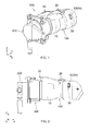
Fig. 1 is a perspective view showing a connector assembly comprising a connector and a mating connector according to an embodiment of the present invention. The connector and the mating connector are in a mated state. -
Fig. 2 is a side view showing the connector assembly ofFig. 1 . -
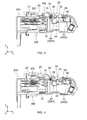
Fig. 3 is a cross-sectional view showing the connector assembly ofFig. 1 . The lock portion of the connector is positioned at a lock position. -
Fig. 4 is a cross-sectional view showing the connector assembly ofFig. 3 . The lock portion is positioned at an unlock position. -
Fig. 5 is a perspective view showing a mating connector ofFig. 1 . -
Fig. 6 is a perspective view showing a mating connector ofFig. 1 . -
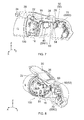
Fig. 7 is a partially cutaway cross-sectional, perspective view showing the connector ofFig. 6 . A lock maintenance member is under a permission state, and the lock portion is positioned at a lock position. -
Fig. 8 is a partially-cutaway, cross-sectional, perspective view showing the connector ofFig. 6 . A lock maintenance member is under the permission state, and the lock portion is positioned as the unlock position. -
Fig. 9 is a side view showing the connector ofFig. 8 . -
Fig. 10 is a rear view showing the connector ofFig. 8 . -
Fig. 11 is a partially-cutaway, cross-sectional, perspective view showing the connector ofFig. 6 . The lock member is positioned at the lock position, and the lock maintenance member is under a maintenance state. -
Fig. 12 is a side view showing the connector ofFig. 11 . -
Fig. 13 is a rear view showing the connector ofFig. 11 . -
Fig. 14 is a perspective view showing the lock member ofFig. 7 . -
Fig. 15 is a perspective view showing a first switch ofFig. 7 . -
Fig. 16 is a perspective view showing the lock maintenance member ofFig. 7 . -
Fig. 17 is a perspective view showing a second switch ofFig. 7 . -
Fig. 18 is a circuit diagram showing a comprehensive detection mechanism which comprises a position detection mechanism and a state detection mechanism of the connector according to the embodiment of the present invention. -
Fig. 19 is a graph showing a detection result of the comprehensive detection mechanism ofFig. 18 . -
Fig. 20 is a circuit diagram showing a modification of the comprehensive detection mechanism ofFig. 18 . -
Fig. 21 is a cross-sectional view showing the connector of Patent Document 1. - While the invention is susceptible to various modifications and alternative forms, specific embodiments thereof are shown by way of example in the drawings and will herein be described in detail. It should be understood, however, that the drawings and detailed description thereto are not intended to limit the invention to the particular form disclosed, but on the contrary, the intention is to cover all modifications, equivalents and alternatives falling within the spirit and scope of the present invention as defined by the appended claims.
- Referring to
Figs. 1 to 6 , aconnector assembly 300 according to an embodiment of the present invention comprises a connector (plug) 100 and a mating connector (inlet) 200 mateable with theconnector 100 in a Y-direction (front-rear direction). For example, themating connector 200 is a receiving connector provided on Electric Vehicle, while theconnector 100 is a charging connector or a power supply connector which is connected with a cable extending from an electric power supply system. Themating connector 200 may be a power supply connector provided on Electric Vehicle and theconnector 100 may be a receiving connector which receives electric power from Electric Vehicle. As shown inFigs. 3 to 5 , themating connector 200 is provided with a lockedportion 202. - As understood in
Figs. 3 to 13 , theconnector 100 according to the present embodiment comprises ahousing 10, abias member 15 formed of a coil spring, alock member 20 formed of a lock lever, aposition detection mechanism 40, and alock maintenance member 50 formed of a slider and astate detection mechanism 70. - As shown in
Fig. 14 , thelock member 20 has apivot 22, alock portion 24, afirst operation portion 26, a restrictedportion 28, anaccommodation portion 30 and apress portion 32. Thepivot 22 is positioned between thelock portion 24 and thefirst operation portion 26. The restrictedportion 28 is formed on an one end of thelock member 20. Theaccommodation portion 30 and thepress portion 32 are positioned between thepivot 22 and thefirst operation portion 26. In the present embodiment, thepress portion 32 is positioned between theaccommodation portion 30 and the restrictedportion 28. - As apparent from
Fig. 14 , thelock member 20 according to the present embodiment is formed of a single member. Specifically, thelock portion 24 and thefirst operation portion 26 are formed on the common member. Accordingly, thelock portion 24 is directly operated by operating thefirst operation portion 26. - As shown in
Figs. 3, 4 ,7, 8 and11 , thelock member 20 is supported by thehousing 10. Thepivot 22 extends toward an X-direction. Thelock portion 24 and thefirst operation portion 26 are movable in a seesaw manner with thepivot 22 as a center. In other word, thelock portion 24 is moved toward a positive Z-side (upper side) when thefirst operation portion 26 is moved toward a negative Z-side (lower side), while thelock portion 24 is moved toward the negative Z-side when thefirst operation portion 26 is moved toward the positive Z-side. Thefirst operation portion 26, the restrictedportion 28 and thepress portion 32 are provided in the vicinity of the one end of thelock member 20. More specifically, thefirst operation portion 26 is positioned at the positive Z-side above the restrictedportion 28 and thepress portion 32, the restrictedportion 28 and thepress portion 32 are positioned at the negative Z-side below thefirst operation portion 26. - The
accommodation portion 30 of thelock member 20 accommodates the bias member (coil spring) 15. An one end of thebias member 15 is fixed to thehousing 10, while the other end of thebias member 15 is abutted to an inside of theaccommodation portion 30. Thus, theaccommodation portion 30 continues to receive a spring force directed toward a positive Z-direction (upward). Accordingly, when thefirst operation portion 26 is not operated, thelock portion 24 is positioned at a position shown inFigs. 3 ,7 and11 . The position of thelock member 20 shown inFigs. 3 ,7 and11 is referred to as "lock position". When thefirst operation portion 26 is operated to be pressed in a negative Z-direction (first operation direction: downward), thelock portion 24 is moved in the positive Z-direction as shown inFigs. 4 and8 . A position of thelock member 20 shown inFigs. 4 and8 is referred to as "unlock position". - Thus, the
lock member 20 is selectively positionable at the lock position or the unlock position. Thelock member 20 of the present invention is urged to be moved to the lock position by thebias member 15. When thefirst operation portion 26 is operated in the first operation direction (negative Z-direction), thelock member 20 is moved from the lock position to the unlock position. When the operation of thefirst operation portion 26 is stopped, thelock member 20 returns to the lock position again by thebias member 15. - As understood from
Fig. 3 , when thelock member 20 is positioned at the lock position, thelock portion 24 locks the lockedportion 202 of themating connector 200 to lock a mating of theconnector 100 with themating connector 200. As understood fromFig. 4 , when thelock member 20 is positioned at the unlock position, the lock of thelock portion 24 with the lockedportion 202 of themating connector 200 is released. Therefore, when thelock member 20 is positioned at the unlock position, theconnector 100 is removable from themating connector 200. - As understood in
Figs. 3 and 4 , theposition detection mechanism 40 is to detect whether thelock member 20 is positioned at the lock position or the unlock position. - As understood in
Fig. 18 , theposition detection mechanism 40 according to the present embodiment has a first parallel circuit PC1 which is constituted by connecting a first switch SW1 and a first resistor Ra in parallel. A resistance value of the first resistor Ra according to the present embodiment is 220 Ω. The first resistor Ra may have another resistance value. In addition, instead of the first resistor Ra, another impedance element may be used. - The first parallel circuit PC1 has a first variable impedance which has an impedance variable in response to a switching condition of the first switch SW1. More specifically, an impedance of the first variable impedance is 0 Ω when the first switch SW1 is closed while being 220 Ω when the first switch SW1 is opened.
- As shown in
Fig. 15 , the first switch SW1 according to the present embodiment is formed of a limit switch in which an end of anarm 42 is pressed so that abutton 44 is pressed. The first switch SW1 is a normally closed type switch. In other word, the first switch SW1 is closed under a normal state, while the first switch SW1 is opened when thebutton 44 is pressed through thearm 42. - As shown in
Figs. 3, 4 ,7 and11 , the first switch SW1 is installed within thehousing 10. The first switch SW1 is positioned at the negative Z-side (downward) of thelock member 20. In particular, as shown inFigs. 3 and 4 , the end of thearm 42 is positioned at the negative Z-side (downward) of thepress portion 32 of thelock member 20. As understood fromFig. 3 , when thelock member 20 is positioned at the lock position, thearm 42 is not brought into contact with thepress portion 32. Thus, the first switch SW1 is closed. As understood fromFig. 4 , when thelock member 20 is positioned at the unlock position, thearm 42 is pressed by thepress portion 32 so that thebutton 44 is pressed. Thus, the first switch SW1 is opened. As understood from the above, the switching condition of the first switch SW1 is changed over in accordance with whether thelock member 20 is positioned at the lock position or the unlock position. In addition, if the first switch SW1 is closed (i.e. if thebutton 44 is not pressed) when thelock member 20 is positioned at the lock position, thearm 42 and thepress portion 32 may be brought into contact with each other. In order to control a switching condition of the first switch SW1 as intended in consideration of unevenness on production quality and unevenness on assembly, it is preferable that thearm 42 and thepress portion 32 are not brought into contact with each other when thelock member 20 is positioned at the lock position. - As shown in
Fig. 16 , thelock maintenance member 50 according to the present embodiment has amain portion 52 and astopper 60 projecting out in a direction perpendicular to themain portion 52. Themain portion 52 is provided with a receivingportion 58 recessed in a projecting direction of thestopper 60. Both ends of themain portion 52 serve as asecond operation portion 54 and athird operation portion 56, respectively. Thesecond operation portion 54 and thethird operation portion 56 have end portions extending toward an oblique direction, respectively. As described later, shapes of thesecond operation portion 54 and thethird operation portion 56 match with an outer shape of thehousing 10. If thehousing 10 has a shape different from the outer shape, thesecond operation portion 54 and thethird operation portion 56 may have shapes other than the shapes. - As shown in
Figs. 7, 8 and11 , thelock maintenance member 50 is held by thehousing 10. Themain portion 52 extends along the X-direction (lateral direction) so that thelock maintenance member 50 is slidable along the X-direction. Themain portion 52 is positioned at a positive Y-side (rear side) of thelock member 20. Thestopper 60 projects in a negative Y-direction (forward: third direction) from themain portion 52. - The
lock maintenance member 50 is selectively takable one of two states: a state where thesecond operation portion 54 greatly projects out from the housing 10 (seeFigs. 6 and10 ); and a state where thethird operation portion 56 greatly projects out from the housing 10 (seeFig. 13 ). The former state of thelock maintenance member 50 is referred to as "maintenance state". The latter state of thelock maintenance member 50 is referred to as "permission state". Specifically, when thesecond operation portion 54 is pressed along a negative X-direction (second operation direction), thethird operation portion 56 greatly projects out from thehousing 10 so that thelock maintenance member 50 transits a state thereof from the permission state to the maintenance state. When thethird operation portion 56 is pressed along a positive X-direction (direction opposite to the second operation direction), thesecond operation portion 54 greatly projects out from thehousing 10 so that thelock maintenance member 50 transits a state thereof from the maintenance state to the permission state. - As shown in
Figs. 7 and11 , because there is an empty space in the negative Z-side (down side) of the restrictedportion 28 when thelock member 20 is positioned at the lock position, thelock maintenance member 50 does not abut against thestopper 60 even if thelock maintenance member 50 slides toward the X-direction so that thestopper 60 is moved in the X-direction. In other word, when thelock member 20 is positioned at the lock position, thelock maintenance member 50 is selectively takable the maintenance state or the permission state. - As shown in
Fig. 11 , when thelock maintenance member 50 is under the maintenance state, thestopper 60 is positioned at the negative Z-side of the restrictedportion 28 of thelock member 20. Therefore, even if thelock member 20 is urged to be moved to the unlock position by operating thefirst operation portion 26 of thelock member 20, the restrictedportion 28 abuts against thestopper 60 so that thelock member 20 is unable to be moved to the unlock position. In other word, when thelock maintenance member 50 is under the maintenance state, thestopper 60 restricts a movement of the restrictedportion 28 of thelock member 20 so that thelock member 20 is restricted to be moved from the lock position to the unlock position and that the mating of theconnector 100 with themating connector 200 is locked. - As understood in
Figs. 7 and 8 , when thelock maintenance member 50 is under the permission state, thestopper 60 is not positioned at the negative Z-side of the restrictedportion 28 of thelock member 20. Therefore, thestopper 60 does not restrict a movement of thelock member 20 so that thelock member 20 is freely positionable between the lock position and the unlock position. In other word, when thelock maintenance member 50 is under the permission state, thelock member 20 is freely movable between the lock position and the unlock position. - As shown in
Figs. 8 , when thelock member 20 is positioned at the unlock position, thestopper 60 is positioned at the positive X-side of thelock member 20. Therefore, even if thelock maintenance member 50 is urged to slide toward the negative X-direction, thestopper 60 abuts against thelock member 20 so that thelock maintenance member 50 is unable to be moved. In other word, when thelock member 20 is under the unlock position, thelock maintenance member 50 is unable to transit a state thereof to the permission state. - As understood in
Figs. 7, 8 and11 , thestate detection mechanism 70 is combined with thelock maintenance member 50. Thestate detection mechanism 70 is to detect whether thelock maintenance member 50 is under the maintenance state or the permission state. - As understood in
Fig. 18 , thestate detection mechanism 70 according to the present embodiment has a second parallel circuit PC2 which is constituted by connecting a second switch SW2 and a second resistor Rb in parallel. A resistance value of the second resistor Rb according to the present embodiment is 330 Ω. The second resistor Rb may have another resistance value. Instead of the second resistor Rb, another impedance element may be used. However, in a circuit structure according to the present embodiment, in order to be able to distinguish between a detection result of thestate detection mechanism 70 and a detection result of theposition detection mechanism 40, it is necessary that the second resistor Rb has a resistance value which is different from a resistance value of the first resistor Ra. - The second parallel circuit PC2 has a second variable impedance which has an impedance variable in accordance with a switching condition of the second switch SW2. More specifically, an impedance of the second variable impedance is 0 Ω when the second switch SW2 is closed while being is 330 Ω when the second switch SW2 is opened.
- As shown in
Fig. 17 , the second switch SW2 according to the present embodiment is a slide switch. The switching condition of the second switch SW2 is changed over by sliding atab 72. - As shown in
Figs. 3, 4 ,7, 8 and11 , the second switch SW2 is installed within thehousing 10 and is positioned at the positive Y-side (rear side) of thelock maintenance member 50. In particular, thetab 72 of the second switch SW2 is engaged in the receivingportion 58 of thelock maintenance member 50. The second switch SW2 can be turned on/off by sliding operation of thelock maintenance member 50. More specifically, when thelock maintenance member 50 is under the maintenance state, i.e., when thethird operation portion 56 greatly projects out from thehousing 10, the second switch SW2 is closed. When thelock maintenance member 50 is under the permission state, i.e., when thesecond operation portion 54 greatly projects out from thehousing 10, the second switch SW2 is opened. - As shown in
Fig. 18 , in the present embodiment, theposition detection mechanism 40 and thestate detection mechanism 70 are connected with each other to form a singlecomprehensive detection mechanism 80 which has asingle output portion 82. More specifically, thecomprehensive detection mechanism 80 according to the present embodiment has a circuit which is formed by connecting the first parallel circuit PC1, the second parallel circuit PC2 and a third resistor Rc in series. Accordingly, thecomprehensive detection mechanism 80 has a combined variable impedance in which the first variable impedance, the second variable impedance and resistance value (impedance) of the third resistor Rc are combined. - As shown in
Fig. 19 , the combined variable impedance has four kinds of impedances according to combinations of the detection result of theposition detection mechanism 40 and the detection result of thestate detection mechanism 70. This change of impedance is reflected on a signal outputted from theoutput portion 82 of thecomprehensive detection mechanism 80. Specifically, the signal output from theoutput portion 82 includes the detection result of theposition detection mechanism 40 and the detection result of thestate detection mechanism 70, which are superposed with each other. - More specifically, when the first switch SW1 is closed while the second switch SW2 is closed, the
lock member 20 is positioned at the lock position while thelock maintenance member 50 is under the maintenance state (combination C1). Therefore, when theconnector 100 is mated with themating connector 200, electric power can be transmitted and received. When the first switch SW1 is opened while the second switch SW2 is closed, thelock member 20 is positioned at the unlock position while thelock maintenance member 50 is under the maintenance state (combination C2). The combination C2 cannot occur under a state where each component of theconnector 100 is properly moved. Specifically, there is a high possibility that the combination C2 occurs under a state where the components are improperly engaged with each other. When the first switch SW1 is closed while the second switch SW2 is opened, thelock member 20 is positioned at the lock position while thelock maintenance member 50 is under the permission state (combination C3). Specifically, thelock maintenance member 50 is, either intentionally or unintentionally, under the permission state. For example, the combination C3 may indicate that thelock maintenance member 50 is misunderstood to take the maintenance state and that thestopper 60 is unable to restrict the movement of the restrictedportion 28 by an imperfect operation of thesecond operation portion 54. In this case, thefirst operation portion 26 is freely operable so that there is a high possibility that theconnector 100 is come off from themating connector 200 by easily releasing the lock. When the first switch SW1 is opened while the second switch SW2 is opened, thelock member 20 is positioned at the unlock position while thelock maintenance member 50 is under the permission state (combination C4). Specifically, the combination C4 indicates that thefirst operation portion 26 of thelock member 20 is intended to be operated to unlock the lock. Thus, in the present embodiment, a position of thelock member 20 and a state of thelock maintenance member 50 can be grasped in detail. - In a system (e.g., power supply system) employing the
connector 100 according to the present embodiment, four kinds of the detection results can be displayed according to combinations of the detection results of theposition detection mechanism 40 and the detection result of thestate detection mechanism 70. - In the
connector 100 according to the present embodiment, thelock maintenance member 50 which restricts the movement of thelock member 20 is manually operated. Thus, as compared with a connector comprising a solenoid, theconnector 100 can be formed at low cost and miniaturized, and a state of thelock maintenance member 50 can be surely switched. - In addition, by provision of two detection mechanisms, i.e. the
position detection mechanism 40 and thestate detection mechanism 70, it can be identified whether a situation where electric power is unable to be supplied is caused by thelock portion 24 not locking the lockedportion 202 or by thelock maintenance member 50 not maintaining the lock. - While the present invention has been described with specific embodiments, the present invention is not limited to the aforementioned embodiments. The present invention is variously modifiable and applicable.
- For example, the
aforementioned lock member 20 is exposed to an outside of thehousing 10. Most of thelock member 20 may be accommodated into thehousing 10 if thefirst operation portion 26 is operable from the outside of thehousing 10. - Although the aforementioned first switch SW1 is normally closed type switch, the first switch SW1 may be normally open type switch. Although the first switch SW1 is a limit switch, the first switch SW1 may be another type of switch. Although the second switch SW2 is a slide switch, the second switch SW2 may be another type of switch.
- Furthermore, although the
position detection mechanism 40 and thestate detection mechanism 70 are formed of the first parallel circuit PC1 and the second parallel circuit PC2, respectively in above-described embodiment, theposition detection mechanism 40 may be formed of a series circuit and thestate detection mechanism 70 may be formed of a series circuit. - For example, as shown in
Fig. 20 , theposition detection mechanism 40 may have a first series circuit SC1 which is formed by connecting the first switch SW1 and the first resistor Ra in series, and thestate detection mechanism 70 may have a second series circuit SC2 which is formed by connecting the second switch SW2 and the second resistor Rb in series. Furthermore, the first series circuit SC1, the second series circuit SC2 and the third resistor Rc may be connected in parallel to form thecomprehensive detection mechanism 80. Also in that case, theoutput portion 82 can output a signal output which includes the detection result of theposition detection mechanism 40 and the detection result of thestate detection mechanism 70, which are superposed with each other. - The present application is based on a Japanese patent application of
JP2013-216790 - While there has been described what is believed to be the preferred embodiment of the invention, those skilled in the art will recognize that other and further modifications may be made thereto without departing from the spirit of the invention, and it is intended to claim all such embodiments that fall within the true scope of the invention.
Claims (10)
- A connector mateable with a mating connector having a locked portion, the connector comprising:a lock member, wherein: the lock member has a lock portion; the lock member is selectively positionable at a lock position or an unlock position; when the lock member is positioned at the lock position, the lock portion locks the locked portion to lock a mating of the connector with the mating connector; and, when the lock member is positioned at the unlock position, the connector is removable from the mating connector;a position detection mechanism which detects whether the lock member is positioned at the lock position or the unlock position;a lock maintenance member selectively takable a maintenance state or a permission state, wherein: when the lock maintenance member is under the maintenance state, the lock maintenance member restricts a movement of the lock member from the lock position to the unlock position to maintain a lock of the mating; and, when the lock maintenance member is under the permission state, the lock maintenance member permits the lock member to move from the lock position to the unlock position; anda state detection mechanism which detects whether the lock maintenance member is under the maintenance state or the permission state.
- The connector as recited in claim 1, wherein:the lock member has a first operation portion;when the first operation portion is operated toward a first operation direction, the lock member is moved from the lock position to the unlock position;the lock maintenance member has a second operation portion; andwhen the second operation portion is operated toward a second operation direction intersecting the first operation direction, the lock maintenance member transits a state thereof from the maintenance state to the permission state.
- The connector as recited in claim 2, wherein:the connector further comprises a housing; andthe lock maintenance member is a slider held by the housing so as to be movable along the second operation direction.
- The connector as recited in claim3, wherein:the lock member further comprises a pivot and a restricted portion;the pivot is positioned between the lock portion and the first operation portion;the lock member is supported by the housing so that the lock portion and the first operation portion are movable in a seesaw manner with the pivot as a center;the lock maintenance member is provided with a stopper projecting in a third direction intersecting both the first operation direction and the second operation direction; andwhen the lock maintenance member is under the permission state, the stopper does not restrict the restricted portion to move along the first operation direction; and, when the lock maintenance member is under the maintenance state, the stopper restricts the restricted portion to move along the first operation direction.
- The connector as recited in claim 2, wherein the lock member is formed of a single member having the lock portion and the first operation portion.
- The connector as recited in claim 1, further comprising a bias member which urges the lock member to move toward the lock position.
- The connector as recited in claim 1, wherein:the position detection mechanism and the state detection mechanism are connected with each other to form a single comprehensive detection mechanism which has a single output portion; anda signal output from the output portion of the comprehensive detection mechanism includes a detection result of the position detection mechanism and a detection result of the state detection mechanism, which are superposed with each other.
- the connector as recited in claim 7, wherein:the position detection mechanism comprises a first switch and a first variable impedance;a switching condition of the first switch is changed over in accordance with whether the lock member is positioned at the lock position or the unlock position;an impedance of the first variable impedance is changed over in accordance with the switching condition of the first switch;the state detection mechanism comprises a second switch and a second variable impedance;a switching condition of the second switch is changed over in accordance with whether the lock maintenance member is under the maintenance state or the permission state;an impedance of the second variable impedance is changed over in accordance with the switching condition of the second switch;the comprehensive detection mechanism comprises a combined variable impedance which has the first variable impedance and the second variable impedance; andthe combined variable impedance has four kinds of impedances according to combinations of the detection result of the position detection mechanism and the detection result of the state detection mechanism.
- The connector as recited in claim 8, wherein:the position detection mechanism further comprises a first resistor;the first resistor and the first switch are connected in parallel to form a first parallel circuit;the state detection mechanism further comprises a second resistor having a resistance value which is different from a resistance value of the first resistor;the second resistor and the second switch are connected in parallel to form a second parallel circuit; andthe comprehensive detection mechanism has a circuit in which the first parallel circuit and the second parallel circuit are connected in series.
- A system comprising the connector as recited in claim 1, wherein four kinds of the detection results are displayed according to combinations of the detection result of the position detection mechanism and the detection result of the state detection mechanism.
Applications Claiming Priority (1)
| Application Number | Priority Date | Filing Date | Title |
|---|---|---|---|
| JP2013216790A JP6148964B2 (en) | 2013-10-17 | 2013-10-17 | connector |
Publications (2)
| Publication Number | Publication Date |
|---|---|
| EP2863488A1 true EP2863488A1 (en) | 2015-04-22 |
| EP2863488B1 EP2863488B1 (en) | 2017-02-01 |
Family
ID=51355490
Family Applications (1)
| Application Number | Title | Priority Date | Filing Date |
|---|---|---|---|
| EP14181391.5A Not-in-force EP2863488B1 (en) | 2013-10-17 | 2014-08-19 | Connector |
Country Status (4)
| Country | Link |
|---|---|
| US (1) | US9225109B2 (en) |
| EP (1) | EP2863488B1 (en) |
| JP (1) | JP6148964B2 (en) |
| CN (2) | CN107069323B (en) |
Cited By (5)
| Publication number | Priority date | Publication date | Assignee | Title |
|---|---|---|---|---|
| EP3139452A1 (en) * | 2015-09-02 | 2017-03-08 | Japan Aviation Electronics Industry, Ltd. | Connector and connector assembly |
| WO2020212114A1 (en) * | 2019-04-18 | 2020-10-22 | Leoni Bordnetz-Systeme Gmbh | Apparatus, plug connector set, indicator element and method for identifying initial disconnection of a plug connection |
| US20220118869A1 (en) * | 2020-10-21 | 2022-04-21 | Rivian Ip Holdings, Llc | Holster sensor for electric vehicle charging system |
| WO2022089682A1 (en) * | 2020-10-30 | 2022-05-05 | Kiekert Ag | Locking device driven by an electric motor |
| CN116345234A (en) * | 2021-12-22 | 2023-06-27 | 日本航空电子工业株式会社 | charging connector |
Families Citing this family (21)
| Publication number | Priority date | Publication date | Assignee | Title |
|---|---|---|---|---|
| JP5981294B2 (en) * | 2012-10-12 | 2016-08-31 | 矢崎総業株式会社 | Charging inlet device |
| WO2014157196A1 (en) * | 2013-03-28 | 2014-10-02 | 矢崎総業株式会社 | Charging connector |
| JP6148964B2 (en) * | 2013-10-17 | 2017-06-14 | 日本航空電子工業株式会社 | connector |
| TWM519340U (en) * | 2015-06-17 | 2016-03-21 | 宣德科技股份有限公司 | Electronic connector combination |
| JP6452568B2 (en) * | 2015-07-24 | 2019-01-16 | 日本航空電子工業株式会社 | Electrical connector |
| CN106114272A (en) * | 2016-08-18 | 2016-11-16 | 深圳市华鸿贤精密技术有限公司 | A kind of integrated electronic lock and the charging gun of signal feedback |
| CN106329225B (en) * | 2016-11-16 | 2019-07-30 | 奥动新能源汽车科技有限公司 | Male plug and connection device for electric vehicle battery module |
| JP2018110472A (en) * | 2016-12-28 | 2018-07-12 | 三菱電機株式会社 | Charging / discharging system, power conditioner and cable |
| CN106848716A (en) * | 2017-03-30 | 2017-06-13 | 天津市弘昌蒲公英电子科技发展有限公司 | Fool proof charging socket |
| CA3073492A1 (en) * | 2017-08-21 | 2019-02-28 | Hubbell Incorporated | Electrical contact device with interlock |
| CN107666078A (en) * | 2017-10-30 | 2018-02-06 | 蔚来汽车有限公司 | Charging gun locking system, vehicle body assembly and charging gun |
| USD924156S1 (en) * | 2017-11-17 | 2021-07-06 | Curbell Medical Products, Inc. | Electrical connector |
| DE102018109530A1 (en) * | 2018-04-20 | 2019-10-24 | Harting Electric Gmbh & Co. Kg | Device and method for load-free disconnection of a connector |
| DE102018131610A1 (en) * | 2018-12-10 | 2020-06-10 | Phoenix Contact E-Mobility Gmbh | Charging plug with a detent connection detection |
| EP3745541B1 (en) * | 2019-05-31 | 2022-09-14 | ERICH JAEGER GmbH + Co. KG | Socket for a combined electrical connection and data connection |
| JP7481942B2 (en) * | 2020-08-06 | 2024-05-13 | 日本航空電子工業株式会社 | Charging connector |
| EP3979433A1 (en) * | 2020-10-01 | 2022-04-06 | TE Connectivity Germany GmbH | Housing assembly with a spring biased cpa |
| DE102021103075A1 (en) | 2021-02-10 | 2022-08-11 | Kiekert Aktiengesellschaft | ELECTRIC MOTOR-DRIVEN LOCKING DEVICE |
| CN114006223B (en) * | 2021-10-28 | 2024-05-14 | 深圳市泰格莱精密电子有限公司 | Charging connector and electric automobile |
| KR102698311B1 (en) * | 2022-11-30 | 2024-08-26 | 현대모비스 주식회사 | Charging gun disconnecting apparatus |
| DE102023200501A1 (en) * | 2023-01-24 | 2024-07-25 | Vitesco Technologies GmbH | Safety device for high-voltage connections of an electrically powered vehicle |
Citations (10)
| Publication number | Priority date | Publication date | Assignee | Title |
|---|---|---|---|---|
| US20080150718A1 (en) * | 2006-12-21 | 2008-06-26 | Silicon Laboratories, Inc. | Powered device including a detection signature circuit |
| WO2008142490A1 (en) * | 2007-05-24 | 2008-11-27 | Fci | A mating detection device, a connector and a connector assembly therewith |
| US8025526B1 (en) * | 2010-04-21 | 2011-09-27 | Coulomb Technologies, Inc. | Self powered electric vehicle charging connector locking system |
| JP2012130127A (en) * | 2010-12-14 | 2012-07-05 | Takaoka Electric Mfg Co Ltd | Charging device for electric moving body |
| US20120232761A1 (en) * | 2011-03-08 | 2012-09-13 | GM Global Technology Operations LLC | Passive charge cord release system for an electric vehicle |
| US20120234061A1 (en) * | 2011-03-18 | 2012-09-20 | Kabushiki Kaisha Tokai Rika Denki Seisakusho | Power plug locking device |
| JP2013008466A (en) | 2011-06-22 | 2013-01-10 | Daiden Co Ltd | Connector for power feeding |
| US20130078840A1 (en) * | 2011-09-28 | 2013-03-28 | Kabushiki Kaisha Tokai Rika Denki Seisakusho | Power plug locking device |
| WO2013108338A1 (en) * | 2012-01-17 | 2013-07-25 | Yazaki Corporation | Electrical connector |
| US20130250506A1 (en) * | 2012-03-23 | 2013-09-26 | Sony Corporation | Electronic apparatus |
Family Cites Families (30)
| Publication number | Priority date | Publication date | Assignee | Title |
|---|---|---|---|---|
| US5627448A (en) * | 1993-04-22 | 1997-05-06 | Sumitomo Wiring Systems, Ltd. | Electric vehicle charging connector assembly |
| US5458496A (en) * | 1993-07-12 | 1995-10-17 | Sumitomo Wiring Systems, Ltd. | Charge coupling for electric vehicle |
| DE19544942C2 (en) * | 1994-12-01 | 2001-12-06 | Yazaki Corp | Connecting device with a voltage supply connector and a voltage receiving connector and method for connecting / disconnecting a voltage supply device |
| JP3292278B2 (en) * | 1995-12-06 | 2002-06-17 | 矢崎総業株式会社 | Electric vehicle charging connector |
| JP3731797B2 (en) * | 1999-11-08 | 2006-01-05 | 矢崎総業株式会社 | Power supply connector |
| US9113880B2 (en) * | 2007-10-05 | 2015-08-25 | Covidien Lp | Internal backbone structural chassis for a surgical device |
| JP3832836B2 (en) * | 2003-10-31 | 2006-10-11 | 日本航空電子工業株式会社 | Optical connector adapter |
| US7296937B1 (en) * | 2006-05-05 | 2007-11-20 | Tyco Electronics Corporation | Transceiver module assembly with unlatch detection switch |
| JP4766619B2 (en) * | 2008-07-22 | 2011-09-07 | 日本航空電子工業株式会社 | Optical adapter |
| JP5341477B2 (en) * | 2008-11-04 | 2013-11-13 | 矢崎総業株式会社 | connector |
| US7963793B2 (en) * | 2009-09-24 | 2011-06-21 | Lear Corporation | Hybrid/electric vehicle charge handle latch mechanism |
| JP4801765B2 (en) * | 2009-09-30 | 2011-10-26 | 日本航空電子工業株式会社 | Optical connector and optical connector cable |
| JP5231381B2 (en) * | 2009-11-17 | 2013-07-10 | 株式会社東海理化電機製作所 | Connector lock structure for battery charging power receiving connector |
| JP4925229B2 (en) * | 2009-11-30 | 2012-04-25 | 日本航空電子工業株式会社 | connector |
| JP5096518B2 (en) * | 2010-05-12 | 2012-12-12 | 株式会社東海理化電機製作所 | Power supply plug lock device |
| US8075329B1 (en) * | 2010-06-08 | 2011-12-13 | Ford Global Technologies, Llc | Method and system for preventing disengagement between an electrical plug and a charge port on an electric vehicle |
| JP5890091B2 (en) * | 2010-10-29 | 2016-03-22 | 日本航空電子工業株式会社 | Electric connector, electric connector unit, and charger for electric vehicle |
| JP5192029B2 (en) * | 2010-11-25 | 2013-05-08 | 日本航空電子工業株式会社 | Connector and connector unit |
| US8568155B2 (en) * | 2010-12-30 | 2013-10-29 | General Cable Technologies Corporation | Laminous multi-polymeric high amperage over-molded connector assembly for plug-in hybrid electric vehicle charging |
| DE102011000094B4 (en) * | 2011-01-11 | 2021-09-02 | Huf Hülsbeck & Fürst Gmbh & Co. Kg | System for access control to a vehicle charging device |
| JP5080662B2 (en) | 2011-01-27 | 2012-11-21 | 日本航空電子工業株式会社 | connector |
| JP5635437B2 (en) * | 2011-03-18 | 2014-12-03 | 株式会社東海理化電機製作所 | Power supply plug lock device |
| JP5826594B2 (en) * | 2011-10-28 | 2015-12-02 | 日本航空電子工業株式会社 | connector |
| JP5798935B2 (en) * | 2012-01-17 | 2015-10-21 | 矢崎総業株式会社 | Electrical connector |
| JP5916476B2 (en) * | 2012-03-29 | 2016-05-11 | 古河電気工業株式会社 | Power supply connector |
| JP5956826B2 (en) * | 2012-05-10 | 2016-07-27 | 日本航空電子工業株式会社 | connector |
| CN202917768U (en) * | 2012-10-30 | 2013-05-01 | 安费诺-泰姆斯(常州)通讯设备有限公司 | Charging seat for electromobile |
| JP5947202B2 (en) * | 2012-12-13 | 2016-07-06 | 株式会社東海理化電機製作所 | Locking device |
| JP6148964B2 (en) * | 2013-10-17 | 2017-06-14 | 日本航空電子工業株式会社 | connector |
| US8968021B1 (en) * | 2013-12-11 | 2015-03-03 | JAE Oregon, Inc. | Self-rejecting automotive harness connector |
-
2013
- 2013-10-17 JP JP2013216790A patent/JP6148964B2/en not_active Expired - Fee Related
-
2014
- 2014-08-19 EP EP14181391.5A patent/EP2863488B1/en not_active Not-in-force
- 2014-08-25 US US14/467,386 patent/US9225109B2/en not_active Expired - Fee Related
- 2014-08-29 CN CN201610821452.5A patent/CN107069323B/en not_active Expired - Fee Related
- 2014-08-29 CN CN201410437423.XA patent/CN104577509B/en not_active Expired - Fee Related
Patent Citations (10)
| Publication number | Priority date | Publication date | Assignee | Title |
|---|---|---|---|---|
| US20080150718A1 (en) * | 2006-12-21 | 2008-06-26 | Silicon Laboratories, Inc. | Powered device including a detection signature circuit |
| WO2008142490A1 (en) * | 2007-05-24 | 2008-11-27 | Fci | A mating detection device, a connector and a connector assembly therewith |
| US8025526B1 (en) * | 2010-04-21 | 2011-09-27 | Coulomb Technologies, Inc. | Self powered electric vehicle charging connector locking system |
| JP2012130127A (en) * | 2010-12-14 | 2012-07-05 | Takaoka Electric Mfg Co Ltd | Charging device for electric moving body |
| US20120232761A1 (en) * | 2011-03-08 | 2012-09-13 | GM Global Technology Operations LLC | Passive charge cord release system for an electric vehicle |
| US20120234061A1 (en) * | 2011-03-18 | 2012-09-20 | Kabushiki Kaisha Tokai Rika Denki Seisakusho | Power plug locking device |
| JP2013008466A (en) | 2011-06-22 | 2013-01-10 | Daiden Co Ltd | Connector for power feeding |
| US20130078840A1 (en) * | 2011-09-28 | 2013-03-28 | Kabushiki Kaisha Tokai Rika Denki Seisakusho | Power plug locking device |
| WO2013108338A1 (en) * | 2012-01-17 | 2013-07-25 | Yazaki Corporation | Electrical connector |
| US20130250506A1 (en) * | 2012-03-23 | 2013-09-26 | Sony Corporation | Electronic apparatus |
Cited By (11)
| Publication number | Priority date | Publication date | Assignee | Title |
|---|---|---|---|---|
| EP3139452A1 (en) * | 2015-09-02 | 2017-03-08 | Japan Aviation Electronics Industry, Ltd. | Connector and connector assembly |
| US9711904B2 (en) | 2015-09-02 | 2017-07-18 | Japan Aviation Electronics Industry, Limited | Connector and connector assembly |
| WO2020212114A1 (en) * | 2019-04-18 | 2020-10-22 | Leoni Bordnetz-Systeme Gmbh | Apparatus, plug connector set, indicator element and method for identifying initial disconnection of a plug connection |
| US20220118869A1 (en) * | 2020-10-21 | 2022-04-21 | Rivian Ip Holdings, Llc | Holster sensor for electric vehicle charging system |
| US11518258B2 (en) * | 2020-10-21 | 2022-12-06 | Rivian Ip Holdings, Llc | Holster sensor for electric vehicle charging system |
| WO2022089682A1 (en) * | 2020-10-30 | 2022-05-05 | Kiekert Ag | Locking device driven by an electric motor |
| US12515545B2 (en) | 2020-10-30 | 2026-01-06 | Kiekert Ag | Locking device driven by an electric motor |
| CN116345234A (en) * | 2021-12-22 | 2023-06-27 | 日本航空电子工业株式会社 | charging connector |
| EP4203200A1 (en) * | 2021-12-22 | 2023-06-28 | Japan Aviation Electronics Industry, Limited | Charging connector |
| US12573793B2 (en) | 2021-12-22 | 2026-03-10 | Japan Aviation Electronics Industry, Limited | Charging connector |
| CN116345234B (en) * | 2021-12-22 | 2026-04-10 | 日本航空电子工业株式会社 | Charging connector |
Also Published As
| Publication number | Publication date |
|---|---|
| CN104577509A (en) | 2015-04-29 |
| US9225109B2 (en) | 2015-12-29 |
| JP2015079679A (en) | 2015-04-23 |
| US20150111408A1 (en) | 2015-04-23 |
| CN107069323A (en) | 2017-08-18 |
| CN107069323B (en) | 2019-04-16 |
| CN104577509B (en) | 2017-04-12 |
| EP2863488B1 (en) | 2017-02-01 |
| JP6148964B2 (en) | 2017-06-14 |
Similar Documents
| Publication | Publication Date | Title |
|---|---|---|
| US9225109B2 (en) | Connector | |
| EP3139452B1 (en) | Connector and connector assembly | |
| US9812820B2 (en) | Electrical connector and returning jig | |
| EP2988375B1 (en) | Connector device | |
| JP5916476B2 (en) | Power supply connector | |
| US5435748A (en) | Connector with fitting detection function | |
| JP5890091B2 (en) | Electric connector, electric connector unit, and charger for electric vehicle | |
| JP6099203B2 (en) | Connector device | |
| US20170133790A1 (en) | Lever-Type Connector Assembly | |
| US9088096B2 (en) | Power feed connector | |
| JP5798935B2 (en) | Electrical connector | |
| CN109428194B (en) | Charging plug-in connector with operating means | |
| US20120064751A1 (en) | Electrical Connector Assembly | |
| CN113659392A (en) | A secondary locking mechanism and a secondary locking connector | |
| EP3392898B1 (en) | Magnetic trip device of air circuit breaker | |
| KR20210100531A (en) | Connector Locking Mechanism | |
| CN100536251C (en) | Connector and method for controlling the assembly thereof | |
| GB2441878A (en) | Connector with locking lever | |
| JP2014127318A (en) | Fitting structure of connector | |
| JP2013149386A (en) | Electric connector | |
| US7950949B2 (en) | Connector and electronic device system | |
| JP5970596B2 (en) | Electric connector, electric connector unit, and charger for electric vehicle | |
| JP2014107200A (en) | Power supply connector | |
| JP5845368B2 (en) | Electric connector, electric connector unit, and charger for electric vehicle |
Legal Events
| Date | Code | Title | Description |
|---|---|---|---|
| PUAI | Public reference made under article 153(3) epc to a published international application that has entered the european phase |
Free format text: ORIGINAL CODE: 0009012 |
|
| 17P | Request for examination filed |
Effective date: 20140819 |
|
| AK | Designated contracting states |
Kind code of ref document: A1 Designated state(s): AL AT BE BG CH CY CZ DE DK EE ES FI FR GB GR HR HU IE IS IT LI LT LU LV MC MK MT NL NO PL PT RO RS SE SI SK SM TR |
|
| AX | Request for extension of the european patent |
Extension state: BA ME |
|
| R17P | Request for examination filed (corrected) |
Effective date: 20150918 |
|
| RBV | Designated contracting states (corrected) |
Designated state(s): AL AT BE BG CH CY CZ DE DK EE ES FI FR GB GR HR HU IE IS IT LI LT LU LV MC MK MT NL NO PL PT RO RS SE SI SK SM TR |
|
| 17Q | First examination report despatched |
Effective date: 20160201 |
|
| GRAP | Despatch of communication of intention to grant a patent |
Free format text: ORIGINAL CODE: EPIDOSNIGR1 |
|
| RIC1 | Information provided on ipc code assigned before grant |
Ipc: H01R 13/639 20060101ALI20160801BHEP Ipc: H01R 13/641 20060101ALI20160801BHEP Ipc: H01R 13/627 20060101AFI20160801BHEP Ipc: B60L 11/18 20060101ALI20160801BHEP Ipc: H01R 13/66 20060101ALI20160801BHEP |
|
| INTG | Intention to grant announced |
Effective date: 20160818 |
|
| GRAS | Grant fee paid |
Free format text: ORIGINAL CODE: EPIDOSNIGR3 |
|
| GRAA | (expected) grant |
Free format text: ORIGINAL CODE: 0009210 |
|
| AK | Designated contracting states |
Kind code of ref document: B1 Designated state(s): AL AT BE BG CH CY CZ DE DK EE ES FI FR GB GR HR HU IE IS IT LI LT LU LV MC MK MT NL NO PL PT RO RS SE SI SK SM TR |
|
| REG | Reference to a national code |
Ref country code: GB Ref legal event code: FG4D |
|
| REG | Reference to a national code |
Ref country code: CH Ref legal event code: EP Ref country code: AT Ref legal event code: REF Ref document number: 866261 Country of ref document: AT Kind code of ref document: T Effective date: 20170215 |
|
| REG | Reference to a national code |
Ref country code: IE Ref legal event code: FG4D |
|
| REG | Reference to a national code |
Ref country code: DE Ref legal event code: R096 Ref document number: 602014006498 Country of ref document: DE |
|
| REG | Reference to a national code |
Ref country code: NL Ref legal event code: MP Effective date: 20170201 |
|
| REG | Reference to a national code |
Ref country code: LT Ref legal event code: MG4D |
|
| REG | Reference to a national code |
Ref country code: AT Ref legal event code: MK05 Ref document number: 866261 Country of ref document: AT Kind code of ref document: T Effective date: 20170201 |
|
| PG25 | Lapsed in a contracting state [announced via postgrant information from national office to epo] |
Ref country code: HR Free format text: LAPSE BECAUSE OF FAILURE TO SUBMIT A TRANSLATION OF THE DESCRIPTION OR TO PAY THE FEE WITHIN THE PRESCRIBED TIME-LIMIT Effective date: 20170201 Ref country code: NO Free format text: LAPSE BECAUSE OF FAILURE TO SUBMIT A TRANSLATION OF THE DESCRIPTION OR TO PAY THE FEE WITHIN THE PRESCRIBED TIME-LIMIT Effective date: 20170501 Ref country code: GR Free format text: LAPSE BECAUSE OF FAILURE TO SUBMIT A TRANSLATION OF THE DESCRIPTION OR TO PAY THE FEE WITHIN THE PRESCRIBED TIME-LIMIT Effective date: 20170502 Ref country code: LT Free format text: LAPSE BECAUSE OF FAILURE TO SUBMIT A TRANSLATION OF THE DESCRIPTION OR TO PAY THE FEE WITHIN THE PRESCRIBED TIME-LIMIT Effective date: 20170201 Ref country code: IS Free format text: LAPSE BECAUSE OF FAILURE TO SUBMIT A TRANSLATION OF THE DESCRIPTION OR TO PAY THE FEE WITHIN THE PRESCRIBED TIME-LIMIT Effective date: 20170601 Ref country code: FI Free format text: LAPSE BECAUSE OF FAILURE TO SUBMIT A TRANSLATION OF THE DESCRIPTION OR TO PAY THE FEE WITHIN THE PRESCRIBED TIME-LIMIT Effective date: 20170201 |
|
| PG25 | Lapsed in a contracting state [announced via postgrant information from national office to epo] |
Ref country code: AT Free format text: LAPSE BECAUSE OF FAILURE TO SUBMIT A TRANSLATION OF THE DESCRIPTION OR TO PAY THE FEE WITHIN THE PRESCRIBED TIME-LIMIT Effective date: 20170201 Ref country code: NL Free format text: LAPSE BECAUSE OF FAILURE TO SUBMIT A TRANSLATION OF THE DESCRIPTION OR TO PAY THE FEE WITHIN THE PRESCRIBED TIME-LIMIT Effective date: 20170201 Ref country code: PL Free format text: LAPSE BECAUSE OF FAILURE TO SUBMIT A TRANSLATION OF THE DESCRIPTION OR TO PAY THE FEE WITHIN THE PRESCRIBED TIME-LIMIT Effective date: 20170201 Ref country code: ES Free format text: LAPSE BECAUSE OF FAILURE TO SUBMIT A TRANSLATION OF THE DESCRIPTION OR TO PAY THE FEE WITHIN THE PRESCRIBED TIME-LIMIT Effective date: 20170201 Ref country code: LV Free format text: LAPSE BECAUSE OF FAILURE TO SUBMIT A TRANSLATION OF THE DESCRIPTION OR TO PAY THE FEE WITHIN THE PRESCRIBED TIME-LIMIT Effective date: 20170201 Ref country code: SE Free format text: LAPSE BECAUSE OF FAILURE TO SUBMIT A TRANSLATION OF THE DESCRIPTION OR TO PAY THE FEE WITHIN THE PRESCRIBED TIME-LIMIT Effective date: 20170201 Ref country code: RS Free format text: LAPSE BECAUSE OF FAILURE TO SUBMIT A TRANSLATION OF THE DESCRIPTION OR TO PAY THE FEE WITHIN THE PRESCRIBED TIME-LIMIT Effective date: 20170201 Ref country code: PT Free format text: LAPSE BECAUSE OF FAILURE TO SUBMIT A TRANSLATION OF THE DESCRIPTION OR TO PAY THE FEE WITHIN THE PRESCRIBED TIME-LIMIT Effective date: 20170601 Ref country code: BG Free format text: LAPSE BECAUSE OF FAILURE TO SUBMIT A TRANSLATION OF THE DESCRIPTION OR TO PAY THE FEE WITHIN THE PRESCRIBED TIME-LIMIT Effective date: 20170501 |
|
| PG25 | Lapsed in a contracting state [announced via postgrant information from national office to epo] |
Ref country code: RO Free format text: LAPSE BECAUSE OF FAILURE TO SUBMIT A TRANSLATION OF THE DESCRIPTION OR TO PAY THE FEE WITHIN THE PRESCRIBED TIME-LIMIT Effective date: 20170201 Ref country code: IT Free format text: LAPSE BECAUSE OF FAILURE TO SUBMIT A TRANSLATION OF THE DESCRIPTION OR TO PAY THE FEE WITHIN THE PRESCRIBED TIME-LIMIT Effective date: 20170201 Ref country code: SK Free format text: LAPSE BECAUSE OF FAILURE TO SUBMIT A TRANSLATION OF THE DESCRIPTION OR TO PAY THE FEE WITHIN THE PRESCRIBED TIME-LIMIT Effective date: 20170201 Ref country code: CZ Free format text: LAPSE BECAUSE OF FAILURE TO SUBMIT A TRANSLATION OF THE DESCRIPTION OR TO PAY THE FEE WITHIN THE PRESCRIBED TIME-LIMIT Effective date: 20170201 Ref country code: EE Free format text: LAPSE BECAUSE OF FAILURE TO SUBMIT A TRANSLATION OF THE DESCRIPTION OR TO PAY THE FEE WITHIN THE PRESCRIBED TIME-LIMIT Effective date: 20170201 |
|
| REG | Reference to a national code |
Ref country code: DE Ref legal event code: R097 Ref document number: 602014006498 Country of ref document: DE |
|
| PG25 | Lapsed in a contracting state [announced via postgrant information from national office to epo] |
Ref country code: SM Free format text: LAPSE BECAUSE OF FAILURE TO SUBMIT A TRANSLATION OF THE DESCRIPTION OR TO PAY THE FEE WITHIN THE PRESCRIBED TIME-LIMIT Effective date: 20170201 Ref country code: DK Free format text: LAPSE BECAUSE OF FAILURE TO SUBMIT A TRANSLATION OF THE DESCRIPTION OR TO PAY THE FEE WITHIN THE PRESCRIBED TIME-LIMIT Effective date: 20170201 |
|
| PLBE | No opposition filed within time limit |
Free format text: ORIGINAL CODE: 0009261 |
|
| STAA | Information on the status of an ep patent application or granted ep patent |
Free format text: STATUS: NO OPPOSITION FILED WITHIN TIME LIMIT |
|
| 26N | No opposition filed |
Effective date: 20171103 |
|
| PG25 | Lapsed in a contracting state [announced via postgrant information from national office to epo] |
Ref country code: SI Free format text: LAPSE BECAUSE OF FAILURE TO SUBMIT A TRANSLATION OF THE DESCRIPTION OR TO PAY THE FEE WITHIN THE PRESCRIBED TIME-LIMIT Effective date: 20170201 |
|
| REG | Reference to a national code |
Ref country code: CH Ref legal event code: PL |
|
| PG25 | Lapsed in a contracting state [announced via postgrant information from national office to epo] |
Ref country code: MC Free format text: LAPSE BECAUSE OF FAILURE TO SUBMIT A TRANSLATION OF THE DESCRIPTION OR TO PAY THE FEE WITHIN THE PRESCRIBED TIME-LIMIT Effective date: 20170201 |
|
| PG25 | Lapsed in a contracting state [announced via postgrant information from national office to epo] |
Ref country code: CH Free format text: LAPSE BECAUSE OF NON-PAYMENT OF DUE FEES Effective date: 20170831 Ref country code: LI Free format text: LAPSE BECAUSE OF NON-PAYMENT OF DUE FEES Effective date: 20170831 |
|
| REG | Reference to a national code |
Ref country code: FR Ref legal event code: ST Effective date: 20180430 |
|
| REG | Reference to a national code |
Ref country code: IE Ref legal event code: MM4A |
|
| REG | Reference to a national code |
Ref country code: BE Ref legal event code: MM Effective date: 20170831 |
|
| PG25 | Lapsed in a contracting state [announced via postgrant information from national office to epo] |
Ref country code: LU Free format text: LAPSE BECAUSE OF NON-PAYMENT OF DUE FEES Effective date: 20170819 |
|
| PG25 | Lapsed in a contracting state [announced via postgrant information from national office to epo] |
Ref country code: IE Free format text: LAPSE BECAUSE OF NON-PAYMENT OF DUE FEES Effective date: 20170819 |
|
| PG25 | Lapsed in a contracting state [announced via postgrant information from national office to epo] |
Ref country code: BE Free format text: LAPSE BECAUSE OF NON-PAYMENT OF DUE FEES Effective date: 20170831 Ref country code: FR Free format text: LAPSE BECAUSE OF NON-PAYMENT OF DUE FEES Effective date: 20170831 |
|
| PG25 | Lapsed in a contracting state [announced via postgrant information from national office to epo] |
Ref country code: MT Free format text: LAPSE BECAUSE OF NON-PAYMENT OF DUE FEES Effective date: 20170819 |
|
| GBPC | Gb: european patent ceased through non-payment of renewal fee |
Effective date: 20180819 |
|
| PG25 | Lapsed in a contracting state [announced via postgrant information from national office to epo] |
Ref country code: HU Free format text: LAPSE BECAUSE OF FAILURE TO SUBMIT A TRANSLATION OF THE DESCRIPTION OR TO PAY THE FEE WITHIN THE PRESCRIBED TIME-LIMIT; INVALID AB INITIO Effective date: 20140819 |
|
| PG25 | Lapsed in a contracting state [announced via postgrant information from national office to epo] |
Ref country code: CY Free format text: LAPSE BECAUSE OF FAILURE TO SUBMIT A TRANSLATION OF THE DESCRIPTION OR TO PAY THE FEE WITHIN THE PRESCRIBED TIME-LIMIT Effective date: 20170201 Ref country code: GB Free format text: LAPSE BECAUSE OF NON-PAYMENT OF DUE FEES Effective date: 20180819 |
|
| PG25 | Lapsed in a contracting state [announced via postgrant information from national office to epo] |
Ref country code: MK Free format text: LAPSE BECAUSE OF FAILURE TO SUBMIT A TRANSLATION OF THE DESCRIPTION OR TO PAY THE FEE WITHIN THE PRESCRIBED TIME-LIMIT Effective date: 20170201 |
|
| PG25 | Lapsed in a contracting state [announced via postgrant information from national office to epo] |
Ref country code: TR Free format text: LAPSE BECAUSE OF FAILURE TO SUBMIT A TRANSLATION OF THE DESCRIPTION OR TO PAY THE FEE WITHIN THE PRESCRIBED TIME-LIMIT Effective date: 20170201 |
|
| PG25 | Lapsed in a contracting state [announced via postgrant information from national office to epo] |
Ref country code: AL Free format text: LAPSE BECAUSE OF FAILURE TO SUBMIT A TRANSLATION OF THE DESCRIPTION OR TO PAY THE FEE WITHIN THE PRESCRIBED TIME-LIMIT Effective date: 20170201 |
|
| PGFP | Annual fee paid to national office [announced via postgrant information from national office to epo] |
Ref country code: DE Payment date: 20210706 Year of fee payment: 8 |
|
| REG | Reference to a national code |
Ref country code: DE Ref legal event code: R119 Ref document number: 602014006498 Country of ref document: DE |
|
| PG25 | Lapsed in a contracting state [announced via postgrant information from national office to epo] |
Ref country code: DE Free format text: LAPSE BECAUSE OF NON-PAYMENT OF DUE FEES Effective date: 20230301 |