EP2863484A1 - Drahtorganisator - Google Patents
Drahtorganisator Download PDFInfo
- Publication number
- EP2863484A1 EP2863484A1 EP20140188813 EP14188813A EP2863484A1 EP 2863484 A1 EP2863484 A1 EP 2863484A1 EP 20140188813 EP20140188813 EP 20140188813 EP 14188813 A EP14188813 A EP 14188813A EP 2863484 A1 EP2863484 A1 EP 2863484A1
- Authority
- EP
- European Patent Office
- Prior art keywords
- organizer
- lead
- clamping
- opening
- electrical line
- Prior art date
- Legal status (The legal status is an assumption and is not a legal conclusion. Google has not performed a legal analysis and makes no representation as to the accuracy of the status listed.)
- Granted
Links
Images


Classifications
-
- H—ELECTRICITY
- H01—ELECTRIC ELEMENTS
- H01R—ELECTRICALLY-CONDUCTIVE CONNECTIONS; STRUCTURAL ASSOCIATIONS OF A PLURALITY OF MUTUALLY-INSULATED ELECTRICAL CONNECTING ELEMENTS; COUPLING DEVICES; CURRENT COLLECTORS
- H01R13/00—Details of coupling devices of the kinds covered by groups H01R12/70 or H01R24/00 - H01R33/00
- H01R13/58—Means for relieving strain on wire connection, e.g. cord grip, for avoiding loosening of connections between wires and terminals within a coupling device terminating a cable
- H01R13/5804—Means for relieving strain on wire connection, e.g. cord grip, for avoiding loosening of connections between wires and terminals within a coupling device terminating a cable comprising a separate cable clamping part
- H01R13/5812—Means for relieving strain on wire connection, e.g. cord grip, for avoiding loosening of connections between wires and terminals within a coupling device terminating a cable comprising a separate cable clamping part the cable clamping being achieved by mounting the separate part on the housing of the coupling device
-
- H—ELECTRICITY
- H01—ELECTRIC ELEMENTS
- H01R—ELECTRICALLY-CONDUCTIVE CONNECTIONS; STRUCTURAL ASSOCIATIONS OF A PLURALITY OF MUTUALLY-INSULATED ELECTRICAL CONNECTING ELEMENTS; COUPLING DEVICES; CURRENT COLLECTORS
- H01R11/00—Individual connecting elements providing two or more spaced connecting locations for conductive members which are, or may be, thereby interconnected, e.g. end pieces for wires or cables supported by the wire or cable and having means for facilitating electrical connection to some other wire, terminal, or conductive member, blocks of binding posts
- H01R11/01—Individual connecting elements providing two or more spaced connecting locations for conductive members which are, or may be, thereby interconnected, e.g. end pieces for wires or cables supported by the wire or cable and having means for facilitating electrical connection to some other wire, terminal, or conductive member, blocks of binding posts characterised by the form or arrangement of the conductive interconnection between the connecting locations
-
- H—ELECTRICITY
- H01—ELECTRIC ELEMENTS
- H01R—ELECTRICALLY-CONDUCTIVE CONNECTIONS; STRUCTURAL ASSOCIATIONS OF A PLURALITY OF MUTUALLY-INSULATED ELECTRICAL CONNECTING ELEMENTS; COUPLING DEVICES; CURRENT COLLECTORS
- H01R11/00—Individual connecting elements providing two or more spaced connecting locations for conductive members which are, or may be, thereby interconnected, e.g. end pieces for wires or cables supported by the wire or cable and having means for facilitating electrical connection to some other wire, terminal, or conductive member, blocks of binding posts
- H01R11/03—Individual connecting elements providing two or more spaced connecting locations for conductive members which are, or may be, thereby interconnected, e.g. end pieces for wires or cables supported by the wire or cable and having means for facilitating electrical connection to some other wire, terminal, or conductive member, blocks of binding posts characterised by the relationship between the connecting locations
- H01R11/09—Individual connecting elements providing two or more spaced connecting locations for conductive members which are, or may be, thereby interconnected, e.g. end pieces for wires or cables supported by the wire or cable and having means for facilitating electrical connection to some other wire, terminal, or conductive member, blocks of binding posts characterised by the relationship between the connecting locations the connecting locations being identical
-
- H—ELECTRICITY
- H01—ELECTRIC ELEMENTS
- H01R—ELECTRICALLY-CONDUCTIVE CONNECTIONS; STRUCTURAL ASSOCIATIONS OF A PLURALITY OF MUTUALLY-INSULATED ELECTRICAL CONNECTING ELEMENTS; COUPLING DEVICES; CURRENT COLLECTORS
- H01R13/00—Details of coupling devices of the kinds covered by groups H01R12/70 or H01R24/00 - H01R33/00
- H01R13/46—Bases; Cases
- H01R13/52—Dustproof, splashproof, drip-proof, waterproof, or flameproof cases
- H01R13/5205—Sealing means between cable and housing, e.g. grommet
- H01R13/5208—Sealing means between cable and housing, e.g. grommet having at least two cable receiving openings
Definitions
- the present invention relates to an organizer body for holding at least one electrical line in a wire organizer, the organizer body comprising at least one lead-through opening extending from a back side to a front side of the organizer body in an insertion direction for leading the electrical line from the back side to the front side.
- the present invention relates to a clamping element for clamping at least one electrical line with an organizer body of a wire organizer.
- the present invention relates to a construction kit for a wire organizer, comprising at least one organizer body.
- the present invention relates to a wire organizer for holding at least one electrical line, comprising an organizer body.
- the present invention relates to a method for fastening at least one electrical line within a wire organizer, the method comprising the steps of introducing the at least one electrical line in an insertion direction into a through-hole of an organizer body of the wire organizer, such that the at least one electrical line enters the lead-through opening at a back side of the wire organizer and exits the lead-through opening at a front side of the wire organizer.
- wire organizers Organizer bodies of wire organizers, the wire organizers themselves, construction kits therefor and methods for fastening at least one electrical line within a wire organizer, as mentioned above, are known from the prior art.
- the wire organizers may e.g. be used for holding electrical lines with pigtail connections in order to connect the lines to printed circuit boards (PCB) or to simply attach the lines to a carrier or to electrically connect lines to each other.
- PCB printed circuit boards
- Known solutions therefor work e.g. with a direct contact unit for connecting the lines to the PCB.
- the line then has to be connected to a housing of the direct contact unit by a harness maker and the PCB will be assembled at a different manufacturing location.
- a wire organizer comprising such a housing has to fulfill several very strict requirements.
- a positioning tolerance of an end of the electrical line may be lesser than +/-0.2 mm in a longitudinal direction as well as a transverse direction of the wire organizer.
- a positioning tolerance in a height direction may be less than +/-0.3 mm.
- an problem underlying the present invention is to provide a wire organizer which allows for precise positioning of electrical lines and which is more cost-efficient as well as easy to handle.
- the at least one lead-through opening is at least partly laterally intersecting with a shaft adapted for receiving a clamping element.
- the above-mentioned problem is solved in that the clamping element is formed complementary to the at least one shaft of an organizer body according to the present invention.
- the construction kit comprises at least one organizer body according to the present invention and at least one clamping element according to the present invention.
- the wire organizer comprises an organizer body according to the present invention and at least one clamping element according to the present invention, wherein at least one electrical line enters the lead-through opening at the back side and exits the lead-through opening at the front side, and wherein the at least one clamping element is received within the shaft and fastens the at least one electrical line.
- the above-mentioned problem is solved according to the present invention in that the method further comprises the step of introducing in a clamping direction extending transversely to the insertion direction a clamping element into a shaft of the organizer body, such that the clamping element fastens the at least one electrical line within the lead-through opening at an intersection of the lead-through opening and the shaft.
- the solution allows the electrical line to be easily fastened within the organizer body in that the clamping element is introduced into the shaft when the electrical line is in the desired position.
- the electrical line especially an end section of the electrical line, may be precisely positioned in the longitudinal, transverse and height direction.
- the lead-through opening may intersect with the shaft in a plane extending in parallel to the insertion direction and the longitudinal direction of the clamping element. Both the lead-through opening and the shaft may be formed channel-like.
- the line may be clamped e.g. in a sheath of the line.
- the clamping may be achieved manually or automatically by hand or machine-operated tools, respectively.
- the parts of the wire organizer as well as the tools for its manufacturing and handling may have a simple design and thus be efficiently manufactured and handled, which helps in minimizing the costs involved for producing and handling the wire organizer.
- the shaft may open against a clamping direction extending transversely to the insertion direction.
- the clamping direction may extend essentially perpendicularly to the insertion direction.
- the clamping element may thereby be inserted in parallel to the clamping direction into the shaft.
- a transition between the shaft and the lead-through opening may thereby essentially extend in a direction extending transversely or essentially perpendicularly to the insertion direction as well as the clamping direction.
- a passage between the lead-through opening and the shaft may constitute an opening between the lead-through opening and the shaft extending essentially in a plane in parallel with the insertion direction and the clamping direction.
- the clamping element may thereby be easily pushed with its front end beyond the electrical line in the clamping direction, so that the clamping element clamps the electrical line within the lead-through opening by means of its side face.
- the wire organizer may comprise at least one further lead-through opening intersecting with the at least one shaft. Thereby, two electrical lines accommodated in the at least two lead-through openings may be fastened by introducing a single clamping element into the shaft.
- the at least one shaft may be arranged between the at least two lead-through openings. Thereby, two electrical lines, each received in a lead-through opening, may be fastened simultaneously when introducing the clamping element into the shaft.
- the at least one lead-through opening may intersect with the at least one shaft at at least two intersections distanced from each other along the insertion direction.
- the electrical line may be fastened at two fastening regions or points distanced from each other in the insertion direction.
- the electrical line can be securely fastened within the lead-through opening, so that movements of the electrical line in the insertion direction may be prevented and especially an end section of the electrical line may be precisely located in the insertion direction.
- the at least one shaft may be mirror-symmetrically shaped with respect to a plane extending in parallel to the insertion direction and the clamping direction.
- a clamping element which may also be mirror-symmetrically shaped with respect to said plane, may be introduced into the shafted in at least two and up to four different orientations which facilitates handling the organizer body and the clamping element.
- Malleable leading elements may extend essentially in parallel to the insertion direction within the at least one lead-through opening at least in the vicinity of the front side.
- the leading elements may be flexible, elastically and/or plastically deformable.
- the leading elements may be shaped rib- or tongue-like and may extend essentially in parallel to the insertion direction while protruding from an inner circumference of the lead-through opening into the lead-through opening.
- the leading elements may be arranged concentrically with respect to a middle axis of the at least one lead-through opening, extending in parallel to the insertion direction. Thereby, the electrical line may be easily centered within the lead-through opening.
- the solution according to the present invention may be further improved in that the clamping element and at least one further clamping element are connected to each other by at least one connecting part.
- the clamping element, the at least one further clamping element and the connecting part may be integrally formed.
- the connecting part may be formed as a material bridge between the at least one and the at least one further clamping element.
- the clamping element may comprise at least one clamping block from which at least one rib extending in parallel to the clamping direction protrudes.
- the clamping block may provide a desired stability to the clamping element while the at least one rib may help to notch the electrical line or a sheath thereof in order to precisely fasten the electrical line within the shaft.
- the solution may be further improved in that the construction kit further comprises at one of a housing providing a cavity for accommodating the at least one organizer body, a sealing element for sealing up between the housing and the organizer body, and a contact block adapted to accommodate contact elements for electrically connecting a tip of an electrical line held in the organizer body to a tip of another electrical line held in another organizer body.
- the construction kit may enable the organizer body to be protectively accommodated within the housing and the housing may be sealed.
- two organizer bodies and, if desired, their respective housing may each form a sort of plug element providing a plug-connector for electrically connecting the tips of electrical lines to each other.
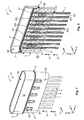
- Fig. 1 shows a first embodiment of a wire organizer 1 in a fully assembled state F.
- the wire organizer 1 extends in a longitudinal direction X, a transverse direction Y and a height direction Z, which together define a Cartesian coordinate system.
- the wire organizer 1 comprises an organizer body 2, a number of clamping elements 3, a number of electrical lines 4 and sealing elements 5. Electricals lines 4 are each held in one of a number of lead-through openings 20 (not yet shown) provided in the organizer body and extending from a back side 23 to a front side 24 (not yet shown) thereof.
- Shafts 21 formed in the organizer body 2 each intersect with the lead-through openings 20 at two intersections 22, where the clamping elements 3 fasten the electrical lines 4.
- the electrical lines 4 are inserted into the organizer body in an insertion direction I extending in parallel to the height direction Z.
- the clamping elements 3 are inserted into the organizer body 2 at a lateral side thereof in a clamping direction C extending in parallel to the transverse direction Y.
- the organizer body 2 is provided with a receptacle 26 opening in a plug direction S wherein the wire organizer 1 may be mated with another wire organizer or any connecting means in an electrical component, PCB or the like.
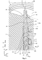
- Fig. 2 shows a schematic cross-sectional view of the wire organizer 1 in the fully assembled state F along a cross-sectional plane extending in parallel to the longitudinal direction X and the height direction Z through the lead-through openings 20 formed in the organizer body 2 as well as the electrical lines received therein.
- the lead-through openings 20 extend in parallel to the insertion direction I from the back side 23 to the front side 24, which forms a bottom of the receptacle 26.
- the electrical lines 4 are received in the lead-through openings 20 such that a stripped-off end section 40 of the electrical line 4 and hence a bare tip 41 thereof juts above the front side 24 of the organizer body 2 while a section of the electrical line 4 provided with an insulating sheath 42 is arranged within the respective lead-through opening 20 and extends beyond the back side 23 of the organizer body 2.
- Each of the shafts 21 is arranged between two of the lead-through openings 20. With the first of the two lead-through openings, the shaft intersects at two intersections 22a and 22b distanced from each other in the insertion direction I. With the second of the two lead-through openings 20, the shaft intersects at two intersections 22c and 22d also following each other in the insertion direction I. Further, it becomes apparent in Fig. 2 that along the inner circumference of the receptacle 26 another sealing element 5 is arranged near or abutting the front side 24.
- Fig. 3 is a schematic perspective cross-sectional view of a detail X depicted in Fig. 2 .
- the clamping element 3 comprises two clamping blocks 30a and 30b which are arranged in the intersections 22a and 22b respectively and are connected to each other via a bridge 31.
- a groove 32 is formed at each of the lateral sides of the clamping element 3 in order to receive the beam 27 and to provide guidance in the clamping direction C.
- Two ribs 33 are formed to each of the sides of each clamping block 30a, 30b so that they jut into the lead-through openings 20 at each of the intersections 22a to 22d and penetrate the electrical line 4 or at least the sheath 42 thereof in order to secure the electrical line 4 and inhibit any movements thereof in parallel to the insertion direction I.
- Clamping forces F C act in parallel to a fastening direction D from the clamping element 3 and in particular the ribs 33 thereof in and against the longitudinal direction X, i.e. perpendicularly to the insertion direction I and the clamping direction C.
- leading elements 20 are provided at the inner circumference of the lead-through opening 20 so that they center the end section 40 of the electrical line with respect to a middle axis M 20 of the lead-through opening 20.
- the lead-through opening 20 is extended in the insertion direction I by a rim 29 surrounding the lead-through opening 20 at the front side 24 and protruding therefrom.
- Fig. 4 is a schematic perspective cross-sectional view of the wire organizer 1 in the fully assembled state F along a middle axis M 3 of the clamping element 3 and a middle axis M 21 of one of the shafts 21, respectively, in a plane extending in parallel to the transverse direction Y and the height direction Z.
- the fastening directions D point away from each of the middles axes M 3 of the clamping element 3 and the middle axes M 21 of the shafts 21 essentially in parallel, i.e. in and against the longitudinal direction X, or in other terms perpendicularly to the insertion direction L as well as to the clamping direction C.
- the clamping element is provided with a cavity 34 in each clamping block 30a and 30b towards each of its front faces facing in and against the clamping direction C.
- the cavities 34 help to enhance a resiliency, i.e. flexibility or elastic deformability of the clamping element such that it may be compressed when being inserted into the respective shaft 21 in order to be snugly sitting therein while be held by force fit and/or positive fit in order to not accidentally be removed from the shaft 21.
- the shaft 21 extends from one of the lateral sides 25 of the organizer body 2 to the opposing lateral side 25 of the organizer body 2, i.e. through the entire organizer body 2.
- the clamping elements 3 within the shaft 21 may be accessed from both lateral sides 25 of the organizer body 2 in order to be able to remove the clamping element 3 from the shaft 21 by pushing it out of the shaft 21 from either of the lateral sides in the clamping direction C.
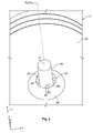
- Fig. 5 is a schematic perspective detailed view of the end section 40 of the electrical line 4 as it exits one of the lead-through openings 20.
- the leading elements 24 within the end region 20a of the lead-through opening 20 are arranged concentrically with respect to the middle axis M 20 of the lead-though opening 20.
- Each of the leading elements 28 is connected to the circular inner circumference of the lead-through opening 20 via a base 28a while a point 28b of the leading elements 28 is directed towards the middle axis M 20 of the lead-through opening 20 superimposed upon a middle axis M 4 of the electrical line 4.
- the point 28b enhances the malleability of the leading elements 28 and thereby facilitates centering the electrical line 4 or the stripped-off end section 40 thereof and thus the tip 41 in the lead-through opening 20.
- Figs. 6a-h each show the wire organizer 1 in a schematic perspective view from an unassembled state U in Fig. 6a over a first pre-assembled state P 1 ' in Fig. 6b to a fifth pre-assembled state P 5 in Fig. 6h .
- one of the electrical lines 4 is arranged below the organizer body 2 with its middle axis M 4 aligned with the middle axis M 20 of the first lead-through opening 20 in the row of the lead-through openings.
- the electrical line 4 is inserted into the lead-through opening 20 in a first step of a pre-assembled state P 1 '.
- a second electrical line 4 is inserted into the lead-through opening 20 next to the first lead-through opening 20 in a second step of a pre-assembled state P 1 ".
- one of the clamping elements 3 is arranged such that its middle axis M 3 is aligned with the middle axis M 21 of the shaft 21 connecting the lead-through openings 20 accommodating the two electrical lines 4 inserted therein.
- the clamping element 3 in a first pre-assembled state P 1 , the clamping element 3 is inserted into the shaft 21 between the two lead-through openings 20 accommodating the first two electrical lines 4. Thereby, a first pair of electrical lines 4 is simultaneously fastened within the respective pair of lead-through openings 20 intersecting with the shaft 21 arranged therebetween.
- a second step of a second pre-assembled state P 2 " another pair of electrical lines 4 is inserted into the pair of lead-through openings 20 arranged next to the first pair of lead-through openings 20 already equipped with electrical lines 4 which are fastened by means of the first clamping element 3.
- the second pair of electrical lines 4 is fastened within the second pair of lead-through openings 20 by means of a second clamping element 3, which, analogously to the first clamping element 3 sits between the first pair of electrical lines 4, is inserted into the shaft 21 arranged therebetween connecting the second pair of lead-through openings 20.
- a fifth pre-assembled state P 5 is shown, wherein all five pairs of lead-through openings of the wire organizer body 5 are equipped with electrical lines 4 such that the wire organizer body holds ten electrical lines 4. Between each of the five pairs of lead-through openings 20 holding a pair of electrical lines 4, a clamping element 3 is inserted into the respective shafts 21 connecting the respective lead-through openings 20 to each other.
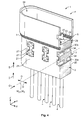
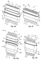
- Fig. 7 shows a schematic perspective view of a number of clamping elements 3 which are linked to each other so as to form as a clamping unit 300 which may be easily manually or automatically applied in a method for fastening at least one electrical line 4 within the wire organizer 1, e.g. as described with reference to Figs. 6a-h above.
- five clamping elements 3, which may be distanced from each other in the longitudinal direction X, at the same distance as the shafts 21 of the organizer body 2, are linked to each other via a first and a second connecting part 35a and 35b, respectively.
- Each of the connecting parts 35a and 35b comprises a bar 36 extending in parallel to the longitudinal direction X and link sections 37 extending from the bar 36 in and against the height direction Z, respectively, such that the link section 37 links the respective bar 36 to the clamping element 3.
- the link sections 37 taper from the bar 36 towards the clamping element 3 such that a cross-section of the link section 37 near the clamping element 3 is smaller than a cross-section of the link section 37 at the bar 36.
- the connecting parts 35a, 35b, in particular the bars are provided with studs 38 facilitating an alignment and handling of the clamping unit 300.
- An additional handling means 39 in the form of an eyelet formed at the connecting part 35a further facilitates handling and orientating the clamping unit 300.
- Figs. 8, 9 and 10 show the clamping unit 300 illustrated in Fig. 7 in a schematic front view, a cross-sectional view along the cross-sectional line A-A depicted in Fig. 8 , and a schematic top view, respectively.
- the clamping unit 300 is shaped mirror-symmetrically with respect to a plane extending in the middle of the connecting parts 35a and 35b i.e. in a plane extending in parallel to the longitudinal direction X and the height direction Z.
- the clamping unit 300 and the clamping elements 3 therein may be applied in the clamping direction C and a counter-clamping direction C', running opposite to the clamping direction C, which further facilitates applying the clamping unit 300 and the clamping elements 3 therein.
- Fig. 11 shows a schematic cross-sectional view of another embodiment of a wire organizer 1' according to the present invention in a cross-sectional plane extending through the middle axes M 20 of the lead-through openings 20' of the wire organizer 1' in a plane extending in parallel to the longitudinal direction X and the height direction Z.
- the wire organizer 1' comprises two organizer bodies 2', a number of clamping elements 3', is equipped with electrical lines 4', and further comprises sealing elements 5', a contact block 6', contact elements 7' and housings 8a, 8b.
- the electrical lines 4' are fastened within the lead-through openings 20' by means of the clamping elements 3' as described above with respect to the wire organizer 1.
- the opposing tips 41 of the stripped-off end sections 40 of the electrical lines 4 are electrically connected to each other by means of the contact elements 7 which are accommodated in a contact receptacle 60 of the contact blocks 6 extending essentially in parallel to the insertion direction I and thereby in parallel to the plug direction S as well as a counter plug direction S' running opposite to the plug direction S.
- the clamping block 6' is sandwiched between the two organizer bodies 2'.
- the arrangement of the two organizer bodies 2' and the contact block 6' therebetween is protectively held within the housings 8a, 8b and sealed-up against the environment by the sealing elements 5', each arranged between the respective organizer body and the housing 8a, 8b, thereby forming a so-called family seal.
- the electrical lines 4 enter the housings 8a, 8b through respective passages 80 formed therein, which are aligned to the lead-through openings 20' of the organizer bodies 2'.
- Figs. 12a-h show the wire organizer 1' in schematic perspective views illustrating the steps of pre-assembling and combining the parts of the wire organizer 1' until it has reached a fully assembled state F and a fully mated position K.
- Fig. 12a shows the organizer body 2' fully equipped with electrical lines 4 and clamping elements 3 in the fully assembled state F.
- the organizing body 2' is provided with a sealing element 5'.
- the contact block 6 is positioned with respect to one of the contact elements 7 such that the contact element 7 may be inserted into one of the ten contact receptacles 60 of the contact block 6 in or against the insertion direction I and the counter insertion direction I'.
- Fig. 12d a cross-sectional view of the contact block 6 along the middle axis M 60 of the contact receptacles 60 and the middle axis M 7 of the contact elements 7 is illustrated.
- Each of the ten contact receptacles 60 is equipped with a contact element.
- a third combined state Q 3 ' illustrated in Fig. 12e the contact block 6 fully equipped with contact elements 7 is arranged above the housing 8b accommodating the organizer body 2' such that the contact block 6 may be inserted into a receptacle 86b of the housing opening against the plug direction S.
- the contact block 6 is fully inserted into the receptacle 86b of the housing 8b.
- the wire organizer 2', the housing 8b and the contact block 6 thereby form a female plug element 100b ready to be mated with a plug element 100a in the counter-plug direction S'.
- FIG. 12g shows the plug element 100a and the counter-plug element 100b in a pre-mated position J where they are ready to be mated by being plugged together in the plug direction S or counter-plug direction S', respectively.
- the housing 8a is provided with a receptacle 86a, which is designed to receive a plug portion 81 of the housing 8b, i.e. the plug element 100b.
- Fig. 12h shows the plug element 100a and the counter-plug element 100b in the fully mated position K, i.e. the wire organizer 1' in a fifth or final combined state Q 5 with both its organizer bodies 2' in the fully assembled states F.
- the family sealing element 5' seals up between the receptacle 86a of the plug element 100a and the plug portion 81 of the counter-plug element 100b, while the further sealing elements 5' between the back sides of the organizer bodies 2' and the bottoms of the respective receptacles 86a and 86b provide that a connecting region of the electrical lines 4 within the contact block 6 is protected against moisture or other harmful environmental influences such as corrosive liquids or gases.
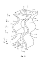
- Fig. 13 shows a schematic perspective view of a contact element 7 according to an embodiment of the present invention.
- the contact element may be formed as a single metal piece of e.g. stamped and bent sheet metal.
- the contact element 7 has an interior 70 which is surrounded by two wall portions 71 at lateral sides of the contact element 7 and is surrounded by two bottoms 72 facing in and against the plug direction S, respectively.
- a plug opening 33 is formed in each of the bottoms 72. Through the plug openings 33, the end sections 40 of two electrical lines 4 may be inserted in the plug direction S and the counter-plug direction S', respectively, such that the end sections 40 are received in the interior 70.
- the wall portions 71 are provided with sinusoidal bends 74 and are mirror-symmetrically shaped with respect to the middle axis M 7 of the contact element 7 in such a way that two contact regions 75 distanced from each other along the plug direction S are formed.
- the end section 40 may be accommodated within these contact regions 75 so that peaks 76 of the bends 74 opposing each other with respect to the middle axis M 7 electrically contact the respective end section 40 arranged between the opposing peaks 76 such that the contact element 7 electrically overrides a distance between the tips 41 of opposing electrical lines 4 in the plug direction S.
- the contact element 7 thereby serves as a sort of bridge or jumper in order to electrically connect the end sections 40 of opposing electrical lines 4 to each other.
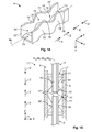
- Fig. 14 shows a schematic perspective view of another embodiment of a contact element 7' according to the present invention.
- the contact element 7' is shaped as a U-profile with bends 74' formed in its opposing sidewalls. Analogously to the contact element 7', these bends provide two contact regions 75' distanced from each other in the plug direction S. In the plug direction S and the counter-plug direction S', the contact regions 75' with peaks 76' are accessible through plug openings 73' at the ends of the contact element 7'.
- Fig. 15 shows the contact element 7' received in one of the contact receptacles 60 of the contact block 6.
- the tips 41 of the electrical lines 4 are opposing each other.
- the end section 40 of an electrical line 4 is electrically contacted by the peaks 76' opposing each other.
- Contact forces between the bends 74' and the end section 40 are supported via the wall portions 71' at opposing inner walls 61 of the contact receptacle 60.
- the contact element 7' is mirror-symmetrically shaped with respect to its middle axis M 7' .
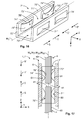
- Fig. 16 shows another embodiment of a contact element 7" according to the present invention in a schematic perspective view.
- the contact element 7" is shaped as a U-profile with bends 74" formed as tongue-like contact springs in opposing wall portions 71" of the contact element 7".
- the opposing bends 74" define contact regions 75" with peaks 76" between each other.
- Fig. 17 shows the contact element 7" received in a contact receptacle 60 of the contact block 6 in a schematic cross-sectional view along the middle axis M 7" of the contact element 7".
- the peaks 76" of the bends 74" electrically contact the stripped-off end sections 40 of the two electrical lines 4, the tips 41 of which oppose each other.
- contact forces acting between the peaks 76" and the electrical line 4 perpendicularly to the plug direction S, i.e. in and against the longitudinal direction X are supported via the side walls 71" or the contact element 7" at the inner walls 61 of the contact receptacle 60.
- the wire organizer 1,1' may comprise organizer bodies 2, 2', clamping elements 3, electrical lines 4, contact blocks 6, contact elements 7 and housings 8a, 8b in any number and form desired in order to be able to organize and attach electrical lines 4 within an electronic component, on a PCB or in order to form plug elements 100a, 100b.
- the organizer body 2, 2' may have lead-through openings 20, 20', shafts 21, intersections 22, 22a-22d, back sides 23, front sides 24, lateral sides 25, receptacles 26, beams 27, leading elements 28, bases 28a, points 28b, and rims 29 in any number and form desired according to a certain application.
- the clamping element 3 may comprise clamping blocks 30a, 30b, bridges 31, grooves 32, ribs 33, cavities 34, connecting parts 35a, 35b, bars 36, link sections 37, studs 38, and handling means 39, which may combined in clamping units 300 in any number and form desired for a certain application.
- the electrical lines 4 may have end sections 40, tips 41 and sheaths 42 in any number and form desired for a certain application. Stripped end sections 40 may be tinned and/or compacted wires or preassembled wires with final wire sleeves.
- the sealing elements 5, 5' may be formed and arranged as desired in order to seal-up a wire organizer 1, 1' as required for a certain application.
- the contact block 6 may have contact receptacles 60 with inner walls 61 in any number and form desired for receiving contact elements 7 according to the requirements of a certain application.
- the contact elements 7, 7', 7" may have an interior 70, 70', 70", wall portions 71, 71', 71", bottoms 72, 72', 72", plug openings 73, 73', 73", bends 74, 74', 74", contact regions 75, 75, 75" and peaks 76, 76', 76" in order to electrically contact an end section 40 or tip 41 of an electrical line 4 at as many contact points as desired for a certain application.
- the electrical line 4, i.e. its end section 40 and/or tip 41 may at one side of the contact element 7, 7', 7" e.g. at one of the contact regions 75, 75', 75" be connected to the contact element 7, 7', 7" by welding, soldering, crimping, etc. in a firmly bonded, force-fitted, frictionally engaged and/or positive-fit manner. Further features for absorbing shock and vibration may be added to the contact element 7, 7', 7" which may be produced from stamped sheet material or any other desired manufacturing technique or material.
- the housings 8a, 8b may be provided with passages 80, plug portions 81, receptacles 86a and 86b in any number and form required by a certain application.
Landscapes
- Details Of Connecting Devices For Male And Female Coupling (AREA)
- Insertion, Bundling And Securing Of Wires For Electric Apparatuses (AREA)
Applications Claiming Priority (1)
| Application Number | Priority Date | Filing Date | Title |
|---|---|---|---|
| IN4712CH2013 IN2013CH04712A (de) | 2013-10-18 | 2013-10-18 |
Publications (2)
| Publication Number | Publication Date |
|---|---|
| EP2863484A1 true EP2863484A1 (de) | 2015-04-22 |
| EP2863484B1 EP2863484B1 (de) | 2017-12-06 |
Family
ID=51862088
Family Applications (1)
| Application Number | Title | Priority Date | Filing Date |
|---|---|---|---|
| EP14188813.1A Active EP2863484B1 (de) | 2013-10-18 | 2014-10-14 | Drahtorganisator |
Country Status (2)
| Country | Link |
|---|---|
| EP (1) | EP2863484B1 (de) |
| IN (1) | IN2013CH04712A (de) |
Citations (2)
| Publication number | Priority date | Publication date | Assignee | Title |
|---|---|---|---|---|
| US4879810A (en) * | 1987-12-17 | 1989-11-14 | Amp Incorporated | Method for electrical wiring utilizing wire retainer |
| US20060189184A1 (en) * | 2005-02-24 | 2006-08-24 | Yazaki Corporation | Earthing plate and jig for mounting a coaxial cable thereon |
-
2013
- 2013-10-18 IN IN4712CH2013 patent/IN2013CH04712A/en unknown
-
2014
- 2014-10-14 EP EP14188813.1A patent/EP2863484B1/de active Active
Patent Citations (2)
| Publication number | Priority date | Publication date | Assignee | Title |
|---|---|---|---|---|
| US4879810A (en) * | 1987-12-17 | 1989-11-14 | Amp Incorporated | Method for electrical wiring utilizing wire retainer |
| US20060189184A1 (en) * | 2005-02-24 | 2006-08-24 | Yazaki Corporation | Earthing plate and jig for mounting a coaxial cable thereon |
Also Published As
| Publication number | Publication date |
|---|---|
| IN2013CH04712A (de) | 2015-04-24 |
| EP2863484B1 (de) | 2017-12-06 |
Similar Documents
| Publication | Publication Date | Title |
|---|---|---|
| US10256452B2 (en) | Cell contacting system for an electro-chemical device and method for producing a cell contacting system | |
| JP6454339B2 (ja) | 外部に設定される特定のバスシステムのソケット構造用の接触要素 | |
| KR20110063296A (ko) | 태양전지모듈용 단자박스 | |
| CN105322326B (zh) | 电端子 | |
| US10950962B2 (en) | Electrical connector and electrical cable arrangement connected thereto | |
| US9960518B2 (en) | Electrical cable connector and connector assembly thereof | |
| JP4100319B2 (ja) | 自動車用のスプライス吸収構造 | |
| CN110867705B (zh) | 电源连接器 | |
| EP2966774B1 (de) | Anschlusskasten | |
| US10622743B2 (en) | Terminal module with a conductive obliquely wound coil spring held against an electrical contact member and connector having such a terminal module | |
| JP2013027113A (ja) | 電線保持構造 | |
| US20150303624A1 (en) | Mezzanine receptacle connector | |
| EP3151345A1 (de) | Elektrischer steckverbinder | |
| KR20190001541A (ko) | 커넥터 스테이징 장치를 갖는 배선 하네스 | |
| JP2016058386A (ja) | レールマウントを備えた液没可能な電気コネクタ | |
| JP6550467B2 (ja) | 分岐コネクタ | |
| US12438302B2 (en) | Plug connector insert and method for the assembly thereof | |
| JP2021500713A (ja) | 偏平型電気コネクタ | |
| US7150661B2 (en) | Electrical and mechanical connecting device for an electrical connection unit | |
| EP1701415A2 (de) | Verbinder mit eingebauten Bauteilen und Leitungssatz | |
| EP2763255B1 (de) | Verbinder umfassend eine vielzahl von endkontakten und ein verbindergehäuse | |
| EP2863484B1 (de) | Drahtorganisator | |
| JP2014165048A (ja) | ジョイントバスバーおよびジョイントコネクタ | |
| EP1094569B1 (de) | Verbindungskontakt und Steckverbinder, welcher diesen Kontakt enthält | |
| EP0228723A2 (de) | Modularanschlussblock mit Isolationsverdrängungsklemmen |
Legal Events
| Date | Code | Title | Description |
|---|---|---|---|
| PUAI | Public reference made under article 153(3) epc to a published international application that has entered the european phase |
Free format text: ORIGINAL CODE: 0009012 |
|
| 17P | Request for examination filed |
Effective date: 20141014 |
|
| AK | Designated contracting states |
Kind code of ref document: A1 Designated state(s): AL AT BE BG CH CY CZ DE DK EE ES FI FR GB GR HR HU IE IS IT LI LT LU LV MC MK MT NL NO PL PT RO RS SE SI SK SM TR |
|
| AX | Request for extension of the european patent |
Extension state: BA ME |
|
| RAP1 | Party data changed (applicant data changed or rights of an application transferred) |
Owner name: TE CONNECTIVITY INDIA PRIVATE LIMITED Owner name: TE CONNECTIVITY GERMANY GMBH |
|
| R17P | Request for examination filed (corrected) |
Effective date: 20151022 |
|
| RBV | Designated contracting states (corrected) |
Designated state(s): AL AT BE BG CH CY CZ DE DK EE ES FI FR GB GR HR HU IE IS IT LI LT LU LV MC MK MT NL NO PL PT RO RS SE SI SK SM TR |
|
| 17Q | First examination report despatched |
Effective date: 20170202 |
|
| GRAP | Despatch of communication of intention to grant a patent |
Free format text: ORIGINAL CODE: EPIDOSNIGR1 |
|
| INTG | Intention to grant announced |
Effective date: 20170509 |
|
| GRAS | Grant fee paid |
Free format text: ORIGINAL CODE: EPIDOSNIGR3 |
|
| GRAA | (expected) grant |
Free format text: ORIGINAL CODE: 0009210 |
|
| AK | Designated contracting states |
Kind code of ref document: B1 Designated state(s): AL AT BE BG CH CY CZ DE DK EE ES FI FR GB GR HR HU IE IS IT LI LT LU LV MC MK MT NL NO PL PT RO RS SE SI SK SM TR |
|
| REG | Reference to a national code |
Ref country code: GB Ref legal event code: FG4D |
|
| REG | Reference to a national code |
Ref country code: AT Ref legal event code: REF Ref document number: 953179 Country of ref document: AT Kind code of ref document: T Effective date: 20171215 Ref country code: CH Ref legal event code: EP |
|
| REG | Reference to a national code |
Ref country code: IE Ref legal event code: FG4D |
|
| REG | Reference to a national code |
Ref country code: DE Ref legal event code: R096 Ref document number: 602014018125 Country of ref document: DE |
|
| REG | Reference to a national code |
Ref country code: SE Ref legal event code: TRGR |
|
| REG | Reference to a national code |
Ref country code: NL Ref legal event code: MP Effective date: 20171206 |
|
| REG | Reference to a national code |
Ref country code: LT Ref legal event code: MG4D |
|
| PG25 | Lapsed in a contracting state [announced via postgrant information from national office to epo] |
Ref country code: FI Free format text: LAPSE BECAUSE OF FAILURE TO SUBMIT A TRANSLATION OF THE DESCRIPTION OR TO PAY THE FEE WITHIN THE PRESCRIBED TIME-LIMIT Effective date: 20171206 Ref country code: ES Free format text: LAPSE BECAUSE OF FAILURE TO SUBMIT A TRANSLATION OF THE DESCRIPTION OR TO PAY THE FEE WITHIN THE PRESCRIBED TIME-LIMIT Effective date: 20171206 Ref country code: NO Free format text: LAPSE BECAUSE OF FAILURE TO SUBMIT A TRANSLATION OF THE DESCRIPTION OR TO PAY THE FEE WITHIN THE PRESCRIBED TIME-LIMIT Effective date: 20180306 Ref country code: LT Free format text: LAPSE BECAUSE OF FAILURE TO SUBMIT A TRANSLATION OF THE DESCRIPTION OR TO PAY THE FEE WITHIN THE PRESCRIBED TIME-LIMIT Effective date: 20171206 |
|
| REG | Reference to a national code |
Ref country code: AT Ref legal event code: MK05 Ref document number: 953179 Country of ref document: AT Kind code of ref document: T Effective date: 20171206 |
|
| PG25 | Lapsed in a contracting state [announced via postgrant information from national office to epo] |
Ref country code: RS Free format text: LAPSE BECAUSE OF FAILURE TO SUBMIT A TRANSLATION OF THE DESCRIPTION OR TO PAY THE FEE WITHIN THE PRESCRIBED TIME-LIMIT Effective date: 20171206 Ref country code: LV Free format text: LAPSE BECAUSE OF FAILURE TO SUBMIT A TRANSLATION OF THE DESCRIPTION OR TO PAY THE FEE WITHIN THE PRESCRIBED TIME-LIMIT Effective date: 20171206 Ref country code: HR Free format text: LAPSE BECAUSE OF FAILURE TO SUBMIT A TRANSLATION OF THE DESCRIPTION OR TO PAY THE FEE WITHIN THE PRESCRIBED TIME-LIMIT Effective date: 20171206 Ref country code: GR Free format text: LAPSE BECAUSE OF FAILURE TO SUBMIT A TRANSLATION OF THE DESCRIPTION OR TO PAY THE FEE WITHIN THE PRESCRIBED TIME-LIMIT Effective date: 20180307 Ref country code: BG Free format text: LAPSE BECAUSE OF FAILURE TO SUBMIT A TRANSLATION OF THE DESCRIPTION OR TO PAY THE FEE WITHIN THE PRESCRIBED TIME-LIMIT Effective date: 20180306 |
|
| PG25 | Lapsed in a contracting state [announced via postgrant information from national office to epo] |
Ref country code: NL Free format text: LAPSE BECAUSE OF FAILURE TO SUBMIT A TRANSLATION OF THE DESCRIPTION OR TO PAY THE FEE WITHIN THE PRESCRIBED TIME-LIMIT Effective date: 20171206 |
|
| PG25 | Lapsed in a contracting state [announced via postgrant information from national office to epo] |
Ref country code: CZ Free format text: LAPSE BECAUSE OF FAILURE TO SUBMIT A TRANSLATION OF THE DESCRIPTION OR TO PAY THE FEE WITHIN THE PRESCRIBED TIME-LIMIT Effective date: 20171206 Ref country code: EE Free format text: LAPSE BECAUSE OF FAILURE TO SUBMIT A TRANSLATION OF THE DESCRIPTION OR TO PAY THE FEE WITHIN THE PRESCRIBED TIME-LIMIT Effective date: 20171206 Ref country code: SK Free format text: LAPSE BECAUSE OF FAILURE TO SUBMIT A TRANSLATION OF THE DESCRIPTION OR TO PAY THE FEE WITHIN THE PRESCRIBED TIME-LIMIT Effective date: 20171206 |
|
| PG25 | Lapsed in a contracting state [announced via postgrant information from national office to epo] |
Ref country code: IT Free format text: LAPSE BECAUSE OF FAILURE TO SUBMIT A TRANSLATION OF THE DESCRIPTION OR TO PAY THE FEE WITHIN THE PRESCRIBED TIME-LIMIT Effective date: 20171206 Ref country code: RO Free format text: LAPSE BECAUSE OF FAILURE TO SUBMIT A TRANSLATION OF THE DESCRIPTION OR TO PAY THE FEE WITHIN THE PRESCRIBED TIME-LIMIT Effective date: 20171206 Ref country code: SM Free format text: LAPSE BECAUSE OF FAILURE TO SUBMIT A TRANSLATION OF THE DESCRIPTION OR TO PAY THE FEE WITHIN THE PRESCRIBED TIME-LIMIT Effective date: 20171206 Ref country code: AT Free format text: LAPSE BECAUSE OF FAILURE TO SUBMIT A TRANSLATION OF THE DESCRIPTION OR TO PAY THE FEE WITHIN THE PRESCRIBED TIME-LIMIT Effective date: 20171206 Ref country code: PL Free format text: LAPSE BECAUSE OF FAILURE TO SUBMIT A TRANSLATION OF THE DESCRIPTION OR TO PAY THE FEE WITHIN THE PRESCRIBED TIME-LIMIT Effective date: 20171206 |
|
| REG | Reference to a national code |
Ref country code: DE Ref legal event code: R097 Ref document number: 602014018125 Country of ref document: DE |
|
| PLBE | No opposition filed within time limit |
Free format text: ORIGINAL CODE: 0009261 |
|
| STAA | Information on the status of an ep patent application or granted ep patent |
Free format text: STATUS: NO OPPOSITION FILED WITHIN TIME LIMIT |
|
| 26N | No opposition filed |
Effective date: 20180907 |
|
| PG25 | Lapsed in a contracting state [announced via postgrant information from national office to epo] |
Ref country code: DK Free format text: LAPSE BECAUSE OF FAILURE TO SUBMIT A TRANSLATION OF THE DESCRIPTION OR TO PAY THE FEE WITHIN THE PRESCRIBED TIME-LIMIT Effective date: 20171206 Ref country code: SI Free format text: LAPSE BECAUSE OF FAILURE TO SUBMIT A TRANSLATION OF THE DESCRIPTION OR TO PAY THE FEE WITHIN THE PRESCRIBED TIME-LIMIT Effective date: 20171206 |
|
| REG | Reference to a national code |
Ref country code: CH Ref legal event code: PL |
|
| GBPC | Gb: european patent ceased through non-payment of renewal fee |
Effective date: 20181014 |
|
| REG | Reference to a national code |
Ref country code: BE Ref legal event code: MM Effective date: 20181031 |
|
| PG25 | Lapsed in a contracting state [announced via postgrant information from national office to epo] |
Ref country code: LU Free format text: LAPSE BECAUSE OF NON-PAYMENT OF DUE FEES Effective date: 20181014 Ref country code: MC Free format text: LAPSE BECAUSE OF FAILURE TO SUBMIT A TRANSLATION OF THE DESCRIPTION OR TO PAY THE FEE WITHIN THE PRESCRIBED TIME-LIMIT Effective date: 20171206 |
|
| REG | Reference to a national code |
Ref country code: IE Ref legal event code: MM4A |
|
| PG25 | Lapsed in a contracting state [announced via postgrant information from national office to epo] |
Ref country code: LI Free format text: LAPSE BECAUSE OF NON-PAYMENT OF DUE FEES Effective date: 20181031 Ref country code: CH Free format text: LAPSE BECAUSE OF NON-PAYMENT OF DUE FEES Effective date: 20181031 Ref country code: FR Free format text: LAPSE BECAUSE OF NON-PAYMENT OF DUE FEES Effective date: 20181031 Ref country code: BE Free format text: LAPSE BECAUSE OF NON-PAYMENT OF DUE FEES Effective date: 20181031 |
|
| PG25 | Lapsed in a contracting state [announced via postgrant information from national office to epo] |
Ref country code: IE Free format text: LAPSE BECAUSE OF NON-PAYMENT OF DUE FEES Effective date: 20181014 Ref country code: GB Free format text: LAPSE BECAUSE OF NON-PAYMENT OF DUE FEES Effective date: 20181014 |
|
| PG25 | Lapsed in a contracting state [announced via postgrant information from national office to epo] |
Ref country code: MT Free format text: LAPSE BECAUSE OF NON-PAYMENT OF DUE FEES Effective date: 20181014 |
|
| PG25 | Lapsed in a contracting state [announced via postgrant information from national office to epo] |
Ref country code: TR Free format text: LAPSE BECAUSE OF FAILURE TO SUBMIT A TRANSLATION OF THE DESCRIPTION OR TO PAY THE FEE WITHIN THE PRESCRIBED TIME-LIMIT Effective date: 20171206 |
|
| PG25 | Lapsed in a contracting state [announced via postgrant information from national office to epo] |
Ref country code: PT Free format text: LAPSE BECAUSE OF FAILURE TO SUBMIT A TRANSLATION OF THE DESCRIPTION OR TO PAY THE FEE WITHIN THE PRESCRIBED TIME-LIMIT Effective date: 20171206 |
|
| PG25 | Lapsed in a contracting state [announced via postgrant information from national office to epo] |
Ref country code: HU Free format text: LAPSE BECAUSE OF FAILURE TO SUBMIT A TRANSLATION OF THE DESCRIPTION OR TO PAY THE FEE WITHIN THE PRESCRIBED TIME-LIMIT; INVALID AB INITIO Effective date: 20141014 Ref country code: MK Free format text: LAPSE BECAUSE OF NON-PAYMENT OF DUE FEES Effective date: 20171206 Ref country code: CY Free format text: LAPSE BECAUSE OF FAILURE TO SUBMIT A TRANSLATION OF THE DESCRIPTION OR TO PAY THE FEE WITHIN THE PRESCRIBED TIME-LIMIT Effective date: 20171206 |
|
| PG25 | Lapsed in a contracting state [announced via postgrant information from national office to epo] |
Ref country code: AL Free format text: LAPSE BECAUSE OF FAILURE TO SUBMIT A TRANSLATION OF THE DESCRIPTION OR TO PAY THE FEE WITHIN THE PRESCRIBED TIME-LIMIT Effective date: 20171206 Ref country code: IS Free format text: LAPSE BECAUSE OF FAILURE TO SUBMIT A TRANSLATION OF THE DESCRIPTION OR TO PAY THE FEE WITHIN THE PRESCRIBED TIME-LIMIT Effective date: 20180406 |
|
| PGFP | Annual fee paid to national office [announced via postgrant information from national office to epo] |
Ref country code: SE Payment date: 20250910 Year of fee payment: 12 |
|
| PGFP | Annual fee paid to national office [announced via postgrant information from national office to epo] |
Ref country code: DE Payment date: 20250902 Year of fee payment: 12 |