EP2863449A1 - Secondary battery - Google Patents
Secondary battery Download PDFInfo
- Publication number
- EP2863449A1 EP2863449A1 EP20140152098 EP14152098A EP2863449A1 EP 2863449 A1 EP2863449 A1 EP 2863449A1 EP 20140152098 EP20140152098 EP 20140152098 EP 14152098 A EP14152098 A EP 14152098A EP 2863449 A1 EP2863449 A1 EP 2863449A1
- Authority
- EP
- European Patent Office
- Prior art keywords
- electrode assembly
- secondary battery
- case
- layer
- insulating tape
- Prior art date
- Legal status (The legal status is an assumption and is not a legal conclusion. Google has not performed a legal analysis and makes no representation as to the accuracy of the status listed.)
- Granted
Links
- 239000008151 electrolyte solution Substances 0.000 claims abstract description 30
- 239000000463 material Substances 0.000 claims abstract description 10
- 239000000853 adhesive Substances 0.000 claims abstract description 4
- 230000001070 adhesive effect Effects 0.000 claims abstract description 4
- 239000010410 layer Substances 0.000 claims description 37
- 239000012790 adhesive layer Substances 0.000 claims description 21
- 239000004698 Polyethylene Substances 0.000 claims description 11
- 229920000573 polyethylene Polymers 0.000 claims description 10
- 239000004793 Polystyrene Substances 0.000 claims description 9
- -1 polyethylene Polymers 0.000 claims description 9
- 229920002223 polystyrene Polymers 0.000 claims description 6
- 238000004804 winding Methods 0.000 claims description 6
- 239000004798 oriented polystyrene Substances 0.000 claims description 5
- 239000003522 acrylic cement Substances 0.000 claims description 2
- 239000000758 substrate Substances 0.000 description 26
- 238000009413 insulation Methods 0.000 description 16
- WHXSMMKQMYFTQS-UHFFFAOYSA-N Lithium Chemical compound [Li] WHXSMMKQMYFTQS-UHFFFAOYSA-N 0.000 description 8
- 229910052744 lithium Inorganic materials 0.000 description 8
- HBBGRARXTFLTSG-UHFFFAOYSA-N Lithium ion Chemical compound [Li+] HBBGRARXTFLTSG-UHFFFAOYSA-N 0.000 description 4
- PXHVJJICTQNCMI-UHFFFAOYSA-N Nickel Chemical compound [Ni] PXHVJJICTQNCMI-UHFFFAOYSA-N 0.000 description 4
- 229910001416 lithium ion Inorganic materials 0.000 description 4
- 239000005518 polymer electrolyte Substances 0.000 description 4
- XAGFODPZIPBFFR-UHFFFAOYSA-N aluminium Chemical compound [Al] XAGFODPZIPBFFR-UHFFFAOYSA-N 0.000 description 3
- 229910052782 aluminium Inorganic materials 0.000 description 3
- 239000004743 Polypropylene Substances 0.000 description 2
- 239000010949 copper Substances 0.000 description 2
- 239000003792 electrolyte Substances 0.000 description 2
- 239000011888 foil Substances 0.000 description 2
- 238000002347 injection Methods 0.000 description 2
- 239000007924 injection Substances 0.000 description 2
- 239000011244 liquid electrolyte Substances 0.000 description 2
- 229910000625 lithium cobalt oxide Inorganic materials 0.000 description 2
- BFZPBUKRYWOWDV-UHFFFAOYSA-N lithium;oxido(oxo)cobalt Chemical compound [Li+].[O-][Co]=O BFZPBUKRYWOWDV-UHFFFAOYSA-N 0.000 description 2
- 239000007773 negative electrode material Substances 0.000 description 2
- 229920001155 polypropylene Polymers 0.000 description 2
- 239000007774 positive electrode material Substances 0.000 description 2
- OKTJSMMVPCPJKN-UHFFFAOYSA-N Carbon Chemical compound [C] OKTJSMMVPCPJKN-UHFFFAOYSA-N 0.000 description 1
- RYGMFSIKBFXOCR-UHFFFAOYSA-N Copper Chemical compound [Cu] RYGMFSIKBFXOCR-UHFFFAOYSA-N 0.000 description 1
- XEEYBQQBJWHFJM-UHFFFAOYSA-N Iron Chemical compound [Fe] XEEYBQQBJWHFJM-UHFFFAOYSA-N 0.000 description 1
- 229910001290 LiPF6 Inorganic materials 0.000 description 1
- 229910045601 alloy Inorganic materials 0.000 description 1
- 239000000956 alloy Substances 0.000 description 1
- OJIJEKBXJYRIBZ-UHFFFAOYSA-N cadmium nickel Chemical compound [Ni].[Cd] OJIJEKBXJYRIBZ-UHFFFAOYSA-N 0.000 description 1
- 239000003575 carbonaceous material Substances 0.000 description 1
- 230000001413 cellular effect Effects 0.000 description 1
- 229910052802 copper Inorganic materials 0.000 description 1
- 238000007599 discharging Methods 0.000 description 1
- 238000003487 electrochemical reaction Methods 0.000 description 1
- 229910002804 graphite Inorganic materials 0.000 description 1
- 239000010439 graphite Substances 0.000 description 1
- 239000011810 insulating material Substances 0.000 description 1
- 238000005342 ion exchange Methods 0.000 description 1
- 238000003475 lamination Methods 0.000 description 1
- 239000007788 liquid Substances 0.000 description 1
- FUJCRWPEOMXPAD-UHFFFAOYSA-N lithium oxide Chemical compound [Li+].[Li+].[O-2] FUJCRWPEOMXPAD-UHFFFAOYSA-N 0.000 description 1
- 229910001947 lithium oxide Inorganic materials 0.000 description 1
- MHCFAGZWMAWTNR-UHFFFAOYSA-M lithium perchlorate Chemical compound [Li+].[O-]Cl(=O)(=O)=O MHCFAGZWMAWTNR-UHFFFAOYSA-M 0.000 description 1
- 229910001486 lithium perchlorate Inorganic materials 0.000 description 1
- 229910003002 lithium salt Inorganic materials 0.000 description 1
- 159000000002 lithium salts Chemical class 0.000 description 1
- 229910001496 lithium tetrafluoroborate Inorganic materials 0.000 description 1
- 230000004048 modification Effects 0.000 description 1
- 238000012986 modification Methods 0.000 description 1
- 229910052759 nickel Inorganic materials 0.000 description 1
- 229910000652 nickel hydride Inorganic materials 0.000 description 1
- 239000005486 organic electrolyte Substances 0.000 description 1
- 239000003960 organic solvent Substances 0.000 description 1
- 229920000642 polymer Polymers 0.000 description 1
- 150000003839 salts Chemical class 0.000 description 1
Images


Classifications
-
- H—ELECTRICITY
- H01—ELECTRIC ELEMENTS
- H01M—PROCESSES OR MEANS, e.g. BATTERIES, FOR THE DIRECT CONVERSION OF CHEMICAL ENERGY INTO ELECTRICAL ENERGY
- H01M10/00—Secondary cells; Manufacture thereof
- H01M10/04—Construction or manufacture in general
- H01M10/0431—Cells with wound or folded electrodes
-
- H—ELECTRICITY
- H01—ELECTRIC ELEMENTS
- H01M—PROCESSES OR MEANS, e.g. BATTERIES, FOR THE DIRECT CONVERSION OF CHEMICAL ENERGY INTO ELECTRICAL ENERGY
- H01M10/00—Secondary cells; Manufacture thereof
- H01M10/04—Construction or manufacture in general
- H01M10/0436—Small-sized flat cells or batteries for portable equipment
-
- H—ELECTRICITY
- H01—ELECTRIC ELEMENTS
- H01M—PROCESSES OR MEANS, e.g. BATTERIES, FOR THE DIRECT CONVERSION OF CHEMICAL ENERGY INTO ELECTRICAL ENERGY
- H01M10/00—Secondary cells; Manufacture thereof
- H01M10/05—Accumulators with non-aqueous electrolyte
- H01M10/052—Li-accumulators
- H01M10/0525—Rocking-chair batteries, i.e. batteries with lithium insertion or intercalation in both electrodes; Lithium-ion batteries
-
- H—ELECTRICITY
- H01—ELECTRIC ELEMENTS
- H01M—PROCESSES OR MEANS, e.g. BATTERIES, FOR THE DIRECT CONVERSION OF CHEMICAL ENERGY INTO ELECTRICAL ENERGY
- H01M10/00—Secondary cells; Manufacture thereof
- H01M10/05—Accumulators with non-aqueous electrolyte
- H01M10/058—Construction or manufacture
- H01M10/0587—Construction or manufacture of accumulators having only wound construction elements, i.e. wound positive electrodes, wound negative electrodes and wound separators
-
- H—ELECTRICITY
- H01—ELECTRIC ELEMENTS
- H01M—PROCESSES OR MEANS, e.g. BATTERIES, FOR THE DIRECT CONVERSION OF CHEMICAL ENERGY INTO ELECTRICAL ENERGY
- H01M50/00—Constructional details or processes of manufacture of the non-active parts of electrochemical cells other than fuel cells, e.g. hybrid cells
- H01M50/10—Primary casings, jackets or wrappings of a single cell or a single battery
- H01M50/102—Primary casings, jackets or wrappings of a single cell or a single battery characterised by their shape or physical structure
- H01M50/103—Primary casings, jackets or wrappings of a single cell or a single battery characterised by their shape or physical structure prismatic or rectangular
-
- H—ELECTRICITY
- H01—ELECTRIC ELEMENTS
- H01M—PROCESSES OR MEANS, e.g. BATTERIES, FOR THE DIRECT CONVERSION OF CHEMICAL ENERGY INTO ELECTRICAL ENERGY
- H01M50/00—Constructional details or processes of manufacture of the non-active parts of electrochemical cells other than fuel cells, e.g. hybrid cells
- H01M50/10—Primary casings, jackets or wrappings of a single cell or a single battery
- H01M50/116—Primary casings, jackets or wrappings of a single cell or a single battery characterised by the material
- H01M50/124—Primary casings, jackets or wrappings of a single cell or a single battery characterised by the material having a layered structure
-
- H—ELECTRICITY
- H01—ELECTRIC ELEMENTS
- H01M—PROCESSES OR MEANS, e.g. BATTERIES, FOR THE DIRECT CONVERSION OF CHEMICAL ENERGY INTO ELECTRICAL ENERGY
- H01M50/00—Constructional details or processes of manufacture of the non-active parts of electrochemical cells other than fuel cells, e.g. hybrid cells
- H01M50/10—Primary casings, jackets or wrappings of a single cell or a single battery
- H01M50/131—Primary casings, jackets or wrappings of a single cell or a single battery characterised by physical properties, e.g. gas-permeability or size
-
- H—ELECTRICITY
- H01—ELECTRIC ELEMENTS
- H01M—PROCESSES OR MEANS, e.g. BATTERIES, FOR THE DIRECT CONVERSION OF CHEMICAL ENERGY INTO ELECTRICAL ENERGY
- H01M50/00—Constructional details or processes of manufacture of the non-active parts of electrochemical cells other than fuel cells, e.g. hybrid cells
- H01M50/50—Current conducting connections for cells or batteries
- H01M50/572—Means for preventing undesired use or discharge
- H01M50/574—Devices or arrangements for the interruption of current
- H01M50/579—Devices or arrangements for the interruption of current in response to shock
-
- H—ELECTRICITY
- H01—ELECTRIC ELEMENTS
- H01M—PROCESSES OR MEANS, e.g. BATTERIES, FOR THE DIRECT CONVERSION OF CHEMICAL ENERGY INTO ELECTRICAL ENERGY
- H01M50/00—Constructional details or processes of manufacture of the non-active parts of electrochemical cells other than fuel cells, e.g. hybrid cells
- H01M50/10—Primary casings, jackets or wrappings of a single cell or a single battery
- H01M50/116—Primary casings, jackets or wrappings of a single cell or a single battery characterised by the material
- H01M50/117—Inorganic material
- H01M50/119—Metals
-
- H—ELECTRICITY
- H01—ELECTRIC ELEMENTS
- H01M—PROCESSES OR MEANS, e.g. BATTERIES, FOR THE DIRECT CONVERSION OF CHEMICAL ENERGY INTO ELECTRICAL ENERGY
- H01M50/00—Constructional details or processes of manufacture of the non-active parts of electrochemical cells other than fuel cells, e.g. hybrid cells
- H01M50/50—Current conducting connections for cells or batteries
- H01M50/543—Terminals
- H01M50/547—Terminals characterised by the disposition of the terminals on the cells
- H01M50/55—Terminals characterised by the disposition of the terminals on the cells on the same side of the cell
-
- H—ELECTRICITY
- H01—ELECTRIC ELEMENTS
- H01M—PROCESSES OR MEANS, e.g. BATTERIES, FOR THE DIRECT CONVERSION OF CHEMICAL ENERGY INTO ELECTRICAL ENERGY
- H01M50/00—Constructional details or processes of manufacture of the non-active parts of electrochemical cells other than fuel cells, e.g. hybrid cells
- H01M50/50—Current conducting connections for cells or batteries
- H01M50/543—Terminals
- H01M50/552—Terminals characterised by their shape
- H01M50/553—Terminals adapted for prismatic, pouch or rectangular cells
-
- Y—GENERAL TAGGING OF NEW TECHNOLOGICAL DEVELOPMENTS; GENERAL TAGGING OF CROSS-SECTIONAL TECHNOLOGIES SPANNING OVER SEVERAL SECTIONS OF THE IPC; TECHNICAL SUBJECTS COVERED BY FORMER USPC CROSS-REFERENCE ART COLLECTIONS [XRACs] AND DIGESTS
- Y02—TECHNOLOGIES OR APPLICATIONS FOR MITIGATION OR ADAPTATION AGAINST CLIMATE CHANGE
- Y02E—REDUCTION OF GREENHOUSE GAS [GHG] EMISSIONS, RELATED TO ENERGY GENERATION, TRANSMISSION OR DISTRIBUTION
- Y02E60/00—Enabling technologies; Technologies with a potential or indirect contribution to GHG emissions mitigation
- Y02E60/10—Energy storage using batteries
-
- Y—GENERAL TAGGING OF NEW TECHNOLOGICAL DEVELOPMENTS; GENERAL TAGGING OF CROSS-SECTIONAL TECHNOLOGIES SPANNING OVER SEVERAL SECTIONS OF THE IPC; TECHNICAL SUBJECTS COVERED BY FORMER USPC CROSS-REFERENCE ART COLLECTIONS [XRACs] AND DIGESTS
- Y02—TECHNOLOGIES OR APPLICATIONS FOR MITIGATION OR ADAPTATION AGAINST CLIMATE CHANGE
- Y02P—CLIMATE CHANGE MITIGATION TECHNOLOGIES IN THE PRODUCTION OR PROCESSING OF GOODS
- Y02P70/00—Climate change mitigation technologies in the production process for final industrial or consumer products
- Y02P70/50—Manufacturing or production processes characterised by the final manufactured product
Definitions
- the present invention relates to a secondary battery, particularly but not exclusively to a secondary battery which can prevent a short circuit while preventing impacts applied to an electrode assembly.
- Rechargeable, or secondary, batteries are widely used in various applications including advanced electronic devices such as cellular phones, notebook computers, camcorders, and the like.
- Lithium secondary batteries operating at 3.6 V are rapidly developing because their operating voltage is approximately three-times higher than that of nickel-cadmium (Ni-Cd) batteries or nickel-hydride (Ni-MH) batteries which are widely used as power sources for electronic devices. Lithium secondary batteries also have excellent energy density per unit weight.
- a lithium secondary battery generally employs a lithium oxide, as a positive active material, and a carbon material, as a negative active material.
- Such lithium secondary batteries may be classified as liquid electrolyte cells and polymer electrolyte cells based on the kind of electrolyte used.
- Lithium batteries using a liquid electrolyte are generally referred to as lithium-ion batteries
- lithium batteries using a polymer electrolyte are generally referred to as lithium-polymer batteries.
- lithium secondary batteries are manufactured in cylindrical, rectangular and pouch shapes.
- the electrode assembly is inserted into the case together with an electrolyte solution.
- the electrode assembly is liable to damages due to external impacts. Accordingly, there is a demand for a safety device.
- aspects of the present invention provide a secondary battery, which can prevent a short circuit while preventing impacts applied to an electrode assembly.
- a secondary battery comprising a case, an electrode assembly in the case, an electrolyte solution in the case and an insulating tape disposed between the case and the electrode assembly, the insulating tape comprising first and second layers wherein the first layer comprises an insulating and non-adhesive material and the second layer is more reactive to the electrolyte solution than the first layer.
- the more reactive layer can be used to fix the electrode assembly in position, while the less reactive layer provides the insulation.
- the second layer may comprise a material that is arranged to react with the electrolyte solution to fix the electrode assembly to an inner surface of the case.
- the insulating tape may further comprise a first adhesive layer between the first and second layers.
- the insulating tape may further comprise a second adhesive layer on an outer surface of the first layer.
- the first and second layers may be bound together by other means, such as lamination, with an adhesive layer on an outer surface of the first layer.
- the or each adhesive layer may comprise an acrylic adhesive.
- the or each adhesive layer may have a thickness of 4 ⁇ m or less.
- the first layer may comprise polyethylene PE.
- the second layer may comprise polystyrene PS or oriented polystyrene OPS.
- the first layer may be formed on a side of the insulating tape facing the electrode assembly and the second layer may be formed on a side of the insulating tape facing the inner surface of the case.
- the first layer may be between 5 ⁇ m and 7 ⁇ m thick.
- the insulating tape may have an overall thickness of 10 ⁇ m or more.
- the insulating tape may be wrapped around the bottom end of the electrode assembly, and may extend no more than one third of the way up the electrode assembly.
- the secondary battery according to an embodiment of the present invention includes a finishing tape wrapping up a winding line or a bottom end of an electrode assembly, the finishing tape including a first substrate made of polyethylene on its surface contacting the electrode assembly and a second substrate made of polystyrene or oriented polystyrene on its surface contacting the case, thereby preventing the electrode assembly from moving inside the case and preventing the electrode assembly and the case from being electrically short circuited.
- a secondary battery comprising a case, an electrode assembly in the case, an electrolyte solution in the case and an insulating tape disposed between the case and the electrode assembly, the insulating tape comprising first and second layers, wherein the first layer comprises an insulating and non-adhesive material that is substantially unreactive to the electrolyte solution and the second layer comprises a material that is arranged to react with the electrolyte solution to fix the electrode assembly to an inner surface of the case.
- a secondary battery comprising a case, an electrode assembly in the case, an electrolyte solution in the case and an insulating tape disposed between the case and the electrode assembly, the insulating tape comprising first and second layers, wherein the first layer comprises an insulating material that is substantially unreactive to the electrolyte solution and the second layer comprises a material that is arranged to react with the electrolyte solution to fix the electrode assembly to an inner surface of the case, the tape further comprising an adhesive layer between the first and second layers.
- the secondary battery 100 includes a case 110, an electrode assembly 120, finishing tapes 130 and 140, and a cap assembly 150.
- an insulation case 160 may further be provided between the electrode assembly 120 and the cap assembly 150.
- the case 110 is substantially hexahedral shaped.
- the case 110 has an internal space and a top opening 110a.
- the case 110 may be made of aluminum (Al), iron (Fe) or an alloy thereof.
- the inner surface of the case 110 may be subjected to insulation treatment.
- the case 110 may include a groove 111 formed along the top periphery, so that the insulation case 160 is to be placed in the groove 111.
- an electrolyte solution with the electrode assembly 120 may be accommodated in the space of the case 110.
- the electrolyte solution is an organic liquid containing a salt injected to allow lithium ions to move between positive and negative electrode plates of the electrode assembly 120, and may include a non-aqueous organic electrolyte solution having a lithium salt, such as LiPF 6 , LiBF 4 , or LiClO 4 , and a high-purity organic solvent mixed therein, or a polymer electrolyte solution using a polymer electrolyte.
- a lithium salt such as LiPF 6 , LiBF 4 , or LiClO 4
- the electrode assembly 120 is accommodated in the space of the case 110.
- the electrode assembly 120 includes a positive electrode plate 121 coated with a positive active material (e.g., lithium cobalt oxide (LiCoO 2 ), a negative electrode plate 122 coated with a negative active material (e.g., graphite), and a separator 123 positioned between the positive electrode plate 121 and the negative electrode plate 122 to prevent an electric short and to allow lithium ions to move.
- the electrode assembly 120 is formed by winding a stacked structure of the positive electrode plate 121, the separator 123 and the negative electrode plate 122 multiple times in a substantially jelly-roll configuration.
- the positive electrode plate 121 may be made of aluminum (Al) foil
- the negative electrode plate 122 may be made of a copper (Cu) foil
- the separator 123 may be made of polyethylene (PE) or polypropylene (PP).
- an upwardly extending positive electrode lead 125 is connected to the positive electrode plate, and an upwardly extending negative electrode lead 124 is connected to the negative electrode plate.
- the positive electrode lead 125 may be made of aluminum (Al)
- the negative electrode lead 124 may be made of nickel (Ni).
- the electrolyte solution is injected into the case 110.
- the electrolyte solution serves as a medium for moving lithium ions generated by an electrochemical reaction taking place between the positive electrode plate and the negative electrode plate within the battery.
- the finishing tapes 130 and 140 may include a termination tape 130 formed along the termination line 120a at which winding of the electrode assembly 120 ends, and a bottom tape 140 wrapping up a bottom end of the electrode assembly 120.
- the electrode assembly 120 is wound in a circular configuration with the separator interposed between the positive electrode plate and the negative electrode plate, and the termination tape 130 is attached along the termination line 120a at which winding of the electrode assembly 120 ends, as shown, thereby fixing the electrode assembly 120.
- the termination tape 130 is fixedly compressed to prevent the electrode assembly 120 from being unwound, thereby allowing the electrode assembly 120 to be easily placed in the case 110.
- the termination tape 130 may have the same structure as the conventional tape. However, the termination tape 130 may have the same structure as the bottom tape 140 as selected by one skilled in the art.
- the bottom tape 140 is configured to entirely wrap up the bottom end of the electrode assembly 120 to be positioned between the electrode assembly 120 and the case 110.
- the bottom tape 140 reacts with the electrolyte solution accommodated in the case 110 to be modified to have adhesiveness, thereby fixing the electrode assembly 120 into the case 110 to prevent the electrode assembly 120 from moving in the case 110.
- the bottom tape 140 prevents the bottom end of the electrode assembly 120 from making direct contact with the case 110, thereby preventing an electrical short.
- the bottom tape 140 is configured as shown in FIG. 3 .
- a first substrate 141 is formed on one surface 140a attached to the electrode assembly 120
- a second substrate 142 is formed on the other surface 140b attached to the case 110.
- the first substrate 141 does not react with the electrolyte solution so as not to be dissolved, and forms a base film.
- the first substrate 141 may be made of polyethylene (PE). Therefore, the first substrate 141 prevents the electrode assembly 120 from making direct contact with the case 110, thereby preventing an electrical short from occurring in the secondary battery 100.
- the second substrate 142 reacts with the electrolyte solution to be modified to have adhesiveness.
- the second substrate 142 may be made of polystyrene (PS) or oriented PS. After the second substrate 142 reacts with the electrolyte solution, the first substrate 141 as a base film is adhered to the case 110, thereby preventing the electrode assembly 120 from moving in the case 110. Therefore, it is possible to prevent the electrode assembly 120 from being damaged due to external impacts.
- the bottom tape 140 may include a first adhesive layer 143 to attach the first substrate 141 to the electrode assembly 141 and a second adhesive layer 144 to attach the first substrate 141 and the second substrate 142 to each other.
- the first and second adhesive layer 144 may be made of acryl.
- the secondary battery 100 includes the first substrate 141 made of polyethylene (PE) on the bottom tape 140, of the finishing tapes 130 and 140, and the second substrate 142 made of polystyrene (PS) or oriented PS, thereby preventing an electrical short between the electrode assembly 120 and the case 110 while preventing the electrode assembly 120 from moving.
- PE polyethylene
- PS polystyrene
- the first substrate 141 is preferably positioned in the electrode assembly 120 and the second substrate 142 is preferably positioned to face the inner surface of the case 110.
- positions of the first substrate 141 and the second substrate 142 may be changed.
- the entire thickness of the bottom tape 140 is preferably set to 10 ⁇ m or greater. If the thickness of the bottom tape 140 is 10 ⁇ m or greater, the bottom tape 140 can advantageously prevent the electrode assembly 120 from moving by fixing the position of the electrode assembly 120. In addition, the bottom tape 140 can advantageously prevent an electrical short between the electrode assembly 120 and the case 110 by securing an appropriate thickness of the bottom tape 140.
- the first substrate 141 may be formed to have a thickness in a range of 5 ⁇ m to 7 ⁇ m. If the thickness of the first substrate 141 is 5 ⁇ m or greater, reliability in the insulating performance between the electrode assembly 120 and the case 110 using the first substrate 141 can be maintained. In addition, if the thickness of the first substrate 141 is 7 ⁇ m or less, the capacity of the secondary battery 100 can be advantageously achieved by increasing the capacity of the electrode assembly 120.
- each of the first adhesive layer 143 and the second adhesive layer 144 may have a thickness set to 4 ⁇ m or less. Since the first adhesive layer 143 and the second adhesive layer 144 are formed to have minimum thicknesses so long as they can be coated, lower limits of the first adhesive layer 143 and the second adhesive layer 144 are not separately defined. If the thickness of each of the first adhesive layer 143 and the second adhesive layer 144 is 4 ⁇ m or less, the capacity of the secondary battery 100 can be advantageously achieved by increasing the capacity of the electrode assembly 120.
- a height h1 of the bottom tape 140 is preferably one third (1 ⁇ 3) of a height h of the electrode assembly 120. If the height h1 of the bottom tape 140 is less than one third (1 ⁇ 3) of the height h of the electrode assembly 120, the capacity of the electrode assembly 120 can be advantageously obtained, and ion exchange based on the electrolyte solution can be advantageously achieved.
- the cap assembly 150 is coupled to a top portion of the can 110.
- the cap assembly 150 includes a cap plate 151, an insulation plate 152, a terminal plate 153, an electrode terminal 154, an insulation gasket 155 and a plug 156.
- the cap plate 151 is coupled to the opening of the can 110 and is shaped of a plate having long sides and short sides. In a state in which the cap plate 151 is coupled to the opening of the can 110, the periphery of the cap plate 151 is welded to seal the can 110.
- the cap plate 151 has a hole 151a to couple the electrode terminal 154 and an injection hole 151b to inject the electrolyte solution.
- the insulation plate 152 is positioned at a lower portion of the cap plate 151.
- the insulation gasket 155 is coupled to a hole 152a of the insulation plate 152.
- the lower portion of the electrode terminal 154 penetrates the hole 152a of the insulation plate 152.
- the terminal plate 153 is positioned at a lower portion of the insulation plate 152.
- the electrode terminal 154 is coupled to a hole 153a of the terminal plate 153, and the electrode terminal 154 is electrically connected to the negative electrode lead 124.
- a lower portion of the electrode terminal 154 protrudes to then penetrate the cap plate 151 and the insulation plate 152 to be electrically connected to the negative electrode lead 124.
- the insulation gasket 155 is positioned between the electrode terminal 154 and the cap plate 151, thereby preventing the electrode terminal 154 from electrically contacting the cap plate 151.
- the plug 156 is formed to correspond to an electrolyte injection hole of the cap plate 151. Once the electrolyte solution is injected, the plug 156 is fixedly seal by the cap plate 151, thereby preventing the electrolyte solution from leaking.
- the insulation case 160 is coupled to a top portion of the electrode assembly 120, that is, the opening 110a of the can 110.
- the insulation case 160 may be coupled to a step 111 of the can 110.
- Lead passing holes 160a and 160b are formed in the insulation case 160 to allow the negative electrode lead 124 and the positive electrode lead 125 to penetrate.
- FIG. 4 is a cross-sectional view of the secondary battery shown in FIG. 1 .
- the electrode assembly 120 is accommodated in the case 110.
- the bottom tape 140 is positioned between the bottom end of the electrode assembly 120 and the case 110.
- the first tape 141 is adhered to the electrode assembly 120, thereby preventing the electrode assembly 120 and the case 110 from being electrically short circuited.
- the second tape 142 is adhered to the case 110, thereby preventing the electrode assembly 120 from moving in the case 110.
Abstract
Description
- The present invention relates to a secondary battery, particularly but not exclusively to a secondary battery which can prevent a short circuit while preventing impacts applied to an electrode assembly.
- Rechargeable, or secondary, batteries are widely used in various applications including advanced electronic devices such as cellular phones, notebook computers, camcorders, and the like.
- Lithium secondary batteries operating at 3.6 V are rapidly developing because their operating voltage is approximately three-times higher than that of nickel-cadmium (Ni-Cd) batteries or nickel-hydride (Ni-MH) batteries which are widely used as power sources for electronic devices. Lithium secondary batteries also have excellent energy density per unit weight.
- A lithium secondary battery generally employs a lithium oxide, as a positive active material, and a carbon material, as a negative active material. Such lithium secondary batteries may be classified as liquid electrolyte cells and polymer electrolyte cells based on the kind of electrolyte used. Lithium batteries using a liquid electrolyte are generally referred to as lithium-ion batteries, and lithium batteries using a polymer electrolyte are generally referred to as lithium-polymer batteries. Typically, lithium secondary batteries are manufactured in cylindrical, rectangular and pouch shapes.
- In the lithium secondary battery, the electrode assembly is inserted into the case together with an electrolyte solution. Here, the electrode assembly is liable to damages due to external impacts. Accordingly, there is a demand for a safety device.
- Aspects of the present invention provide a secondary battery, which can prevent a short circuit while preventing impacts applied to an electrode assembly.
- In accordance with an aspect of the present invention, there is provided a secondary battery comprising a case, an electrode assembly in the case, an electrolyte solution in the case and an insulating tape disposed between the case and the electrode assembly, the insulating tape comprising first and second layers wherein the first layer comprises an insulating and non-adhesive material and the second layer is more reactive to the electrolyte solution than the first layer.
- By having one layer more reactive than the other layer, the more reactive layer can be used to fix the electrode assembly in position, while the less reactive layer provides the insulation.
- The second layer may comprise a material that is arranged to react with the electrolyte solution to fix the electrode assembly to an inner surface of the case.
- The insulating tape may further comprise a first adhesive layer between the first and second layers. The insulating tape may further comprise a second adhesive layer on an outer surface of the first layer. Alternatively, the first and second layers may be bound together by other means, such as lamination, with an adhesive layer on an outer surface of the first layer.
- The or each adhesive layer may comprise an acrylic adhesive.
- The or each adhesive layer may have a thickness of 4µm or less.
- The first layer may comprise polyethylene PE. The second layer may comprise polystyrene PS or oriented polystyrene OPS.
- The first layer may be formed on a side of the insulating tape facing the electrode assembly and the second layer may be formed on a side of the insulating tape facing the inner surface of the case.
- The first layer may be between 5 µm and 7 µm thick.
- The insulating tape may have an overall thickness of 10 µm or more.
- The insulating tape may be wrapped around the bottom end of the electrode assembly, and may extend no more than one third of the way up the electrode assembly.
- The insulating tape may be arranged along a termination line at which the winding of the electrode assembly ends to prevent the electrode assembly from being unwound. As described above, the secondary battery according to an embodiment of the present invention includes a finishing tape wrapping up a winding line or a bottom end of an electrode assembly, the finishing tape including a first substrate made of polyethylene on its surface contacting the electrode assembly and a second substrate made of polystyrene or oriented polystyrene on its surface contacting the case, thereby preventing the electrode assembly from moving inside the case and preventing the electrode assembly and the case from being electrically short circuited.
- According to a further aspect of the invention, there is provided a secondary battery comprising a case, an electrode assembly in the case, an electrolyte solution in the case and an insulating tape disposed between the case and the electrode assembly, the insulating tape comprising first and second layers, wherein the first layer comprises an insulating and non-adhesive material that is substantially unreactive to the electrolyte solution and the second layer comprises a material that is arranged to react with the electrolyte solution to fix the electrode assembly to an inner surface of the case.
- According to a yet further aspect of the invention, there is provided a secondary battery comprising a case, an electrode assembly in the case, an electrolyte solution in the case and an insulating tape disposed between the case and the electrode assembly, the insulating tape comprising first and second layers, wherein the first layer comprises an insulating material that is substantially unreactive to the electrolyte solution and the second layer comprises a material that is arranged to react with the electrolyte solution to fix the electrode assembly to an inner surface of the case, the tape further comprising an adhesive layer between the first and second layers.
- The objects, features and advantages of the present invention will be more apparent from the following detailed description in conjunction with the accompanying drawings, in which:
-
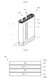
FIG. 1 is an exploded perspective view of a secondary battery according to an exemplary embodiment of the present invention; -
FIG. 2 is a perspective view illustrating a structure in which a finishing tape is adhered to an electrode assembly in the secondary battery shown inFIG. 1 ; -
FIG. 3 is a cross-sectional view illustrating a structure of a finishing tape in the secondary battery shown inFIG. 1 ; and -
FIG. 4 is a cross-sectional view of the secondary battery shown inFIG. 1 . - Referring to
FIGS. 1 and 2 , thesecondary battery 100 according to the embodiment of the present invention includes acase 110, anelectrode assembly 120,finishing tapes cap assembly 150. In addition, aninsulation case 160 may further be provided between theelectrode assembly 120 and thecap assembly 150. - The
case 110 is substantially hexahedral shaped. Thecase 110 has an internal space and a top opening 110a. Thecase 110 may be made of aluminum (Al), iron (Fe) or an alloy thereof. In addition, the inner surface of thecase 110 may be subjected to insulation treatment. Thecase 110 may include agroove 111 formed along the top periphery, so that theinsulation case 160 is to be placed in thegroove 111. In addition, an electrolyte solution with theelectrode assembly 120 may be accommodated in the space of thecase 110. The electrolyte solution is an organic liquid containing a salt injected to allow lithium ions to move between positive and negative electrode plates of theelectrode assembly 120, and may include a non-aqueous organic electrolyte solution having a lithium salt, such as LiPF6, LiBF4, or LiClO4, and a high-purity organic solvent mixed therein, or a polymer electrolyte solution using a polymer electrolyte. - The
electrode assembly 120 is accommodated in the space of thecase 110. Theelectrode assembly 120 includes apositive electrode plate 121 coated with a positive active material (e.g., lithium cobalt oxide (LiCoO2), anegative electrode plate 122 coated with a negative active material (e.g., graphite), and aseparator 123 positioned between thepositive electrode plate 121 and thenegative electrode plate 122 to prevent an electric short and to allow lithium ions to move. Theelectrode assembly 120 is formed by winding a stacked structure of thepositive electrode plate 121, theseparator 123 and thenegative electrode plate 122 multiple times in a substantially jelly-roll configuration. Thepositive electrode plate 121 may be made of aluminum (Al) foil, thenegative electrode plate 122 may be made of a copper (Cu) foil, and theseparator 123 may be made of polyethylene (PE) or polypropylene (PP). - In addition, an upwardly extending
positive electrode lead 125 is connected to the positive electrode plate, and an upwardly extendingnegative electrode lead 124 is connected to the negative electrode plate. Here, thepositive electrode lead 125 may be made of aluminum (Al), and thenegative electrode lead 124 may be made of nickel (Ni). - As described above, the electrolyte solution is injected into the
case 110. During charging and discharging, the electrolyte solution serves as a medium for moving lithium ions generated by an electrochemical reaction taking place between the positive electrode plate and the negative electrode plate within the battery. - The
finishing tapes termination tape 130 formed along thetermination line 120a at which winding of theelectrode assembly 120 ends, and abottom tape 140 wrapping up a bottom end of theelectrode assembly 120. - The
electrode assembly 120 is wound in a circular configuration with the separator interposed between the positive electrode plate and the negative electrode plate, and thetermination tape 130 is attached along thetermination line 120a at which winding of theelectrode assembly 120 ends, as shown, thereby fixing theelectrode assembly 120. Thetermination tape 130 is fixedly compressed to prevent theelectrode assembly 120 from being unwound, thereby allowing theelectrode assembly 120 to be easily placed in thecase 110. Thetermination tape 130 may have the same structure as the conventional tape. However, thetermination tape 130 may have the same structure as thebottom tape 140 as selected by one skilled in the art. - The
bottom tape 140 is configured to entirely wrap up the bottom end of theelectrode assembly 120 to be positioned between theelectrode assembly 120 and thecase 110. Thebottom tape 140 reacts with the electrolyte solution accommodated in thecase 110 to be modified to have adhesiveness, thereby fixing theelectrode assembly 120 into thecase 110 to prevent theelectrode assembly 120 from moving in thecase 110. In addition, thebottom tape 140 prevents the bottom end of theelectrode assembly 120 from making direct contact with thecase 110, thereby preventing an electrical short. - In more detail, the
bottom tape 140 is configured as shown inFIG. 3 . In thebottom tape 140, afirst substrate 141 is formed on onesurface 140a attached to theelectrode assembly 120, and asecond substrate 142 is formed on theother surface 140b attached to thecase 110. - The
first substrate 141 does not react with the electrolyte solution so as not to be dissolved, and forms a base film. In detail, thefirst substrate 141 may be made of polyethylene (PE). Therefore, thefirst substrate 141 prevents theelectrode assembly 120 from making direct contact with thecase 110, thereby preventing an electrical short from occurring in thesecondary battery 100. - Meanwhile, the
second substrate 142 reacts with the electrolyte solution to be modified to have adhesiveness. Thesecond substrate 142 may be made of polystyrene (PS) or oriented PS. After thesecond substrate 142 reacts with the electrolyte solution, thefirst substrate 141 as a base film is adhered to thecase 110, thereby preventing theelectrode assembly 120 from moving in thecase 110. Therefore, it is possible to prevent theelectrode assembly 120 from being damaged due to external impacts. - Other suitable materials may be used, with the proviso that the second substrate is more reactive to the electrolyte solution than the first substrate.
- In addition, the
bottom tape 140 may include a firstadhesive layer 143 to attach thefirst substrate 141 to theelectrode assembly 141 and a secondadhesive layer 144 to attach thefirst substrate 141 and thesecond substrate 142 to each other. The first and secondadhesive layer 144 may be made of acryl. - Therefore, the
secondary battery 100 according to the embodiment of the present invention includes thefirst substrate 141 made of polyethylene (PE) on thebottom tape 140, of the finishingtapes second substrate 142 made of polystyrene (PS) or oriented PS, thereby preventing an electrical short between theelectrode assembly 120 and thecase 110 while preventing theelectrode assembly 120 from moving. - In addition, considering that the electrolyte solution is impregnated, the
first substrate 141 is preferably positioned in theelectrode assembly 120 and thesecond substrate 142 is preferably positioned to face the inner surface of thecase 110. However, according to selection by one skilled in the art, positions of thefirst substrate 141 and thesecond substrate 142 may be changed. - The entire thickness of the
bottom tape 140 is preferably set to 10µm or greater. If the thickness of thebottom tape 140 is 10µm or greater, thebottom tape 140 can advantageously prevent theelectrode assembly 120 from moving by fixing the position of theelectrode assembly 120. In addition, thebottom tape 140 can advantageously prevent an electrical short between theelectrode assembly 120 and thecase 110 by securing an appropriate thickness of thebottom tape 140. - In addition, in the
bottom tape 140, thefirst substrate 141 may be formed to have a thickness in a range of 5 µm to 7 µm. If the thickness of thefirst substrate 141 is 5 µm or greater, reliability in the insulating performance between theelectrode assembly 120 and thecase 110 using thefirst substrate 141 can be maintained. In addition, if the thickness of thefirst substrate 141 is 7 µm or less, the capacity of thesecondary battery 100 can be advantageously achieved by increasing the capacity of theelectrode assembly 120. - In addition, each of the first
adhesive layer 143 and the secondadhesive layer 144 may have a thickness set to 4 µm or less. Since the firstadhesive layer 143 and the secondadhesive layer 144 are formed to have minimum thicknesses so long as they can be coated, lower limits of the firstadhesive layer 143 and the secondadhesive layer 144 are not separately defined. If the thickness of each of the firstadhesive layer 143 and the secondadhesive layer 144 is 4 µm or less, the capacity of thesecondary battery 100 can be advantageously achieved by increasing the capacity of theelectrode assembly 120. - Meanwhile, a height h1 of the
bottom tape 140 is preferably one third (⅓) of a height h of theelectrode assembly 120. If the height h1 of thebottom tape 140 is less than one third (⅓) of the height h of theelectrode assembly 120, the capacity of theelectrode assembly 120 can be advantageously obtained, and ion exchange based on the electrolyte solution can be advantageously achieved. - The
cap assembly 150 is coupled to a top portion of thecan 110. Thecap assembly 150 includes acap plate 151, aninsulation plate 152, aterminal plate 153, anelectrode terminal 154, aninsulation gasket 155 and aplug 156. - The
cap plate 151 is coupled to the opening of thecan 110 and is shaped of a plate having long sides and short sides. In a state in which thecap plate 151 is coupled to the opening of thecan 110, the periphery of thecap plate 151 is welded to seal thecan 110. Thecap plate 151 has ahole 151a to couple theelectrode terminal 154 and an injection hole 151b to inject the electrolyte solution. - The
insulation plate 152 is positioned at a lower portion of thecap plate 151. Theinsulation gasket 155 is coupled to ahole 152a of theinsulation plate 152. In addition, the lower portion of theelectrode terminal 154 penetrates thehole 152a of theinsulation plate 152. - The
terminal plate 153 is positioned at a lower portion of theinsulation plate 152. Theelectrode terminal 154 is coupled to ahole 153a of theterminal plate 153, and theelectrode terminal 154 is electrically connected to thenegative electrode lead 124. - A lower portion of the
electrode terminal 154 protrudes to then penetrate thecap plate 151 and theinsulation plate 152 to be electrically connected to thenegative electrode lead 124. Theinsulation gasket 155 is positioned between theelectrode terminal 154 and thecap plate 151, thereby preventing theelectrode terminal 154 from electrically contacting thecap plate 151. - The
plug 156 is formed to correspond to an electrolyte injection hole of thecap plate 151. Once the electrolyte solution is injected, theplug 156 is fixedly seal by thecap plate 151, thereby preventing the electrolyte solution from leaking. - The
insulation case 160 is coupled to a top portion of theelectrode assembly 120, that is, theopening 110a of thecan 110. In more detail, theinsulation case 160 may be coupled to astep 111 of thecan 110. Lead passingholes insulation case 160 to allow thenegative electrode lead 124 and thepositive electrode lead 125 to penetrate. -
FIG. 4 is a cross-sectional view of the secondary battery shown inFIG. 1 . - Referring to
FIG. 4 , in thesecondary battery 100 including a finishing tape according to an embodiment of the present invention, theelectrode assembly 120 is accommodated in thecase 110. In addition, thebottom tape 140 is positioned between the bottom end of theelectrode assembly 120 and thecase 110. - In addition, although not separately shown, as described above, in the
bottom tape 140, thefirst tape 141 is adhered to theelectrode assembly 120, thereby preventing theelectrode assembly 120 and thecase 110 from being electrically short circuited. - In addition, as described above, the
second tape 142 is adhered to thecase 110, thereby preventing theelectrode assembly 120 from moving in thecase 110. - Although embodiments of the present invention have been described in detail hereinabove, it should be understood that many variations and modifications of the embodiments, which may appear to those skilled in the art, will still fall within the scope of the invention as defined by the appended claims.
Claims (15)
- A secondary battery comprising:a case (110);an electrode assembly (120) in the case;an electrolyte solution in the case; andan insulating tape (130, 140) disposed between the case and the electrode assembly, the insulating tape comprising first and second layers (141, 142), wherein the first layer (141) comprises an insulating and non-adhesive (141) material and the second layer (142) is more reactive to the electrolyte solution than the first layer.
- The secondary battery according to claim 1, wherein the second layer (142) comprises a material that is arranged to react with the electrolyte solution to fix the electrode assembly to an inner surface (110a) of the case.
- The secondary battery according to claim 1 or 2, wherein the insulating tape further comprises a first adhesive layer (144) between the first and second layers (141, 142).
- The secondary battery according to any one of the preceding claims, wherein the insulating tape further comprises an adhesive layer (143) on an outer surface of the first layer (141).
- The secondary battery according to any one of claims 2 to 4, wherein the or each adhesive layer comprises an acrylic adhesive.
- The secondary battery according to any one of claims 2 to 5, wherein the or each adhesive layer has a thickness of 4µm or less.
- The secondary battery according to any one of the preceding claims, wherein the first layer (141) comprises polyethylene PE.
- The secondary battery according to any one of the preceding claims, wherein the second layer (142) comprises polystyrene PS or oriented polystyrene OPS.
- The secondary battery according to any one of the preceding claims, wherein the first layer (141) is formed on a side of the insulating tape facing the electrode assembly.
- The secondary battery according to any one of the preceding claims, wherein the second layer (142) is formed on a side of the insulating tape facing the inner surface of the case.
- The secondary battery according to any one of the preceding claims, wherein the first layer is between 5 µm and 7 µm thick.
- The secondary battery according to any one of the preceding claims, wherein the insulating tape has a thickness of 10 µm or more.
- The secondary battery according to any one of the preceding claims, wherein the insulating tape is wrapped around the bottom end of the electrode assembly.
- The secondary battery of claim 13, wherein the insulating tape extends no more than one third of the way up the electrode assembly.
- The secondary battery of any one of claims 1 to 13, wherein the insulating tape is arranged along a termination line (120a) at which the winding of the electrode assembly ends to prevent the electrode assembly from being unwound.
Applications Claiming Priority (1)
| Application Number | Priority Date | Filing Date | Title |
|---|---|---|---|
| KR1020130123295A KR102121737B1 (en) | 2013-10-16 | 2013-10-16 | Secondary Battery |
Publications (2)
| Publication Number | Publication Date |
|---|---|
| EP2863449A1 true EP2863449A1 (en) | 2015-04-22 |
| EP2863449B1 EP2863449B1 (en) | 2019-06-12 |
Family
ID=49956082
Family Applications (1)
| Application Number | Title | Priority Date | Filing Date |
|---|---|---|---|
| EP14152098.1A Active EP2863449B1 (en) | 2013-10-16 | 2014-01-22 | Secondary battery |
Country Status (4)
| Country | Link |
|---|---|
| US (1) | US9761845B2 (en) |
| EP (1) | EP2863449B1 (en) |
| KR (1) | KR102121737B1 (en) |
| CN (1) | CN104576977B (en) |
Families Citing this family (15)
| Publication number | Priority date | Publication date | Assignee | Title |
|---|---|---|---|---|
| JP6641741B2 (en) * | 2015-06-29 | 2020-02-05 | 三洋電機株式会社 | Rechargeable battery |
| KR20170063192A (en) * | 2015-11-30 | 2017-06-08 | 삼성에스디아이 주식회사 | Secondary battery |
| KR102547065B1 (en) * | 2016-02-29 | 2023-06-23 | 삼성에스디아이 주식회사 | Secondary battery |
| US9772658B1 (en) * | 2016-06-24 | 2017-09-26 | Getac Technology Corporation | Case for protecting battery and electronic device having the same |
| KR102245620B1 (en) * | 2016-08-18 | 2021-04-27 | 삼성에스디아이 주식회사 | Rechargeable battery |
| KR20180028837A (en) * | 2016-09-09 | 2018-03-19 | 삼성에스디아이 주식회사 | Rechargeable battery |
| KR102278993B1 (en) * | 2017-03-20 | 2021-07-20 | 주식회사 엘지에너지솔루션 | Electrode assembly |
| KR102388921B1 (en) * | 2018-01-24 | 2022-04-21 | 삼성에스디아이 주식회사 | Secondary battery and manufacturing method thereof |
| KR102132844B1 (en) * | 2018-07-17 | 2020-07-10 | 삼성에스디아이 주식회사 | Secondary battery |
| CN110190340B (en) | 2019-03-01 | 2024-04-19 | 青海时代新能源科技有限公司 | Secondary battery |
| CN110190339A (en) * | 2019-03-01 | 2019-08-30 | 青海时代新能源科技有限公司 | Secondary cell |
| KR20200106694A (en) | 2019-03-05 | 2020-09-15 | 삼성에스디아이 주식회사 | Secondary battery |
| CN112332040A (en) * | 2020-08-31 | 2021-02-05 | 宁德时代新能源科技股份有限公司 | Battery cell, battery pack, electric device, and method for manufacturing battery cell |
| CN114204133A (en) * | 2021-12-09 | 2022-03-18 | 惠州亿纬锂能股份有限公司 | Method for solving expansion of winding type battery cell |
| CN117413408A (en) * | 2022-03-31 | 2024-01-16 | 宁德新能源科技有限公司 | Electrochemical device and electronic device |
Citations (7)
| Publication number | Priority date | Publication date | Assignee | Title |
|---|---|---|---|---|
| US20060251962A1 (en) * | 2005-04-26 | 2006-11-09 | Samsung Sdi Co., Ltd. | Secondary battery |
| EP2254187A1 (en) * | 2009-05-18 | 2010-11-24 | Samsung SDI Co., Ltd. | Secondary battery and manufacturing method of the same |
| EP2267830A1 (en) * | 2009-06-05 | 2010-12-29 | Samsung SDI Co., Ltd. | Electrode assembly and secondary battery using the same |
| EP2273601A1 (en) * | 2009-07-08 | 2011-01-12 | Samsung SDI Co., Ltd. | Secondary battery |
| EP2375472A1 (en) * | 2010-04-05 | 2011-10-12 | Samsung SDI Co., Ltd. | Secondary battery |
| EP2477252A1 (en) * | 2010-10-04 | 2012-07-18 | LG Chem, Ltd. | Seal tape and secondary battery using same |
| US20130202932A1 (en) * | 2012-02-03 | 2013-08-08 | Hyojung Song | Pouch type battery |
Family Cites Families (6)
| Publication number | Priority date | Publication date | Assignee | Title |
|---|---|---|---|---|
| JP3891047B2 (en) | 2002-06-10 | 2007-03-07 | 松下電器産業株式会社 | battery |
| KR20040042375A (en) | 2002-11-14 | 2004-05-20 | 삼성에스디아이 주식회사 | Jelly-roll electrode assembly and secondary battery therewith |
| KR101285977B1 (en) * | 2006-04-10 | 2013-07-12 | 삼성에스디아이 주식회사 | Eletrode assembly and secondary battery having the same |
| KR101136254B1 (en) * | 2010-05-20 | 2012-04-19 | 삼성에스디아이 주식회사 | Secondary battery |
| US8062787B2 (en) | 2009-09-11 | 2011-11-22 | Samsung Sdi Co., Ltd | Secondary battery and method of manufacturing the secondary battery |
| KR101100948B1 (en) * | 2010-07-29 | 2011-12-29 | 삼성에스디아이 주식회사 | Secondary battery |
-
2013
- 2013-10-16 KR KR1020130123295A patent/KR102121737B1/en active IP Right Grant
-
2014
- 2014-01-22 EP EP14152098.1A patent/EP2863449B1/en active Active
- 2014-02-03 US US14/171,744 patent/US9761845B2/en active Active
- 2014-03-18 CN CN201410100539.4A patent/CN104576977B/en active Active
Patent Citations (7)
| Publication number | Priority date | Publication date | Assignee | Title |
|---|---|---|---|---|
| US20060251962A1 (en) * | 2005-04-26 | 2006-11-09 | Samsung Sdi Co., Ltd. | Secondary battery |
| EP2254187A1 (en) * | 2009-05-18 | 2010-11-24 | Samsung SDI Co., Ltd. | Secondary battery and manufacturing method of the same |
| EP2267830A1 (en) * | 2009-06-05 | 2010-12-29 | Samsung SDI Co., Ltd. | Electrode assembly and secondary battery using the same |
| EP2273601A1 (en) * | 2009-07-08 | 2011-01-12 | Samsung SDI Co., Ltd. | Secondary battery |
| EP2375472A1 (en) * | 2010-04-05 | 2011-10-12 | Samsung SDI Co., Ltd. | Secondary battery |
| EP2477252A1 (en) * | 2010-10-04 | 2012-07-18 | LG Chem, Ltd. | Seal tape and secondary battery using same |
| US20130202932A1 (en) * | 2012-02-03 | 2013-08-08 | Hyojung Song | Pouch type battery |
Also Published As
| Publication number | Publication date |
|---|---|
| EP2863449B1 (en) | 2019-06-12 |
| KR20150044204A (en) | 2015-04-24 |
| KR102121737B1 (en) | 2020-06-11 |
| CN104576977B (en) | 2020-06-02 |
| CN104576977A (en) | 2015-04-29 |
| US9761845B2 (en) | 2017-09-12 |
| US20150104684A1 (en) | 2015-04-16 |
Similar Documents
| Publication | Publication Date | Title |
|---|---|---|
| EP2863449B1 (en) | Secondary battery | |
| KR100686813B1 (en) | Secondary Battery | |
| US8679675B2 (en) | Battery including a member configured to prevent a short circuit | |
| JP4926534B2 (en) | Winding electrode assembly and lithium secondary battery including the same | |
| US8846237B2 (en) | Electrode assembly and secondary battery having the same | |
| US7951492B2 (en) | Secondary battery and electrode plate therefor | |
| KR101379985B1 (en) | Electrode assembly and secondary battery using the same | |
| US8691430B2 (en) | Pouch-type lithium secondary battery having a variable tab | |
| JP5875803B2 (en) | Non-aqueous electrolyte secondary battery and manufacturing method thereof | |
| US10490841B2 (en) | Secondary battery | |
| US10096856B2 (en) | Electrode assembly with tape and electrochemical device comprising the same | |
| EP2602841A1 (en) | Battery | |
| JP5119665B2 (en) | Battery pack | |
| KR101825007B1 (en) | Pouch type secondary battery and method of fabricating the same | |
| KR100601555B1 (en) | Jelly-roll type electrode assembly and Li Secondary battery with the same | |
| KR100624954B1 (en) | Lithum Secondary battery having Jelly-roll type electrode assembly | |
| KR100670431B1 (en) | Li Secondary Battery | |
| KR100670430B1 (en) | Li Secondary Battery | |
| KR20140013132A (en) | Secondary battery | |
| KR100686840B1 (en) | Li Secondary Battery and Manufacturing Method of the same | |
| KR100670432B1 (en) | Li Secondary Battery | |
| KR100601543B1 (en) | Li Secondary Battery | |
| KR20060019768A (en) | Jelly-roll type electrode assembly | |
| CN111630698A (en) | Terminal tape and secondary battery including the same | |
| KR20060112738A (en) | Secondary battery |
Legal Events
| Date | Code | Title | Description |
|---|---|---|---|
| PUAI | Public reference made under article 153(3) epc to a published international application that has entered the european phase |
Free format text: ORIGINAL CODE: 0009012 |
|
| 17P | Request for examination filed |
Effective date: 20140122 |
|
| AK | Designated contracting states |
Kind code of ref document: A1 Designated state(s): AL AT BE BG CH CY CZ DE DK EE ES FI FR GB GR HR HU IE IS IT LI LT LU LV MC MK MT NL NO PL PT RO RS SE SI SK SM TR |
|
| AX | Request for extension of the european patent |
Extension state: BA ME |
|
| R17P | Request for examination filed (corrected) |
Effective date: 20151022 |
|
| RBV | Designated contracting states (corrected) |
Designated state(s): AL AT BE BG CH CY CZ DE DK EE ES FI FR GB GR HR HU IE IS IT LI LT LU LV MC MK MT NL NO PL PT RO RS SE SI SK SM TR |
|
| STAA | Information on the status of an ep patent application or granted ep patent |
Free format text: STATUS: EXAMINATION IS IN PROGRESS |
|
| 17Q | First examination report despatched |
Effective date: 20161125 |
|
| GRAP | Despatch of communication of intention to grant a patent |
Free format text: ORIGINAL CODE: EPIDOSNIGR1 |
|
| STAA | Information on the status of an ep patent application or granted ep patent |
Free format text: STATUS: GRANT OF PATENT IS INTENDED |
|
| RIC1 | Information provided on ipc code assigned before grant |
Ipc: H01M 10/0587 20100101ALN20190111BHEP Ipc: H01M 2/02 20060101AFI20190111BHEP Ipc: H01M 10/04 20060101ALI20190111BHEP Ipc: H01M 2/10 20060101ALI20190111BHEP Ipc: H01M 2/34 20060101ALI20190111BHEP Ipc: H01M 10/0525 20100101ALN20190111BHEP |
|
| INTG | Intention to grant announced |
Effective date: 20190219 |
|
| GRAS | Grant fee paid |
Free format text: ORIGINAL CODE: EPIDOSNIGR3 |
|
| GRAA | (expected) grant |
Free format text: ORIGINAL CODE: 0009210 |
|
| STAA | Information on the status of an ep patent application or granted ep patent |
Free format text: STATUS: THE PATENT HAS BEEN GRANTED |
|
| AK | Designated contracting states |
Kind code of ref document: B1 Designated state(s): AL AT BE BG CH CY CZ DE DK EE ES FI FR GB GR HR HU IE IS IT LI LT LU LV MC MK MT NL NO PL PT RO RS SE SI SK SM TR |
|
| REG | Reference to a national code |
Ref country code: GB Ref legal event code: FG4D |
|
| REG | Reference to a national code |
Ref country code: CH Ref legal event code: EP |
|
| REG | Reference to a national code |
Ref country code: AT Ref legal event code: REF Ref document number: 1143754 Country of ref document: AT Kind code of ref document: T Effective date: 20190615 |
|
| REG | Reference to a national code |
Ref country code: DE Ref legal event code: R096 Ref document number: 602014048053 Country of ref document: DE |
|
| REG | Reference to a national code |
Ref country code: IE Ref legal event code: FG4D |
|
| REG | Reference to a national code |
Ref country code: NL Ref legal event code: MP Effective date: 20190612 |
|
| REG | Reference to a national code |
Ref country code: LT Ref legal event code: MG4D |
|
| PG25 | Lapsed in a contracting state [announced via postgrant information from national office to epo] |
Ref country code: AL Free format text: LAPSE BECAUSE OF FAILURE TO SUBMIT A TRANSLATION OF THE DESCRIPTION OR TO PAY THE FEE WITHIN THE PRESCRIBED TIME-LIMIT Effective date: 20190612 Ref country code: LT Free format text: LAPSE BECAUSE OF FAILURE TO SUBMIT A TRANSLATION OF THE DESCRIPTION OR TO PAY THE FEE WITHIN THE PRESCRIBED TIME-LIMIT Effective date: 20190612 Ref country code: HR Free format text: LAPSE BECAUSE OF FAILURE TO SUBMIT A TRANSLATION OF THE DESCRIPTION OR TO PAY THE FEE WITHIN THE PRESCRIBED TIME-LIMIT Effective date: 20190612 Ref country code: NO Free format text: LAPSE BECAUSE OF FAILURE TO SUBMIT A TRANSLATION OF THE DESCRIPTION OR TO PAY THE FEE WITHIN THE PRESCRIBED TIME-LIMIT Effective date: 20190912 Ref country code: SE Free format text: LAPSE BECAUSE OF FAILURE TO SUBMIT A TRANSLATION OF THE DESCRIPTION OR TO PAY THE FEE WITHIN THE PRESCRIBED TIME-LIMIT Effective date: 20190612 Ref country code: FI Free format text: LAPSE BECAUSE OF FAILURE TO SUBMIT A TRANSLATION OF THE DESCRIPTION OR TO PAY THE FEE WITHIN THE PRESCRIBED TIME-LIMIT Effective date: 20190612 |
|
| PG25 | Lapsed in a contracting state [announced via postgrant information from national office to epo] |
Ref country code: RS Free format text: LAPSE BECAUSE OF FAILURE TO SUBMIT A TRANSLATION OF THE DESCRIPTION OR TO PAY THE FEE WITHIN THE PRESCRIBED TIME-LIMIT Effective date: 20190612 Ref country code: GR Free format text: LAPSE BECAUSE OF FAILURE TO SUBMIT A TRANSLATION OF THE DESCRIPTION OR TO PAY THE FEE WITHIN THE PRESCRIBED TIME-LIMIT Effective date: 20190913 Ref country code: LV Free format text: LAPSE BECAUSE OF FAILURE TO SUBMIT A TRANSLATION OF THE DESCRIPTION OR TO PAY THE FEE WITHIN THE PRESCRIBED TIME-LIMIT Effective date: 20190612 Ref country code: BG Free format text: LAPSE BECAUSE OF FAILURE TO SUBMIT A TRANSLATION OF THE DESCRIPTION OR TO PAY THE FEE WITHIN THE PRESCRIBED TIME-LIMIT Effective date: 20190912 |
|
| REG | Reference to a national code |
Ref country code: AT Ref legal event code: MK05 Ref document number: 1143754 Country of ref document: AT Kind code of ref document: T Effective date: 20190612 |
|
| PG25 | Lapsed in a contracting state [announced via postgrant information from national office to epo] |
Ref country code: PT Free format text: LAPSE BECAUSE OF FAILURE TO SUBMIT A TRANSLATION OF THE DESCRIPTION OR TO PAY THE FEE WITHIN THE PRESCRIBED TIME-LIMIT Effective date: 20191014 Ref country code: SK Free format text: LAPSE BECAUSE OF FAILURE TO SUBMIT A TRANSLATION OF THE DESCRIPTION OR TO PAY THE FEE WITHIN THE PRESCRIBED TIME-LIMIT Effective date: 20190612 Ref country code: CZ Free format text: LAPSE BECAUSE OF FAILURE TO SUBMIT A TRANSLATION OF THE DESCRIPTION OR TO PAY THE FEE WITHIN THE PRESCRIBED TIME-LIMIT Effective date: 20190612 Ref country code: NL Free format text: LAPSE BECAUSE OF FAILURE TO SUBMIT A TRANSLATION OF THE DESCRIPTION OR TO PAY THE FEE WITHIN THE PRESCRIBED TIME-LIMIT Effective date: 20190612 Ref country code: AT Free format text: LAPSE BECAUSE OF FAILURE TO SUBMIT A TRANSLATION OF THE DESCRIPTION OR TO PAY THE FEE WITHIN THE PRESCRIBED TIME-LIMIT Effective date: 20190612 Ref country code: RO Free format text: LAPSE BECAUSE OF FAILURE TO SUBMIT A TRANSLATION OF THE DESCRIPTION OR TO PAY THE FEE WITHIN THE PRESCRIBED TIME-LIMIT Effective date: 20190612 Ref country code: EE Free format text: LAPSE BECAUSE OF FAILURE TO SUBMIT A TRANSLATION OF THE DESCRIPTION OR TO PAY THE FEE WITHIN THE PRESCRIBED TIME-LIMIT Effective date: 20190612 |
|
| PG25 | Lapsed in a contracting state [announced via postgrant information from national office to epo] |
Ref country code: ES Free format text: LAPSE BECAUSE OF FAILURE TO SUBMIT A TRANSLATION OF THE DESCRIPTION OR TO PAY THE FEE WITHIN THE PRESCRIBED TIME-LIMIT Effective date: 20190612 Ref country code: SM Free format text: LAPSE BECAUSE OF FAILURE TO SUBMIT A TRANSLATION OF THE DESCRIPTION OR TO PAY THE FEE WITHIN THE PRESCRIBED TIME-LIMIT Effective date: 20190612 Ref country code: IT Free format text: LAPSE BECAUSE OF FAILURE TO SUBMIT A TRANSLATION OF THE DESCRIPTION OR TO PAY THE FEE WITHIN THE PRESCRIBED TIME-LIMIT Effective date: 20190612 Ref country code: IS Free format text: LAPSE BECAUSE OF FAILURE TO SUBMIT A TRANSLATION OF THE DESCRIPTION OR TO PAY THE FEE WITHIN THE PRESCRIBED TIME-LIMIT Effective date: 20191012 |
|
| REG | Reference to a national code |
Ref country code: DE Ref legal event code: R097 Ref document number: 602014048053 Country of ref document: DE |
|
| PG25 | Lapsed in a contracting state [announced via postgrant information from national office to epo] |
Ref country code: TR Free format text: LAPSE BECAUSE OF FAILURE TO SUBMIT A TRANSLATION OF THE DESCRIPTION OR TO PAY THE FEE WITHIN THE PRESCRIBED TIME-LIMIT Effective date: 20190612 |
|
| PLBE | No opposition filed within time limit |
Free format text: ORIGINAL CODE: 0009261 |
|
| STAA | Information on the status of an ep patent application or granted ep patent |
Free format text: STATUS: NO OPPOSITION FILED WITHIN TIME LIMIT |
|
| PG25 | Lapsed in a contracting state [announced via postgrant information from national office to epo] |
Ref country code: PL Free format text: LAPSE BECAUSE OF FAILURE TO SUBMIT A TRANSLATION OF THE DESCRIPTION OR TO PAY THE FEE WITHIN THE PRESCRIBED TIME-LIMIT Effective date: 20190612 Ref country code: DK Free format text: LAPSE BECAUSE OF FAILURE TO SUBMIT A TRANSLATION OF THE DESCRIPTION OR TO PAY THE FEE WITHIN THE PRESCRIBED TIME-LIMIT Effective date: 20190612 |
|
| 26N | No opposition filed |
Effective date: 20200313 |
|
| PG25 | Lapsed in a contracting state [announced via postgrant information from national office to epo] |
Ref country code: SI Free format text: LAPSE BECAUSE OF FAILURE TO SUBMIT A TRANSLATION OF THE DESCRIPTION OR TO PAY THE FEE WITHIN THE PRESCRIBED TIME-LIMIT Effective date: 20190612 Ref country code: IS Free format text: LAPSE BECAUSE OF FAILURE TO SUBMIT A TRANSLATION OF THE DESCRIPTION OR TO PAY THE FEE WITHIN THE PRESCRIBED TIME-LIMIT Effective date: 20200224 |
|
| PG2D | Information on lapse in contracting state deleted |
Ref country code: IS |
|
| PG25 | Lapsed in a contracting state [announced via postgrant information from national office to epo] |
Ref country code: MC Free format text: LAPSE BECAUSE OF FAILURE TO SUBMIT A TRANSLATION OF THE DESCRIPTION OR TO PAY THE FEE WITHIN THE PRESCRIBED TIME-LIMIT Effective date: 20190612 |
|
| REG | Reference to a national code |
Ref country code: CH Ref legal event code: PL |
|
| REG | Reference to a national code |
Ref country code: BE Ref legal event code: MM Effective date: 20200131 |
|
| PG25 | Lapsed in a contracting state [announced via postgrant information from national office to epo] |
Ref country code: LU Free format text: LAPSE BECAUSE OF NON-PAYMENT OF DUE FEES Effective date: 20200122 |
|
| REG | Reference to a national code |
Ref country code: DE Ref legal event code: R079 Ref document number: 602014048053 Country of ref document: DE Free format text: PREVIOUS MAIN CLASS: H01M0002020000 Ipc: H01M0050100000 |
|
| PG25 | Lapsed in a contracting state [announced via postgrant information from national office to epo] |
Ref country code: LI Free format text: LAPSE BECAUSE OF NON-PAYMENT OF DUE FEES Effective date: 20200131 Ref country code: CH Free format text: LAPSE BECAUSE OF NON-PAYMENT OF DUE FEES Effective date: 20200131 Ref country code: BE Free format text: LAPSE BECAUSE OF NON-PAYMENT OF DUE FEES Effective date: 20200131 |
|
| PG25 | Lapsed in a contracting state [announced via postgrant information from national office to epo] |
Ref country code: IE Free format text: LAPSE BECAUSE OF NON-PAYMENT OF DUE FEES Effective date: 20200122 |
|
| PG25 | Lapsed in a contracting state [announced via postgrant information from national office to epo] |
Ref country code: MT Free format text: LAPSE BECAUSE OF FAILURE TO SUBMIT A TRANSLATION OF THE DESCRIPTION OR TO PAY THE FEE WITHIN THE PRESCRIBED TIME-LIMIT Effective date: 20190612 Ref country code: CY Free format text: LAPSE BECAUSE OF FAILURE TO SUBMIT A TRANSLATION OF THE DESCRIPTION OR TO PAY THE FEE WITHIN THE PRESCRIBED TIME-LIMIT Effective date: 20190612 |
|
| PG25 | Lapsed in a contracting state [announced via postgrant information from national office to epo] |
Ref country code: MK Free format text: LAPSE BECAUSE OF FAILURE TO SUBMIT A TRANSLATION OF THE DESCRIPTION OR TO PAY THE FEE WITHIN THE PRESCRIBED TIME-LIMIT Effective date: 20190612 |
|
| PGFP | Annual fee paid to national office [announced via postgrant information from national office to epo] |
Ref country code: DE Payment date: 20221230 Year of fee payment: 10 |
|
| P01 | Opt-out of the competence of the unified patent court (upc) registered |
Effective date: 20230528 |
|
| PGFP | Annual fee paid to national office [announced via postgrant information from national office to epo] |
Ref country code: GB Payment date: 20231221 Year of fee payment: 11 |
|
| PGFP | Annual fee paid to national office [announced via postgrant information from national office to epo] |
Ref country code: FR Payment date: 20231222 Year of fee payment: 11 |