EP2863111A1 - Lighting device with an optical system for the control of UGR Index and luminance - Google Patents
Lighting device with an optical system for the control of UGR Index and luminance Download PDFInfo
- Publication number
- EP2863111A1 EP2863111A1 EP20140189107 EP14189107A EP2863111A1 EP 2863111 A1 EP2863111 A1 EP 2863111A1 EP 20140189107 EP20140189107 EP 20140189107 EP 14189107 A EP14189107 A EP 14189107A EP 2863111 A1 EP2863111 A1 EP 2863111A1
- Authority
- EP
- European Patent Office
- Prior art keywords
- lighting device
- lenses
- grid
- light source
- optical element
- Prior art date
- Legal status (The legal status is an assumption and is not a legal conclusion. Google has not performed a legal analysis and makes no representation as to the accuracy of the status listed.)
- Granted
Links
- 230000003287 optical effect Effects 0.000 title claims abstract description 38
- 239000002861 polymer material Substances 0.000 claims description 4
- 229920006289 polycarbonate film Polymers 0.000 claims description 2
- 230000000694 effects Effects 0.000 description 5
- 238000005452 bending Methods 0.000 description 3
- 238000009304 pastoral farming Methods 0.000 description 2
- 230000001105 regulatory effect Effects 0.000 description 2
- 230000000630 rising effect Effects 0.000 description 2
- CERQOIWHTDAKMF-UHFFFAOYSA-M Methacrylate Chemical compound CC(=C)C([O-])=O CERQOIWHTDAKMF-UHFFFAOYSA-M 0.000 description 1
- 230000001419 dependent effect Effects 0.000 description 1
- 230000004313 glare Effects 0.000 description 1
- 239000000463 material Substances 0.000 description 1
- 230000002093 peripheral effect Effects 0.000 description 1
- 229920003229 poly(methyl methacrylate) Polymers 0.000 description 1
- 239000004926 polymethyl methacrylate Substances 0.000 description 1
- 230000000284 resting effect Effects 0.000 description 1
Images

Classifications
-
- F—MECHANICAL ENGINEERING; LIGHTING; HEATING; WEAPONS; BLASTING
- F21—LIGHTING
- F21V—FUNCTIONAL FEATURES OR DETAILS OF LIGHTING DEVICES OR SYSTEMS THEREOF; STRUCTURAL COMBINATIONS OF LIGHTING DEVICES WITH OTHER ARTICLES, NOT OTHERWISE PROVIDED FOR
- F21V11/00—Screens not covered by groups F21V1/00, F21V3/00, F21V7/00 or F21V9/00
- F21V11/06—Screens not covered by groups F21V1/00, F21V3/00, F21V7/00 or F21V9/00 using crossed laminae or strips, e.g. grid-shaped louvers; using lattices or honeycombs
-
- F—MECHANICAL ENGINEERING; LIGHTING; HEATING; WEAPONS; BLASTING
- F21—LIGHTING
- F21V—FUNCTIONAL FEATURES OR DETAILS OF LIGHTING DEVICES OR SYSTEMS THEREOF; STRUCTURAL COMBINATIONS OF LIGHTING DEVICES WITH OTHER ARTICLES, NOT OTHERWISE PROVIDED FOR
- F21V5/00—Refractors for light sources
- F21V5/007—Array of lenses or refractors for a cluster of light sources, e.g. for arrangement of multiple light sources in one plane
-
- F—MECHANICAL ENGINEERING; LIGHTING; HEATING; WEAPONS; BLASTING
- F21—LIGHTING
- F21V—FUNCTIONAL FEATURES OR DETAILS OF LIGHTING DEVICES OR SYSTEMS THEREOF; STRUCTURAL COMBINATIONS OF LIGHTING DEVICES WITH OTHER ARTICLES, NOT OTHERWISE PROVIDED FOR
- F21V5/00—Refractors for light sources
- F21V5/04—Refractors for light sources of lens shape
- F21V5/048—Refractors for light sources of lens shape the lens being a simple lens adapted to cooperate with a point-like source for emitting mainly in one direction and having an axis coincident with the main light transmission direction, e.g. convergent or divergent lenses, plano-concave or plano-convex lenses
-
- F—MECHANICAL ENGINEERING; LIGHTING; HEATING; WEAPONS; BLASTING
- F21—LIGHTING
- F21S—NON-PORTABLE LIGHTING DEVICES; SYSTEMS THEREOF; VEHICLE LIGHTING DEVICES SPECIALLY ADAPTED FOR VEHICLE EXTERIORS
- F21S8/00—Lighting devices intended for fixed installation
- F21S8/04—Lighting devices intended for fixed installation intended only for mounting on a ceiling or the like overhead structures
-
- F—MECHANICAL ENGINEERING; LIGHTING; HEATING; WEAPONS; BLASTING
- F21—LIGHTING
- F21Y—INDEXING SCHEME ASSOCIATED WITH SUBCLASSES F21K, F21L, F21S and F21V, RELATING TO THE FORM OR THE KIND OF THE LIGHT SOURCES OR OF THE COLOUR OF THE LIGHT EMITTED
- F21Y2103/00—Elongate light sources, e.g. fluorescent tubes
- F21Y2103/10—Elongate light sources, e.g. fluorescent tubes comprising a linear array of point-like light-generating elements
-
- F—MECHANICAL ENGINEERING; LIGHTING; HEATING; WEAPONS; BLASTING
- F21—LIGHTING
- F21Y—INDEXING SCHEME ASSOCIATED WITH SUBCLASSES F21K, F21L, F21S and F21V, RELATING TO THE FORM OR THE KIND OF THE LIGHT SOURCES OR OF THE COLOUR OF THE LIGHT EMITTED
- F21Y2115/00—Light-generating elements of semiconductor light sources
- F21Y2115/10—Light-emitting diodes [LED]
Definitions
- the present invention relates to a lighting device provided with an optical system for the control of UGR index and luminance.
- the invention is intended, in particular, to provide "dark” effect lamps (i.e. having emission above 65° lower than a predetermined threshold) for interior lighting.
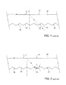
- a prismatic plate of this type is schematically shown in figures 1 and 2 .
- Plate 30 commonly made of transparent methacrylate, has a smooth entry face 31 which is mounted towards the inside of the lighting device (towards the light sources), and a prismatic exit face 32, consisting of cones 33 with angle at the apex of 120°.
- the bases of cones 33 are cut in a hexagonal shape so as to optimize the composition of the structure, which thus proves to be a honeycomb.
- plate 30 works effectively, allowing an excellent control of UGR and luminance at 65° and higher, when the light rays, and in particular the light rays, the most critical to control, grazing on the entry face 31 of plate 30 (i.e. having a high angle of incidence ⁇ , the angle of incidence being the angle between the direction of the light ray impinging on a surface and an axis perpendicular to the surface at the point of incidence of the light ray), pass through "rising" surfaces 34 of the cones ( figure 1 ).
- the light ray emerges from the exit face 32 with a satisfactory (for example lower than the threshold required by the regulations) emission angle ⁇ (angle between the direction of the light ray exiting from a surface and an axis perpendicular to the surface at the exit point of the light ray).
- This condition causes the light intensity higher than 65° not to be zero but have a certain value, which may be critical or not depending on the emitting surface of the device. This is because luminance is defined as the ratio between the light intensity and the apparent emitting surface.
- An object of this invention is to provide a lighting device provided with an optical system for the control of UGR index and luminance, in particular adapted to make “dark” effect lamps, which overcomes the drawbacks of the prior art mentioned herein.
- an object of the invention is to provide a lighting device which enables an efficient control of UGR and luminance even with small emitting surfaces.
- the present invention therefore relates to a lighting device provided with an optical system for the control of UGR index and luminance, in particular to make "dark” effect lamps, as defined in essential terms in the appended claim 1 and, in its additional features, in the dependent claims.
- Figure 3 schematically shows a controlled-emission lighting device 1, in particular adapted to make “dark” effect lamps.
- the lighting device 1 is precisely a device for interior lighting and in particular for workplace lighting.
- the lighting device 1 comprises at least one light source 2, housed in a casing 3, and an optical system 4 for the control of UGR index and luminance.
- the light source 2 may be of various types, for example a row of LEDs.
- the casing 3 may be variously shaped, also according to the use of the lighting device 1 (such as a ceiling lamp).
- the casing 3 is provided with an internal chamber 5, which houses the light source 2 and has an emission aperture 6 delimited by a peripheral edge 7, from which the light emitted by the light source 2 exits.
- the optical system 4 closes the emission aperture 6 and intercepts the emission of the light source 2.
- the optical system 4 comprises a multi-lens optical element 8, formed by a plurality of lenses 9 arranged side-by-side along two directions, and by a grid 10, located on an inner face 11 (facing towards the inside of the lighting device 1 and towards the light source 2) of the optical element 8.
- the optical element 8 is substantially flat and extends between the inner face 11 and an outer face 12, opposite the inner face 11 and facing, in use, towards the outside of the lighting device 1 and thus towards the room to be lighted.
- the optical element 8 is spaced apart from the light source 2, in particular being located at a distance from the light source 2 larger than the thickness (distance between the inner face 11 and the outer face 12) of the optical element 8.
- the optical element 8 is a monolithic element of a transparent polymer material, such as PMMA.
- the lenses 9 are in contact with one another along respective sides.
- Each lens 9 extends along a central axis (optical axis) between an entry surface 13, facing towards the inside of the lighting device 1, and thus towards the light source 2, and an exit surface 14, opposite the entry surface 13 and thus directed towards the outside of the lighting device 1 and towards the room to be lighted.
- the lenses 9 are plano-convex lenses, i.e. having respective opposite surfaces which are a plane surface and a convex surface, respectively, having a predetermined bending radius.
- each lens 9 has the entry surface 13 which is a plane surface, and the exit surface 14 which is a convex surface.
- the entry surfaces 13 form the inner face 11, substantially plane, of the optical element 8; the outer face 12 is formed by a plurality of convex surfaces, consisting of respective exit surfaces 14 of lenses 9.
- the lenses 9 are joined to one another along respective common lateral faces 15.
- the lenses 9 are square lenses, i.e. lenses having a square shape in plan view.
- the grid 10 has a plurality of meshes 16 aligned to respective lenses 9 and delimited by lateral walls 17.
- the grid 10 is arranged on the inner face 11 of the optical element 8 and in contact with the inner face 11; the lateral walls 17 contact the inner face 11 of the optical element 8 and are arranged along the faces 15 which join the lenses 9.
- the lateral walls 17 have respective bottom contact surfaces 21, resting on the inner face 11 of the optical element 8, and respective top free surfaces 22 opposite the contact surfaces 21.
- each lateral wall 17 has a pair of opposite lateral sides 23 which join the contact surfaces 21 and the free surfaces 22.
- the lateral sides 23 have light-absorbing black surfaces, while the free surfaces 22 are diffusive white surfaces having a high reflection coefficient, so as to recover inside the casing 3 the light impinging on the grid 10.
- the free surfaces 22 are made of/coated with a white polymer material having high reflectance, for example an overall reflectance of visible light of 95% or higher.
- the grid 10 is dimensioned so as to limit the angle of incidence ⁇ of the light rays that impinge on the entry surfaces 13 of the lenses 9 (the angle of incidence ⁇ being the angle formed by the direction of a light ray impinging on an entry surface 13 with an axis perpendicular to the entry surface 13 at the point of incidence); precisely, the grid 10 and in particular the lateral walls 17 are dimensioned so that only light rays with angles of incidence ⁇ (with respect to the entry surfaces 13) higher than a minimum threshold ⁇ min impinge on the lenses 9 (on the entry surfaces 13), so as to limit or avoid internal reflections that generally grazing rays (with high angle of incidence) undergo, which are difficult to control.
- the lenses 9 and in particular the exit surfaces 14 thereof are then shaped so as to project the light rays that pass through the grid 10 with emission angles ⁇ (the emission angle ⁇ being the angle between the direction of the light ray exiting from the exit surface 14 and an axis perpendicular to the exit surface 14 at the exit point of the light ray) lower than a threshold value ⁇ Max for example 65° as indicated by the current regulations.
- the lateral walls 17 have a thickness (distance between the opposite lateral sides 23) greater than the height (distance between the contact surface 21 and the free surface 22).
- the lateral walls 17 have a thickness of about 1.5-2.5 mm and a height of about 0.5-1.5 mm.
- the dimensions of meshes 16 depend on the dimensions of the lenses 9, in particular on the length of the sides (in plan view) of the lenses 9, which for example may be about 8-10 mm.
- the bending radius of the lenses 9 (precisely of the exit surfaces 14 thereof) is in general comparable with the length of the sides of the lenses 9, in particular being equal to or slightly greater than the length of the sides of the lenses 9, for example about 8-12 mm.
- the lenses 9 have sides of 9.2 mm and a bending radius of 11 mm.
- the optical element 8 is coupled to or facing towards a diffusive sheet 25, the diffusive sheet, made of suitable light-permeable and diffusive material (such as a polycarbonate film), has the function of making the emission of the lighting device 1 more homogeneous without altering the angles of emission.
- a diffusive sheet 25 the diffusive sheet, made of suitable light-permeable and diffusive material (such as a polycarbonate film), has the function of making the emission of the lighting device 1 more homogeneous without altering the angles of emission.
- the optical system 4 allows obtaining the desired emission (also of the "dark” type) without requiring further optical elements on the light source 2; in particular, if the light source 2 is formed by a plurality of LEDs, the LEDs do not require their own lenses or optics associated with the single LEDs.
- the optical system 4 of the invention in fact operates independently of the light source 2 and can be used with different light sources; therefore, implementing a specific optical system for different light sources or providing the light sources with dedicated optics is not necessary.
Landscapes
- Engineering & Computer Science (AREA)
- General Engineering & Computer Science (AREA)
- Arrangements Of Lighting Devices For Vehicle Interiors, Mounting And Supporting Thereof, Circuits Therefore (AREA)
- Non-Portable Lighting Devices Or Systems Thereof (AREA)
Abstract
Description
- The present invention relates to a lighting device provided with an optical system for the control of UGR index and luminance.
- The invention is intended, in particular, to provide "dark" effect lamps (i.e. having emission above 65° lower than a predetermined threshold) for interior lighting.
- In the field of interior lighting and in particular of workplace lighting, there is the problem of ensuring a controlled emission. Specific regulations also exist in this regard which limit the emission cones of the devices to predetermined values.
- In order to meet the regulatory requirements, it is for example known to use, in technical lighting devices (i.e. intended for lighting workplaces, and in particular offices) where a uniform emitting surface is required, prismatic plates which narrow the emission of the light sources, in particular producing a polar curve complying with the regulatory requirements, namely:
- UGR (Unified Glare Rating): lower than 19;
- luminance at 65° and higher: lower than 3000 cd/m2.
- A prismatic plate of this type is schematically shown in
figures 1 and 2 . -
Plate 30, commonly made of transparent methacrylate, has asmooth entry face 31 which is mounted towards the inside of the lighting device (towards the light sources), and aprismatic exit face 32, consisting ofcones 33 with angle at the apex of 120°. The bases ofcones 33 are cut in a hexagonal shape so as to optimize the composition of the structure, which thus proves to be a honeycomb. - As may be seen in
figures 1 and 2 ,plate 30 works effectively, allowing an excellent control of UGR and luminance at 65° and higher, when the light rays, and in particular the light rays, the most critical to control, grazing on theentry face 31 of plate 30 (i.e. having a high angle of incidence α, the angle of incidence being the angle between the direction of the light ray impinging on a surface and an axis perpendicular to the surface at the point of incidence of the light ray), pass through "rising"surfaces 34 of the cones (figure 1 ). In this case, the light ray emerges from theexit face 32 with a satisfactory (for example lower than the threshold required by the regulations) emission angle β (angle between the direction of the light ray exiting from a surface and an axis perpendicular to the surface at the exit point of the light ray). - If, however, a light ray crosses a "descending"
surface 35 of cones 33 (figure 2 ), then the angle of incidence α is greater than the limit angle and a total internal reflection effect is achieved. The light ray therefore does not pass throughplate 30 but begins to "bounce" insideplate 30. The resulting multiple internal reflections change the orientation of the light ray and when finally there is an incidence on a "rising" surface, the light ray may emerge above 65°. - This condition causes the light intensity higher than 65° not to be zero but have a certain value, which may be critical or not depending on the emitting surface of the device. This is because luminance is defined as the ratio between the light intensity and the apparent emitting surface.
- In conclusion, known systems of the type described above are not able to implement sufficiently clear "cut offs" to make the prismatic plates effectively usable on all devices. In particular, UGR and luminance may exceed the law limits when the emitting surface is very small.
- An object of this invention is to provide a lighting device provided with an optical system for the control of UGR index and luminance, in particular adapted to make "dark" effect lamps, which overcomes the drawbacks of the prior art mentioned herein.
- In particular, an object of the invention is to provide a lighting device which enables an efficient control of UGR and luminance even with small emitting surfaces.
- The present invention therefore relates to a lighting device provided with an optical system for the control of UGR index and luminance, in particular to make "dark" effect lamps, as defined in essential terms in the appended claim 1 and, in its additional features, in the dependent claims.
- The invention is further described in the following non-limiting embodiment examples, with reference to the accompanying figures in which:
-
figures 1 and 2 show a lighting device with emission control obtained, according to the prior art, with a prismatic plate; -
figure 3 is a schematic perspective view of a lighting device with optical system for the control of UGR index and luminance according to the invention; -
figure 4 is a schematic cross-sectional view, with a portion on an enlarged scale, of a detail of the device infigure 3 . -
Figure 3 schematically shows a controlled-emission lighting device 1, in particular adapted to make "dark" effect lamps. - The lighting device 1 is precisely a device for interior lighting and in particular for workplace lighting.
- The lighting device 1 comprises at least one
light source 2, housed in acasing 3, and anoptical system 4 for the control of UGR index and luminance. - The
light source 2 may be of various types, for example a row of LEDs. - The
casing 3 may be variously shaped, also according to the use of the lighting device 1 (such as a ceiling lamp). In general, thecasing 3 is provided with aninternal chamber 5, which houses thelight source 2 and has anemission aperture 6 delimited by aperipheral edge 7, from which the light emitted by thelight source 2 exits. - The
optical system 4 closes theemission aperture 6 and intercepts the emission of thelight source 2. - With reference to
figure 4 , theoptical system 4 comprises a multi-lens optical element 8, formed by a plurality of lenses 9 arranged side-by-side along two directions, and by agrid 10, located on an inner face 11 (facing towards the inside of the lighting device 1 and towards the light source 2) of the optical element 8. - The optical element 8 is substantially flat and extends between the
inner face 11 and anouter face 12, opposite theinner face 11 and facing, in use, towards the outside of the lighting device 1 and thus towards the room to be lighted. - The optical element 8 is spaced apart from the
light source 2, in particular being located at a distance from thelight source 2 larger than the thickness (distance between theinner face 11 and the outer face 12) of the optical element 8. - Advantageously, the optical element 8 is a monolithic element of a transparent polymer material, such as PMMA.
- The lenses 9 are in contact with one another along respective sides.
- Each lens 9 extends along a central axis (optical axis) between an
entry surface 13, facing towards the inside of the lighting device 1, and thus towards thelight source 2, and anexit surface 14, opposite theentry surface 13 and thus directed towards the outside of the lighting device 1 and towards the room to be lighted. - The lenses 9 are plano-convex lenses, i.e. having respective opposite surfaces which are a plane surface and a convex surface, respectively, having a predetermined bending radius.
- In particular, each lens 9 has the
entry surface 13 which is a plane surface, and theexit surface 14 which is a convex surface. - The
entry surfaces 13 form theinner face 11, substantially plane, of the optical element 8; theouter face 12 is formed by a plurality of convex surfaces, consisting ofrespective exit surfaces 14 of lenses 9. - The lenses 9 are joined to one another along respective common
lateral faces 15. - In the preferred embodiment shown, the lenses 9 are square lenses, i.e. lenses having a square shape in plan view.
- The
grid 10 has a plurality ofmeshes 16 aligned to respective lenses 9 and delimited bylateral walls 17. - The
grid 10 is arranged on theinner face 11 of the optical element 8 and in contact with theinner face 11; thelateral walls 17 contact theinner face 11 of the optical element 8 and are arranged along thefaces 15 which join the lenses 9. - In particular, the
lateral walls 17 have respectivebottom contact surfaces 21, resting on theinner face 11 of the optical element 8, and respective topfree surfaces 22 opposite thecontact surfaces 21. - Then, each
lateral wall 17 has a pair of oppositelateral sides 23 which join thecontact surfaces 21 and thefree surfaces 22. - Preferably, the
lateral sides 23 have light-absorbing black surfaces, while thefree surfaces 22 are diffusive white surfaces having a high reflection coefficient, so as to recover inside thecasing 3 the light impinging on thegrid 10. For example, thefree surfaces 22 are made of/coated with a white polymer material having high reflectance, for example an overall reflectance of visible light of 95% or higher. - The
grid 10 is dimensioned so as to limit the angle of incidence α of the light rays that impinge on theentry surfaces 13 of the lenses 9 (the angle of incidence α being the angle formed by the direction of a light ray impinging on anentry surface 13 with an axis perpendicular to theentry surface 13 at the point of incidence); precisely, thegrid 10 and in particular thelateral walls 17 are dimensioned so that only light rays with angles of incidence α (with respect to the entry surfaces 13) higher than a minimum threshold αmin impinge on the lenses 9 (on the entry surfaces 13), so as to limit or avoid internal reflections that generally grazing rays (with high angle of incidence) undergo, which are difficult to control. - The lenses 9 and in particular the
exit surfaces 14 thereof are then shaped so as to project the light rays that pass through thegrid 10 with emission angles β (the emission angle β being the angle between the direction of the light ray exiting from theexit surface 14 and an axis perpendicular to theexit surface 14 at the exit point of the light ray) lower than a threshold value βMax for example 65° as indicated by the current regulations. - In this way, all the light rays that pass through the lenses 9 are refracted at angles of refraction that meet the requirements, in particular being lower than 65°.
- By way of example, the
lateral walls 17 have a thickness (distance between the opposite lateral sides 23) greater than the height (distance between thecontact surface 21 and the free surface 22). For example, thelateral walls 17 have a thickness of about 1.5-2.5 mm and a height of about 0.5-1.5 mm. - The dimensions of
meshes 16 depend on the dimensions of the lenses 9, in particular on the length of the sides (in plan view) of the lenses 9, which for example may be about 8-10 mm. - The bending radius of the lenses 9 (precisely of the
exit surfaces 14 thereof) is in general comparable with the length of the sides of the lenses 9, in particular being equal to or slightly greater than the length of the sides of the lenses 9, for example about 8-12 mm. - In one example, the lenses 9 have sides of 9.2 mm and a bending radius of 11 mm.
- Optionally, the optical element 8 is coupled to or facing towards a
diffusive sheet 25, the diffusive sheet, made of suitable light-permeable and diffusive material (such as a polycarbonate film), has the function of making the emission of the lighting device 1 more homogeneous without altering the angles of emission. - With the
optical system 4 of the invention it is possible to get a clear "cut off" at the desired angle, preventing the total internal reflection. - The
optical system 4 allows obtaining the desired emission (also of the "dark" type) without requiring further optical elements on thelight source 2; in particular, if thelight source 2 is formed by a plurality of LEDs, the LEDs do not require their own lenses or optics associated with the single LEDs. - The
optical system 4 of the invention in fact operates independently of thelight source 2 and can be used with different light sources; therefore, implementing a specific optical system for different light sources or providing the light sources with dedicated optics is not necessary. - Finally, it is understood that further changes and variations may be done to the lighting device described and shown herein without departing from the scope of the appended claims.
Claims (14)
- A controlled-emission lighting device (1), comprising at least one light source (2) and an optical system (4) for the control of UGR index and luminance; characterized in that the optical system (4) comprises a multi-lens optical element (8), formed by a plurality of lenses (9) arranged side-by-side along two directions, and by a grid (10), located on an inner face (11), facing towards the light source (2), of the optical element (8).
- A lighting device according to claim 1, wherein the grid (10) is shaped and dimensioned so as to limit the angle of incidence of the light rays that impinge on respective entry surfaces (13), facing towards the inside of the lighting device (1) and towards the light source (2), of the lenses (9).
- A lighting device according to claim 2, wherein the grid (10) is shaped and dimensioned so that only light rays with angles of incidence greater than a minimum threshold impinge on the entry surfaces (13) of the lenses (9), so as to limit or avoid multiple internal reflections in the optical element (8).
- A lighting device according to one of the preceding claims, wherein the lenses (9) have respective exit surfaces (14) shaped so as to project the light rays with emission angles lower than a threshold value.
- A lighting device according to one of the preceding claims, wherein the lenses (9) are plano-convex lenses, having respective plane entry surfaces (13) facing towards the inside of the lighting device (1) and towards the light source (2); and respective convex exit surfaces (14), opposite to the entry surface (13).
- A lighting device according to claim 5, wherein the optical element (8) has a substantially plane inner face (11), facing towards the light source (2) and formed by the entry surfaces (13) of the lenses (9); and an outer face (12), opposite to the inner face (11) and formed by a plurality of convex surfaces, defined by respective exit surfaces (14) of the lenses (9).
- A lighting device according to one of the preceding claims, wherein the lenses (9) are square lenses, i.e. lenses having a square shape in plan view.
- A lighting device according to one of the preceding claims, wherein the grid (10) has a plurality of meshes (16) aligned to respective lenses (9) and delimited by lateral walls (17).
- A lighting device according to claim 8, wherein each lateral wall (17) has a pair of opposite lateral sides (23) that have respective light-absorbing black surfaces.
- A lighting device according to one of claims 8 or 9, wherein the lenses (9) are joined to one another along respective common lateral faces (15) and the lateral walls (17) of the grid are located along said lateral faces (15).
- A lighting device according to one of the claims 8 to 10, wherein the lateral walls (17) of the grid (10) have respective top free surfaces (22), facing towards the inside of the lighting device (1) and towards the light source (2); said free surfaces (22) being diffusive white surfaces having a high reflection coefficient.
- A lighting device according to claim 11, wherein said free surfaces (22) are made of and/or coated with a white polymer material having high reflectance, for example an overall reflectance of visible light of 95% or higher.
- A lighting device according to one of the preceding claims, wherein the grid (10) is arranged on an inner face (11), facing towards the light source (2), of the optical element (8) and in contact with the inner face (11) of the optical element (8).
- A lighting device according to one of the preceding claims, comprising a diffusive sheet (25), made of a light-permeable and diffusive polymer material, for example a polycarbonate film, which is coupled to or faces the optical element (8).
Applications Claiming Priority (1)
| Application Number | Priority Date | Filing Date | Title |
|---|---|---|---|
| IT001711A ITMI20131711A1 (en) | 2013-10-15 | 2013-10-15 | LIGHTING APPARATUS WITH OPTICAL SYSTEM FOR INDEX UGR AND LUMINANCE CONTROL |
Publications (2)
| Publication Number | Publication Date |
|---|---|
| EP2863111A1 true EP2863111A1 (en) | 2015-04-22 |
| EP2863111B1 EP2863111B1 (en) | 2016-11-30 |
Family
ID=49780175
Family Applications (1)
| Application Number | Title | Priority Date | Filing Date |
|---|---|---|---|
| EP14189107.7A Active EP2863111B1 (en) | 2013-10-15 | 2014-10-15 | Lighting device with an optical system for the control of UGR Index and luminance |
Country Status (2)
| Country | Link |
|---|---|
| EP (1) | EP2863111B1 (en) |
| IT (1) | ITMI20131711A1 (en) |
Families Citing this family (1)
| Publication number | Priority date | Publication date | Assignee | Title |
|---|---|---|---|---|
| DE102020104340A1 (en) | 2020-02-19 | 2021-08-19 | Vossloh-Schwabe Deutschland GbmH | Lighting device |
Citations (3)
| Publication number | Priority date | Publication date | Assignee | Title |
|---|---|---|---|---|
| US20080030974A1 (en) * | 2006-08-02 | 2008-02-07 | Abu-Ageel Nayef M | LED-Based Illumination System |
| EP2357399A1 (en) * | 2010-02-16 | 2011-08-17 | Koito Manufacturing Co., Ltd. | Optical unit |
| EP2461086A1 (en) * | 2009-07-31 | 2012-06-06 | Appotronics Corporation Limited | Illumination device for stage lighting with high light-combining efficiency |
-
2013
- 2013-10-15 IT IT001711A patent/ITMI20131711A1/en unknown
-
2014
- 2014-10-15 EP EP14189107.7A patent/EP2863111B1/en active Active
Patent Citations (3)
| Publication number | Priority date | Publication date | Assignee | Title |
|---|---|---|---|---|
| US20080030974A1 (en) * | 2006-08-02 | 2008-02-07 | Abu-Ageel Nayef M | LED-Based Illumination System |
| EP2461086A1 (en) * | 2009-07-31 | 2012-06-06 | Appotronics Corporation Limited | Illumination device for stage lighting with high light-combining efficiency |
| EP2357399A1 (en) * | 2010-02-16 | 2011-08-17 | Koito Manufacturing Co., Ltd. | Optical unit |
Also Published As
| Publication number | Publication date |
|---|---|
| ITMI20131711A1 (en) | 2015-04-16 |
| EP2863111B1 (en) | 2016-11-30 |
Similar Documents
| Publication | Publication Date | Title |
|---|---|---|
| US8820964B2 (en) | Linear lighting system | |
| EP2378337B1 (en) | Light shaping lens for LED with a light output surface having portions with differing shapes | |
| JP6868016B2 (en) | Lighting system and how to generate light output | |
| KR20160138984A (en) | Asymmetric turning film with multiple light sources | |
| EP2743896A2 (en) | Surveillance device | |
| US8665521B2 (en) | Window system and light guiding film therein | |
| CN110645511A (en) | Optical device and lighting device | |
| TWI579487B (en) | Secondary optical element and light source module | |
| KR20170033932A (en) | Optical device and lighting apparatus including the same | |
| EP2863111B1 (en) | Lighting device with an optical system for the control of UGR Index and luminance | |
| JP5931079B2 (en) | Lighting device, lighting fixture, and lighting system | |
| US20140301086A1 (en) | Optical sheet and lighting device including the same | |
| WO2014027917A1 (en) | Light-emitting diode lamp | |
| JP6678524B2 (en) | Lighting equipment | |
| CN104482501B (en) | Optical element, optical module and lighting device | |
| CN210687896U (en) | Light distribution assembly and lighting lamp | |
| JP7194692B2 (en) | Light output system and lighting unit comprising same | |
| JP6733317B2 (en) | Window lighting equipment | |
| CN216079652U (en) | Lens for lamp and lamp | |
| US20240302024A1 (en) | Optical component for a luminaire | |
| JP5756382B2 (en) | Lighting device | |
| US20230400162A1 (en) | Lighting devices with uplighting with adjustable optics | |
| JP2020095976A (en) | Luminaire | |
| TWI407055B (en) | Illumination device | |
| JP6066564B2 (en) | Lighting device |
Legal Events
| Date | Code | Title | Description |
|---|---|---|---|
| PUAI | Public reference made under article 153(3) epc to a published international application that has entered the european phase |
Free format text: ORIGINAL CODE: 0009012 |
|
| 17P | Request for examination filed |
Effective date: 20141015 |
|
| AK | Designated contracting states |
Kind code of ref document: A1 Designated state(s): AL AT BE BG CH CY CZ DE DK EE ES FI FR GB GR HR HU IE IS IT LI LT LU LV MC MK MT NL NO PL PT RO RS SE SI SK SM TR |
|
| AX | Request for extension of the european patent |
Extension state: BA ME |
|
| R17P | Request for examination filed (corrected) |
Effective date: 20151021 |
|
| RBV | Designated contracting states (corrected) |
Designated state(s): AL AT BE BG CH CY CZ DE DK EE ES FI FR GB GR HR HU IE IS IT LI LT LU LV MC MK MT NL NO PL PT RO RS SE SI SK SM TR |
|
| RIC1 | Information provided on ipc code assigned before grant |
Ipc: F21Y 103/00 20160101ALN20160428BHEP Ipc: F21V 5/04 20060101ALN20160428BHEP Ipc: F21Y 115/10 20160101ALN20160428BHEP Ipc: F21V 5/00 20150101AFI20160428BHEP Ipc: F21S 8/04 20060101ALN20160428BHEP Ipc: F21V 11/06 20060101ALI20160428BHEP |
|
| GRAP | Despatch of communication of intention to grant a patent |
Free format text: ORIGINAL CODE: EPIDOSNIGR1 |
|
| RIC1 | Information provided on ipc code assigned before grant |
Ipc: F21Y 103/00 20160101ALN20160503BHEP Ipc: F21V 5/00 20150101AFI20160503BHEP Ipc: F21V 5/04 20060101ALN20160503BHEP Ipc: F21Y 115/10 20160101ALN20160503BHEP Ipc: F21V 11/06 20060101ALI20160503BHEP Ipc: F21S 8/04 20060101ALN20160503BHEP |
|
| RIC1 | Information provided on ipc code assigned before grant |
Ipc: F21V 5/00 20150101AFI20160525BHEP Ipc: F21V 5/04 20060101ALN20160525BHEP Ipc: F21S 8/04 20060101ALN20160525BHEP Ipc: F21Y 115/10 20160101ALN20160525BHEP Ipc: F21Y 103/00 20160101ALN20160525BHEP Ipc: F21V 11/06 20060101ALI20160525BHEP |
|
| INTG | Intention to grant announced |
Effective date: 20160608 |
|
| GRAS | Grant fee paid |
Free format text: ORIGINAL CODE: EPIDOSNIGR3 |
|
| GRAA | (expected) grant |
Free format text: ORIGINAL CODE: 0009210 |
|
| AK | Designated contracting states |
Kind code of ref document: B1 Designated state(s): AL AT BE BG CH CY CZ DE DK EE ES FI FR GB GR HR HU IE IS IT LI LT LU LV MC MK MT NL NO PL PT RO RS SE SI SK SM TR |
|
| REG | Reference to a national code |
Ref country code: CH Ref legal event code: EP Ref country code: GB Ref legal event code: FG4D |
|
| REG | Reference to a national code |
Ref country code: AT Ref legal event code: REF Ref document number: 850144 Country of ref document: AT Kind code of ref document: T Effective date: 20161215 |
|
| REG | Reference to a national code |
Ref country code: IE Ref legal event code: FG4D |
|
| REG | Reference to a national code |
Ref country code: DE Ref legal event code: R096 Ref document number: 602014005168 Country of ref document: DE |
|
| PG25 | Lapsed in a contracting state [announced via postgrant information from national office to epo] |
Ref country code: LV Free format text: LAPSE BECAUSE OF FAILURE TO SUBMIT A TRANSLATION OF THE DESCRIPTION OR TO PAY THE FEE WITHIN THE PRESCRIBED TIME-LIMIT Effective date: 20161130 |
|
| REG | Reference to a national code |
Ref country code: CH Ref legal event code: NV Representative=s name: HEPP WENGER RYFFEL AG, CH |
|
| REG | Reference to a national code |
Ref country code: LT Ref legal event code: MG4D |
|
| REG | Reference to a national code |
Ref country code: NL Ref legal event code: MP Effective date: 20161130 |
|
| REG | Reference to a national code |
Ref country code: AT Ref legal event code: MK05 Ref document number: 850144 Country of ref document: AT Kind code of ref document: T Effective date: 20161130 |
|
| PG25 | Lapsed in a contracting state [announced via postgrant information from national office to epo] |
Ref country code: SE Free format text: LAPSE BECAUSE OF FAILURE TO SUBMIT A TRANSLATION OF THE DESCRIPTION OR TO PAY THE FEE WITHIN THE PRESCRIBED TIME-LIMIT Effective date: 20161130 Ref country code: LT Free format text: LAPSE BECAUSE OF FAILURE TO SUBMIT A TRANSLATION OF THE DESCRIPTION OR TO PAY THE FEE WITHIN THE PRESCRIBED TIME-LIMIT Effective date: 20161130 Ref country code: GR Free format text: LAPSE BECAUSE OF FAILURE TO SUBMIT A TRANSLATION OF THE DESCRIPTION OR TO PAY THE FEE WITHIN THE PRESCRIBED TIME-LIMIT Effective date: 20170301 Ref country code: NO Free format text: LAPSE BECAUSE OF FAILURE TO SUBMIT A TRANSLATION OF THE DESCRIPTION OR TO PAY THE FEE WITHIN THE PRESCRIBED TIME-LIMIT Effective date: 20170228 |
|
| PG25 | Lapsed in a contracting state [announced via postgrant information from national office to epo] |
Ref country code: FI Free format text: LAPSE BECAUSE OF FAILURE TO SUBMIT A TRANSLATION OF THE DESCRIPTION OR TO PAY THE FEE WITHIN THE PRESCRIBED TIME-LIMIT Effective date: 20161130 Ref country code: AT Free format text: LAPSE BECAUSE OF FAILURE TO SUBMIT A TRANSLATION OF THE DESCRIPTION OR TO PAY THE FEE WITHIN THE PRESCRIBED TIME-LIMIT Effective date: 20161130 Ref country code: PT Free format text: LAPSE BECAUSE OF FAILURE TO SUBMIT A TRANSLATION OF THE DESCRIPTION OR TO PAY THE FEE WITHIN THE PRESCRIBED TIME-LIMIT Effective date: 20170330 Ref country code: ES Free format text: LAPSE BECAUSE OF FAILURE TO SUBMIT A TRANSLATION OF THE DESCRIPTION OR TO PAY THE FEE WITHIN THE PRESCRIBED TIME-LIMIT Effective date: 20161130 Ref country code: RS Free format text: LAPSE BECAUSE OF FAILURE TO SUBMIT A TRANSLATION OF THE DESCRIPTION OR TO PAY THE FEE WITHIN THE PRESCRIBED TIME-LIMIT Effective date: 20161130 Ref country code: PL Free format text: LAPSE BECAUSE OF FAILURE TO SUBMIT A TRANSLATION OF THE DESCRIPTION OR TO PAY THE FEE WITHIN THE PRESCRIBED TIME-LIMIT Effective date: 20161130 Ref country code: HR Free format text: LAPSE BECAUSE OF FAILURE TO SUBMIT A TRANSLATION OF THE DESCRIPTION OR TO PAY THE FEE WITHIN THE PRESCRIBED TIME-LIMIT Effective date: 20161130 |
|
| PG25 | Lapsed in a contracting state [announced via postgrant information from national office to epo] |
Ref country code: NL Free format text: LAPSE BECAUSE OF FAILURE TO SUBMIT A TRANSLATION OF THE DESCRIPTION OR TO PAY THE FEE WITHIN THE PRESCRIBED TIME-LIMIT Effective date: 20161130 |
|
| PG25 | Lapsed in a contracting state [announced via postgrant information from national office to epo] |
Ref country code: DK Free format text: LAPSE BECAUSE OF FAILURE TO SUBMIT A TRANSLATION OF THE DESCRIPTION OR TO PAY THE FEE WITHIN THE PRESCRIBED TIME-LIMIT Effective date: 20161130 Ref country code: EE Free format text: LAPSE BECAUSE OF FAILURE TO SUBMIT A TRANSLATION OF THE DESCRIPTION OR TO PAY THE FEE WITHIN THE PRESCRIBED TIME-LIMIT Effective date: 20161130 Ref country code: RO Free format text: LAPSE BECAUSE OF FAILURE TO SUBMIT A TRANSLATION OF THE DESCRIPTION OR TO PAY THE FEE WITHIN THE PRESCRIBED TIME-LIMIT Effective date: 20161130 Ref country code: CZ Free format text: LAPSE BECAUSE OF FAILURE TO SUBMIT A TRANSLATION OF THE DESCRIPTION OR TO PAY THE FEE WITHIN THE PRESCRIBED TIME-LIMIT Effective date: 20161130 Ref country code: SK Free format text: LAPSE BECAUSE OF FAILURE TO SUBMIT A TRANSLATION OF THE DESCRIPTION OR TO PAY THE FEE WITHIN THE PRESCRIBED TIME-LIMIT Effective date: 20161130 |
|
| PG25 | Lapsed in a contracting state [announced via postgrant information from national office to epo] |
Ref country code: BE Free format text: LAPSE BECAUSE OF FAILURE TO SUBMIT A TRANSLATION OF THE DESCRIPTION OR TO PAY THE FEE WITHIN THE PRESCRIBED TIME-LIMIT Effective date: 20161130 Ref country code: BG Free format text: LAPSE BECAUSE OF FAILURE TO SUBMIT A TRANSLATION OF THE DESCRIPTION OR TO PAY THE FEE WITHIN THE PRESCRIBED TIME-LIMIT Effective date: 20170228 Ref country code: SM Free format text: LAPSE BECAUSE OF FAILURE TO SUBMIT A TRANSLATION OF THE DESCRIPTION OR TO PAY THE FEE WITHIN THE PRESCRIBED TIME-LIMIT Effective date: 20161130 |
|
| REG | Reference to a national code |
Ref country code: DE Ref legal event code: R097 Ref document number: 602014005168 Country of ref document: DE |
|
| PLBE | No opposition filed within time limit |
Free format text: ORIGINAL CODE: 0009261 |
|
| STAA | Information on the status of an ep patent application or granted ep patent |
Free format text: STATUS: NO OPPOSITION FILED WITHIN TIME LIMIT |
|
| REG | Reference to a national code |
Ref country code: FR Ref legal event code: PLFP Year of fee payment: 4 |
|
| 26N | No opposition filed |
Effective date: 20170831 |
|
| PG25 | Lapsed in a contracting state [announced via postgrant information from national office to epo] |
Ref country code: SI Free format text: LAPSE BECAUSE OF FAILURE TO SUBMIT A TRANSLATION OF THE DESCRIPTION OR TO PAY THE FEE WITHIN THE PRESCRIBED TIME-LIMIT Effective date: 20161130 |
|
| PG25 | Lapsed in a contracting state [announced via postgrant information from national office to epo] |
Ref country code: MC Free format text: LAPSE BECAUSE OF FAILURE TO SUBMIT A TRANSLATION OF THE DESCRIPTION OR TO PAY THE FEE WITHIN THE PRESCRIBED TIME-LIMIT Effective date: 20161130 |
|
| REG | Reference to a national code |
Ref country code: CH Ref legal event code: PL |
|
| REG | Reference to a national code |
Ref country code: IE Ref legal event code: MM4A |
|
| PG25 | Lapsed in a contracting state [announced via postgrant information from national office to epo] |
Ref country code: LI Free format text: LAPSE BECAUSE OF NON-PAYMENT OF DUE FEES Effective date: 20171031 Ref country code: CH Free format text: LAPSE BECAUSE OF NON-PAYMENT OF DUE FEES Effective date: 20171031 Ref country code: LU Free format text: LAPSE BECAUSE OF NON-PAYMENT OF DUE FEES Effective date: 20171015 |
|
| PG25 | Lapsed in a contracting state [announced via postgrant information from national office to epo] |
Ref country code: MT Free format text: LAPSE BECAUSE OF NON-PAYMENT OF DUE FEES Effective date: 20171015 |
|
| PG25 | Lapsed in a contracting state [announced via postgrant information from national office to epo] |
Ref country code: IE Free format text: LAPSE BECAUSE OF NON-PAYMENT OF DUE FEES Effective date: 20171015 |
|
| PGFP | Annual fee paid to national office [announced via postgrant information from national office to epo] |
Ref country code: GB Payment date: 20190227 Year of fee payment: 5 |
|
| PG25 | Lapsed in a contracting state [announced via postgrant information from national office to epo] |
Ref country code: HU Free format text: LAPSE BECAUSE OF FAILURE TO SUBMIT A TRANSLATION OF THE DESCRIPTION OR TO PAY THE FEE WITHIN THE PRESCRIBED TIME-LIMIT; INVALID AB INITIO Effective date: 20141015 |
|
| PG25 | Lapsed in a contracting state [announced via postgrant information from national office to epo] |
Ref country code: CY Free format text: LAPSE BECAUSE OF FAILURE TO SUBMIT A TRANSLATION OF THE DESCRIPTION OR TO PAY THE FEE WITHIN THE PRESCRIBED TIME-LIMIT Effective date: 20161130 |
|
| PG25 | Lapsed in a contracting state [announced via postgrant information from national office to epo] |
Ref country code: MK Free format text: LAPSE BECAUSE OF FAILURE TO SUBMIT A TRANSLATION OF THE DESCRIPTION OR TO PAY THE FEE WITHIN THE PRESCRIBED TIME-LIMIT Effective date: 20161130 |
|
| PG25 | Lapsed in a contracting state [announced via postgrant information from national office to epo] |
Ref country code: TR Free format text: LAPSE BECAUSE OF FAILURE TO SUBMIT A TRANSLATION OF THE DESCRIPTION OR TO PAY THE FEE WITHIN THE PRESCRIBED TIME-LIMIT Effective date: 20161130 |
|
| PG25 | Lapsed in a contracting state [announced via postgrant information from national office to epo] |
Ref country code: AL Free format text: LAPSE BECAUSE OF FAILURE TO SUBMIT A TRANSLATION OF THE DESCRIPTION OR TO PAY THE FEE WITHIN THE PRESCRIBED TIME-LIMIT Effective date: 20161130 Ref country code: IS Free format text: LAPSE BECAUSE OF FAILURE TO SUBMIT A TRANSLATION OF THE DESCRIPTION OR TO PAY THE FEE WITHIN THE PRESCRIBED TIME-LIMIT Effective date: 20170330 |
|
| GBPC | Gb: european patent ceased through non-payment of renewal fee |
Effective date: 20191015 |
|
| PG25 | Lapsed in a contracting state [announced via postgrant information from national office to epo] |
Ref country code: GB Free format text: LAPSE BECAUSE OF NON-PAYMENT OF DUE FEES Effective date: 20191015 |
|
| PGFP | Annual fee paid to national office [announced via postgrant information from national office to epo] |
Ref country code: IT Payment date: 20231005 Year of fee payment: 10 Ref country code: FR Payment date: 20231026 Year of fee payment: 10 Ref country code: DE Payment date: 20231027 Year of fee payment: 10 |