JP7194692B2 - Light output system and lighting unit comprising same - Google Patents
Light output system and lighting unit comprising same Download PDFInfo
- Publication number
- JP7194692B2 JP7194692B2 JP2019554632A JP2019554632A JP7194692B2 JP 7194692 B2 JP7194692 B2 JP 7194692B2 JP 2019554632 A JP2019554632 A JP 2019554632A JP 2019554632 A JP2019554632 A JP 2019554632A JP 7194692 B2 JP7194692 B2 JP 7194692B2
- Authority
- JP
- Japan
- Prior art keywords
- lens array
- lens
- light source
- array
- light
- Prior art date
- Legal status (The legal status is an assumption and is not a legal conclusion. Google has not performed a legal analysis and makes no representation as to the accuracy of the status listed.)
- Active
Links
Images


Classifications
-
- G—PHYSICS
- G02—OPTICS
- G02B—OPTICAL ELEMENTS, SYSTEMS OR APPARATUS
- G02B3/00—Simple or compound lenses
- G02B3/0006—Arrays
- G02B3/0037—Arrays characterized by the distribution or form of lenses
- G02B3/0056—Arrays characterized by the distribution or form of lenses arranged along two different directions in a plane, e.g. honeycomb arrangement of lenses
-
- G—PHYSICS
- G02—OPTICS
- G02B—OPTICAL ELEMENTS, SYSTEMS OR APPARATUS
- G02B19/00—Condensers, e.g. light collectors or similar non-imaging optics
- G02B19/0004—Condensers, e.g. light collectors or similar non-imaging optics characterised by the optical means employed
- G02B19/0009—Condensers, e.g. light collectors or similar non-imaging optics characterised by the optical means employed having refractive surfaces only
- G02B19/0014—Condensers, e.g. light collectors or similar non-imaging optics characterised by the optical means employed having refractive surfaces only at least one surface having optical power
-
- G—PHYSICS
- G02—OPTICS
- G02B—OPTICAL ELEMENTS, SYSTEMS OR APPARATUS
- G02B19/00—Condensers, e.g. light collectors or similar non-imaging optics
- G02B19/0033—Condensers, e.g. light collectors or similar non-imaging optics characterised by the use
- G02B19/0047—Condensers, e.g. light collectors or similar non-imaging optics characterised by the use for use with a light source
- G02B19/0061—Condensers, e.g. light collectors or similar non-imaging optics characterised by the use for use with a light source the light source comprising a LED
-
- G—PHYSICS
- G02—OPTICS
- G02B—OPTICAL ELEMENTS, SYSTEMS OR APPARATUS
- G02B3/00—Simple or compound lenses
- G02B3/0006—Arrays
- G02B3/0037—Arrays characterized by the distribution or form of lenses
- G02B3/0062—Stacked lens arrays, i.e. refractive surfaces arranged in at least two planes, without structurally separate optical elements in-between
-
- H—ELECTRICITY
- H01—ELECTRIC ELEMENTS
- H01L—SEMICONDUCTOR DEVICES NOT COVERED BY CLASS H10
- H01L33/00—Semiconductor devices with at least one potential-jump barrier or surface barrier specially adapted for light emission; Processes or apparatus specially adapted for the manufacture or treatment thereof or of parts thereof; Details thereof
- H01L33/48—Semiconductor devices with at least one potential-jump barrier or surface barrier specially adapted for light emission; Processes or apparatus specially adapted for the manufacture or treatment thereof or of parts thereof; Details thereof characterised by the semiconductor body packages
- H01L33/58—Optical field-shaping elements
-
- F—MECHANICAL ENGINEERING; LIGHTING; HEATING; WEAPONS; BLASTING
- F21—LIGHTING
- F21V—FUNCTIONAL FEATURES OR DETAILS OF LIGHTING DEVICES OR SYSTEMS THEREOF; STRUCTURAL COMBINATIONS OF LIGHTING DEVICES WITH OTHER ARTICLES, NOT OTHERWISE PROVIDED FOR
- F21V5/00—Refractors for light sources
- F21V5/002—Refractors for light sources using microoptical elements for redirecting or diffusing light
- F21V5/004—Refractors for light sources using microoptical elements for redirecting or diffusing light using microlenses
-
- F—MECHANICAL ENGINEERING; LIGHTING; HEATING; WEAPONS; BLASTING
- F21—LIGHTING
- F21V—FUNCTIONAL FEATURES OR DETAILS OF LIGHTING DEVICES OR SYSTEMS THEREOF; STRUCTURAL COMBINATIONS OF LIGHTING DEVICES WITH OTHER ARTICLES, NOT OTHERWISE PROVIDED FOR
- F21V5/00—Refractors for light sources
- F21V5/04—Refractors for light sources of lens shape
-
- F—MECHANICAL ENGINEERING; LIGHTING; HEATING; WEAPONS; BLASTING
- F21—LIGHTING
- F21Y—INDEXING SCHEME ASSOCIATED WITH SUBCLASSES F21K, F21L, F21S and F21V, RELATING TO THE FORM OR THE KIND OF THE LIGHT SOURCES OR OF THE COLOUR OF THE LIGHT EMITTED
- F21Y2115/00—Light-generating elements of semiconductor light sources
- F21Y2115/10—Light-emitting diodes [LED]
Description
本発明は、例えばLED光源の出力を処理するための光出力システムに関する。 The present invention relates to light output systems, for example for processing the output of LED light sources.
(1つ又は複数のLED)のLED光源がハウジング内に設けられ、光出力パネルが照明器具内に光源の前方に設けられる、LED照明器具はよく知られている。 LED luminaires are well known in which an LED light source of (one or more LEDs) is provided within a housing and a light output panel is provided within the luminaire in front of the light source.
透過光が望ましくない方向に放射されるのを防ぐために、光出力パネルにプロファイル面(profiled surface)を設けることが知られている。光出力パネルは、例えば、ポリメチルメタクリレート(PMMA)又はポリカーボネート(PC)等のプラスチック又は他の任意の材料のプレートである。 It is known to provide a light output panel with a profiled surface to prevent the transmitted light from being emitted in undesired directions. The light output panel is for example a plate of plastic such as polymethylmethacrylate (PMMA) or polycarbonate (PC) or any other material.
パネルの目的は、透過光がパネルから所望の方向に放射されるようにすることである。さらに、パネルは、色の混合を提供する、及び光源を原因とする画像アーチファクトを低減するために使用されてもよい。 The purpose of the panel is to cause the transmitted light to emanate from the panel in the desired direction. Additionally, panels may be used to provide color mixing and reduce image artifacts caused by light sources.
色の混合を提供する1つのアプローチは、レンズレットのアレイ、例えば、2つのレンズレットアレイのスタックを使用することである。特定のアプローチの1つは、例えば、Dross, O.の"Kohler Integration in Color Mixing Collimators", Proc. Of SPIE Vol. 9571 957109, 2015に述べられている、いわゆるケーラーインテグレーション(Kohler integration)を利用することである。 One approach to providing color mixing is to use an array of lenslets, eg, a stack of two lenslet arrays. One particular approach utilizes the so-called Kohler integration, for example described in Dross, O., "Kohler Integration in Color Mixing Collimators", Proc. Of SPIE Vol. 9571 957109, 2015. That is.
ケーラーインテグレーションは、さまざまな放射色のソースのアレイから均一な色混合ビームを作り出す、又は不均一な単一のソースから光混合を提供する強力な概念(powerful concept)である。 Koehler integration is a powerful concept to create a uniform color-mixed beam from an array of sources of different emission colors, or to provide light mixing from a single non-uniform source.
ケーラーインテグレータ(Kohler integrator)の典型的な例は、図1に描かれるような線形レンズレットアレイである。インテグレータは、屈折率1.5のPMMA等のポリマーで形成されたレンズ本体10を含む。対向する2つの表面は各々、図示のようにピッチp、レンズ半径R、及び球面レンズ中心からの角度が+/-αの、整列されたマイクロレンズのアレイを有する。レンズは凸状である、すなわち、各レンズは、レンズ本体10の中央から外側に向かって湾曲している。レンズの間には、単一プレートのポケットが存在する。組み合わされた2つのレンズプレートの全体の厚さvは、第1のレンズアレイのレンズポケット及び第2のレンズアレイのレンズポケット間の(法線(normal)、最短)距離である。
A typical example of a Kohler integrator is a linear lenslet array as depicted in FIG. The integrator includes a
このタイプのインテグレータは、角度ψによって特徴付けられる。入射ビームが最大角φを有する場合、出射ビームの光は、φ<ψの場合2ψの角度範囲にわたって均一に配光される。 This type of integrator is characterized by an angle ψ. If the incoming beam has a maximum angle φ, the light in the outgoing beam is uniformly distributed over an angular range of 2φ for φ<φ.
コリメート光入力に対するインテグレータの機能は、ペイン12に示されている。第1のレンズレットアレイは、第2のレンズレットアレイの表面に集束し、この表面から広角ビームが放出される。
The function of the integrator for collimated light input is shown in
図1の下部は、ψに必要な値を持つ線形レンズレットアレイの構築を可能にする幾何学的方程式を示している。グラフは、屈折率がレンズパラメータαと図示の式に基づく出力角度ψとの関係にどのように影響するかを示している。 The lower part of FIG. 1 shows the geometric equations that allow the construction of a linear lenslet array with the required values for ψ. The graph shows how the refractive index affects the relationship between the lens parameter α and the output angle ψ according to the equation shown.
図2は、上側のプロットとして50°の半値全幅(FWHM)(すなわち、φ=25°であり、すべての光がこの範囲に制限される(confined))の入射ビームの強度(intensity)対角度(degree)のプロットを示し、ψ=40°(ゆえに、FWHM=80°)のレンズレット表面についての出射ビームの強度対角度のプロットも示す。 FIG. 2 shows the intensity versus angle of an incident beam of 50° full width at half maximum (FWHM) (i.e., φ=25° and all light is confined to this range) as the upper plot. A plot of (degree) is shown, as is a plot of output beam intensity versus angle for a lenslet surface with φ=40° (and therefore FWHM=80°).
この線形ケーラーインテグレータの入力パラメータは、n=1.50(屈折率)、R=0.5mm、ψ=40°である。α、v、p、xの計算値は、α=61.1°、v=0.665mm、p=0.875mm、x=0.258mmである。 The input parameters for this linear Koehler integrator are n=1.50 (refractive index), R=0.5 mm, ψ=40°. Calculated values for α, v, p, x are α=61.1°, v=0.665 mm, p=0.875 mm, x=0.258 mm.
図2は、入射ビームのすべての光が配光される、したがって80°(2ψ)の角度範囲内で混合されることを示している。 FIG. 2 shows that all light of the incident beam is distributed and thus mixed within an angular range of 80° (2ψ).
図3は、入力光が所要の狭い角度範囲に制限されない場合の状況を示している。 FIG. 3 illustrates the situation when the input light is not confined to the required narrow angular range.
図3は、上側のプロットとしてFWHM=120°(すなわち、φ=60°)の入射ビームの強度対角度のプロットを示し、ψ=40°の同じレンズレット表面についての出射ビームの強度対角度のプロットも示す。 FIG. 3 shows a plot of incident beam intensity versus angle for FWHM=120° (i.e., φ=60°) as the top plot, and output beam intensity versus angle for the same lenslet surface with ψ=40°. A plot is also shown.
図3に示されるようにψ<φの場合、光は、レンズアレイからすべての方向に逃げる。角度>ψで逃げる光は混合されず、床又は壁等のターゲット表面にアーチファクト(色混合の減少によるカラーアーチファクト等)を与える可能性がある。 If φ<φ as shown in FIG. 3, light escapes from the lens array in all directions. Light escaping at angles>ψ is not mixed and can give artifacts (such as color artifacts due to reduced color mixing) on target surfaces such as floors or walls.
これは、これらのアーチファクトを回避するために、光がケーラーレンズレットプレートに入る前にコリメートされる必要があることを意味する。斯くして、追加の光学系が必要であり、これは、光システムを望ましくないほど大きな体積/サイズ及び高コストにする。 This means that the light needs to be collimated before entering the Koehler lenslet plate to avoid these artifacts. Thus, additional optics are required, which makes the optical system undesirably bulky/sized and costly.
したがって、良好な光混合を備えた出力ビーム角度の制御を可能にし、低コスト及び低重量の光学部品で達成され得る光学システムが必要である。 Therefore, there is a need for an optical system that allows control of the output beam angle with good light mixing and can be achieved with low cost and low weight optical components.
本発明は、特許請求の範囲により規定される。 The invention is defined by the claims.
本発明の一態様による例によれば、光源位置に設けられるLED光源のための光出力システムであって、当該光出力システムは、
光源位置の方を向く凸レンズを含む、第1のレンズアレイと、
光源位置に対して第1のレンズアレイの反対側にあり、光源位置と逆の方を向く凸レンズを含む、第2のレンズアレイと
を備え、
第1のレンズアレイ及び第2のレンズアレイ間にエアギャップがあり、エアギャップの厚さは、第1のレンズアレイの外面及び第2のレンズアレイの外面間の最大厚さの10%未満である、システムが提供される。
According to an example according to one aspect of the invention, there is provided a light output system for an LED light source provided at a light source location, the light output system comprising:
a first lens array comprising convex lenses facing toward the light source position;
a second lens array opposite the first lens array with respect to the light source position and comprising a convex lens facing away from the light source position;
There is an air gap between the first lens array and the second lens array, and the thickness of the air gap is less than 10% of the maximum thickness between the outer surface of the first lens array and the outer surface of the second lens array. A system is provided.
好ましくは、第1のレンズアレイ及び第2のレンズアレイの全体の厚さは、第2のレンズアレイのレンズピッチ以下である。斯くして、クロストークがさらに相殺又は低減されるというさらに改善された光出力システムが得られる。代替的又は追加的に、光出力システムの所望の品質に応じて、ギャップの位置を選択することにより、光出力システムの特性は調整されることができる。好ましくは、エアギャップは、第1のレンズアレイ又は第2のレンズアレイから全体の厚さの最大25%離れて位置付けられる。 Preferably, the overall thickness of the first lens array and the second lens array is less than or equal to the lens pitch of the second lens array. Thus, a further improved light output system is obtained in which crosstalk is further canceled or reduced. Alternatively or additionally, by selecting the position of the gap, the properties of the light output system can be adjusted according to the desired quality of the light output system. Preferably, the air gap is positioned at most 25% of the total thickness away from the first lens array or the second lens array.
当該出力システムは、本質的にケーラーインテグレーターとして機能し、2つのレンズアレイは互いに反対を向いている。2つのレンズアレイのレンズは、レンズの対を形成するように整列される。しかしながら、エアギャップを設けることは、インテグレーション機能が、低グレアのワイドビームが形成されることを可能にするために、とりわけ事前のコリメーションのない、拡散光で作用することを意味する。エアギャップは、臨界角を超える入射角に対して全反射機能を提供する、角度選択性リフレクタとして機能するものと見なされてもよい。光出力システムは、均一な光出口窓が、魅力的な外観を有して形成されることを可能にする。 The output system essentially functions as a Koehler integrator, with two lens arrays facing each other. The lenses of the two lens arrays are aligned to form lens pairs. However, providing an air gap means that the integration function works with diffuse light, especially without prior collimation, to enable a low glare wide beam to be formed. The air gap may be viewed as acting as an angle-selective reflector, providing a total internal reflection function for angles of incidence exceeding the critical angle. The light output system allows uniform light exit windows to be formed with an attractive appearance.
エアギャップは、第1のレンズアレイにおけるレンズからの屈折光ビームが、対のレンズではない第2のレンズアレイにおけるレンズに渡り得るのを防ぐように狭い。エアギャップは、例えば、0.1mm未満の厚さ、例えば、0.05mm未満の厚さを有し、例えば、0.01mmと薄くてもよい。 The air gap is narrow to prevent refracted light beams from lenses in the first lens array from being able to cross lenses in the second lens array that are not paired. The air gap has, for example, a thickness of less than 0.1 mm, such as a thickness of less than 0.05 mm, and may be as thin as, for example, 0.01 mm.
第1のレンズアレイ及び第2のレンズアレイの(ポケット)表面間の最大厚さvは、0.3mm以上、5mm以下であってもよい。これは、低コストで軽量のレンズシステムが形成されることを可能にする。しかしながら、デザインは、異なる寸法にスケーリングされてもよい。 The maximum thickness v between the (pocket) surfaces of the first lens array and the second lens array may be greater than or equal to 0.3 mm and less than or equal to 5 mm. This allows a low cost and lightweight lens system to be formed. However, the design may be scaled to different dimensions.
各レンズアレイのレンズは、例えば、300μm以上、5mm以下のピッチ、例えば、マイクロスケールシステムに対して300μm以上、500μm以下のピッチ、又はミリメートルスケールシステムに対して0.8mm以上、5mm以下のピッチで配置される。 The lenses of each lens array have a pitch of, for example, 300 μm or more and 5 mm or less, such as a pitch of 300 μm or more and 500 μm or less for microscale systems, or a pitch of 0.8 mm or more and 5 mm or less for millimeter scale systems. placed.
各レンズアレイのレンズは、六角形のグリッドに配置されてもよい。第1及び第2のレンズアレイのレンズは、好ましくは、整列されたレンズの対を形成するために同じレンズピッチを有する。 The lenses of each lens array may be arranged in a hexagonal grid. The lenses of the first and second lens arrays preferably have the same lens pitch to form aligned pairs of lenses.
第1のレンズアレイの各レンズの焦点は、好ましくは、第2のレンズアレイの表面に又は第2のレンズアレイの表面の近くにある。これは、従来のケーラー構造(Kohler configuration)を規定する。 The focal point of each lens of the first lens array is preferably at or near the surface of the second lens array. This defines the traditional Kohler configuration.
エアギャップは、好ましくは、平坦である。各レンズアレイは、エアギャップの一方の側を形成する一方の側に平坦な表面を有し、反対の側にテクスチャード加工されたレンズ表面を有してもよい。これは、一般的に言うと、2つのレンズアレイが平坦である(すなわち、レンズは共通平面から投影する)ことを意味する。しかしながら、ギャップは、レンズアレイの共通(平坦)面と鋭角で延びてもよく、及び/又は外側表面は、レンズが共通平面から投影しないが、依然として相互焦点を有するように(内側/外側に)湾曲されてもよい。また、照明システムの審美的デザインが非平坦な光出力面を必要とする場合、システムは非平坦であってもよい。エアギャップは、2つのレンズアレイのちょうど中間にあってもよい。この場合、2つのレンズアレイは、例えば射出成形によって作られる、同一のプレートとして形成されてもよい。さらに代替的に、エアギャップは、第1及び第2のレンズアレイのいずれか一方の近くに位置付けられてもよい。ギャップが、光源の方を向く第1のレンズアレイの近くに位置付けられる、例えば、第1のレンズアレイから厚さvの最大25%離れて位置付けられることは、2つのレンズプレートが、所望の光学効果を達成するために相互に異なる屈折率を有する材料から作られる場合、この光学効果が、ギャップが第2のレンズアレイの近くに位置付けられる場合よりも顕著、すなわち、増長されるという有利な点を有する。一方、ギャップが第2のレンズアレイの近くに位置付けられる、例えば、第1のレンズアレイから厚さvの少なくとも75%離れて位置付けられる場合、光出力システムは、ギャップの/内の歪み、例えば、表面粗さ又は汚れにそれほどセンシブルではない。 The air gap is preferably flat. Each lens array may have a flat surface on one side forming one side of the air gap and a textured lens surface on the opposite side. Generally speaking, this means that the two lens arrays are flat (ie the lenses project from a common plane). However, the gap may extend at an acute angle with the common (flat) plane of the lens array, and/or the outer surfaces may be oriented (inwardly/outwardly) such that the lenses do not project from the common plane, but still have interfocus. It may be curved. The system may also be non-flat if the aesthetic design of the lighting system calls for a non-flat light output surface. The air gap may be exactly halfway between the two lens arrays. In this case the two lens arrays may be formed as identical plates, for example made by injection moulding. Further alternatively, the air gap may be positioned near either one of the first and second lens arrays. The gap is positioned close to the first lens array facing the light source, e.g. Advantageously, this optical effect is more pronounced, i.e. enhanced, than if the gap were positioned close to the second lens array when made from materials with mutually different refractive indices to achieve the effect. have On the other hand, if the gap is positioned close to the second lens array, e.g., positioned at least 75% of the thickness v away from the first lens array, the light output system will experience distortion in/in the gap, e.g. Less sensitive to surface roughness or dirt.
本発明はまた、
上記で定義された光出力システムと、
光源位置における光源と
を備える照明ユニットを提供する。
The present invention also provides
a light output system as defined above;
and a light source at a light source position.
光源は、例えば、LED又はLED配列(LED arrangement)を含む。光出力は、コリメータを介在させることなく、光出力システムに直接提供されてもよい。LED、又はLED配列の各LEDは、例えば、ランバート光出力強度分布を有する。チップオンボードLEDが、低コストの実装のために使用されてもよい。 The light sources include, for example, LEDs or LED arrangements. The light output may be provided directly to the light output system without an intervening collimator. Each LED of the LED, or LED array, has, for example, a Lambertian light output intensity distribution. Chip-on-board LEDs may be used for low cost implementation.
照明ユニットは、例えば、80°及び100°の間の半値全幅角度を有してもよい。これは、良好な光混合がレンズ配列により提供される、広角の出力ビームを提供する。 The lighting unit may for example have a full width half maximum angle between 80° and 100°. This provides a wide angle output beam with good light mixing provided by the lens arrangement.
照明ユニットは、反射側壁及び反射基部を有するハウジングを備え、光源は、基部に設けられ、光出力システムは、側壁上に設けられてもよい。これは、高効率の光出力を可能にするライトボックス構造を規定する。 The lighting unit may comprise a housing having reflective sidewalls and a reflective base, with a light source provided on the base and a light output system provided on the sidewalls. This defines a lightbox structure that enables highly efficient light output.
以下、本発明の例を添付の図面を参照して詳細に述べる。
本発明は、レンズアレイ間に狭いエアギャップを持つ一対のレンズアレイを有する、LED光源のための光出力システムを提供する。光出力システムは、光混合のための光インテグレーション機能を提供し、エアギャップは、均一なワイドビーム出力が、例えば非コリメート光源から受けるような、広範囲の角度からの入射光についてさえ提供されることを可能にする。 The present invention provides a light output system for an LED light source having a pair of lens arrays with a narrow air gap between the lens arrays. The light output system provides a light integration function for light mixing and the air gap provides a uniform wide beam output even for light incident from a wide range of angles, such as received from a non-collimated light source. enable
図4は、出力システムの一例を示している。 FIG. 4 shows an example of an output system.
第1のレンズアレイ40は、入射光に面する、すなわち、光源位置の方を向く凸レンズ42を含む。第2のレンズアレイ44は、光源位置に対して第1のレンズアレイの反対側にあり、光源位置と逆の方を向く凸レンズ46を含む。第1のレンズアレイ40は、レンズ形状を規定する外面40a及び平坦な内面40bを有する。第2のレンズアレイ44は、レンズ形状を規定する外面44a及び平坦な内面44bを有する。
A
2つのレンズアレイは空気によって囲まれ、第1のアレイ42と第2のアレイ46との間、内面40bと内面44bとの間にはエアギャップ48もある。エアギャップの厚さdgは、第1のレンズアレイ42の外面及び第2のレンズアレイ46の外面間の最大厚さの10%未満である。斯くして、図示のパラメータについて、エアギャップの幅は、0.1(v+2x)未満である。
The two lens arrays are surrounded by air, and there is also an
2つのレンズアレイはケーラーインテグレータとして機能するが、エアギャップによって提供される修正された光学機能を備える。斯くして、2つのレンズアレイのレンズは、レンズの対を形成するように整列される。エアギャップは、第1のレンズアレイにおけるレンズからの屈折光ビームが、対のレンズではない第2のレンズアレイにおけるレンズに渡り得るのを防ぐように狭い。エアギャップは、例えば、0.1mm未満の厚さ、例えば、0.05mm未満の厚さを有し、例えば、0.01mmと薄くてもよい。 The two lens arrays act as Koehler integrators, but with a modified optical function provided by the air gap. Thus, the lenses of the two lens arrays are aligned to form lens pairs. The air gap is narrow to prevent refracted light beams from lenses in the first lens array from being able to cross lenses in the second lens array that are not paired. The air gap has, for example, a thickness of less than 0.1 mm, such as a thickness of less than 0.05 mm, and may be as thin as, for example, 0.01 mm.
図1に示されているものに対応する寸法パラメータが、図4に示されている。 Dimensional parameters corresponding to those shown in FIG. 1 are shown in FIG.
エアギャップは、2つのレンズアレイのちょうど中間にあってもよい。この場合、2つのレンズアレイは、例えば射出成形によって作られる、同一のプレートとして形成されてもよい。 The air gap may be exactly halfway between the two lens arrays. In this case the two lens arrays may be formed as identical plates, for example made by injection moulding.
光路のいくつかの例が図5に示されている。第1の光路のセットは、法線入射角(φ=0)における平行ビームとして示され、第2の光路のセットは、大きな入射角(φ=65°)における平行ビームとして示されている。 Some examples of optical paths are shown in FIG. A first set of optical paths is shown as parallel beams at normal incidence (φ=0) and a second set of optical paths is shown as parallel beams at large angles of incidence (φ=65°).
垂直入射光線は、90%以上の透過があるように、二重層構造全体を介して容易に透過される。約60°よりも大きい角度を有する入射光線は、エアギャップにおける光線の全反射によって非常に低い透過率、したがって高い反射率を有する。高角度は、例えばライトボックスデザインの側壁及び基部において散漫散乱を提供することにより、光学システム内で再利用されることができる。最終結果は、高角においては非常に限られた強度しか持たないビーム形状である。このデザインは、特にワイドビームデザイン(FWHMが80°~100°)に特に適している。 A normal incident ray is easily transmitted through the entire bilayer structure, with a transmission of 90% or greater. Incident rays with angles greater than about 60° have very low transmission and therefore high reflectance due to total internal reflection of the rays in the air gap. High angles can be reused within the optical system, for example, by providing diffuse scattering at the sidewalls and base of the lightbox design. The end result is a beam shape with very limited intensity at high angles. This design is particularly suitable for wide beam designs (FWHM between 80° and 100°).
斯くして、エアギャップは、インテグレーション機能が、低グレアのワイドビームが形成されることを可能にするために、とりわけ事前のコリメーションのない、拡散光で作用することを意味する。光出力システムは、均一な光出口窓が、魅力的な外観を有して形成されることを可能にする。 Thus, the air gap means that the integration function works with diffuse light, especially without prior collimation, to enable a low glare wide beam to be formed. The light output system allows uniform light exit windows to be formed with an attractive appearance.
レンズアレイは、線形構造として形成されてもよい。斯くして、図5(及び図6)は3Dレンズのアレイを示すが、レンズは、これらレンズの長さに沿って一定の断面を持つ押出線形構造であることを意味する、2Dであってもよい。この場合、ビーム整形又は色混合は一方向にだけであるが、3D構造は、すべての方向でビーム形状を制御することができる。 A lens array may be formed as a linear structure. Thus, although FIG. 5 (and FIG. 6) show an array of 3D lenses, the lenses are 2D, meaning they are extruded linear structures with a constant cross-section along the length of the lenses. good too. In this case the beam shaping or color mixing is only in one direction, but the 3D structure can control the beam shape in all directions.
図6は、中央にLED光源64を備える基部62と、光出口窓を形成する、側壁66及び上述の光学システム68とを含む、単純なライトボックスを示している。左側に側面図が示され、右側に上面図が示されている。
FIG. 6 shows a simple light box including a base 62 with a central
基部及び側壁は、拡散反射面(例えば、白色)を有する。ライトボックスは、例えばランバート放射プロファイルを持つ2mm x 2mmの、単一のLEDのみを含んでもよい。しかしながら、1色又は複数の色のLEDのアレイが使用されてもよい。LED光出力は、コリメータを介在させることなく、光出力システム68に直接提供される。チップオンボードLEDが、低コストの実装のために使用されてもよい。
The base and sidewalls have a diffusely reflective surface (eg, white). The light box may contain only a single LED, for example 2 mm x 2 mm with a Lambertian emission profile. However, arrays of LEDs of one or more colors may be used. The LED light output is provided directly to
光出口窓68のレンズはテッセレーションされ(tessellated)、この目的のために、六角形のグリッドを形成する六角形のレンズレットが使用されてもよい。第1及び第2のレンズアレイのレンズは、好ましくは、整列されたレンズの対を形成するために同じレンズピッチを有し、これは、同一のレンズアレイが使用されてもよいことを意味する。
The lenses of the
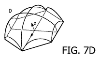
図7は、例えば第1のレンズレットのアレイのための、ひとつの可能なレンズレットデザインを示している。図7Aは、(1つの六角形の面を目いっぱい(full on)示し、2つの他の面を斜めから示す)第1の側面図を示し、図7Bは、平面図を示し、図7Cは、(2つの六角形の面を目いっぱいにではなく示す)第2の側面図を示し、図7Dは、斜視図を示す。 FIG. 7 shows one possible lenslet design, for example for the first array of lenslets. FIG. 7A shows a first side view (one hexagon face shown full on and two other faces shown obliquely), FIG. 7B shows a plan view, and FIG. , shows a second side view (not showing the two hexagonal faces full), and FIG. 7D shows a perspective view.
各レンズは、平面図において六角形に面取りされた(truncated)(半径Rの)球面レンズ表面を有する。 Each lens has a spherical lens surface (of radius R) that is hexagonally truncated in plan view.
この例の六角形の幾何学的形状は、n=1.50(屈折率)、R=1.0mm、ψ=60°のパラメータを使用して規定される。これらのパラメータがα、v、p、xを計算するために使用され、結果は以下の通りである。
α=75.5°
v=0.620mm
p=1.936mm
x=0.749mm
The hexagonal geometry in this example is defined using parameters of n=1.50 (refractive index), R=1.0 mm, ψ=60°. These parameters were used to calculate α, v, p, x and the results are as follows.
α=75.5°
v=0.620mm
p = 1.936mm
x=0.749 mm
エアギャップの幅は、0.01mmである。これらのデータから、全体の厚さvは、第1のレンズアレイのレンズレットのピッチpより小さいという結果になる。 The width of the air gap is 0.01 mm. From these data it follows that the total thickness v is less than the pitch p of the lenslets of the first lens array.
図8は、直交する2つの軸におけるレンズピッチを示し、光出力システムの斜視図を示している。 FIG. 8 shows the lens pitch in two orthogonal axes and shows a perspective view of the light output system.
これらの寸法は、ひとつの実装例の一般的なスケールの一例を示している。 These dimensions are an example of a typical scale for one implementation.
より一般的には、第1のレンズアレイの最も外側の表面と第2のレンズアレイの最も外側の表面の間の最大厚さ(すなわち、v+2x)は、0.4mm以上、5mm以下であってもよい。これは、低コストで軽量のレンズシステムが形成されることを可能にする。しかしながら、デザインは、異なる寸法にスケーリングされてもよい。 More generally, the maximum thickness (i.e., v+2x) between the outermost surface of the first lens array and the outermost surface of the second lens array is 0.4 mm or more and 5 mm or less. good too. This allows a low cost and lightweight lens system to be formed. However, the design may be scaled to different dimensions.
各レンズアレイのレンズは、例えば、300μm以上、5mm以下の(図8に示されるような)ピッチ、例えば、マイクロスケールシステムに対して300μm以上、500μm以下のピッチ、又はミリメートルスケールシステムに対して0.8mm以上、5mm以下のピッチで配置される。これら2つのサブ範囲の間の任意のサイズ範囲も使用されてもよい。 The lenses of each lens array have a pitch of, for example, ≧300 μm and ≦5 mm (as shown in FIG. 8), for example, a pitch of ≧300 μm and ≦500 μm for micro-scale systems, or 0 for millimeter-scale systems. They are arranged at a pitch of 8 mm or more and 5 mm or less. Any size range between these two subranges may also be used.
光出力ユニットの全体的な面積は、例えば、10cm2から1000cm2の範囲内である。
The overall area of the light output unit is, for example, in the
図9は、システムの強度分布を示している。0°の角度方向(例えば、天井に配置されたライトボックスについて鉛直下方)にピーク強度I0がある。約60°より大きい視野角について、(I0と比較して)非常に低い強度しか存在しない。 FIG. 9 shows the intensity distribution of the system. There is a peak intensity I0 at an angular direction of 0° (eg, vertically downward for a ceiling-mounted light box). There is very low intensity (compared to I0) for viewing angles greater than about 60°.
図10は、さまざまな視野角における光学窓全体の輝度を示している。 FIG. 10 shows the brightness across the optical window at various viewing angles.
図10Aは、視野角0°における輝度を示し、図10Bは、視野角30°における輝度を示し、図10Cは、視野角70°における輝度を示す。 10A shows the luminance at a viewing angle of 0°, FIG. 10B shows the luminance at a viewing angle of 30°, and FIG. 10C shows the luminance at a viewing angle of 70°.
均一な面照明の印象を与える規則的なドットパターンが見える。 A regular dot pattern is visible that gives the impression of uniform surface illumination.
図11A~11Bは、構造内の異なるエアギャップ48の位置及びレンズ材料の異なる屈折率n1、n2、n3についての、第1のレンズアレイ40及び第2のレンズアレイ44を備える構造を通る光線経路に対する効果を概略的に示す。図示されるように、非屈折光線70は、屈折率n1を有する第1のレンズアレイ40に入り、屈折光線70aとして伝播する。エアギャップ48を横切った後、当該光線は、第2のレンズアレイに入り、第2のレンズアレイの材料の屈折率に応じて、該光線が第1のレンズアレイによって屈折された場合よりも多く(すなわち、n2>n1)、等しく(すなわち、n1=n1)、又は少なく(すなわち、n3<n1)屈折される。図に示されるように、エアギャップの位置(及び使用される材料の屈折率)に応じた第2のレンズアレイを出る光線のシフト位置の効果Δyは明白である。図11Aにおいて、エアギャップは、第1のレンズアレイ40から25% * v未満、すなわち、約15% * vに存在し、効果は増長される。図11Bにおいて、エアギャップは、第1のレンズアレイ40から75% * vを超えて、すなわち、約85% * vに存在し、光線経路は、汚れ及び/又はエアギャップ表面の歪みにそれほどセンシブルではない。
11A-11B show ray paths through a structure comprising a
光出力システムの外形、したがってシステムを使用するライトボックスは、任意の所望の形状を有することができる。 The profile of the light output system, and thus the light box in which it is used, can have any desired shape.
照明システムは、例えば、オフィス又は他の部屋を照明するための照明器具であり、その場合、照明器具は、天井の凹部に若しくは天井の表面に対して取り付けられてもよく、又は天井から吊り下げられてもよい。この場合、光出力システムは照明器具の下側を形成し、該下側を通って、光が照明器具の光源からオフィスに放射される。照明器具からの光は、鉛直下方向に放射されるだけでなく、所望のワイドビームを形成するために鉛直方向とある角度を囲む方向にも放射される。斯くして、照明器具は、照明器具自体の寸法よりも遥かに大きくし得る領域を照らす。照明の最大角度がまた、照明器具からある距離にいる人々にとっての不都合を回避するために設けられる。斯くして、典型的には、複数の照明器具が天井にわたって配置され、各照明器具は、該照明器具の下のオフィスの一部を照らし、天井の表面と小さな角度を囲む光放射が回避される。 A lighting system is, for example, a luminaire for illuminating an office or other room, where the luminaire may be mounted in a recess in the ceiling or against the surface of the ceiling, or suspended from the ceiling. may be In this case, the light output system forms the underside of the luminaire through which light is emitted from the light source of the luminaire into the office. Light from a luminaire is not only emitted vertically downward, but also around an angle with the vertical to form the desired wide beam. Thus, the luminaire illuminates an area that can be much larger than the dimensions of the luminaire itself. A maximum angle of illumination is also provided to avoid inconvenience for people at some distance from the lighting fixture. Thus, typically a plurality of luminaires are placed across the ceiling, each illuminating a portion of the office below the luminaire, avoiding light radiation around small angles with the surface of the ceiling. be.
開示された実施形態に対する他の変更は、図面、開示、及び添付の特許請求の範囲の研究から、クレームされた発明を実施する際に当業者によって理解され、達成され得る。特許請求の範囲において、「含む(comprising)」という単語は他の要素又はステップを排除するものではなく、不定冠詞「a」又は「an」は複数を除外しない。特定の手段が相互に異なる従属請求項に列挙されているという単なる事実は、これらの手段の組み合わせが有利に使用できないことを示すものではない。請求項中の参照符号は、範囲を限定するものとして解釈されるべきではない。 Other modifications to the disclosed embodiments can be understood and effected by those skilled in the art in practicing the claimed invention, from a study of the drawings, the disclosure, and the appended claims. In the claims, the word "comprising" does not exclude other elements or steps, and the indefinite articles "a" or "an" do not exclude a plurality. The mere fact that certain measures are recited in mutually different dependent claims does not indicate that a combination of these measures cannot be used to advantage. Any reference signs in the claims should not be construed as limiting the scope.
Claims (14)
前記光源位置の方を向く凸レンズを含む、第1のレンズアレイと、
前記光源位置に対して前記第1のレンズアレイの反対側にあり、前記光源位置と逆の方を向く凸レンズを含む、第2のレンズアレイと
を備え、
前記第1のレンズアレイ及び前記第2のレンズアレイ間にエアギャップがあり、前記エアギャップの厚さは、前記第1のレンズアレイの外面及び前記第2のレンズアレイの外面間の最大厚さの10%未満であり、
前記第1のレンズアレイのレンズポケット及び前記第2のレンズアレイのレンズポケット間の距離である、組み合わされた前記第1のレンズアレイ及び前記第2のレンズアレイの全体の厚さは、前記第2のレンズアレイのレンズピッチ以下である、システム。 A light output system for an LED light source provided at a light source location, the light output system comprising:
a first lens array comprising a convex lens facing the light source position;
a second lens array opposite the first lens array with respect to the light source position and comprising a convex lens facing away from the light source position;
There is an air gap between the first lens array and the second lens array, and the thickness of the air gap is the maximum thickness between the outer surface of the first lens array and the outer surface of the second lens array. is less than 10% of
The total thickness of the combined first lens array and the second lens array, which is the distance between the lens pockets of the first lens array and the lens pockets of the second lens array, is A system that is less than or equal to the lens pitch of a lens array of 2.
前記光源位置における光源と
を備える、照明ユニット。 a light output system according to any one of claims 1 to 9;
and a light source at the light source position.
Applications Claiming Priority (3)
| Application Number | Priority Date | Filing Date | Title |
|---|---|---|---|
| EP17164536.9 | 2017-04-03 | ||
| EP17164536 | 2017-04-03 | ||
| PCT/EP2018/057716 WO2018184905A1 (en) | 2017-04-03 | 2018-03-27 | Optical output system and lighting unit comprising the system |
Publications (3)
| Publication Number | Publication Date |
|---|---|
| JP2020516040A JP2020516040A (en) | 2020-05-28 |
| JP2020516040A5 JP2020516040A5 (en) | 2021-05-06 |
| JP7194692B2 true JP7194692B2 (en) | 2022-12-22 |
Family
ID=58698929
Family Applications (1)
| Application Number | Title | Priority Date | Filing Date |
|---|---|---|---|
| JP2019554632A Active JP7194692B2 (en) | 2017-04-03 | 2018-03-27 | Light output system and lighting unit comprising same |
Country Status (5)
| Country | Link |
|---|---|
| US (1) | US11294104B2 (en) |
| EP (1) | EP3607243A1 (en) |
| JP (1) | JP7194692B2 (en) |
| CN (1) | CN110476089B (en) |
| WO (1) | WO2018184905A1 (en) |
Families Citing this family (1)
| Publication number | Priority date | Publication date | Assignee | Title |
|---|---|---|---|---|
| ES2895071T3 (en) * | 2018-05-30 | 2022-02-17 | Depixus | Multi-channel close-up imaging device |
Citations (2)
| Publication number | Priority date | Publication date | Assignee | Title |
|---|---|---|---|---|
| JP2012527111A (en) | 2009-05-12 | 2012-11-01 | フィリップス ルミレッズ ライティング カンパニー リミテッド ライアビリティ カンパニー | LED lamps that produce glitter |
| WO2015172794A1 (en) | 2014-05-13 | 2015-11-19 | Coelux Srl | Light source and sunlight imitating lighting system |
Family Cites Families (25)
| Publication number | Priority date | Publication date | Assignee | Title |
|---|---|---|---|---|
| US5187599A (en) * | 1990-02-01 | 1993-02-16 | Sharp Kabushiki Kaisha | Display including two microlens arrays with unequal focal lengths and congruent focal points |
| KR100272328B1 (en) | 1993-12-22 | 2001-02-01 | 이중구 | Air gap adjusting apparatus for lens |
| CN1132136C (en) | 1995-12-22 | 2003-12-24 | 皇家菲利浦电子有限公司 | Picture display device with two microlens arrays |
| US6069739A (en) * | 1998-06-30 | 2000-05-30 | Intel Corporation | Method and lens arrangement to improve imaging performance of microlithography exposure tool |
| US6507441B1 (en) | 2000-10-16 | 2003-01-14 | Optid, Optical Identification Technologies Ltd. | Directed reflectors and systems utilizing same |
| JP2006505830A (en) * | 2002-11-07 | 2006-02-16 | ソニー インターナショナル (ヨーロッパ) ゲゼルシャフト ミット ベシュレンクテル ハフツング | Lighting device for projector system |
| WO2005083317A1 (en) | 2004-02-20 | 2005-09-09 | Koninklijke Philips Electronics N.V. | A translucent lighting panel, a luminaire, and a method of manufacturing a panel |
| EP1736803A1 (en) | 2004-04-13 | 2006-12-27 | Matsushita Electric Industrial Co., Ltd. | Condensing element and solid state imaging device |
| US20100039819A1 (en) * | 2006-12-29 | 2010-02-18 | Koninklijke Philips Electronics N.V. | Floodlight with tiltable beam |
| TW201024065A (en) * | 2008-12-18 | 2010-07-01 | E Pin Optical Industry Co Ltd | Array optical glass lens module and method of manufacturing the same |
| US8444295B2 (en) * | 2009-06-05 | 2013-05-21 | Prism Projection, Inc. | Optical system for theatrical and stage lighting |
| KR101184449B1 (en) * | 2009-12-28 | 2012-09-21 | 제일모직주식회사 | Patterned light guide panel, method for preparing thereof and lcd back light unit using the same |
| US9423533B2 (en) * | 2010-04-26 | 2016-08-23 | Guardian Industries Corp. | Patterned glass cylindrical lens arrays for concentrated photovoltaic systems, and/or methods of making the same |
| US9184199B2 (en) * | 2011-08-01 | 2015-11-10 | Lytro, Inc. | Optical assembly including plenoptic microlens array |
| KR200470346Y1 (en) * | 2012-05-30 | 2013-12-11 | 씨제이제일제당 (주) | Multipurpose Box |
| ITVI20120134A1 (en) * | 2012-06-05 | 2013-12-06 | Beghelli Spa | ADJUSTABLE BRIGHT OPTIONAL LIGHTING SYSTEM FOR LED LIGHTING DEVICES |
| US10533726B2 (en) * | 2014-06-26 | 2020-01-14 | Signify Holding B.V. | Optical arrangement, lighting device and illumination method |
| JP6634447B2 (en) * | 2014-10-27 | 2020-01-22 | ルミレッズ ホールディング ベーフェー | Directional light emitting device and method of manufacturing the same |
| DE102014116180A1 (en) | 2014-11-06 | 2016-05-12 | Lisa Dräxlmaier GmbH | lighting device |
| US10317579B2 (en) * | 2015-01-19 | 2019-06-11 | Signify Holding B.V. | Optical device with a collimator and lenslet arrays |
| US9881529B2 (en) * | 2015-06-12 | 2018-01-30 | Innolux Corporation | Display device and operating method thereof |
| US10012834B2 (en) * | 2016-03-08 | 2018-07-03 | Microsoft Technology Licensing, Llc | Exit pupil-forming display with reconvergent sheet |
| WO2018086980A1 (en) | 2016-11-14 | 2018-05-17 | Philips Lighting Holding B.V. | Led beam shaping |
| GB201805275D0 (en) | 2018-03-29 | 2018-05-16 | Archangel Lightworks Ltd | Wide aperture optical communications |
| CN209029374U (en) | 2018-12-20 | 2019-06-25 | 广州美锐健康产业股份有限公司 | Multispectral Sony ericsson mobile comm ab and multispectral radiation source |
-
2018
- 2018-03-27 JP JP2019554632A patent/JP7194692B2/en active Active
- 2018-03-27 US US16/493,042 patent/US11294104B2/en active Active
- 2018-03-27 WO PCT/EP2018/057716 patent/WO2018184905A1/en unknown
- 2018-03-27 EP EP18714480.3A patent/EP3607243A1/en active Pending
- 2018-03-27 CN CN201880023217.0A patent/CN110476089B/en active Active
Patent Citations (2)
| Publication number | Priority date | Publication date | Assignee | Title |
|---|---|---|---|---|
| JP2012527111A (en) | 2009-05-12 | 2012-11-01 | フィリップス ルミレッズ ライティング カンパニー リミテッド ライアビリティ カンパニー | LED lamps that produce glitter |
| WO2015172794A1 (en) | 2014-05-13 | 2015-11-19 | Coelux Srl | Light source and sunlight imitating lighting system |
Also Published As
| Publication number | Publication date |
|---|---|
| US20200018873A1 (en) | 2020-01-16 |
| CN110476089A (en) | 2019-11-19 |
| JP2020516040A (en) | 2020-05-28 |
| WO2018184905A1 (en) | 2018-10-11 |
| CN110476089B (en) | 2022-03-11 |
| US11294104B2 (en) | 2022-04-05 |
| EP3607243A1 (en) | 2020-02-12 |
Similar Documents
| Publication | Publication Date | Title |
|---|---|---|
| KR102105065B1 (en) | Light source and sunlight imitating lighting system | |
| US7722224B1 (en) | Illuminating device incorporating a high clarity scattering layer | |
| KR102189535B1 (en) | Artificial lighting system for simulating a natural lighting | |
| JP6157456B2 (en) | lighting equipment | |
| KR20150084024A (en) | Artificial illumination device for generating natural light | |
| KR20120052289A (en) | Free form lighting module | |
| KR20170008262A (en) | Chromatic mirror, chromatic panel and applications thereof | |
| EP3215788B1 (en) | Troffer luminaire | |
| JP2022527488A (en) | Sun sky imitation lighting device | |
| CN109923443B (en) | LED beam shaping | |
| US11719413B2 (en) | Lighting arrangements for targeted illumination patterns | |
| US20220163186A1 (en) | Direct-light generator for sun-sky-imitating illumination devices | |
| JP7194692B2 (en) | Light output system and lighting unit comprising same | |
| CN105917165B (en) | Luminaire with a light diffuser | |
| WO2018025993A1 (en) | Lighting device | |
| EP2633342B1 (en) | Illumination device, luminaire and lighting system | |
| JP2012234729A (en) | Lighting device | |
| JP2016530668A (en) | Lighting unit | |
| TWI655463B (en) | Lighting device | |
| CN104482501B (en) | Optical element, optical module and lighting device | |
| CN113272686B (en) | Optical system and lighting device | |
| JP5756382B2 (en) | Lighting device | |
| TWI420051B (en) | Led surface illuminant device | |
| Mochizuki et al. | LED flat panel capable of seamless connection for use in lighting | |
| WO2012081360A1 (en) | Lighting member and lighting system |
Legal Events
| Date | Code | Title | Description |
|---|---|---|---|
| A521 | Request for written amendment filed |
Free format text: JAPANESE INTERMEDIATE CODE: A523 Effective date: 20210323 |
|
| A621 | Written request for application examination |
Free format text: JAPANESE INTERMEDIATE CODE: A621 Effective date: 20210323 |
|
| A977 | Report on retrieval |
Free format text: JAPANESE INTERMEDIATE CODE: A971007 Effective date: 20220228 |
|
| A131 | Notification of reasons for refusal |
Free format text: JAPANESE INTERMEDIATE CODE: A131 Effective date: 20220316 |
|
| A601 | Written request for extension of time |
Free format text: JAPANESE INTERMEDIATE CODE: A601 Effective date: 20220610 |
|
| TRDD | Decision of grant or rejection written | ||
| A01 | Written decision to grant a patent or to grant a registration (utility model) |
Free format text: JAPANESE INTERMEDIATE CODE: A01 Effective date: 20221124 |
|
| A61 | First payment of annual fees (during grant procedure) |
Free format text: JAPANESE INTERMEDIATE CODE: A61 Effective date: 20221212 |
|
| R150 | Certificate of patent or registration of utility model |
Ref document number: 7194692 Country of ref document: JP Free format text: JAPANESE INTERMEDIATE CODE: R150 |