EP2863042A1 - Injection valve - Google Patents
Injection valve Download PDFInfo
- Publication number
- EP2863042A1 EP2863042A1 EP20130188648 EP13188648A EP2863042A1 EP 2863042 A1 EP2863042 A1 EP 2863042A1 EP 20130188648 EP20130188648 EP 20130188648 EP 13188648 A EP13188648 A EP 13188648A EP 2863042 A1 EP2863042 A1 EP 2863042A1
- Authority
- EP
- European Patent Office
- Prior art keywords
- armature
- injection valve
- valve
- needle
- spring
- Prior art date
- Legal status (The legal status is an assumption and is not a legal conclusion. Google has not performed a legal analysis and makes no representation as to the accuracy of the status listed.)
- Granted
Links
- 238000002347 injection Methods 0.000 title claims abstract description 63
- 239000007924 injection Substances 0.000 title claims abstract description 63
- 239000012530 fluid Substances 0.000 claims abstract description 39
- 230000001133 acceleration Effects 0.000 claims abstract description 26
- VYZAMTAEIAYCRO-UHFFFAOYSA-N Chromium Chemical compound [Cr] VYZAMTAEIAYCRO-UHFFFAOYSA-N 0.000 claims description 5
- 239000002131 composite material Substances 0.000 claims description 4
- 238000007747 plating Methods 0.000 claims description 4
- 239000002184 metal Substances 0.000 claims description 2
- 229910052751 metal Inorganic materials 0.000 claims description 2
- 239000002245 particle Substances 0.000 claims description 2
- 239000000843 powder Substances 0.000 claims description 2
- 239000011162 core material Substances 0.000 description 19
- 238000013461 design Methods 0.000 description 15
- 230000000694 effects Effects 0.000 description 12
- 239000000446 fuel Substances 0.000 description 7
- 230000035945 sensitivity Effects 0.000 description 7
- 230000004913 activation Effects 0.000 description 6
- 238000001994 activation Methods 0.000 description 6
- 230000006399 behavior Effects 0.000 description 6
- 230000001052 transient effect Effects 0.000 description 6
- 239000007921 spray Substances 0.000 description 5
- 229910001220 stainless steel Inorganic materials 0.000 description 5
- 238000013459 approach Methods 0.000 description 4
- 238000013016 damping Methods 0.000 description 4
- 230000005347 demagnetization Effects 0.000 description 4
- 230000008030 elimination Effects 0.000 description 4
- 238000003379 elimination reaction Methods 0.000 description 4
- ZZUFCTLCJUWOSV-UHFFFAOYSA-N furosemide Chemical compound C1=C(Cl)C(S(=O)(=O)N)=CC(C(O)=O)=C1NCC1=CC=CO1 ZZUFCTLCJUWOSV-UHFFFAOYSA-N 0.000 description 4
- 239000000696 magnetic material Substances 0.000 description 4
- 238000013507 mapping Methods 0.000 description 4
- 239000010935 stainless steel Substances 0.000 description 4
- 230000008901 benefit Effects 0.000 description 3
- 230000015556 catabolic process Effects 0.000 description 3
- 238000006731 degradation reaction Methods 0.000 description 3
- 238000002360 preparation method Methods 0.000 description 3
- XEEYBQQBJWHFJM-UHFFFAOYSA-N Iron Chemical compound [Fe] XEEYBQQBJWHFJM-UHFFFAOYSA-N 0.000 description 2
- 230000015572 biosynthetic process Effects 0.000 description 2
- 239000000463 material Substances 0.000 description 2
- 238000000034 method Methods 0.000 description 2
- 230000008569 process Effects 0.000 description 2
- 230000009467 reduction Effects 0.000 description 2
- 230000003068 static effect Effects 0.000 description 2
- 230000005483 Hooke's law Effects 0.000 description 1
- 229910001113 SAE steel grade Inorganic materials 0.000 description 1
- 229910000831 Steel Inorganic materials 0.000 description 1
- 238000000137 annealing Methods 0.000 description 1
- 239000003054 catalyst Substances 0.000 description 1
- 230000008859 change Effects 0.000 description 1
- 230000001419 dependent effect Effects 0.000 description 1
- 230000008021 deposition Effects 0.000 description 1
- 238000011161 development Methods 0.000 description 1
- 238000003912 environmental pollution Methods 0.000 description 1
- 238000001595 flow curve Methods 0.000 description 1
- 230000004907 flux Effects 0.000 description 1
- 238000010438 heat treatment Methods 0.000 description 1
- 230000003993 interaction Effects 0.000 description 1
- 229910052742 iron Inorganic materials 0.000 description 1
- 239000007788 liquid Substances 0.000 description 1
- 239000000314 lubricant Substances 0.000 description 1
- 239000002103 nanocoating Substances 0.000 description 1
- 230000003647 oxidation Effects 0.000 description 1
- 238000007254 oxidation reaction Methods 0.000 description 1
- 230000003071 parasitic effect Effects 0.000 description 1
- 238000007789 sealing Methods 0.000 description 1
- 238000000926 separation method Methods 0.000 description 1
- 230000000087 stabilizing effect Effects 0.000 description 1
- 239000010959 steel Substances 0.000 description 1
- 239000000126 substance Substances 0.000 description 1
- 238000012546 transfer Methods 0.000 description 1
Images


Classifications
-
- F—MECHANICAL ENGINEERING; LIGHTING; HEATING; WEAPONS; BLASTING
- F02—COMBUSTION ENGINES; HOT-GAS OR COMBUSTION-PRODUCT ENGINE PLANTS
- F02M—SUPPLYING COMBUSTION ENGINES IN GENERAL WITH COMBUSTIBLE MIXTURES OR CONSTITUENTS THEREOF
- F02M51/00—Fuel-injection apparatus characterised by being operated electrically
- F02M51/06—Injectors peculiar thereto with means directly operating the valve needle
- F02M51/061—Injectors peculiar thereto with means directly operating the valve needle using electromagnetic operating means
- F02M51/0625—Injectors peculiar thereto with means directly operating the valve needle using electromagnetic operating means characterised by arrangement of mobile armatures
- F02M51/0664—Injectors peculiar thereto with means directly operating the valve needle using electromagnetic operating means characterised by arrangement of mobile armatures having a cylindrically or partly cylindrically shaped armature, e.g. entering the winding; having a plate-shaped or undulated armature entering the winding
- F02M51/0685—Injectors peculiar thereto with means directly operating the valve needle using electromagnetic operating means characterised by arrangement of mobile armatures having a cylindrically or partly cylindrically shaped armature, e.g. entering the winding; having a plate-shaped or undulated armature entering the winding the armature and the valve being allowed to move relatively to each other or not being attached to each other
-
- F—MECHANICAL ENGINEERING; LIGHTING; HEATING; WEAPONS; BLASTING
- F02—COMBUSTION ENGINES; HOT-GAS OR COMBUSTION-PRODUCT ENGINE PLANTS
- F02M—SUPPLYING COMBUSTION ENGINES IN GENERAL WITH COMBUSTIBLE MIXTURES OR CONSTITUENTS THEREOF
- F02M51/00—Fuel-injection apparatus characterised by being operated electrically
- F02M51/06—Injectors peculiar thereto with means directly operating the valve needle
- F02M51/061—Injectors peculiar thereto with means directly operating the valve needle using electromagnetic operating means
- F02M51/0625—Injectors peculiar thereto with means directly operating the valve needle using electromagnetic operating means characterised by arrangement of mobile armatures
- F02M51/0635—Injectors peculiar thereto with means directly operating the valve needle using electromagnetic operating means characterised by arrangement of mobile armatures having a plate-shaped or undulated armature not entering the winding
- F02M51/066—Injectors peculiar thereto with means directly operating the valve needle using electromagnetic operating means characterised by arrangement of mobile armatures having a plate-shaped or undulated armature not entering the winding the armature and the valve being allowed to move relatively to each other or not being attached to each other
-
- F—MECHANICAL ENGINEERING; LIGHTING; HEATING; WEAPONS; BLASTING
- F02—COMBUSTION ENGINES; HOT-GAS OR COMBUSTION-PRODUCT ENGINE PLANTS
- F02M—SUPPLYING COMBUSTION ENGINES IN GENERAL WITH COMBUSTIBLE MIXTURES OR CONSTITUENTS THEREOF
- F02M51/00—Fuel-injection apparatus characterised by being operated electrically
- F02M51/06—Injectors peculiar thereto with means directly operating the valve needle
- F02M51/061—Injectors peculiar thereto with means directly operating the valve needle using electromagnetic operating means
- F02M51/0689—Injectors peculiar thereto with means directly operating the valve needle using electromagnetic operating means and permanent magnets
- F02M51/0692—Injectors peculiar thereto with means directly operating the valve needle using electromagnetic operating means and permanent magnets as valve or armature return means
-
- F—MECHANICAL ENGINEERING; LIGHTING; HEATING; WEAPONS; BLASTING
- F02—COMBUSTION ENGINES; HOT-GAS OR COMBUSTION-PRODUCT ENGINE PLANTS
- F02M—SUPPLYING COMBUSTION ENGINES IN GENERAL WITH COMBUSTIBLE MIXTURES OR CONSTITUENTS THEREOF
- F02M2200/00—Details of fuel-injection apparatus, not otherwise provided for
- F02M2200/20—Fuel-injection apparatus with permanent magnets
-
- F—MECHANICAL ENGINEERING; LIGHTING; HEATING; WEAPONS; BLASTING
- F02—COMBUSTION ENGINES; HOT-GAS OR COMBUSTION-PRODUCT ENGINE PLANTS
- F02M—SUPPLYING COMBUSTION ENGINES IN GENERAL WITH COMBUSTIBLE MIXTURES OR CONSTITUENTS THEREOF
- F02M2200/00—Details of fuel-injection apparatus, not otherwise provided for
- F02M2200/90—Selection of particular materials
- F02M2200/9038—Coatings
Definitions
- the invention relates to an injection valve.
- An object of the invention is to create an injection valve which facilitates a reliable and precise functioning of the injection valve.
- the injection valve comprises a valve body.
- the valve body is preferably the mechanically stabilizing part of the injection valve.
- the valve body comprises a cavity and a fluid outlet portion.
- the valve body hydraulically couples a fluid inlet portion to the fluid outlet portion via the cavity.
- the injection valve comprises a valve needle.
- the valve needle is axially movable in the cavity. In a closing position, the valve needle prevents a fluid flow through the fluid outlet portion. In other positions, the valve needle allows the release of the fluid flow through the fluid outlet portion.
- the valve needle is in particular displaceable in an opening direction along a longitudinal axis to the other positions for releasing the fluid flow through the fluid outlet portion.
- the injection valve comprises an electro-magnetic actuator unit being configured to actuate the valve needle.
- the valve needle can be moved reversibly, i.e. in reciprocating fashion.
- the injection valve may be an inward opening injection valve in one embodiment.
- the opening direction is in particular directed from the fluid outlet portion towards the fluid inlet portion, i.e. against the direction of the fluid flow.
- the injection valve is an outward opening injection valve.
- the opening direction is in particular directed from the fluid inlet portion towards the fluid outlet portion, i.e. in the same direction as the direction of the fluid flow.
- the actuator unit comprises an armature which is arranged in the cavity.
- the armature is axially moveable relative to the valve body and also relative to the valve needle.
- the armature is designed to move the valve needle.
- the armature is at least temporarily in direct contact with the valve needle.
- the valve needle in particular has a top part which may also be denoted as an armature retainer.
- the armature is preferably operable to engage the top part for moving the valve needle.
- the armature is formed like a disk with a central hole, the valve needle being fed through said hole.
- the armature retainer may expediently overlap with the armature in top view along the longitudinal axis.
- the actuator unit comprises an acceleration device.
- the acceleration device may comprise a pole piece.
- the pole piece is preferably arranged in the cavity subsequent to the armature in the opening direction.
- the acceleration device in particular at least its pole piece, may be arranged in the cavity on a side of the armature remote from the fluid outlet portion.
- the acceleration device is fixed to the valve body so that there is no relative movement between the valve body and the acceleration device.
- the acceleration device can be free of moving parts.
- the acceleration device comprises or is composed of an electro-magnet. The acceleration device is operable to move the armature by applying a magnetic force to the armature.
- the pole piece is arranged in the cavity also encompasses a configuration in which the pole piece is comprised by the valve body and contributes to hydraulically sealing the cavity of the valve body against the surrounding of the injection valve or against other components of the injection valve.
- the pole piece is in particular inserted into another part of the valve body.
- the acceleration device preferably has at least one surface which faces towards the armature and towards which the armature is attracted when the electromagnetic-actuator unit is energized. This surface is briefly denoted as stop face in the following. The stop face may expediently be arranged in the cavity or constitute a surface region of the cavity.
- the actuator unit comprises a deceleration device which is preferably arranged in the cavity.
- the deceleration device is configured to dampen or to avoid an impact of the armature onto the acceleration device, in particular onto the pole piece, for example onto the stop face.
- the deceleration device is designed to prevent a so-called hard stop of the armature.
- the deceleration device comprises a spring.
- the spring may be located on a side of the armature remote from the pole piece.
- the spring is preferably located between the armature and the fluid outlet portion.
- the spring has a spring constant of at least 50 N/mm or 100 N/mm and/or at most 200 N/mm or 400 N/mm.
- the spring is fixed between a body rest and a needle rest.
- the body rest is a part of the valve body which is located between the armature and the spring.
- the body rest completely surrounds the spring.
- the needle rest is fixed onto the needle or is a part of the needle.
- the needle rest may be fixed on a side of the spring remote from the body rest.
- the needle rest is preferably located between the spring and the fluid outlet portion.
- the spring of the deceleration device in the closing position has a pre-stressing of at least 7.5 N or 10 N and/or of at most 20 N or 15 N.
- the pre-stressing can be tensile or compressive.
- the injection valve has, in one embodiment, an additional calibration spring for forcing biasing the valve needle towards the closing position and to retain the valve needle in the closing position when the actuator unit is de-energized.
- a speed of the armature at the acceleration device - in particular at that longitudinal position where the armature comes into contact with the stop face - is reduced to at most 50% or preferably to at most 20% or more preferably to at most 10% of a maximum speed of the armature by means of the deceleration device.
- the deceleration device is designed to prevent a direct contact between the armature and the acceleration device in the intended use of the injection valve.
- the deceleration device is operable to prevent a direct contact between the armature and the pole piece throughout the operation of the injection valve.
- the injection valve is configured in such fashion by means of the deceleration device that the armature remains spaced apart from the stop face in a fully open configuration of the injection valve.
- the actuator unit comprises at least one permanent magnet which is preferably arranged between the armature and the deceleration device in an axial direction along the valve needle.
- the permanent magnet is in particular operable to bias the armature in a direction away from the armature retainer of the valve needle.
- the permanent magnet may advantageously contribute to set a predefined idle stroke of the armature before engaging with the armature retainer for moving the valve needle away from the closing position.
- the armature is or comprises a permanent magnet.
- the acceleration actuator unit comprises the permanent magnet and the armature is or comprises a further permanent magnet.
- the acceleration device comprises at least one electro-magnet with a coil and a core.
- the coil and the core may be arranged on a side of the pole piece remote from the armature, wherein the pole piece may be an individual part adjacent to the core and in particular adjoining the core or the pole piece may be an axial end portion of the core which is in one piece with the core.
- the coil and the core are preferably arranged on a side of the armature remote from the fluid outlet.
- the coil and/or the core are preferably formed symmetric to an axis along which the valve needle can be moved.
- the core comprises or consists of at least one soft magnetic composite.
- the soft magnetic composite is preferably composed of metal powder particles with an electrically isolating surface.
- the core is of a U-shape or of a double U-shape when seen in a cross-sectional view.
- the legs of the at least one U are preferably oriented parallel with the valve needle and in particular the longitudinal axis. An open end of the U can face the armature. In this way, each of the legs may, for example, correspond to one magnetic pole so that a particular efficient force transfer to the armature is achievable.
- the valve body comprises a non-magnetic shell which is arranged around the armature when seen in a radial direction.
- the non-magnetic shell extends circumferentially around the armature. In this way, parasitic magnetic flux may be particularly small.
- the armature in the closing position rests on a supporting part of the valve needle.
- the supporting part is preferably located on a side of the armature facing away from the pole piece.
- the supporting part is located on a side of the armature facing the fluid outlet portion.
- the armature In the closing position, the armature is preferably distant from a top part of the valve needle.
- the armature is in particular operable to engage the top part in order to move the valve needle in the opening direction for opening the injection valve.
- the top part is on a side of the armature remote from the fluid outlet portion.
- the acceleration device is designed to accelerate the armature from the supporting part to the top part in order to move the valve needle and in order to open the injection valve.
- the injection valve is designed for high-pressure applications with a fluid pressure between 350 bar and 500 bar, inclusive.
- the acceleration device and/or the armature is/are free of a chrome plating.
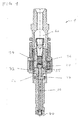
- the injector design as shown in Figure 1 uses the so-called free lift concept to improve the capability to activate at very high pressure.
- the free lift concept uses the momentum of an armature 32 to generate a hammering opening of a valve needle 20 (also referred to as kick effect) to overcome a hydraulic load on a seat especially at high pressures of e.g. 350 bar to 500 bar.
- the initial needle speed, based on this concept, is relatively high and this is very important for a fuel spray preparation at an initial opening transient of the valve 1.
- an electro-magnet 36 also referred to as a solenoid
- a magnetic force sustains the motion of the armature 32 and consequently the travelling of the needle 20 with an additional acceleration up to a kind of hard stop for stroke.
- the presence of the hard stop at a stop face 55 that limits the armature 32 travelling creates a bounce that affects the linearity behavior of a Ti mapping (flow rate versus activation time Ti) as an s-shaped region occurs.
- the hard stop creates a hydraulic sticking force after a bounce between the armature 32 and the stop faces 55 of a pole piece 34 with an additional delay in a closing event with respect to an electrical switch-off signal.
- This behavior can change during the lifetime of the valve 1 because wearing of the surfaces involved in the hard stop concept, so that a significant deviation of the flow rate versus time, is expected.
- both armature 32 and pole faces 55 have to be chromed to increase the hardness and minimize the wearing.
- Actual actuators use standard magnetic stainless steels (e.g. 430SS, i.e. in particular stainless steel having the SAE grade 430) as magnetic materials with a relatively high eddy current effect because of a bulk electrical conductivity. For this reason it is not easy to accurately control the magnetic force versus the needle position by the electronics in real time and, as a consequence, the flow mass for very low quantities especially into the ballistic operating range.
- the multiple injection strategy suffers from the relatively long demagnetization transient time related to the presence of an eddy current, too. This can limit separation time among activations and, hence, also a number of multiple injections for each engine cycle.
- the armature 32 is located between a hydro disc 26 (also referred to as supporting part) and an upper guide 27 (also referred to as top part or armature retainer).
- the hydro disc 26 and the upper guide 27 are welded onto the needle 20 so all these bodies 20, 26, 27 can move together.
- the armature 32 has a free space between the hydro disc 26 and the upper guide 27 to generate the momentum and the kick effect on the needle 20 when the solenoid 36 is activated.
- the armature 32 starts to move from a lower position (in contact with the hydro disc 26) because of the presence of a permanent magnet 37 located at a bottom side of the armature 32. This permanent magnet 37 generates a continuous pulling force to maintain a stable position of the armature 32 without any solenoid activation.
- m A is the armature mass and v T@kick is its speed at the contact event.
- This momentum generates an initial speed to the needle 20 to overcome the pressure of the fuel and to improve a spray preparation at an initial opening transient.
- the injection valve of Figure 1 uses a common stainless steel as a core material in the electro-magnet 36. However, this does not support a fast demagnetization process and multiple injection applications are difficult to realize.
- the injector design of Figure 1 supports a final damping and, thus, a speed reduction of the armature 32 before the contact (hard stop) because of a squish effect between the flat surfaces of the pole piece 34 and the armature 32.
- this approach cannot guarantee a good stability over population because of the complexity involved in fixing the parallelism of the stop faces 55 to gain the best damping effect and a complete elimination of the armature bounce.
- Another problem of this approach is related to the sticking hydraulic effect in the closing behavior with a delay to close the valve 1 and, thus, an increase of the mass flow associated to a specific activation time.
- Other approaches provide special armature geometries with dynamic pressure drop fixtures to get the damping (holes, slots and so on); these fixtures increase the cost of the product.
- the present invention proposes to solve the above-mentioned problems in particular with the following design factors, that can be combined, see also Figure 5 :
- the injection valve 1 has a valve body 14 defining a cavity 18.
- a valve needle 20 is arranged in the cavity 18 extending along the longitudinal axis 60 from a needle ball at the fluid outlet portion 40 of the fluid injection valve 1 to an armature retainer 27 at an opposite longitudinal end.
- An armature 32 is shifted over the valve needle 20 so that it is movable along the longitudinal axis 60 with respect to the valve needle 20 between the armature retainer 27 and a supporting part 26.
- the armature 32 is also axially displaceable with respect to the valve body 14.
- the injection valve 1 has an electromagnetic actuator unit 30 which comprises the armature 32 and an acceleration device 15 comprising a coil 38, a core 39 and a pole piece 34.
- the pole piece 34 is comprised by the valve body 14 in the present embodiment. More specifically, it is inserted into the non-magnetic shell 33 of the valve body 14 and welded thereto in a fluid tight manner the so that it hydraulically separates the armature 32 from the coil 38 and the core 39, both of which are arranged adjacent to the pole piece 34 on a side of the pole piece 34 facing away from the armature 32 outside of and surrounding the valve body 14.
- a permanent magnet 37 is arranged in the cavity 18 on the side of the armature 32 facing away from the pole piece 34. Also the permanent magnet 37 may be laterally surrounded by the non-magnetic shell 33.
- the pole piece 34 has a non-magnetic inlay 51 laterally overlapping the coil 38. Radially inward and radially outward of the non-magnetic inlay 51, the pole piece 34 comprises a magnetic material such as ferritic steel and in particular overlaps the core 39 laterally. For example, opposite magnetic poles may be achievable radially inward and radially outward of the non-magnetic inlay 51, respectively, in this way.
- the coil 38 When the electromagnetic actuator unit 30 is energized, the coil 38 generates a magnetic field which is shaped by the core 39 and the pole piece 34 and attracts the armature 32 towards the pole piece 34, in particular towards a stop face 55 of the pole piece 34.
- the armature 32 By means of interaction via the armature retainer 727, the armature 32 is operable to take the valve needle 20 with it in direction towards the pole piece 34, which in the present embodiment is the opening direction 62 that is directed from the fuel outlet portion 40 towards a fuel inlet and of the injection valve 1 opposite of the fuel outlet portion 14 with respect to the longitudinal axis 60.
- the armature 32 Before coming into engagement with the armature retainer 27, the armature 32 travels - with respect to the valve body 14 and the valve needle 20 - for an idle stroke in the opening direction 62 from a position in which it abuts on the supporting part 26 towards which it is biased by means of the permanent magnet 37.
- the injection valve 1 has two springs, a calibration spring 31 and a further spring acting as deceleration device 35.
- the calibration spring 31 bears on the armature retainer 27 at one axial end whereas the second axial end of the calibration spring 31 bears on a spring seat which is fixed with respect to the valve body on the side of the valve needle 20 remote from the fuel outlet portion 40.
- the deceleration device 35 abuts a body rest 15 which is positionally fix to the valve body 14 on the side of the armature 32 remote from the armature retainer 27 and on a needle rest 25 which is fixed to the needle 20 on the side of the body rest 15 remote from the armature 32.
- the armature 32 is operable to move the valve needle 20 out of its closing position and in the opening direction 62 against the bias of the calibration spring 31 and of the deceleration device 35.
- the flow sensitivity curve of a multi-holes injector can be used to reduce or to eliminate the dependence of the flow with respect to the needle/ball stroke also without the presence of a hard stop.
- the needle lift depending to the injector application, can be chosen in the range of 90 ⁇ m to 100 ⁇ m or higher to minimize the sensitivity of the multi-holes flow rate with respect to the effective needle lift.
- F tot is the net force over the armature, supporting the needle position depending to the electrical current I hold , the pressure P of the fluid, and the calibration condition of the static two springs 31, 35 force, compare Figure 2 .
- a typical flow instantaneous flow rate curve and associated Ti-mapping in this condition can be represented with a lot of benefit in terms of linearity behaviors and Qd min control, see Figure 3 .
- OPP1 is the opening valve event
- OPP2 is the maximum needle stroke
- OPP3 is the starting point of the back motion
- OPP4 is the closing valve event.
- Somaloy is an SMC (soft magnetic composite) that can be used in dry conditions to avoid chemical attack of aggressive liquids
- the base powdered is pure iron with nano-coating obtained by oxidation that drastically increases the macro electrical resistivity with limitation of eddy current effect.
- the housing can be formed by pressing to get a three-dimensional body, in particular with a lubricant to minimize friction.
- a post-annealing at 500°C can normalize the three-dimensional magnetic properties and can minimize internal residual postpress stresses. Thus, very good magnetic properties with low demagnetization times can be achieved.
- a good phasing of a peak of a current during boost phase and the hammering effect of the armature 32 to open the valve 1 at maximum speed of the armature 32 for better spray preparation can be achieved, see Figure 4A .
- An initial distance between the armature 32 and the stop face 55 of the pole piece 34, including the free lift, can be set for example at 200 ⁇ m +/- 100 ⁇ m or +/-50 ⁇ m.
- the free lift can be set, for example, at 50 ⁇ m +/- 25 ⁇ m or +/- 10 ⁇ m.
- the permanent magnet 37 can be used to support the initial armature position (static magnetic force on the armature 32). After the armature- needle contact event, the electrical current can be freewheeled to hold a level to balance the net force over the armature 32.
- the valve spring 35 increases its contrast with the maximum value at the final armature position that can be designed into the non-sensitive area of the flow curve with respect to the needle position, see Figure 4B .
- a calibration spring 31 can be used to minimize the piece-to-piece flow variation in the population as a normal way to calibrate the solenoid injector.
- the design avoids any contact between the pole piece 34 and the armature 32, also at fully opened valve 1.
- the armature 32 is spaced apart from the stop face 55 throughout the operation of the injection valve.
- this injection valve 1 is improved also because all magnetic forces (in particular from the coil 38 and from the permanent 37 magnet) can act on the armature 32 only in an axial direction along an axis 60 without radial effect because the external shell 33 is made from a non-magnetic material like stainless steel 316SS, i.e. in particular stainless steel having the SAE steel grade 316. So a reduced friction on the moving parts is also achieved.
- the combination of the above-mentioned design parameters can improve the performances of the multi-streaming (multi-holes) injector 1 of Figure 2 with benefits in terms of Qd min reduction, spray formation at opening transient, linearity behaviors and degradation over a lifetime for high pressure direct injector applications.
- an actuator for a multi-holes inward opening application of the present invention is able to control a flow without a traditional hard stop with chrome plating for high pressure injector application (i.e. at 350 to 500 bar) with reduced degradation performances over the product lifetime.
- An actuator to control the flow rate is realized in particular with the combination of a high performance magnetic material (i.e. from the Somaloy family) with a U-shape design and a double spring system with one spring (i.e. the spring of the deceleration device 35) with a high stiffness of preferably > 100 N/mm) used to stop the motion at final stroke.
- a high performance magnetic material i.e. from the Somaloy family
- a double spring system with one spring i.e. the spring of the deceleration device 35
- a high stiffness of preferably > 100 N/mm used to stop the motion at final stroke.
- the U-shaped housing design in combination with the external non-magnetic shell 33 can avoid radial magnetic forces, preferably in combination with a permanent magnet 37 to act in axial direction on the armature 32.
- the combination of the previous design parameters can support the catalyst heating strategy, too.
- the combination of the previous design parameters can serve for both stratified and homogenous multiple injections strategy.
- the invention is not restricted to the exemplary embodiments by the description on the basis of said exemplary embodiments. Rather, the invention encompasses any new feature and also any combination of features which, in particular, comprises any combination of features in the patent claims and any combination of features in the exemplary embodiments, even if this feature or this combination itself is not explicitly specified in the patent claims or exemplary embodiments.
Abstract
- a valve body (14) comprising a cavity (18) and a fluid outlet portion (40),
- a valve needle (20) axially movable in the cavity (18), the valve needle (20) preventing a fluid flow through the fluid outlet portion (40) in a closing position and displaceable in an opening direction (62) along a longitudinal axis (60) to other positions for releasing the fluid flow through the fluid outlet portion (40),
- an electro-magnetic actuator unit (30) being configured to actuate the valve needle (20),
wherein the actuator unit (30) comprises
- an armature (32) which is arranged in the cavity (18) and being axially moveable relative to the valve needle (20), the armature (32) being operable to move the valve needle (20),
- an acceleration device (50) comprising a pole piece (34) which is arranged in the cavity (18) subsequent to the armature (32) in the opening direction (62), the acceleration device (50) being fixed to the cavity (18) and being operable to move the armature (32) by applying a magnetic force,
- a deceleration device (35) being arranged in the cavity (18), the deceleration device (35) being configured to dampen or to avoid an impact of the armature (32) onto the pole piece (34).
Description
- The invention relates to an injection valve.
- An object of the invention is to create an injection valve which facilitates a reliable and precise functioning of the injection valve.
- This object is achieved inter alia by the features of the independent claim. Advantageous embodiments of the invention are given in the dependent claims.
- According to at least one embodiment, the injection valve comprises a valve body. The valve body is preferably the mechanically stabilizing part of the injection valve. The valve body comprises a cavity and a fluid outlet portion. In particular, the valve body hydraulically couples a fluid inlet portion to the fluid outlet portion via the cavity.
- According to at least one embodiment, the injection valve comprises a valve needle. The valve needle is axially movable in the cavity. In a closing position, the valve needle prevents a fluid flow through the fluid outlet portion. In other positions, the valve needle allows the release of the fluid flow through the fluid outlet portion. The valve needle is in particular displaceable in an opening direction along a longitudinal axis to the other positions for releasing the fluid flow through the fluid outlet portion.
- According to at least one embodiment, the injection valve comprises an electro-magnetic actuator unit being configured to actuate the valve needle. Preferably, by means of the actuator unit the valve needle can be moved reversibly, i.e. in reciprocating fashion.
- The injection valve may be an inward opening injection valve in one embodiment. In this case, the opening direction is in particular directed from the fluid outlet portion towards the fluid inlet portion, i.e. against the direction of the fluid flow. In an alternative embodiment, the injection valve is an outward opening injection valve. In this case, the opening direction is in particular directed from the fluid inlet portion towards the fluid outlet portion, i.e. in the same direction as the direction of the fluid flow.
- According to at least one embodiment, the actuator unit comprises an armature which is arranged in the cavity. The armature is axially moveable relative to the valve body and also relative to the valve needle. The armature is designed to move the valve needle. The armature is at least temporarily in direct contact with the valve needle. The valve needle in particular has a top part which may also be denoted as an armature retainer. The armature is preferably operable to engage the top part for moving the valve needle. In particular, the armature is formed like a disk with a central hole, the valve needle being fed through said hole. The armature retainer may expediently overlap with the armature in top view along the longitudinal axis.
- According to at least one embodiment, the actuator unit comprises an acceleration device. The acceleration device may comprise a pole piece. The pole piece is preferably arranged in the cavity subsequent to the armature in the opening direction. For example and in particular in case of an inward opening valve, the acceleration device, in particular at least its pole piece, may be arranged in the cavity on a side of the armature remote from the fluid outlet portion. Preferably, the acceleration device is fixed to the valve body so that there is no relative movement between the valve body and the acceleration device. The acceleration device can be free of moving parts. By way of example, the acceleration device comprises or is composed of an electro-magnet. The acceleration device is operable to move the armature by applying a magnetic force to the armature.
- That the pole piece is arranged in the cavity also encompasses a configuration in which the pole piece is comprised by the valve body and contributes to hydraulically sealing the cavity of the valve body against the surrounding of the injection valve or against other components of the injection valve. In this case, the pole piece is in particular inserted into another part of the valve body. In any case, the acceleration device preferably has at least one surface which faces towards the armature and towards which the armature is attracted when the electromagnetic-actuator unit is energized. This surface is briefly denoted as stop face in the following. The stop face may expediently be arranged in the cavity or constitute a surface region of the cavity.
- According to at least one embodiment, the actuator unit comprises a deceleration device which is preferably arranged in the cavity. The deceleration device is configured to dampen or to avoid an impact of the armature onto the acceleration device, in particular onto the pole piece, for example onto the stop face. In other words, the deceleration device is designed to prevent a so-called hard stop of the armature. According to at least one embodiment, the deceleration device comprises a spring. The spring may be located on a side of the armature remote from the pole piece. For example and in particular in case of an inward opening injection valve, the spring is preferably located between the armature and the fluid outlet portion. By way of example, the spring has a spring constant of at least 50 N/mm or 100 N/mm and/or at most 200 N/mm or 400 N/mm.
- According to at least one embodiment, the spring is fixed between a body rest and a needle rest. In this case, the body rest is a part of the valve body which is located between the armature and the spring. In particular, the body rest completely surrounds the spring. The needle rest is fixed onto the needle or is a part of the needle. The needle rest may be fixed on a side of the spring remote from the body rest. For example and in particular in case of an inward opening injection valve, the needle rest is preferably located between the spring and the fluid outlet portion.
- According to at least one embodiment, in the closing position the spring of the deceleration device has a pre-stressing of at least 7.5 N or 10 N and/or of at most 20 N or 15 N. The pre-stressing can be tensile or compressive. The injection valve has, in one embodiment, an additional calibration spring for forcing biasing the valve needle towards the closing position and to retain the valve needle in the closing position when the actuator unit is de-energized.
- According to at least one embodiment, a speed of the armature at the acceleration device - in particular at that longitudinal position where the armature comes into contact with the stop face - is reduced to at most 50% or preferably to at most 20% or more preferably to at most 10% of a maximum speed of the armature by means of the deceleration device. In a preferred embodiment however, the deceleration device is designed to prevent a direct contact between the armature and the acceleration device in the intended use of the injection valve. In particular the deceleration device is operable to prevent a direct contact between the armature and the pole piece throughout the operation of the injection valve. In other words, the injection valve is configured in such fashion by means of the deceleration device that the armature remains spaced apart from the stop face in a fully open configuration of the injection valve.
- According to at least one embodiment, the actuator unit comprises at least one permanent magnet which is preferably arranged between the armature and the deceleration device in an axial direction along the valve needle. The permanent magnet is in particular operable to bias the armature in a direction away from the armature retainer of the valve needle. In this way, the permanent magnet may advantageously contribute to set a predefined idle stroke of the armature before engaging with the armature retainer for moving the valve needle away from the closing position.
- According to at least one embodiment, the armature is or comprises a permanent magnet. In one development, the acceleration actuator unit comprises the permanent magnet and the armature is or comprises a further permanent magnet.
- According to at least one embodiment, the acceleration device comprises at least one electro-magnet with a coil and a core. The coil and the core may be arranged on a side of the pole piece remote from the armature, wherein the pole piece may be an individual part adjacent to the core and in particular adjoining the core or the pole piece may be an axial end portion of the core which is in one piece with the core. For example and in particular in the case of an inward opening valve, the coil and the core are preferably arranged on a side of the armature remote from the fluid outlet. Moreover, the coil and/or the core are preferably formed symmetric to an axis along which the valve needle can be moved.
- According to at least one embodiment, the core comprises or consists of at least one soft magnetic composite. The soft magnetic composite is preferably composed of metal powder particles with an electrically isolating surface.
- According to at least one embodiment, the core is of a U-shape or of a double U-shape when seen in a cross-sectional view. The legs of the at least one U are preferably oriented parallel with the valve needle and in particular the longitudinal axis. An open end of the U can face the armature. In this way, each of the legs may, for example, correspond to one magnetic pole so that a particular efficient force transfer to the armature is achievable.
- According to at least one embodiment, the valve body comprises a non-magnetic shell which is arranged around the armature when seen in a radial direction. In other words, the non-magnetic shell extends circumferentially around the armature. In this way, parasitic magnetic flux may be particularly small.
- According to at least one embodiment, in the closing position the armature rests on a supporting part of the valve needle. The supporting part is preferably located on a side of the armature facing away from the pole piece. For example and in particular in case of an inward opening injection valve, the supporting part is located on a side of the armature facing the fluid outlet portion. In the closing position, the armature is preferably distant from a top part of the valve needle. The armature is in particular operable to engage the top part in order to move the valve needle in the opening direction for opening the injection valve. For example and in particular in case of an inward opening injection valve, the top part is on a side of the armature remote from the fluid outlet portion.
- According to at least one embodiment, the acceleration device is designed to accelerate the armature from the supporting part to the top part in order to move the valve needle and in order to open the injection valve.
- According to at least one embodiment, the injection valve is designed for high-pressure applications with a fluid pressure between 350 bar and 500 bar, inclusive.
- According to at least one embodiment, the acceleration device and/or the armature is/are free of a chrome plating.
- Exemplary embodiments of the invention are explained in the following with the aid of schematic drawings. Elements of the same design and function that appear in different illustrations are identified by the same reference character.
- In the Figures:
- Figure 1
- shows a sectional view of an injection valve according to the prior art,
- Figure 2
- shows a flow sensitivity curve of an injection valve according to the invention,
- Figure 3
- shows a flow rate curve and an associated Timapping of an injection valve according to the invention,
- Figure 4
- shows a dependency of a current versus the time and a lift sensitivity curve of an injection valve according to the invention, and
- Figure 5
- shows a sectional view of an injection valve according to the invention.
- Currently, the injector design as shown in
Figure 1 uses the so-called free lift concept to improve the capability to activate at very high pressure. The free lift concept uses the momentum of anarmature 32 to generate a hammering opening of a valve needle 20 (also referred to as kick effect) to overcome a hydraulic load on a seat especially at high pressures of e.g. 350 bar to 500 bar. The initial needle speed, based on this concept, is relatively high and this is very important for a fuel spray preparation at an initial opening transient of thevalve 1. - Due the fact that an electro-
magnet 36, also referred to as a solenoid, is active during the opening transient after the armature needle kick event, a magnetic force sustains the motion of thearmature 32 and consequently the travelling of theneedle 20 with an additional acceleration up to a kind of hard stop for stroke. The presence of the hard stop at astop face 55 that limits thearmature 32 travelling (the so-called lift) creates a bounce that affects the linearity behavior of a Ti mapping (flow rate versus activation time Ti) as an s-shaped region occurs. - However, due to increasingly stringent requirements the solenoid injector must be controllable with or without the mechatronic approach in order to deliver very small fuel quantities.
- In addition, the hard stop creates a hydraulic sticking force after a bounce between the
armature 32 and the stop faces 55 of apole piece 34 with an additional delay in a closing event with respect to an electrical switch-off signal. This behavior can change during the lifetime of thevalve 1 because wearing of the surfaces involved in the hard stop concept, so that a significant deviation of the flow rate versus time, is expected. - To get a traditional hard stop in that design, both
armature 32 and pole faces 55 have to be chromed to increase the hardness and minimize the wearing. Actual actuators use standard magnetic stainless steels (e.g. 430SS, i.e. in particular stainless steel having the SAE grade 430) as magnetic materials with a relatively high eddy current effect because of a bulk electrical conductivity. For this reason it is not easy to accurately control the magnetic force versus the needle position by the electronics in real time and, as a consequence, the flow mass for very low quantities especially into the ballistic operating range. - Thus, the multiple injection strategy suffers from the relatively long demagnetization transient time related to the presence of an eddy current, too. This can limit separation time among activations and, hence, also a number of multiple injections for each engine cycle.
- In the design in
Figure 1 , thearmature 32 is located between a hydro disc 26 (also referred to as supporting part) and an upper guide 27 (also referred to as top part or armature retainer). Thehydro disc 26 and theupper guide 27 are welded onto theneedle 20 so all thesebodies armature 32 has a free space between thehydro disc 26 and theupper guide 27 to generate the momentum and the kick effect on theneedle 20 when thesolenoid 36 is activated. Thearmature 32 starts to move from a lower position (in contact with the hydro disc 26) because of the presence of apermanent magnet 37 located at a bottom side of thearmature 32. Thispermanent magnet 37 generates a continuous pulling force to maintain a stable position of thearmature 32 without any solenoid activation. - The armature's overall force Ftot(t) into the free lift space in dependence on the time t provides the momentum to support the hammering effect applying a solenoid current as the following dynamic equation:

- Here, mA is the armature mass and vT@kick is its speed at the contact event. This momentum generates an initial speed to the
needle 20 to overcome the pressure of the fuel and to improve a spray preparation at an initial opening transient. For example, the injection valve ofFigure 1 uses a common stainless steel as a core material in the electro-magnet 36. However, this does not support a fast demagnetization process and multiple injection applications are difficult to realize. - The injector design of
Figure 1 supports a final damping and, thus, a speed reduction of thearmature 32 before the contact (hard stop) because of a squish effect between the flat surfaces of thepole piece 34 and thearmature 32. The larger the surfaces, the higher the damping effect, in particular in the last 5 to 10 µm before contact. However, this approach cannot guarantee a good stability over population because of the complexity involved in fixing the parallelism of the stop faces 55 to gain the best damping effect and a complete elimination of the armature bounce. Another problem of this approach is related to the sticking hydraulic effect in the closing behavior with a delay to close thevalve 1 and, thus, an increase of the mass flow associated to a specific activation time. Other approaches provide special armature geometries with dynamic pressure drop fixtures to get the damping (holes, slots and so on); these fixtures increase the cost of the product. - The present invention proposes to solve the above-mentioned problems in particular with the following design factors, that can be combined, see also
Figure 5 : - using an improved flow sensitivity curve of a generic multi-holes inward injector,
- using a core material for the electro-
magnet 30 with an improved magnetic characteristic, - using a
deceleration device 35, e. g. in the form of a secondary spring with high stiffness, in order to eliminate the hard stop concept, - using a
permanent magnet 37 to support the free lift concept, and/or - using a
non-magnetic shell 33 around thearmature 32 to support the injector mechanical structural resistance at high pressures. - More specifically, the
injection valve 1 has avalve body 14 defining acavity 18. Avalve needle 20 is arranged in thecavity 18 extending along thelongitudinal axis 60 from a needle ball at thefluid outlet portion 40 of thefluid injection valve 1 to anarmature retainer 27 at an opposite longitudinal end. Anarmature 32 is shifted over thevalve needle 20 so that it is movable along thelongitudinal axis 60 with respect to thevalve needle 20 between thearmature retainer 27 and a supportingpart 26. Expediently, thearmature 32 is also axially displaceable with respect to thevalve body 14. - The
injection valve 1 has anelectromagnetic actuator unit 30 which comprises thearmature 32 and anacceleration device 15 comprising a coil 38, a core 39 and apole piece 34. Thepole piece 34 is comprised by thevalve body 14 in the present embodiment. More specifically, it is inserted into thenon-magnetic shell 33 of thevalve body 14 and welded thereto in a fluid tight manner the so that it hydraulically separates thearmature 32 from the coil 38 and the core 39, both of which are arranged adjacent to thepole piece 34 on a side of thepole piece 34 facing away from thearmature 32 outside of and surrounding thevalve body 14. - A
permanent magnet 37 is arranged in thecavity 18 on the side of thearmature 32 facing away from thepole piece 34. Also thepermanent magnet 37 may be laterally surrounded by thenon-magnetic shell 33. - The
pole piece 34 has anon-magnetic inlay 51 laterally overlapping the coil 38. Radially inward and radially outward of thenon-magnetic inlay 51, thepole piece 34 comprises a magnetic material such as ferritic steel and in particular overlaps the core 39 laterally. For example, opposite magnetic poles may be achievable radially inward and radially outward of thenon-magnetic inlay 51, respectively, in this way. - When the
electromagnetic actuator unit 30 is energized, the coil 38 generates a magnetic field which is shaped by the core 39 and thepole piece 34 and attracts thearmature 32 towards thepole piece 34, in particular towards astop face 55 of thepole piece 34. By means of interaction via the armature retainer 727, thearmature 32 is operable to take thevalve needle 20 with it in direction towards thepole piece 34, which in the present embodiment is the openingdirection 62 that is directed from thefuel outlet portion 40 towards a fuel inlet and of theinjection valve 1 opposite of thefuel outlet portion 14 with respect to thelongitudinal axis 60. Before coming into engagement with thearmature retainer 27, thearmature 32 travels - with respect to thevalve body 14 and the valve needle 20 - for an idle stroke in theopening direction 62 from a position in which it abuts on the supportingpart 26 towards which it is biased by means of thepermanent magnet 37. - The
injection valve 1 according to the present embodiment has two springs, a calibration spring 31 and a further spring acting asdeceleration device 35. The calibration spring 31 bears on thearmature retainer 27 at one axial end whereas the second axial end of the calibration spring 31 bears on a spring seat which is fixed with respect to the valve body on the side of thevalve needle 20 remote from thefuel outlet portion 40. Thedeceleration device 35 abuts abody rest 15 which is positionally fix to thevalve body 14 on the side of thearmature 32 remote from thearmature retainer 27 and on aneedle rest 25 which is fixed to theneedle 20 on the side of thebody rest 15 remote from thearmature 32. Thearmature 32 is operable to move thevalve needle 20 out of its closing position and in theopening direction 62 against the bias of the calibration spring 31 and of thedeceleration device 35. - The flow sensitivity curve of a multi-holes injector (see
Figure 2 ) can be used to reduce or to eliminate the dependence of the flow with respect to the needle/ball stroke also without the presence of a hard stop. The needle lift, depending to the injector application, can be chosen in the range of 90 µm to 100 µm or higher to minimize the sensitivity of the multi-holes flow rate with respect to the effective needle lift. - Using the free lift concept and the hammering effect to support the high pressure opening capability in combination with the
deceleration device 35 consisting of a spring with a high stiffness i.e. between 100 N/mm and 200 N/mm, it is possible to guarantee the best time evolution of the instantaneous flow rate and the Ti-mapping without the S-shape formation. A gradient of that curve also into the ballistic area can be smoothed for better electronic control. Final needle stroke (and related flow rate across the multi-holes) is determined, due to the Hooke law, by the following equation:
- In this equation, Ftot is the net force over the armature, supporting the needle position depending to the electrical current Ihold, the pressure P of the fluid, and the calibration condition of the static two
springs 31, 35 force, compareFigure 2 . A typical flow instantaneous flow rate curve and associated Ti-mapping in this condition can be represented with a lot of benefit in terms of linearity behaviors and Qdmin control, seeFigure 3 . - In the schematic representation of
Figure 3 , left side, OPP1 is the opening valve event, OPP2 is the maximum needle stroke, OPP3 is the starting point of the back motion, and OPP4 is the closing valve event. - For the core 39 of the electro-
magnet 30 of the acceleration device 50, so-called Somaloy is preferably used. Somaloy is an SMC (soft magnetic composite) that can be used in dry conditions to avoid chemical attack of aggressive liquids, the base powdered is pure iron with nano-coating obtained by oxidation that drastically increases the macro electrical resistivity with limitation of eddy current effect. The housing can be formed by pressing to get a three-dimensional body, in particular with a lubricant to minimize friction. A post-annealing at 500°C can normalize the three-dimensional magnetic properties and can minimize internal residual postpress stresses. Thus, very good magnetic properties with low demagnetization times can be achieved. - By the use of these Somaloy materials in particular in combination with a U-shaped core 39 (when seen in a cross-sectional view, see
Figure 5 ), a good phasing of a peak of a current during boost phase and the hammering effect of thearmature 32 to open thevalve 1 at maximum speed of thearmature 32 for better spray preparation can be achieved, seeFigure 4A . An initial distance between thearmature 32 and thestop face 55 of thepole piece 34, including the free lift, can be set for example at 200 µm +/- 100 µm or +/-50 µm. - The free lift can be set, for example, at 50 µm +/- 25 µm or +/- 10 µm. The
permanent magnet 37 can be used to support the initial armature position (static magnetic force on the armature 32). After the armature- needle contact event, the electrical current can be freewheeled to hold a level to balance the net force over thearmature 32. Thevalve spring 35 increases its contrast with the maximum value at the final armature position that can be designed into the non-sensitive area of the flow curve with respect to the needle position, seeFigure 4B . In this way, the flow rate after the opening transient can be stabilized for the rest of the activation time with a minimum sensitivity with respect to the current profile level, magnetic path and valve spring tolerances, for example if the needle stroke is in the range of 100 µm in accordance withFigure 4B . A calibration spring 31 can be used to minimize the piece-to-piece flow variation in the population as a normal way to calibrate the solenoid injector. - The elimination of the hard stop in this design, preferably in combination with the Somaloy material in the electro-
magnet 30, provides a fast closing because there is no sticking between thearmature 32 and thepole piece 34. Preferably, the design avoids any contact between thepole piece 34 and thearmature 32, also at fully openedvalve 1. In particular, thearmature 32 is spaced apart from thestop face 55 throughout the operation of the injection valve. A fast demagnetization process for better supporting the multiple injection capability and the reliability of the product over its lifetime, because of the elimination of wear between thearmature 32 and thepole piece 51 due to the contact degradation (that is present also with chrome layer deposition over the pole faces), can be achieved. - The lifetime of this
injection valve 1 is improved also because all magnetic forces (in particular from the coil 38 and from the permanent 37 magnet) can act on thearmature 32 only in an axial direction along anaxis 60 without radial effect because theexternal shell 33 is made from a non-magnetic material like stainless steel 316SS, i.e. in particular stainless steel having the SAE steel grade 316. So a reduced friction on the moving parts is also achieved. - In this design with the proposed Somaloy U-shaped core 39 in combination with the free lift concept supported by the
permanent magnet 37, a relatively high pulling force (i.e. 5 N to 7 N), to maintain a stable original position of thearmature 32 without solenoid activation and better support of the repeatability of the actuations under work conditions, can be realized. This relatively high force, derived from thepermanent magnet 37, also improves the "no bounce" at closing event OPP4. The elimination of the hard stop concept and associated chrome plating also reduces environmental pollution. - Thus, the combination of the above-mentioned design parameters can improve the performances of the multi-streaming (multi-holes)
injector 1 ofFigure 2 with benefits in terms of Qdmin reduction, spray formation at opening transient, linearity behaviors and degradation over a lifetime for high pressure direct injector applications. - Hence, an actuator for a multi-holes inward opening application of the present invention is able to control a flow without a traditional hard stop with chrome plating for high pressure injector application (i.e. at 350 to 500 bar) with reduced degradation performances over the product lifetime.
- An actuator to control the flow rate is realized in particular with the combination of a high performance magnetic material (i.e. from the Somaloy family) with a U-shape design and a double spring system with one spring (i.e. the spring of the deceleration device 35) with a high stiffness of preferably > 100 N/mm) used to stop the motion at final stroke. The flow sensitivity characteristic curve of the multi-holes benefits from the dismissal of the hard stop concept for high pressure applications.
- The combination of the free lift concept realized with the support of a
permanent magnet 37 and the high spring stiffness to support the instantaneous flow rate shape to avoid the Ti-mapping S-shape, achieves good spray behaviors at the opening phase and better supports the Qdmin capability for high pressure application (i.e. 350 bar to 500 bar). The U-shaped housing design in combination with the externalnon-magnetic shell 33 can avoid radial magnetic forces, preferably in combination with apermanent magnet 37 to act in axial direction on thearmature 32. - The combination of the previous design parameters can support the catalyst heating strategy, too. The combination of the previous design parameters can serve for both stratified and homogenous multiple injections strategy.
- These design aspects can be used for direct multi-streaming injector applications with a solenoid actuator at pressures of less than 350 bar, too, as well as for low pressure indirect injector applications.
- The invention is not restricted to the exemplary embodiments by the description on the basis of said exemplary embodiments. Rather, the invention encompasses any new feature and also any combination of features which, in particular, comprises any combination of features in the patent claims and any combination of features in the exemplary embodiments, even if this feature or this combination itself is not explicitly specified in the patent claims or exemplary embodiments.
Claims (15)
- Injection valve (1) for an automotive engine comprising:- a valve body (14) comprising a cavity (18) and a fluid outlet portion (40),- a valve needle (20) axially movable in the cavity (18), the valve needle (20) preventing a fluid flow through the fluid outlet portion (40) in a closing position and displaceable in an opening direction (62) along a longitudinal axis (60) to other positions for releasing the fluid flow through the fluid outlet portion (40),- an electro-magnetic actuator unit (30) being configured to actuate the valve needle (20),wherein the actuator unit (30) comprises- an armature (32) which is arranged in the cavity (18) and being axially moveable relative to the valve needle (20), the armature (32) being operable to move the valve needle (20),- an acceleration device (50) comprising a pole piece (34) which is arranged in the cavity (18) subsequent to the armature (32) in the opening direction (62), the acceleration device (50) being fixed to the cavity (18) and being operable to move the armature (32) by applying a magnetic force,- a deceleration device (35) being arranged in the cavity (18), the deceleration device (35) being configured to dampen or to avoid an impact of the armature (32) onto the pole piece (34).
- Injection valve (1) according to the preceding claim, wherein the deceleration device (35) comprises a spring located on a side of the armature (32) remote from the pole piece (34), the spring having a spring constant between 100 N/mm and 400 N/mm, and
wherein the spring is fixed between a body rest (15) and a needle rest (25),
the body rest (15) being a part of the valve body (14) located between the armature (32) and the spring, and the needle rest (25) being fixed onto the needle (20) on a side of the spring remote from the body rest (15). - Injection valve (1) according to the preceding claim,
wherein the spring is located between the armature (32) and the fluid outlet portion (40) and the needle rest (25) is fixed onto the needle between the spring and the fluid outlet portion (40). - Injection valve (1) according to claim 2 or 3,
wherein in the closing position the spring of the deceleration device (35) has a pre-stressing of between 7.5 N and 20 N, inclusive. - Injection valve (1) according to any one of the preceding claims,
wherein the deceleration device (35) is operable to prevent a direct contact between the armature and the pole piece (34) in the intended use of the injection valve (1). - Injection valve (1) according to any one of the preceding claims,
wherein the actuator unit (30) comprises at least one permanent magnet (37) which is arranged between the armature (32) and the deceleration device (35) in an axial direction along the valve needle (20). - Injection valve (1) according to the preceding claim,
wherein the armature (32) is or comprises a permanent magnet. - Injection valve (1) according to any one of the preceding claims,
wherein the acceleration device (50) comprises at least one electro-magnet (36) with a coil (38) and a core (39), wherein the coil (38) and the core (39) are arranged on a side of the pole piece (32) remote from the armature (30). - Injection valve (1) according to the preceding claim,
wherein the core (39) comprises or consists of a soft magnetic composite which is composed of metal powder particles with an electrically isolating surface. - Injection valve (1) according to claim 8 or 9, wherein the coil (38) and the core (39) are formed symmetrically with regard to the longitudinal axis (60) along which the valve needle (20) can be moved.
- Injection valve (1) according to the preceding claim,
wherein the core (39) is of a U-shape or of a double U-shape when seen in a cross-sectional view. - Injection valve (1) according to any one of the preceding claims,
wherein the valve body (14) comprises a non-magnetic shell (33) which is arranged around the armature (32) when seen in a radial direction. - Injection valve (1) according to any one of the preceding claims,
wherein, in the closing position, the armature (32) rests on a supporting part (26) of the valve needle (20), the supporting part (26) is located on a side of the armature (32) facing away from the pole piece (34),
wherein in the closing position the armature (32) is distant from a top part (27) of the valve needle (20),
wherein the acceleration device (50) is designed to accelerate the armature (32) from the supporting part (26) to the top part (27) and
wherein the armature (32) is operable to engage the top part (27) in order to move the valve needle (20) in the opening direction (62) for opening the injection valve (1). - Injection valve (1) according to any one of the preceding claims,
wherein the injection valve (1) is designed for high-pressure application with a fluid pressure between 350 bar and 500 bar, - Injection valve (1) according to any one of the preceding claims,
wherein the acceleration device (50) and/or the armature (32) is free of a chrome plating.
Priority Applications (1)
| Application Number | Priority Date | Filing Date | Title |
|---|---|---|---|
| EP13188648.3A EP2863042B1 (en) | 2013-10-15 | 2013-10-15 | Injection valve |
Applications Claiming Priority (1)
| Application Number | Priority Date | Filing Date | Title |
|---|---|---|---|
| EP13188648.3A EP2863042B1 (en) | 2013-10-15 | 2013-10-15 | Injection valve |
Publications (2)
| Publication Number | Publication Date |
|---|---|
| EP2863042A1 true EP2863042A1 (en) | 2015-04-22 |
| EP2863042B1 EP2863042B1 (en) | 2016-06-22 |
Family
ID=49354554
Family Applications (1)
| Application Number | Title | Priority Date | Filing Date |
|---|---|---|---|
| EP13188648.3A Active EP2863042B1 (en) | 2013-10-15 | 2013-10-15 | Injection valve |
Country Status (1)
| Country | Link |
|---|---|
| EP (1) | EP2863042B1 (en) |
Cited By (3)
| Publication number | Priority date | Publication date | Assignee | Title |
|---|---|---|---|---|
| WO2016058773A1 (en) * | 2014-10-15 | 2016-04-21 | Continental Automotive Gmbh | Fuel injection valve |
| EP3361085A1 (en) * | 2017-02-14 | 2018-08-15 | Continental Automotive GmbH | Electromagnetic switching valve and high-pressure fuel pump |
| CN114458506A (en) * | 2022-03-09 | 2022-05-10 | 哈尔滨工程大学 | Electromagnetic-permanent magnet multi-magnetic field combined high-speed electromagnetic valve with gradually increased buffering |
Citations (6)
| Publication number | Priority date | Publication date | Assignee | Title |
|---|---|---|---|---|
| DE19946602A1 (en) * | 1999-09-29 | 2001-04-12 | Bosch Gmbh Robert | Fuel injector |
| US20100236526A1 (en) * | 2009-03-20 | 2010-09-23 | Tianjin University | Common rail electronic control injector |
| DE102009045174A1 (en) * | 2009-09-30 | 2011-04-07 | Robert Bosch Gmbh | Magnetic stack for highly dynamic valves |
| DE102010064273A1 (en) * | 2010-12-28 | 2012-06-28 | Robert Bosch Gmbh | Fuel injection valve for fuel injection systems of internal combustion engines, has restoring spring provided at outer circumference of valve needle, where valve needle is provided with movable armature for actuating valve closing body |
| EP2628941A1 (en) * | 2012-02-15 | 2013-08-21 | Robert Bosch Gmbh | Fuel injection valve |
| EP2634412A1 (en) * | 2012-02-29 | 2013-09-04 | Robert Bosch Gmbh | Injection valve |
-
2013
- 2013-10-15 EP EP13188648.3A patent/EP2863042B1/en active Active
Patent Citations (6)
| Publication number | Priority date | Publication date | Assignee | Title |
|---|---|---|---|---|
| DE19946602A1 (en) * | 1999-09-29 | 2001-04-12 | Bosch Gmbh Robert | Fuel injector |
| US20100236526A1 (en) * | 2009-03-20 | 2010-09-23 | Tianjin University | Common rail electronic control injector |
| DE102009045174A1 (en) * | 2009-09-30 | 2011-04-07 | Robert Bosch Gmbh | Magnetic stack for highly dynamic valves |
| DE102010064273A1 (en) * | 2010-12-28 | 2012-06-28 | Robert Bosch Gmbh | Fuel injection valve for fuel injection systems of internal combustion engines, has restoring spring provided at outer circumference of valve needle, where valve needle is provided with movable armature for actuating valve closing body |
| EP2628941A1 (en) * | 2012-02-15 | 2013-08-21 | Robert Bosch Gmbh | Fuel injection valve |
| EP2634412A1 (en) * | 2012-02-29 | 2013-09-04 | Robert Bosch Gmbh | Injection valve |
Cited By (5)
| Publication number | Priority date | Publication date | Assignee | Title |
|---|---|---|---|---|
| WO2016058773A1 (en) * | 2014-10-15 | 2016-04-21 | Continental Automotive Gmbh | Fuel injection valve |
| US10711749B2 (en) | 2014-10-15 | 2020-07-14 | Vitesco Technologies GmbH | Fuel injection valve |
| EP3361085A1 (en) * | 2017-02-14 | 2018-08-15 | Continental Automotive GmbH | Electromagnetic switching valve and high-pressure fuel pump |
| CN114458506A (en) * | 2022-03-09 | 2022-05-10 | 哈尔滨工程大学 | Electromagnetic-permanent magnet multi-magnetic field combined high-speed electromagnetic valve with gradually increased buffering |
| CN114458506B (en) * | 2022-03-09 | 2022-12-09 | 哈尔滨工程大学 | Electromagnetic-permanent magnet multi-magnetic field combined high-speed electromagnetic valve with gradually increased buffering |
Also Published As
| Publication number | Publication date |
|---|---|
| EP2863042B1 (en) | 2016-06-22 |
Similar Documents
| Publication | Publication Date | Title |
|---|---|---|
| US8684285B2 (en) | Fuel injection valve | |
| EP2918816B1 (en) | Fuel injector | |
| EP1878908B1 (en) | Electromagnetic fuel injection valve | |
| JP6087210B2 (en) | Fuel injection valve | |
| US9528482B2 (en) | Electromagnetic fuel injection valve | |
| US9382885B2 (en) | Fuel injection valve for an internal combustion engine | |
| US7946276B2 (en) | Protection device for a solenoid operated valve assembly | |
| EP2863042B1 (en) | Injection valve | |
| EP2851551B1 (en) | Fluid injection valve | |
| EP3034853B1 (en) | Coil assembly and fluid injection valve | |
| CN107923354B (en) | Valve for metering a fluid | |
| KR101970081B1 (en) | Fuel injection valve | |
| WO2018115197A1 (en) | Valve assembly for an injection valve and injection valve | |
| KR102139895B1 (en) | Injection valve with magnetic ring element | |
| US20180195477A1 (en) | Valve for metering a fluid | |
| EP2065591A1 (en) | Fuel injector with mechanic damping | |
| EP3504421A1 (en) | Valve assembly for an injection valve and injection valve | |
| JP5786819B2 (en) | solenoid valve | |
| JP2023531083A (en) | solenoid valve | |
| JP2023531082A (en) | solenoid valve | |
| EP2980395A1 (en) | Fuel injection valve for an internal combustion engine | |
| JP2006307647A (en) | Solenoid fuel injection valve | |
| US20130240642A1 (en) | Magnetic actuator, valve as well as use of a material in magnetic actuators | |
| WO2019073816A1 (en) | Fuel injection valve |
Legal Events
| Date | Code | Title | Description |
|---|---|---|---|
| PUAI | Public reference made under article 153(3) epc to a published international application that has entered the european phase |
Free format text: ORIGINAL CODE: 0009012 |
|
| 17P | Request for examination filed |
Effective date: 20131015 |
|
| AK | Designated contracting states |
Kind code of ref document: A1 Designated state(s): AL AT BE BG CH CY CZ DE DK EE ES FI FR GB GR HR HU IE IS IT LI LT LU LV MC MK MT NL NO PL PT RO RS SE SI SK SM TR |
|
| AX | Request for extension of the european patent |
Extension state: BA ME |
|
| R17P | Request for examination filed (corrected) |
Effective date: 20151022 |
|
| RBV | Designated contracting states (corrected) |
Designated state(s): AL AT BE BG CH CY CZ DE DK EE ES FI FR GB GR HR HU IE IS IT LI LT LU LV MC MK MT NL NO PL PT RO RS SE SI SK SM TR |
|
| GRAP | Despatch of communication of intention to grant a patent |
Free format text: ORIGINAL CODE: EPIDOSNIGR1 |
|
| INTG | Intention to grant announced |
Effective date: 20160203 |
|
| GRAS | Grant fee paid |
Free format text: ORIGINAL CODE: EPIDOSNIGR3 |
|
| GRAA | (expected) grant |
Free format text: ORIGINAL CODE: 0009210 |
|
| AK | Designated contracting states |
Kind code of ref document: B1 Designated state(s): AL AT BE BG CH CY CZ DE DK EE ES FI FR GB GR HR HU IE IS IT LI LT LU LV MC MK MT NL NO PL PT RO RS SE SI SK SM TR |
|
| REG | Reference to a national code |
Ref country code: GB Ref legal event code: FG4D |
|
| REG | Reference to a national code |
Ref country code: CH Ref legal event code: EP |
|
| REG | Reference to a national code |
Ref country code: IE Ref legal event code: FG4D |
|
| REG | Reference to a national code |
Ref country code: AT Ref legal event code: REF Ref document number: 807817 Country of ref document: AT Kind code of ref document: T Effective date: 20160715 |
|
| REG | Reference to a national code |
Ref country code: DE Ref legal event code: R096 Ref document number: 602013008719 Country of ref document: DE |
|
| REG | Reference to a national code |
Ref country code: FR Ref legal event code: PLFP Year of fee payment: 4 |
|
| REG | Reference to a national code |
Ref country code: LT Ref legal event code: MG4D |
|
| REG | Reference to a national code |
Ref country code: NL Ref legal event code: MP Effective date: 20160622 |
|
| PG25 | Lapsed in a contracting state [announced via postgrant information from national office to epo] |
Ref country code: NO Free format text: LAPSE BECAUSE OF FAILURE TO SUBMIT A TRANSLATION OF THE DESCRIPTION OR TO PAY THE FEE WITHIN THE PRESCRIBED TIME-LIMIT Effective date: 20160922 Ref country code: LT Free format text: LAPSE BECAUSE OF FAILURE TO SUBMIT A TRANSLATION OF THE DESCRIPTION OR TO PAY THE FEE WITHIN THE PRESCRIBED TIME-LIMIT Effective date: 20160622 Ref country code: FI Free format text: LAPSE BECAUSE OF FAILURE TO SUBMIT A TRANSLATION OF THE DESCRIPTION OR TO PAY THE FEE WITHIN THE PRESCRIBED TIME-LIMIT Effective date: 20160622 |
|
| REG | Reference to a national code |
Ref country code: AT Ref legal event code: MK05 Ref document number: 807817 Country of ref document: AT Kind code of ref document: T Effective date: 20160622 |
|
| PG25 | Lapsed in a contracting state [announced via postgrant information from national office to epo] |
Ref country code: RS Free format text: LAPSE BECAUSE OF FAILURE TO SUBMIT A TRANSLATION OF THE DESCRIPTION OR TO PAY THE FEE WITHIN THE PRESCRIBED TIME-LIMIT Effective date: 20160622 Ref country code: SE Free format text: LAPSE BECAUSE OF FAILURE TO SUBMIT A TRANSLATION OF THE DESCRIPTION OR TO PAY THE FEE WITHIN THE PRESCRIBED TIME-LIMIT Effective date: 20160622 Ref country code: HR Free format text: LAPSE BECAUSE OF FAILURE TO SUBMIT A TRANSLATION OF THE DESCRIPTION OR TO PAY THE FEE WITHIN THE PRESCRIBED TIME-LIMIT Effective date: 20160622 Ref country code: LV Free format text: LAPSE BECAUSE OF FAILURE TO SUBMIT A TRANSLATION OF THE DESCRIPTION OR TO PAY THE FEE WITHIN THE PRESCRIBED TIME-LIMIT Effective date: 20160622 Ref country code: NL Free format text: LAPSE BECAUSE OF FAILURE TO SUBMIT A TRANSLATION OF THE DESCRIPTION OR TO PAY THE FEE WITHIN THE PRESCRIBED TIME-LIMIT Effective date: 20160622 |
|
| PG25 | Lapsed in a contracting state [announced via postgrant information from national office to epo] |
Ref country code: RO Free format text: LAPSE BECAUSE OF FAILURE TO SUBMIT A TRANSLATION OF THE DESCRIPTION OR TO PAY THE FEE WITHIN THE PRESCRIBED TIME-LIMIT Effective date: 20160622 Ref country code: EE Free format text: LAPSE BECAUSE OF FAILURE TO SUBMIT A TRANSLATION OF THE DESCRIPTION OR TO PAY THE FEE WITHIN THE PRESCRIBED TIME-LIMIT Effective date: 20160622 Ref country code: SK Free format text: LAPSE BECAUSE OF FAILURE TO SUBMIT A TRANSLATION OF THE DESCRIPTION OR TO PAY THE FEE WITHIN THE PRESCRIBED TIME-LIMIT Effective date: 20160622 Ref country code: IS Free format text: LAPSE BECAUSE OF FAILURE TO SUBMIT A TRANSLATION OF THE DESCRIPTION OR TO PAY THE FEE WITHIN THE PRESCRIBED TIME-LIMIT Effective date: 20161022 Ref country code: CZ Free format text: LAPSE BECAUSE OF FAILURE TO SUBMIT A TRANSLATION OF THE DESCRIPTION OR TO PAY THE FEE WITHIN THE PRESCRIBED TIME-LIMIT Effective date: 20160622 |
|
| PG25 | Lapsed in a contracting state [announced via postgrant information from national office to epo] |
Ref country code: PT Free format text: LAPSE BECAUSE OF FAILURE TO SUBMIT A TRANSLATION OF THE DESCRIPTION OR TO PAY THE FEE WITHIN THE PRESCRIBED TIME-LIMIT Effective date: 20161024 Ref country code: SM Free format text: LAPSE BECAUSE OF FAILURE TO SUBMIT A TRANSLATION OF THE DESCRIPTION OR TO PAY THE FEE WITHIN THE PRESCRIBED TIME-LIMIT Effective date: 20160622 Ref country code: AT Free format text: LAPSE BECAUSE OF FAILURE TO SUBMIT A TRANSLATION OF THE DESCRIPTION OR TO PAY THE FEE WITHIN THE PRESCRIBED TIME-LIMIT Effective date: 20160622 Ref country code: PL Free format text: LAPSE BECAUSE OF FAILURE TO SUBMIT A TRANSLATION OF THE DESCRIPTION OR TO PAY THE FEE WITHIN THE PRESCRIBED TIME-LIMIT Effective date: 20160622 Ref country code: ES Free format text: LAPSE BECAUSE OF FAILURE TO SUBMIT A TRANSLATION OF THE DESCRIPTION OR TO PAY THE FEE WITHIN THE PRESCRIBED TIME-LIMIT Effective date: 20160622 Ref country code: BE Free format text: LAPSE BECAUSE OF NON-PAYMENT OF DUE FEES Effective date: 20160622 |
|
| REG | Reference to a national code |
Ref country code: DE Ref legal event code: R097 Ref document number: 602013008719 Country of ref document: DE |
|
| PLBE | No opposition filed within time limit |
Free format text: ORIGINAL CODE: 0009261 |
|
| STAA | Information on the status of an ep patent application or granted ep patent |
Free format text: STATUS: NO OPPOSITION FILED WITHIN TIME LIMIT |
|
| 26N | No opposition filed |
Effective date: 20170323 |
|
| PG25 | Lapsed in a contracting state [announced via postgrant information from national office to epo] |
Ref country code: DK Free format text: LAPSE BECAUSE OF FAILURE TO SUBMIT A TRANSLATION OF THE DESCRIPTION OR TO PAY THE FEE WITHIN THE PRESCRIBED TIME-LIMIT Effective date: 20160622 |
|
| REG | Reference to a national code |
Ref country code: CH Ref legal event code: PL |
|
| REG | Reference to a national code |
Ref country code: IE Ref legal event code: MM4A |
|
| PG25 | Lapsed in a contracting state [announced via postgrant information from national office to epo] |
Ref country code: CH Free format text: LAPSE BECAUSE OF NON-PAYMENT OF DUE FEES Effective date: 20161031 Ref country code: LI Free format text: LAPSE BECAUSE OF NON-PAYMENT OF DUE FEES Effective date: 20161031 |
|
| PG25 | Lapsed in a contracting state [announced via postgrant information from national office to epo] |
Ref country code: SI Free format text: LAPSE BECAUSE OF FAILURE TO SUBMIT A TRANSLATION OF THE DESCRIPTION OR TO PAY THE FEE WITHIN THE PRESCRIBED TIME-LIMIT Effective date: 20160622 Ref country code: LU Free format text: LAPSE BECAUSE OF NON-PAYMENT OF DUE FEES Effective date: 20161015 |
|
| REG | Reference to a national code |
Ref country code: FR Ref legal event code: PLFP Year of fee payment: 5 |
|
| PG25 | Lapsed in a contracting state [announced via postgrant information from national office to epo] |
Ref country code: IE Free format text: LAPSE BECAUSE OF NON-PAYMENT OF DUE FEES Effective date: 20161015 |
|
| PG25 | Lapsed in a contracting state [announced via postgrant information from national office to epo] |
Ref country code: HU Free format text: LAPSE BECAUSE OF FAILURE TO SUBMIT A TRANSLATION OF THE DESCRIPTION OR TO PAY THE FEE WITHIN THE PRESCRIBED TIME-LIMIT; INVALID AB INITIO Effective date: 20131015 |
|
| GBPC | Gb: european patent ceased through non-payment of renewal fee |
Effective date: 20171015 |
|
| PG25 | Lapsed in a contracting state [announced via postgrant information from national office to epo] |
Ref country code: CY Free format text: LAPSE BECAUSE OF FAILURE TO SUBMIT A TRANSLATION OF THE DESCRIPTION OR TO PAY THE FEE WITHIN THE PRESCRIBED TIME-LIMIT Effective date: 20160622 Ref country code: MC Free format text: LAPSE BECAUSE OF FAILURE TO SUBMIT A TRANSLATION OF THE DESCRIPTION OR TO PAY THE FEE WITHIN THE PRESCRIBED TIME-LIMIT Effective date: 20160622 Ref country code: MT Free format text: LAPSE BECAUSE OF NON-PAYMENT OF DUE FEES Effective date: 20161031 Ref country code: GR Free format text: LAPSE BECAUSE OF FAILURE TO SUBMIT A TRANSLATION OF THE DESCRIPTION OR TO PAY THE FEE WITHIN THE PRESCRIBED TIME-LIMIT Effective date: 20160622 Ref country code: MK Free format text: LAPSE BECAUSE OF FAILURE TO SUBMIT A TRANSLATION OF THE DESCRIPTION OR TO PAY THE FEE WITHIN THE PRESCRIBED TIME-LIMIT Effective date: 20160622 |
|
| PG25 | Lapsed in a contracting state [announced via postgrant information from national office to epo] |
Ref country code: GB Free format text: LAPSE BECAUSE OF NON-PAYMENT OF DUE FEES Effective date: 20171015 Ref country code: BG Free format text: LAPSE BECAUSE OF FAILURE TO SUBMIT A TRANSLATION OF THE DESCRIPTION OR TO PAY THE FEE WITHIN THE PRESCRIBED TIME-LIMIT Effective date: 20160622 |
|
| REG | Reference to a national code |
Ref country code: FR Ref legal event code: PLFP Year of fee payment: 6 |
|
| PG25 | Lapsed in a contracting state [announced via postgrant information from national office to epo] |
Ref country code: TR Free format text: LAPSE BECAUSE OF FAILURE TO SUBMIT A TRANSLATION OF THE DESCRIPTION OR TO PAY THE FEE WITHIN THE PRESCRIBED TIME-LIMIT Effective date: 20160622 Ref country code: AL Free format text: LAPSE BECAUSE OF FAILURE TO SUBMIT A TRANSLATION OF THE DESCRIPTION OR TO PAY THE FEE WITHIN THE PRESCRIBED TIME-LIMIT Effective date: 20160622 |
|
| REG | Reference to a national code |
Ref country code: DE Ref legal event code: R081 Ref document number: 602013008719 Country of ref document: DE Owner name: VITESCO TECHNOLOGIES GMBH, DE Free format text: FORMER OWNER: CONTINENTAL AUTOMOTIVE GMBH, 30165 HANNOVER, DE |
|
| REG | Reference to a national code |
Ref country code: DE Ref legal event code: R081 Ref document number: 602013008719 Country of ref document: DE Owner name: VITESCO TECHNOLOGIES GMBH, DE Free format text: FORMER OWNER: VITESCO TECHNOLOGIES GMBH, 30165 HANNOVER, DE |
|
| REG | Reference to a national code |
Ref country code: DE Ref legal event code: R084 Ref document number: 602013008719 Country of ref document: DE |
|
| P01 | Opt-out of the competence of the unified patent court (upc) registered |
Effective date: 20230530 |
|
| PGFP | Annual fee paid to national office [announced via postgrant information from national office to epo] |
Ref country code: IT Payment date: 20231026 Year of fee payment: 11 Ref country code: FR Payment date: 20231025 Year of fee payment: 11 Ref country code: DE Payment date: 20231031 Year of fee payment: 11 |