EP2863041A1 - Tank - Google Patents
Tank Download PDFInfo
- Publication number
- EP2863041A1 EP2863041A1 EP20130188994 EP13188994A EP2863041A1 EP 2863041 A1 EP2863041 A1 EP 2863041A1 EP 20130188994 EP20130188994 EP 20130188994 EP 13188994 A EP13188994 A EP 13188994A EP 2863041 A1 EP2863041 A1 EP 2863041A1
- Authority
- EP
- European Patent Office
- Prior art keywords
- tank
- cover
- ground
- ground strap
- fuel tank
- Prior art date
- Legal status (The legal status is an assumption and is not a legal conclusion. Google has not performed a legal analysis and makes no representation as to the accuracy of the status listed.)
- Granted
Links
Images

Classifications
-
- H—ELECTRICITY
- H05—ELECTRIC TECHNIQUES NOT OTHERWISE PROVIDED FOR
- H05F—STATIC ELECTRICITY; NATURALLY-OCCURRING ELECTRICITY
- H05F3/00—Carrying-off electrostatic charges
- H05F3/02—Carrying-off electrostatic charges by means of earthing connections
-
- B—PERFORMING OPERATIONS; TRANSPORTING
- B60—VEHICLES IN GENERAL
- B60K—ARRANGEMENT OR MOUNTING OF PROPULSION UNITS OR OF TRANSMISSIONS IN VEHICLES; ARRANGEMENT OR MOUNTING OF PLURAL DIVERSE PRIME-MOVERS IN VEHICLES; AUXILIARY DRIVES FOR VEHICLES; INSTRUMENTATION OR DASHBOARDS FOR VEHICLES; ARRANGEMENTS IN CONNECTION WITH COOLING, AIR INTAKE, GAS EXHAUST OR FUEL SUPPLY OF PROPULSION UNITS IN VEHICLES
- B60K15/00—Arrangement in connection with fuel supply of combustion engines or other fuel consuming energy converters, e.g. fuel cells; Mounting or construction of fuel tanks
- B60K15/03—Fuel tanks
-
- F—MECHANICAL ENGINEERING; LIGHTING; HEATING; WEAPONS; BLASTING
- F02—COMBUSTION ENGINES; HOT-GAS OR COMBUSTION-PRODUCT ENGINE PLANTS
- F02D—CONTROLLING COMBUSTION ENGINES
- F02D33/00—Controlling delivery of fuel or combustion-air, not otherwise provided for
- F02D33/003—Controlling the feeding of liquid fuel from storage containers to carburettors or fuel-injection apparatus ; Failure or leakage prevention; Diagnosis or detection of failure; Arrangement of sensors in the fuel system; Electric wiring; Electrostatic discharge
-
- F—MECHANICAL ENGINEERING; LIGHTING; HEATING; WEAPONS; BLASTING
- F02—COMBUSTION ENGINES; HOT-GAS OR COMBUSTION-PRODUCT ENGINE PLANTS
- F02M—SUPPLYING COMBUSTION ENGINES IN GENERAL WITH COMBUSTIBLE MIXTURES OR CONSTITUENTS THEREOF
- F02M37/00—Apparatus or systems for feeding liquid fuel from storage containers to carburettors or fuel-injection apparatus; Arrangements for purifying liquid fuel specially adapted for, or arranged on, internal-combustion engines
- F02M37/04—Feeding by means of driven pumps
- F02M37/08—Feeding by means of driven pumps electrically driven
- F02M37/10—Feeding by means of driven pumps electrically driven submerged in fuel, e.g. in reservoir
- F02M37/103—Mounting pumps on fuel tanks
-
- B—PERFORMING OPERATIONS; TRANSPORTING
- B60—VEHICLES IN GENERAL
- B60K—ARRANGEMENT OR MOUNTING OF PROPULSION UNITS OR OF TRANSMISSIONS IN VEHICLES; ARRANGEMENT OR MOUNTING OF PLURAL DIVERSE PRIME-MOVERS IN VEHICLES; AUXILIARY DRIVES FOR VEHICLES; INSTRUMENTATION OR DASHBOARDS FOR VEHICLES; ARRANGEMENTS IN CONNECTION WITH COOLING, AIR INTAKE, GAS EXHAUST OR FUEL SUPPLY OF PROPULSION UNITS IN VEHICLES
- B60K15/00—Arrangement in connection with fuel supply of combustion engines or other fuel consuming energy converters, e.g. fuel cells; Mounting or construction of fuel tanks
- B60K15/03—Fuel tanks
- B60K2015/03243—Fuel tanks characterised by special pumps, the mounting thereof
-
- B—PERFORMING OPERATIONS; TRANSPORTING
- B60—VEHICLES IN GENERAL
- B60K—ARRANGEMENT OR MOUNTING OF PROPULSION UNITS OR OF TRANSMISSIONS IN VEHICLES; ARRANGEMENT OR MOUNTING OF PLURAL DIVERSE PRIME-MOVERS IN VEHICLES; AUXILIARY DRIVES FOR VEHICLES; INSTRUMENTATION OR DASHBOARDS FOR VEHICLES; ARRANGEMENTS IN CONNECTION WITH COOLING, AIR INTAKE, GAS EXHAUST OR FUEL SUPPLY OF PROPULSION UNITS IN VEHICLES
- B60K15/00—Arrangement in connection with fuel supply of combustion engines or other fuel consuming energy converters, e.g. fuel cells; Mounting or construction of fuel tanks
- B60K15/03—Fuel tanks
- B60K2015/03328—Arrangements or special measures related to fuel tanks or fuel handling
- B60K2015/03401—Arrangements or special measures related to fuel tanks or fuel handling for preventing electrostatic charges
-
- F—MECHANICAL ENGINEERING; LIGHTING; HEATING; WEAPONS; BLASTING
- F02—COMBUSTION ENGINES; HOT-GAS OR COMBUSTION-PRODUCT ENGINE PLANTS
- F02M—SUPPLYING COMBUSTION ENGINES IN GENERAL WITH COMBUSTIBLE MIXTURES OR CONSTITUENTS THEREOF
- F02M37/00—Apparatus or systems for feeding liquid fuel from storage containers to carburettors or fuel-injection apparatus; Arrangements for purifying liquid fuel specially adapted for, or arranged on, internal-combustion engines
- F02M37/04—Feeding by means of driven pumps
- F02M37/08—Feeding by means of driven pumps electrically driven
- F02M2037/082—Details of the entry of the current supply lines into the pump housing, e.g. wire connectors, grommets, plugs or sockets
Definitions
- the invention is based on a tank, in particular a fuel tank, which comprises at least one at least partially electrically conductive container, an electrical installation part which is arranged inside the tank, a cover which closes an opening for the electrical installation part.
- a known fuel supply system with a ground is in the DE102007021584 A1 described.
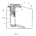
- Fig. 1 includes the well-known Fuel supply system, a cover 3, which is mounted on the upper surface of a fuel tank 1 to close an opening 4, which is formed in the upper wall.
- the cover 3 is made of a plastic and includes a tubular portion that extends into the interior of the fuel tank 11.
- a pump housing 16 is mounted at the lower end of the tubular portion.
- a fuel pump 2 is disposed within the pump housing 16.
- a controller 18 for controlling an engine of the fuel pump 2 is accommodated within a recessed portion.
- the control device comprises a ground connection.
- An electrically conductive wall of the tubular portion is electrically connected to the ground terminal of the controller.
- the mounting of the ground and the introduction of the grounding spring is associated with great expense. You also need an additional, loose component, which establishes the connection between pump and tank.
- a tank in particular a fuel tank, at least comprising an at least partially electrically conductive container, an electrical installation part, which is arranged inside the fuel tank, a cover which closes an opening for the electrical installation part, which in an upper portion is formed of the fuel tank, wherein the cover comprises at least one connector-and wherein a ground strap a Massepin a Plug connection with at least one conductive area of the fuel tank connects.
- the solution according to the invention has the advantage that the fuel tank contains a ground strap, which is cast in the plastic of the cover. By this measure, the number of parts decreases because the ground strap is cast securely in the cover. Also the risk that the mass connection no longer exists after a service case is minimized.
- the ground strap is designed so that it is partially cast on the surface of the cover.
- the closure part makes direct contact with the tank and enables a safe short to ground.
- the ground strap consists of a metal foil.
- a metal foil is easy to insert as insert in the injection mold of the cover and then to overmold.
- the ground strap is made of a conductive plastic.
- the cover can be produced in a simple manner with a two-component injection-molding process.
- the fuel tank with the cover to a ground pin, which establishes the short to ground with the ground strap.
- FIG. 2 shows a plan view of a cover 3.
- the cover 3 has an outer flange portion 3b, which forms an edge.
- the inner portion 3a of the cover bulges in the embodiment of the drawing planes to the rear.
- the cover 3 closes an opening in a fuel tank, for example a service opening for a fuel pump or other electrical installation part.
- the cover has in this embodiment openings 6, which are provided for example for a fuel line.
- a connector 5 is indicated in the lower part of the cover 3, a connector 5 is indicated.
- the connector 5 has a plurality of pins.
- the electrical component is supplied with electrical energy.
- Dotted is a grounding strap 7, which extends from the ground pin 8 to the flange 3b.
- the course is curved as an example or shown kinked, but also a straight connection between ground pin 8 and flange 3b is advantageous.
- the cover 3 shows the inner area 3a and the flange area 3b.
- the ground pin 8 extends from the top of the inner region 3a at least to the ground strap.
- the ground strap 7 is encapsulated. It runs from the ground pin 8 starting to the edge of the cover 3. There it follows the, in this case, stepped configuration and extends in the plastic upwards and occurs in the area 7b to the surface.
- the ground strap 7 extends only on one side overmoulded on the surface of the flange region 3b. This means that the grounding strip 7 extends over its entire course in a region 7a which is overmolded on both sides and is applied to the surface only in the region of the flange 3b in which it necessarily comes into contact with the closure part
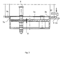
- FIG. 3 the installation of the cover 3 in the fuel tank 1 is indicated.
- the container 11 of the fuel tank 1 has a receptacle 9.
- This recording is either imprinted in the material or applied in any other way, for example, welded.
- the cover 3 is applied.
- a suitable receiving ring 10 the cover is connected to the container 11. It is possible to use a threaded receiving ring or to make recording and receiving ring so that a snap connection can be produced.
- the receiving ring 10 which consists of at least on its inside of a metallic active substance, the short to ground of the ground strap, which extends along the Flansch Structure Kunststoffes 3B via the receiving ring to the container of the fuel tank of the manufactured.
- a metallic ground strap is used, which is inserted in the production of the cover 3 in the injection mold and molded. In this case, two different regions are produced, a region 7a coated on both sides and a region 7b which is overmolded on one side.
- An alternative solution is a two-component production of the cover. In this case, a conductive area made of a conductive plastic is injected onto a first plastic component, which is insulating, and this in turn is covered by an insulating plastic.
- the Indian FIG. 3 shown Massepin 8 may be part of a connector.
- the connector is used in the simplest case for the power supply of an electrical component.
- the connector 5 is in FIG. 3 not shown. He is not necessarily necessary for the execution of the invention. It would also be possible to design the invention in such a way that a ground pin is connected to the vehicle via a separate ground line and is not used in combination with an electrical line.
- the fuel tank 1 is made entirely of metallic material. It is also possible to use a fuel tank that includes some plastic.
Abstract
Es wird ein Tank, der mindestens einen mindestens teilweise elektrisch leitfähigen Behälter, ein elektrisches Einbauteil, das innerhalb des Kraftstofftanks angeordnet ist, und eine Abdeckung , die eine Öffnung für das elektrische Bauteil verschließt, vorgeschlagen, der eine Erdung auf einfache Weise ermöglicht.It is proposed a tank, the at least one at least partially electrically conductive container, an electrical fitting, which is disposed within the fuel tank, and a cover which closes an opening for the electrical component, which allows a ground in a simple manner.
Description
Die Erfindung geht aus von einem Tank, im speziellen einen Kraftstofftank, der mindestens einen zumindest teilweise elektrisch leitfähigen Behälter, ein elektrisches Einbauteil, das innerhalb des Tanks angeordnet ist, eine Abdeckung , die eine Öffnung für das elektrische Einbauteil verschließt, umfasst.The invention is based on a tank, in particular a fuel tank, which comprises at least one at least partially electrically conductive container, an electrical installation part which is arranged inside the tank, a cover which closes an opening for the electrical installation part.
Bei Tanksystemen ist die Anforderung, eine Erdung des Tanks für die Ableitung beziehungsweise Verhinderung einer möglichen statischen Aufladung im Fahrzeug vorzusehen. Herkömmlich wird diese Erdung entweder bei Stahltanks außen durch Anbringung von Bolzen mit Muttern und/oder Laschen am Tank erreicht, wobei diese Bolzen und/oder Laschen mit Hilfe eines Massebandes mit der Karosseriemasse verbunden sind, oder innenliegend mit Bolzen und/oder Lasche und einem Masseband, welches mit der Masse eines elektrischen Einbauteiles beispielsweise eines Fördermoduls-verbunden ist. Das Verschweißen von Bolzen und/oder Laschen und die Montage des Massebandes sowie die Absicherung der durchgeführten Montage durch Abfragen, bewirken einen erhöhten Kostenaufwand. Im Fall eines Services besteht das Risiko, dass eine fehlende Erdung bei fehlender Verbindung mit der Masseleitung entsteht.For tank systems, the requirement is to provide a grounding of the tank for the dissipation or prevention of possible static charge in the vehicle. Conventionally, this grounding is achieved either in steel tanks outside by attaching bolts with nuts and / or tabs on the tank, these bolts and / or tabs are connected by means of a ground strap to the body ground, or inside with bolts and / or tab and a ground strap which is connected to the mass of an electrical component, for example, a conveyor module. The welding of bolts and / or tabs and the assembly of the ground strap and the protection of the performed assembly by queries, cause an increased cost. In the case of a service, there is the risk that a missing grounding will occur if there is no connection to the ground line.
Ein bekanntes Kraftstoffzufuhrsystem mit einer Erdung ist in der
Auch in diesem Beispiel des Standes der Technik ist die Montage der Erdung und das Einbringen der Erdungsfeder mit hohem Aufwand verbunden. Zudem braucht man ein zusätzliches, loses Bauteil, das die Verbindung zwischen Pumpe und Tank herstellt.A known fuel supply system with a ground is in the
Also in this example of the prior art, the mounting of the ground and the introduction of the grounding spring is associated with great expense. You also need an additional, loose component, which establishes the connection between pump and tank.
Es ist daher Aufgabe der Erfindung einen Tank mit einer Erdung bereitzustellen, wobei die Erdung zuverlässig und ohne zusätzliche Montage von einzelnen Bauteilen erfolgt.It is therefore an object of the invention to provide a tank with a ground, wherein the grounding is reliable and without additional assembly of individual components.
Die Aufgabe wird gelöst durch einen Tank, im speziellen einen Kraftstofftank, mindestens umfassend einen mindestens teilweise elektrisch leitfähigen Behälter, ein elektrisches Einbauteil, das innerhalb des Kraftstofftanks angeordnet ist, eine Abdeckung , die eine Öffnung für das elektrische Einbauteil verschließt, die in einem oberen Abschnitt des Kraftstofftanks ausgebildet ist, wobei die Abdeckung mindestens eine Steckverbindung-umfasst und wobei ein Masseband einen Massepin einer Steckverbindung mit mindestens einem leitfähigen Bereich des Kraftstofftanks verbindet.The object is achieved by a tank, in particular a fuel tank, at least comprising an at least partially electrically conductive container, an electrical installation part, which is arranged inside the fuel tank, a cover which closes an opening for the electrical installation part, which in an upper portion is formed of the fuel tank, wherein the cover comprises at least one connector-and wherein a ground strap a Massepin a Plug connection with at least one conductive area of the fuel tank connects.
Über die Stromversorgung des elektrischen Bauteiles gibt es einen Masseanschluss direkt zur Karosseriemasse des Fahrzeugs. Durch die Verbindung des Masseanschlusses und durch das Anstecken der Stromversorgung am Verschlussdeckel am Tank wird eine zuverlässige und wartungsneutrale Masseverbindung zur Verfügung gestellt.About the power supply of the electrical component, there is a ground connection directly to the body ground of the vehicle. By connecting the ground connection and by plugging the power supply to the cap on the tank a reliable and maintenance-neutral ground connection is provided.
Die erfindungsgemäße Lösung hat den Vorteil, dass der Kraftstofftank ein Masseband enthält, das im Kunststoff der Abdeckung eingegossen ist. Durch diese Maßnahme vermindert sich die Anzahl der Teile, da das Masseband sicher in der Abdeckung eingegossen ist. Auch das Risiko, dass nach einem Servicefall die Massenanbindung nicht mehr existiert wird minimiert.The solution according to the invention has the advantage that the fuel tank contains a ground strap, which is cast in the plastic of the cover. By this measure, the number of parts decreases because the ground strap is cast securely in the cover. Also the risk that the mass connection no longer exists after a service case is minimized.
Vorteilhafterweise ist das Masseband so ausgelegt, dass es teilweise auf der Oberfläche der Abdeckung eingegossen ist. Dadurch wird über das Verschlussteil ein direkter Kontakt mit dem Tank hergestellt und ein sicherer Masseschluss ermöglicht.Advantageously, the ground strap is designed so that it is partially cast on the surface of the cover. As a result, the closure part makes direct contact with the tank and enables a safe short to ground.
Vorteilhafterweise besteht das Masseband aus einer Metallfolie. Eine Metallfolie ist als Einlage einfach in die Spritzform der Abdeckung einzulegen und anschließend zu umspritzen.Advantageously, the ground strap consists of a metal foil. A metal foil is easy to insert as insert in the injection mold of the cover and then to overmold.
Es ist weiterhin von Vorteil, wenn das Masseband aus einem leitfähigen Kunststoff hergestellt ist. Dann lässt sich die Abdeckung auf einfache Art und Weise mit einem zwei Komponenten Spritz -Gussverfahren herstellen. Vorteilhafterweise weist der Kraftstofftank mit der Abdeckung einen Massepin auf, der den Masseschluss mit dem Masseband herstellt.It is also advantageous if the ground strap is made of a conductive plastic. Then the cover can be produced in a simple manner with a two-component injection-molding process. Advantageously, the fuel tank with the cover to a ground pin, which establishes the short to ground with the ground strap.
Die Erfindung wird nachfolgend beispielhaft unter Bezugnahme auf die beigefügte Zeichnung beschrieben.
-
Fig. 1 zeigt eine schematische Darstellung des Standes der Technik -
Fig. 2 zeigt eine Aufsicht auf eine erfindungsgemäße Abdeckung, -
Fig. 3 zeigt einen Schnitt durch die erfindungsgemäße Abdeckung.
-
Fig. 1 shows a schematic representation of the prior art -
Fig. 2 shows a plan view of a cover according to the invention, -
Fig. 3 shows a section through the cover according to the invention.
Die erfindungsgemäße Lösung wird anhand eines Beispiels aus den
Im Schnittbild der
Im Schnittbild ist zudem ein Anschluss zu erkennen der in der Öffnung 6 angebracht ist. Der Massepin 8 erstreckt sich von der Oberseite des Innenbereichs 3a mindestens bis zum Masseband. Innerhalb der Kunststoffschicht des Innenbereiches 3a ist das Masseband 7 umspritzt. Es verläuft vom Massepin 8 ausgehend bis zum Rand der Abdeckung 3. Dort folgt es der, in diesem Fall, treppenförmigen Ausgestaltung und verläuft im Kunststoff nach oben und tritt im Bereich 7b an die Oberfläche. Im Bereich 7b verläuft das Masseband 7 nur noch einseitig umspritzt auf der Oberfläche des Flanschbereiches 3b. Das bedeutet, dass das Masseband 7 über seinen gesamten Verlauf in einem beidseitig umspritzten Bereich 7a verläuft und nur im Bereich des Flansches 3b, in dem es zwingend zur Berührung mit dem Verschlussteil kommt, an der Oberfläche aufgebracht istIn addition, a connection can be seen in the sectional view, which is mounted in the
In
Über den Aufnahmering 10 der mindestens auf seiner Innenseite aus einem metallischen Wirkstoff besteht, wird der Masseschluss vom Masseband, das sich entlang des Flanschflächebereiches 3B erstreckt über den Aufnahmering zum Behälter des Kraftstofftankes des hergestellt. In einer Ausführungsform der Erfindung wird ein metallisches Masseband verwendet, das bei der Herstellung der Abdeckung 3 in das Spritzwerkzeug eingelegt und umspritzt wird. Dabei werden zwei unterschiedliche Bereiche hergestellt, ein beidseitig umspritzter Bereich 7a sowie ein einseitig umspritzter Bereich 7b . Eine alternative Lösung stellt eine Zweikomponentenherstellung der Abdeckung dar. Dabei wird auf eine erste Kunststoffkomponente, die isolierende ist, ein leitender Bereich aus einem leitfähigen Kunststoff eingespritzt und dieser wiederum von einem isolierenden Kunststoff abgedeckt.About the
Der in der
Es ist auch nicht notwendig, dass der Kraftstofftank 1 vollständig aus metallischem Werkstoff besteht. Es ist auch möglich einen Kraftstofftank zu verwenden, der teilweise Kunststoff beinhaltet.It is also not necessary that the
Die Ausführung wurde in Bezug auf einen Kraftstoffatnk beschrieben ist aber für jeden zu erdenden Tank anwendbar.The design has been described with reference to a fuel tank but is applicable to every tank to be grounded.
- 11
- KraftstofftankFuel tank
- 22
- KraftstoffpumpeFuel pump
- 33
- Abdeckungcover
- 3a3a
- Innenbereichinterior
- 3b3b
- Flanschbereichflange
- 44
- Öffnungopening
- 55
- SteckverbinderConnectors
- 66
- Öffnungopening
- 77
- Massebandground strap
- 7a7a
- beidseitig umspritzter Bereichdouble-sided overmolded area
- 7b7b
- einseitig umspitzter Bereichunilaterally pointed area
- 88th
- Massepinground pin
- 99
- Aufnahmeadmission
- 1010
- Aufnahmeringreceiving ring
- 1111
- Behältercontainer
- 1616
- Pumpengehäusepump housing
- 1818
- Steuereinrichtungcontrol device
Claims (9)
Priority Applications (3)
| Application Number | Priority Date | Filing Date | Title |
|---|---|---|---|
| EP13188994.1A EP2863041B1 (en) | 2013-10-16 | 2013-10-16 | Tank |
| CN201410526598.8A CN104564458B (en) | 2013-10-16 | 2014-10-09 | Case |
| US14/515,775 US9872371B2 (en) | 2013-10-16 | 2014-10-16 | Tank |
Applications Claiming Priority (1)
| Application Number | Priority Date | Filing Date | Title |
|---|---|---|---|
| EP13188994.1A EP2863041B1 (en) | 2013-10-16 | 2013-10-16 | Tank |
Publications (2)
| Publication Number | Publication Date |
|---|---|
| EP2863041A1 true EP2863041A1 (en) | 2015-04-22 |
| EP2863041B1 EP2863041B1 (en) | 2016-03-23 |
Family
ID=49356331
Family Applications (1)
| Application Number | Title | Priority Date | Filing Date |
|---|---|---|---|
| EP13188994.1A Not-in-force EP2863041B1 (en) | 2013-10-16 | 2013-10-16 | Tank |
Country Status (3)
| Country | Link |
|---|---|
| US (1) | US9872371B2 (en) |
| EP (1) | EP2863041B1 (en) |
| CN (1) | CN104564458B (en) |
Cited By (1)
| Publication number | Priority date | Publication date | Assignee | Title |
|---|---|---|---|---|
| DE102014225158A1 (en) * | 2014-12-08 | 2016-06-23 | Bayerische Motoren Werke Aktiengesellschaft | Fuel storage system and method for assembling a fuel storage system |
Families Citing this family (2)
| Publication number | Priority date | Publication date | Assignee | Title |
|---|---|---|---|---|
| CN107228037B (en) * | 2016-03-23 | 2020-10-27 | 上海欧菲滤清器有限公司 | Fuel filter |
| CN106550573A (en) * | 2016-11-02 | 2017-03-29 | 芜湖光荣网络科技有限公司 | A kind of shatter-resistant protection shell for electronic product |
Citations (5)
| Publication number | Priority date | Publication date | Assignee | Title |
|---|---|---|---|---|
| US6206035B1 (en) * | 1997-08-30 | 2001-03-27 | Mannesmann Vdo Ag | Safety device for a fuel tank |
| US20030084884A1 (en) * | 2001-11-08 | 2003-05-08 | Ulf Sawert | Grounded fuel delivery module for fuel system |
| US20040065144A1 (en) * | 2002-10-02 | 2004-04-08 | Mitsubishi Denki Kabushiki Kaisha | Fuel pump module and vehicle fuel tank internal pressure sensor |
| US20060219318A1 (en) * | 2005-04-05 | 2006-10-05 | Ti Group Automotive Systems, Llc | Electrostatic charge control for in-tank fuel module components |
| DE102007021584A1 (en) | 2006-05-11 | 2007-11-22 | Aisan Kogyo K.K., Obu | Fuel supply system for supplying fuel of vehicle fuel tank, has fuel pump arranged inside fuel tank, and cover, which locks opening, is formed in upper section of fuel tank, and control device controls operation of motor |
Family Cites Families (3)
| Publication number | Priority date | Publication date | Assignee | Title |
|---|---|---|---|---|
| JP3822864B2 (en) * | 2003-03-24 | 2006-09-20 | 八千代工業株式会社 | Fuel tank grounding structure |
| CN1880128A (en) * | 2005-04-05 | 2006-12-20 | Ti集团车辆系统有限责任公司 | Electrostatic charge control for in-tank fuel module components |
| DE102011081967A1 (en) * | 2011-09-01 | 2013-03-07 | Robert Bosch Gmbh | Earthing of a fuel delivery module by means of a sprayed electrically conductive structure |
-
2013
- 2013-10-16 EP EP13188994.1A patent/EP2863041B1/en not_active Not-in-force
-
2014
- 2014-10-09 CN CN201410526598.8A patent/CN104564458B/en active Active
- 2014-10-16 US US14/515,775 patent/US9872371B2/en active Active
Patent Citations (5)
| Publication number | Priority date | Publication date | Assignee | Title |
|---|---|---|---|---|
| US6206035B1 (en) * | 1997-08-30 | 2001-03-27 | Mannesmann Vdo Ag | Safety device for a fuel tank |
| US20030084884A1 (en) * | 2001-11-08 | 2003-05-08 | Ulf Sawert | Grounded fuel delivery module for fuel system |
| US20040065144A1 (en) * | 2002-10-02 | 2004-04-08 | Mitsubishi Denki Kabushiki Kaisha | Fuel pump module and vehicle fuel tank internal pressure sensor |
| US20060219318A1 (en) * | 2005-04-05 | 2006-10-05 | Ti Group Automotive Systems, Llc | Electrostatic charge control for in-tank fuel module components |
| DE102007021584A1 (en) | 2006-05-11 | 2007-11-22 | Aisan Kogyo K.K., Obu | Fuel supply system for supplying fuel of vehicle fuel tank, has fuel pump arranged inside fuel tank, and cover, which locks opening, is formed in upper section of fuel tank, and control device controls operation of motor |
Cited By (1)
| Publication number | Priority date | Publication date | Assignee | Title |
|---|---|---|---|---|
| DE102014225158A1 (en) * | 2014-12-08 | 2016-06-23 | Bayerische Motoren Werke Aktiengesellschaft | Fuel storage system and method for assembling a fuel storage system |
Also Published As
| Publication number | Publication date |
|---|---|
| US20150103463A1 (en) | 2015-04-16 |
| CN104564458B (en) | 2019-03-19 |
| EP2863041B1 (en) | 2016-03-23 |
| CN104564458A (en) | 2015-04-29 |
| US9872371B2 (en) | 2018-01-16 |
Similar Documents
| Publication | Publication Date | Title |
|---|---|---|
| DE3838285C2 (en) | Electric motor, in particular small electric motor for driving windshield wiper systems in motor vehicles | |
| DE19934346B4 (en) | Device for fastening and sealing a heating element in a windscreen washer pipe | |
| DE112008003276B4 (en) | A method of forming a watertight connection section and wiring harness provided with a waterproof connection portion formed by the method | |
| DE19921539B4 (en) | Connector for a fuel pump of a motor vehicle | |
| DE112014002122T5 (en) | Interconnects | |
| DE102013020094A1 (en) | Electric motor, in particular radiator fan motor | |
| EP2996227B1 (en) | Fan housing, especially for a fan for a vehicle heating device | |
| EP2863041B1 (en) | Tank | |
| DE202005015588U1 (en) | Component carrier with plug connector, for electrical and electronic components in vehicle door locks, is selected for desired plug connector activation | |
| DE102016103439A1 (en) | Contact point of a flat conductor | |
| DE102014205744B4 (en) | Control unit for a vehicle heater | |
| DE60207562T2 (en) | Connection assembly for the electrical connection of an electric motor | |
| EP2704544B1 (en) | Sensor assembly | |
| DE102018210892A1 (en) | Plug connection element for a motor vehicle and method for producing such a plug connection element | |
| EP1257448A1 (en) | System for heating liquid in a conduit system | |
| DE102013215365A1 (en) | Electric transmission control device and manufacturing method | |
| DE112013004137B4 (en) | Electrical distributor | |
| DE3417266A1 (en) | DC motor, especially an electrical fuel pump for motor vehicles | |
| DE102013021409A1 (en) | Watertight screw contact for contacting an electrical or electronic device | |
| DE102010063614A1 (en) | Method for producing a sensor assembly | |
| WO2014012752A1 (en) | Fan with electrical lead injection moulded into the housing | |
| DE112018005157T5 (en) | MOTOR AND ELECTRIC POWER STEERING SYSTEM | |
| WO2018082992A1 (en) | Method for producing a plug, which is provided with a plastic injection-moulded encapsulation, for a fuel pump which is to be arranged in a fuel tank of a motor vehicle | |
| DE2702404C2 (en) | Fuel delivery unit with an interference suppression device | |
| DE102012102937A1 (en) | Safety nut for fastening component in high voltage region within electrical energy storage device e.g. battery or battery module, has insulating structure that is provided to surround electrically conductive thread material |
Legal Events
| Date | Code | Title | Description |
|---|---|---|---|
| PUAI | Public reference made under article 153(3) epc to a published international application that has entered the european phase |
Free format text: ORIGINAL CODE: 0009012 |
|
| 17P | Request for examination filed |
Effective date: 20131016 |
|
| AK | Designated contracting states |
Kind code of ref document: A1 Designated state(s): AL AT BE BG CH CY CZ DE DK EE ES FI FR GB GR HR HU IE IS IT LI LT LU LV MC MK MT NL NO PL PT RO RS SE SI SK SM TR |
|
| AX | Request for extension of the european patent |
Extension state: BA ME |
|
| R17P | Request for examination filed (corrected) |
Effective date: 20150730 |
|
| RBV | Designated contracting states (corrected) |
Designated state(s): AL AT BE BG CH CY CZ DE DK EE ES FI FR GB GR HR HU IE IS IT LI LT LU LV MC MK MT NL NO PL PT RO RS SE SI SK SM TR |
|
| GRAP | Despatch of communication of intention to grant a patent |
Free format text: ORIGINAL CODE: EPIDOSNIGR1 |
|
| RIC1 | Information provided on ipc code assigned before grant |
Ipc: F02D 33/00 20060101ALI20151021BHEP Ipc: F02M 37/08 20060101AFI20151021BHEP Ipc: F02M 37/10 20060101ALI20151021BHEP Ipc: B60K 15/03 20060101ALN20151021BHEP Ipc: H05F 3/02 20060101ALI20151021BHEP |
|
| RIC1 | Information provided on ipc code assigned before grant |
Ipc: F02D 33/00 20060101ALI20151028BHEP Ipc: F02M 37/08 20060101AFI20151028BHEP Ipc: B60K 15/03 20060101ALN20151028BHEP Ipc: H05F 3/02 20060101ALI20151028BHEP Ipc: F02M 37/10 20060101ALI20151028BHEP |
|
| INTG | Intention to grant announced |
Effective date: 20151118 |
|
| GRAS | Grant fee paid |
Free format text: ORIGINAL CODE: EPIDOSNIGR3 |
|
| GRAA | (expected) grant |
Free format text: ORIGINAL CODE: 0009210 |
|
| AK | Designated contracting states |
Kind code of ref document: B1 Designated state(s): AL AT BE BG CH CY CZ DE DK EE ES FI FR GB GR HR HU IE IS IT LI LT LU LV MC MK MT NL NO PL PT RO RS SE SI SK SM TR |
|
| REG | Reference to a national code |
Ref country code: GB Ref legal event code: FG4D Free format text: NOT ENGLISH |
|
| REG | Reference to a national code |
Ref country code: CH Ref legal event code: EP |
|
| REG | Reference to a national code |
Ref country code: AT Ref legal event code: REF Ref document number: 783421 Country of ref document: AT Kind code of ref document: T Effective date: 20160415 |
|
| REG | Reference to a national code |
Ref country code: IE Ref legal event code: FG4D Free format text: LANGUAGE OF EP DOCUMENT: GERMAN |
|
| REG | Reference to a national code |
Ref country code: DE Ref legal event code: R096 Ref document number: 502013002268 Country of ref document: DE |
|
| REG | Reference to a national code |
Ref country code: LT Ref legal event code: MG4D |
|
| REG | Reference to a national code |
Ref country code: NL Ref legal event code: MP Effective date: 20160323 |
|
| PG25 | Lapsed in a contracting state [announced via postgrant information from national office to epo] |
Ref country code: GR Free format text: LAPSE BECAUSE OF FAILURE TO SUBMIT A TRANSLATION OF THE DESCRIPTION OR TO PAY THE FEE WITHIN THE PRESCRIBED TIME-LIMIT Effective date: 20160624 Ref country code: HR Free format text: LAPSE BECAUSE OF FAILURE TO SUBMIT A TRANSLATION OF THE DESCRIPTION OR TO PAY THE FEE WITHIN THE PRESCRIBED TIME-LIMIT Effective date: 20160323 Ref country code: FI Free format text: LAPSE BECAUSE OF FAILURE TO SUBMIT A TRANSLATION OF THE DESCRIPTION OR TO PAY THE FEE WITHIN THE PRESCRIBED TIME-LIMIT Effective date: 20160323 Ref country code: NO Free format text: LAPSE BECAUSE OF FAILURE TO SUBMIT A TRANSLATION OF THE DESCRIPTION OR TO PAY THE FEE WITHIN THE PRESCRIBED TIME-LIMIT Effective date: 20160623 |
|
| PG25 | Lapsed in a contracting state [announced via postgrant information from national office to epo] |
Ref country code: NL Free format text: LAPSE BECAUSE OF FAILURE TO SUBMIT A TRANSLATION OF THE DESCRIPTION OR TO PAY THE FEE WITHIN THE PRESCRIBED TIME-LIMIT Effective date: 20160323 Ref country code: LV Free format text: LAPSE BECAUSE OF FAILURE TO SUBMIT A TRANSLATION OF THE DESCRIPTION OR TO PAY THE FEE WITHIN THE PRESCRIBED TIME-LIMIT Effective date: 20160323 Ref country code: LT Free format text: LAPSE BECAUSE OF FAILURE TO SUBMIT A TRANSLATION OF THE DESCRIPTION OR TO PAY THE FEE WITHIN THE PRESCRIBED TIME-LIMIT Effective date: 20160323 Ref country code: SE Free format text: LAPSE BECAUSE OF FAILURE TO SUBMIT A TRANSLATION OF THE DESCRIPTION OR TO PAY THE FEE WITHIN THE PRESCRIBED TIME-LIMIT Effective date: 20160323 Ref country code: RS Free format text: LAPSE BECAUSE OF FAILURE TO SUBMIT A TRANSLATION OF THE DESCRIPTION OR TO PAY THE FEE WITHIN THE PRESCRIBED TIME-LIMIT Effective date: 20160323 |
|
| REG | Reference to a national code |
Ref country code: FR Ref legal event code: PLFP Year of fee payment: 4 |
|
| PG25 | Lapsed in a contracting state [announced via postgrant information from national office to epo] |
Ref country code: IS Free format text: LAPSE BECAUSE OF FAILURE TO SUBMIT A TRANSLATION OF THE DESCRIPTION OR TO PAY THE FEE WITHIN THE PRESCRIBED TIME-LIMIT Effective date: 20160723 Ref country code: EE Free format text: LAPSE BECAUSE OF FAILURE TO SUBMIT A TRANSLATION OF THE DESCRIPTION OR TO PAY THE FEE WITHIN THE PRESCRIBED TIME-LIMIT Effective date: 20160323 Ref country code: PL Free format text: LAPSE BECAUSE OF FAILURE TO SUBMIT A TRANSLATION OF THE DESCRIPTION OR TO PAY THE FEE WITHIN THE PRESCRIBED TIME-LIMIT Effective date: 20160323 |
|
| PG25 | Lapsed in a contracting state [announced via postgrant information from national office to epo] |
Ref country code: SK Free format text: LAPSE BECAUSE OF FAILURE TO SUBMIT A TRANSLATION OF THE DESCRIPTION OR TO PAY THE FEE WITHIN THE PRESCRIBED TIME-LIMIT Effective date: 20160323 Ref country code: PT Free format text: LAPSE BECAUSE OF FAILURE TO SUBMIT A TRANSLATION OF THE DESCRIPTION OR TO PAY THE FEE WITHIN THE PRESCRIBED TIME-LIMIT Effective date: 20160725 Ref country code: SM Free format text: LAPSE BECAUSE OF FAILURE TO SUBMIT A TRANSLATION OF THE DESCRIPTION OR TO PAY THE FEE WITHIN THE PRESCRIBED TIME-LIMIT Effective date: 20160323 Ref country code: ES Free format text: LAPSE BECAUSE OF FAILURE TO SUBMIT A TRANSLATION OF THE DESCRIPTION OR TO PAY THE FEE WITHIN THE PRESCRIBED TIME-LIMIT Effective date: 20160323 Ref country code: CZ Free format text: LAPSE BECAUSE OF FAILURE TO SUBMIT A TRANSLATION OF THE DESCRIPTION OR TO PAY THE FEE WITHIN THE PRESCRIBED TIME-LIMIT Effective date: 20160323 Ref country code: RO Free format text: LAPSE BECAUSE OF FAILURE TO SUBMIT A TRANSLATION OF THE DESCRIPTION OR TO PAY THE FEE WITHIN THE PRESCRIBED TIME-LIMIT Effective date: 20160323 |
|
| PG25 | Lapsed in a contracting state [announced via postgrant information from national office to epo] |
Ref country code: IT Free format text: LAPSE BECAUSE OF FAILURE TO SUBMIT A TRANSLATION OF THE DESCRIPTION OR TO PAY THE FEE WITHIN THE PRESCRIBED TIME-LIMIT Effective date: 20160323 |
|
| REG | Reference to a national code |
Ref country code: DE Ref legal event code: R097 Ref document number: 502013002268 Country of ref document: DE |
|
| PLBE | No opposition filed within time limit |
Free format text: ORIGINAL CODE: 0009261 |
|
| STAA | Information on the status of an ep patent application or granted ep patent |
Free format text: STATUS: NO OPPOSITION FILED WITHIN TIME LIMIT |
|
| PG25 | Lapsed in a contracting state [announced via postgrant information from national office to epo] |
Ref country code: DK Free format text: LAPSE BECAUSE OF FAILURE TO SUBMIT A TRANSLATION OF THE DESCRIPTION OR TO PAY THE FEE WITHIN THE PRESCRIBED TIME-LIMIT Effective date: 20160323 |
|
| PG25 | Lapsed in a contracting state [announced via postgrant information from national office to epo] |
Ref country code: BE Free format text: LAPSE BECAUSE OF NON-PAYMENT OF DUE FEES Effective date: 20161031 Ref country code: BG Free format text: LAPSE BECAUSE OF FAILURE TO SUBMIT A TRANSLATION OF THE DESCRIPTION OR TO PAY THE FEE WITHIN THE PRESCRIBED TIME-LIMIT Effective date: 20160623 |
|
| 26N | No opposition filed |
Effective date: 20170102 |
|
| PG25 | Lapsed in a contracting state [announced via postgrant information from national office to epo] |
Ref country code: SI Free format text: LAPSE BECAUSE OF FAILURE TO SUBMIT A TRANSLATION OF THE DESCRIPTION OR TO PAY THE FEE WITHIN THE PRESCRIBED TIME-LIMIT Effective date: 20160323 |
|
| REG | Reference to a national code |
Ref country code: CH Ref legal event code: PL |
|
| REG | Reference to a national code |
Ref country code: IE Ref legal event code: MM4A |
|
| PG25 | Lapsed in a contracting state [announced via postgrant information from national office to epo] |
Ref country code: LI Free format text: LAPSE BECAUSE OF NON-PAYMENT OF DUE FEES Effective date: 20161031 Ref country code: CH Free format text: LAPSE BECAUSE OF NON-PAYMENT OF DUE FEES Effective date: 20161031 |
|
| PG25 | Lapsed in a contracting state [announced via postgrant information from national office to epo] |
Ref country code: LU Free format text: LAPSE BECAUSE OF NON-PAYMENT OF DUE FEES Effective date: 20161016 |
|
| REG | Reference to a national code |
Ref country code: FR Ref legal event code: PLFP Year of fee payment: 5 |
|
| PG25 | Lapsed in a contracting state [announced via postgrant information from national office to epo] |
Ref country code: IE Free format text: LAPSE BECAUSE OF NON-PAYMENT OF DUE FEES Effective date: 20161016 |
|
| REG | Reference to a national code |
Ref country code: BE Ref legal event code: MM Effective date: 20161031 |
|
| PG25 | Lapsed in a contracting state [announced via postgrant information from national office to epo] |
Ref country code: HU Free format text: LAPSE BECAUSE OF FAILURE TO SUBMIT A TRANSLATION OF THE DESCRIPTION OR TO PAY THE FEE WITHIN THE PRESCRIBED TIME-LIMIT; INVALID AB INITIO Effective date: 20131016 |
|
| PG25 | Lapsed in a contracting state [announced via postgrant information from national office to epo] |
Ref country code: MT Free format text: LAPSE BECAUSE OF FAILURE TO SUBMIT A TRANSLATION OF THE DESCRIPTION OR TO PAY THE FEE WITHIN THE PRESCRIBED TIME-LIMIT Effective date: 20160323 Ref country code: CY Free format text: LAPSE BECAUSE OF FAILURE TO SUBMIT A TRANSLATION OF THE DESCRIPTION OR TO PAY THE FEE WITHIN THE PRESCRIBED TIME-LIMIT Effective date: 20160323 Ref country code: MK Free format text: LAPSE BECAUSE OF FAILURE TO SUBMIT A TRANSLATION OF THE DESCRIPTION OR TO PAY THE FEE WITHIN THE PRESCRIBED TIME-LIMIT Effective date: 20160323 Ref country code: MC Free format text: LAPSE BECAUSE OF FAILURE TO SUBMIT A TRANSLATION OF THE DESCRIPTION OR TO PAY THE FEE WITHIN THE PRESCRIBED TIME-LIMIT Effective date: 20160323 |
|
| REG | Reference to a national code |
Ref country code: FR Ref legal event code: PLFP Year of fee payment: 6 |
|
| PG25 | Lapsed in a contracting state [announced via postgrant information from national office to epo] |
Ref country code: TR Free format text: LAPSE BECAUSE OF FAILURE TO SUBMIT A TRANSLATION OF THE DESCRIPTION OR TO PAY THE FEE WITHIN THE PRESCRIBED TIME-LIMIT Effective date: 20160323 Ref country code: AL Free format text: LAPSE BECAUSE OF FAILURE TO SUBMIT A TRANSLATION OF THE DESCRIPTION OR TO PAY THE FEE WITHIN THE PRESCRIBED TIME-LIMIT Effective date: 20160323 |
|
| REG | Reference to a national code |
Ref country code: AT Ref legal event code: MM01 Ref document number: 783421 Country of ref document: AT Kind code of ref document: T Effective date: 20181016 |
|
| PG25 | Lapsed in a contracting state [announced via postgrant information from national office to epo] |
Ref country code: AT Free format text: LAPSE BECAUSE OF NON-PAYMENT OF DUE FEES Effective date: 20181016 |
|
| REG | Reference to a national code |
Ref country code: DE Ref legal event code: R082 Ref document number: 502013002268 Country of ref document: DE Representative=s name: RAUSCH, GABRIELE, DIPL.-PHYS. DR.RER.NAT., DE Ref country code: DE Ref legal event code: R081 Ref document number: 502013002268 Country of ref document: DE Owner name: MAGNA ENERGY STORAGE SYSTEMS GESMBH, AT Free format text: FORMER OWNER: MAGNA STEYR FUEL SYSTEMS GESMBH, SINABELKIRCHEN, AT |
|
| PGFP | Annual fee paid to national office [announced via postgrant information from national office to epo] |
Ref country code: GB Payment date: 20211022 Year of fee payment: 9 Ref country code: DE Payment date: 20211020 Year of fee payment: 9 |
|
| PGFP | Annual fee paid to national office [announced via postgrant information from national office to epo] |
Ref country code: FR Payment date: 20211022 Year of fee payment: 9 |
|
| REG | Reference to a national code |
Ref country code: DE Ref legal event code: R119 Ref document number: 502013002268 Country of ref document: DE |
|
| GBPC | Gb: european patent ceased through non-payment of renewal fee |
Effective date: 20221016 |
|
| PG25 | Lapsed in a contracting state [announced via postgrant information from national office to epo] |
Ref country code: FR Free format text: LAPSE BECAUSE OF NON-PAYMENT OF DUE FEES Effective date: 20221031 Ref country code: DE Free format text: LAPSE BECAUSE OF NON-PAYMENT OF DUE FEES Effective date: 20230503 |
|
| PG25 | Lapsed in a contracting state [announced via postgrant information from national office to epo] |
Ref country code: GB Free format text: LAPSE BECAUSE OF NON-PAYMENT OF DUE FEES Effective date: 20221016 |