EP2862755A1 - Vehicle bonnet safety assembly - Google Patents
Vehicle bonnet safety assembly Download PDFInfo
- Publication number
- EP2862755A1 EP2862755A1 EP20130189457 EP13189457A EP2862755A1 EP 2862755 A1 EP2862755 A1 EP 2862755A1 EP 20130189457 EP20130189457 EP 20130189457 EP 13189457 A EP13189457 A EP 13189457A EP 2862755 A1 EP2862755 A1 EP 2862755A1
- Authority
- EP
- European Patent Office
- Prior art keywords
- bonnet
- elongated guide
- vehicle
- sliding
- actuators
- Prior art date
- Legal status (The legal status is an assumption and is not a legal conclusion. Google has not performed a legal analysis and makes no representation as to the accuracy of the status listed.)
- Granted
Links
- 230000007246 mechanism Effects 0.000 claims description 27
- 230000002265 prevention Effects 0.000 claims description 8
- 238000010586 diagram Methods 0.000 description 3
- 230000000452 restraining effect Effects 0.000 description 3
- 230000001133 acceleration Effects 0.000 description 2
- 206010039203 Road traffic accident Diseases 0.000 description 1
- 238000000034 method Methods 0.000 description 1
- 238000012986 modification Methods 0.000 description 1
- 230000004048 modification Effects 0.000 description 1
Images


Classifications
-
- B—PERFORMING OPERATIONS; TRANSPORTING
- B62—LAND VEHICLES FOR TRAVELLING OTHERWISE THAN ON RAILS
- B62D—MOTOR VEHICLES; TRAILERS
- B62D25/00—Superstructure or monocoque structure sub-units; Parts or details thereof not otherwise provided for
- B62D25/08—Front or rear portions
- B62D25/10—Bonnets or lids, e.g. for trucks, tractors, busses, work vehicles
- B62D25/105—Bonnets or lids, e.g. for trucks, tractors, busses, work vehicles for motor cars
-
- B—PERFORMING OPERATIONS; TRANSPORTING
- B60—VEHICLES IN GENERAL
- B60R—VEHICLES, VEHICLE FITTINGS, OR VEHICLE PARTS, NOT OTHERWISE PROVIDED FOR
- B60R21/00—Arrangements or fittings on vehicles for protecting or preventing injuries to occupants or pedestrians in case of accidents or other traffic risks
- B60R21/34—Protecting non-occupants of a vehicle, e.g. pedestrians
- B60R21/38—Protecting non-occupants of a vehicle, e.g. pedestrians using means for lifting bonnets
-
- B—PERFORMING OPERATIONS; TRANSPORTING
- B60—VEHICLES IN GENERAL
- B60R—VEHICLES, VEHICLE FITTINGS, OR VEHICLE PARTS, NOT OTHERWISE PROVIDED FOR
- B60R22/00—Safety belts or body harnesses in vehicles
-
- B—PERFORMING OPERATIONS; TRANSPORTING
- B62—LAND VEHICLES FOR TRAVELLING OTHERWISE THAN ON RAILS
- B62D—MOTOR VEHICLES; TRAILERS
- B62D25/00—Superstructure or monocoque structure sub-units; Parts or details thereof not otherwise provided for
- B62D25/08—Front or rear portions
- B62D25/10—Bonnets or lids, e.g. for trucks, tractors, busses, work vehicles
- B62D25/12—Parts or details thereof
-
- E—FIXED CONSTRUCTIONS
- E05—LOCKS; KEYS; WINDOW OR DOOR FITTINGS; SAFES
- E05C—BOLTS OR FASTENING DEVICES FOR WINGS, SPECIALLY FOR DOORS OR WINDOWS
- E05C17/00—Devices for holding wings open; Devices for limiting opening of wings or for holding wings open by a movable member extending between frame and wing; Braking devices, stops or buffers, combined therewith
-
- E—FIXED CONSTRUCTIONS
- E05—LOCKS; KEYS; WINDOW OR DOOR FITTINGS; SAFES
- E05C—BOLTS OR FASTENING DEVICES FOR WINGS, SPECIALLY FOR DOORS OR WINDOWS
- E05C17/00—Devices for holding wings open; Devices for limiting opening of wings or for holding wings open by a movable member extending between frame and wing; Braking devices, stops or buffers, combined therewith
- E05C17/60—Devices for holding wings open; Devices for limiting opening of wings or for holding wings open by a movable member extending between frame and wing; Braking devices, stops or buffers, combined therewith holding sliding wings open
Definitions
- the present invention relates to vehicle bonnet safety assembly, in particular for typical cars.
- the present technical concept addresses situations where a vehicle bonnet flips over the windscreen during an accidental opening or traffic accident. As it appears, despite typical latch mechanisms provided by vehicle manufacturers in the front-middle section of a bonnet, accidental bonnet opening happens in practice. Hence, what is required is a means to address safety issues during an accident when the first locking means fails.
- Bonnet safety assembly must thus address two major concerns that are first to prevent opening of the bonnet and second, if the opening is unavoidable, to provide means allowing for such opening of the bonnet that will not result in the driver's line of sight being blocked by the opened bonnet.
- the '467 publication does not address the safety issues during an accident when the first locking means fails.
- '624 provides a hood latching device comprising a first latch mechanism and a second latch member having a hooked member whereby the above described drawback of the conventional latching device is substantially eliminated by an improved hood latching device wherein the releasing movement of the hooked member of the second latching mechanism is prevented by a member cooperating with the first latching mechanism, and the possibility of accidental release of the second latch mechanism is thereby substantially eliminated.
- the object of the present invention is a vehicle bonnet safety assembly, the vehicle comprising: a bonnet; a windscreen; a chassis, to which the bonnet is hingedly joined by means of actuators; the assembly further comprises: an elongated guide fixedly mounted, and supported along its length, on the bottom side of the bonnet; a sliding member provided inside the elongated guide to slide along the length of the elongated guide until it engages a stop coupled to the elongated guide; whereas the sliding member is mounted in the elongated guide such that it is prevented from sliding out and sliding back the elongated guide thereby creating a field of visibility on the road for a driver when the bonnet flips over the windscreen.
- the actuators are mounted such that they are prevented from detaching from the sliding member.
- the actuators are pneumatic actuators wherein in each actuator a pneumatic valve allows the flow of a medium when the bonnet is being opened with a force below a threshold and prevents the flow of a medium when the bonnet is being opened with a force above a threshold.
- the mechanism for prevention of sliding back has a form of one or more locking elements that allow only one direction movement.
- the mechanism for prevention of sliding back comprises at least one locking pawl.
- any object on or in the vehicle has its own inertia.
- the inertia forces of different objects of the above are independent.
- the vehicle may be brought to an abrupt stop while its bonnet, thrown in an opposite direction, may flip over the vehicle's windscreen thereby obscuring the view on the road.
- Fig. 1 there is shown a car's (101) bonnet (105, 106) restraining mechanism, which includes a retractable strap (106) which is secured to a retraction mechanism (105) further secured to the car's chassis (107) or frame at one end and is secured to the car's bonnet (102) at an opposite end.
- the bonnet (102) is also hingedly joined with the chassis of the vehicle in order to provide normal opening function.
- the restraining mechanism at the car's chassis or frame end comprises the retraction mechanism (105) coupled to an inertia reel in the present embodiment located in the area typical for a headlight (the location may differ and the inertia reel may be mounted on (fastened to) the left of right side of the vehicle or at the front of the vehicle).
- the inertia reel mechanism may be such as the one disclosed in "Inertia reel mechanisms" - US 3578260 A or “Inertia locking retractor" - US 3917189 A or similar, allowing for a strap or belt to be automatically locked against extension when the bonnet rapidly moves relative to the vehicle's engine compartment with an acceleration above a predetermined acceleration.
- Such strap has the ability to extend and retract.
- the bonnet (102) may be opened easily when the strap is extended with a low to moderate force below a predetermined threshold, but in case a strong force is applied, above the predefined threshold, the strap will instantly tighten up and hold the bonnet secured in place (i.e in proximity to the engine compartment) and preventing it from flipping onto the windscreen (104).
- the retractable strap (106) is allowed to extend in case a force below a predetermined threshold is applied and retractable strap (106) is prevented from extending when a force above the predefined threshold is applied.
- bonnet restraining mechanism on the left and right side of the bonnet (102) accordingly.
- the strap has to have suitable strength to hold the opening bonnet when the bonnet rapidly accelerates and subsequently decelerates. Nevertheless, different materials and different width and/or thickness of the strap may be applied.
- Fig. 2A presents a schematic diagram of an enhancement of the assembly according to the present invention.
- the enhancement is to ensure driver's visibility of the road in case bonnet opening prevention mechanisms have failed.
- the car's (101) bonnet (102) may be opened and subsequently supported with two actuators (201) such as pneumatic actuators. There are typically two of such actuators (201), positioned on the left and right side of the bonnet (102), connecting the bonnet (102) with the chassis.
- the present invention introduces a mechanism between the top end of the actuator (201) and the bonnet (102).
- the mechanism includes an elongated guide (203) fixedly mounted, and supported along its length, on the bottom side of the bonnet (102).
- a sliding member (202) is provided inside the elongated guide (203) to slide along the length of the elongated guide (203) until it engages a stop (shown in details in Figs. 4B-4C ) coupled to the elongated guide (203).
- the sliding member (202) is mounted in the elongated guide (203) such that it will never slide out of the elongated guide (203) (the sliding member is prevented from sliding out of the elongated guide).
- the mechanism for prevention of sliding back may have a form of a latch.
- the obtained field of visibility may be different depending on the length of the applied sliding member (202) and the elongated guide (203).
- the actuators (201) are mounted such that they will never detach from the sliding member (202) (they are prevented from detaching from the sliding member (202) by means of for example screws).
- Fig. 3 depicts an actuator of the assembly according to the present invention.
- a hydraulic or pneumatic actuator (201) is attached to the bonnet (102).
- the pneumatic actuator arrangement is shown in Fig. 3 schematically by means of the two triangles (204).
- a pneumatic valve limits a flow of a medium when the bonnet (102) is being opened with a normal speed and does not cause excessive hindrance on opening.
- a pneumatic valve allows the flow of a medium when the bonnet (102) is being opened with a force below a threshold and prevents the flow of a medium when the bonnet (102) is being opened with a force above a threshold.
- the valve may be external or internal (inside the piston).
- the pistons may be equipped with a safety valves disabling opening of the bonnet (102).
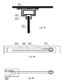
- Figs. 4A - 4C depict a guide mechanism with a stop of the sliding member according to the present invention.
- the elongated guide (203) is fixedly mounted, and supported along its length, on the bottom side of the bonnet (102).
- a sliding member (202) is provided to slide along the length of the elongated guide (203).
- the sliding member (202) slidably moves within the elongated guide (203).
- the mechanism for prevention of sliding back 205 may have a form of one or more locking elements that allow only one direction movement such as a locking pawl.
- the mechanism for prevention of sliding back 205 is shown in its disabled state in Fig. 4B and in its enabled state in Fig. 4C .
Landscapes
- Engineering & Computer Science (AREA)
- Mechanical Engineering (AREA)
- Chemical & Material Sciences (AREA)
- Combustion & Propulsion (AREA)
- Transportation (AREA)
- Superstructure Of Vehicle (AREA)
Abstract
Description
- The present invention relates to vehicle bonnet safety assembly, in particular for typical cars.
- The present technical concept addresses situations where a vehicle bonnet flips over the windscreen during an accidental opening or traffic accident. As it appears, despite typical latch mechanisms provided by vehicle manufacturers in the front-middle section of a bonnet, accidental bonnet opening happens in practice. Hence, what is required is a means to address safety issues during an accident when the first locking means fails.
- Bonnet safety assembly must thus address two major concerns that are first to prevent opening of the bonnet and second, if the opening is unavoidable, to provide means allowing for such opening of the bonnet that will not result in the driver's line of sight being blocked by the opened bonnet.
- A prior art publication
US2333467A entitled "Hood control for motor cars" discloses a latching mechanism wherein the hood is locked down at four points. When the car arrives at the filling station for service, the driver releases the hood by actuation of lever. - The '467 publication does not address the safety issues during an accident when the first locking means fails.
- Another prior art publication
US3905624A entitled "Hood latching device for automotive vehicles" discloses that if a spring urging the hooked latch member toward the closed position happens to be broken at that time as a result of fatigue or the like, there will still be a possibility of the hood cover being fly-opened under the action of another spring provided in the first latch mechanism or the action of a rubber damper provided on the vehicle body as the first latch mechanism is released. Since the opening of the hood cover deprives the driver of forward visibility almost entirely, such an accident is extremely dangerous particularly when the vehicle is being driven at a high speed. - Therefore '624 provides a hood latching device comprising a first latch mechanism and a second latch member having a hooked member whereby the above described drawback of the conventional latching device is substantially eliminated by an improved hood latching device wherein the releasing movement of the hooked member of the second latching mechanism is prevented by a member cooperating with the first latching mechanism, and the possibility of accidental release of the second latch mechanism is thereby substantially eliminated.
- The disadvantage of the known solution is that in some cases the arrangement is insufficient to hold the bonnet that may flip onto the windscreen thereby obscuring visibility for a driver.
- It would be thus desirable to provide an improved vehicle bonnet safety assembly. Preferably such method and system shall improved protection and in case of failure allow visibility of the road for a driver.
- The object of the present invention is a vehicle bonnet safety assembly, the vehicle comprising: a bonnet; a windscreen; a chassis, to which the bonnet is hingedly joined by means of actuators; the assembly further comprises: an elongated guide fixedly mounted, and supported along its length, on the bottom side of the bonnet; a sliding member provided inside the elongated guide to slide along the length of the elongated guide until it engages a stop coupled to the elongated guide; whereas the sliding member is mounted in the elongated guide such that it is prevented from sliding out and sliding back the elongated guide thereby creating a field of visibility on the road for a driver when the bonnet flips over the windscreen.
- Preferably, the actuators are mounted such that they are prevented from detaching from the sliding member.
- Preferably, the actuators are pneumatic actuators wherein in each actuator a pneumatic valve allows the flow of a medium when the bonnet is being opened with a force below a threshold and prevents the flow of a medium when the bonnet is being opened with a force above a threshold.
- Preferably, the mechanism for prevention of sliding back has a form of one or more locking elements that allow only one direction movement.
- Preferably, the mechanism for prevention of sliding back comprises at least one locking pawl.
- The present invention is shown by means of exemplary embodiments on a drawing, in which:
-
Fig. 1 presents a schematic diagram of an assembly according to the present invention; -
Figs. 2A - 2B present a schematic diagram of an enhancement of the assembly according to the present invention; -
Fig. 3 depicts an actuator of the assembly according to the present invention; -
Figs. 4A - 4C depict a guide mechanism with a stop of the sliding member according to the present invention; - In a moving vehicle, any object on or in the vehicle has its own inertia. In case of an accident the inertia forces of different objects of the above are independent. The vehicle may be brought to an abrupt stop while its bonnet, thrown in an opposite direction, may flip over the vehicle's windscreen thereby obscuring the view on the road.
- In
Fig. 1 there is shown a car's (101) bonnet (105, 106) restraining mechanism, which includes a retractable strap (106) which is secured to a retraction mechanism (105) further secured to the car's chassis (107) or frame at one end and is secured to the car's bonnet (102) at an opposite end. - The bonnet (102) is also hingedly joined with the chassis of the vehicle in order to provide normal opening function.
- The restraining mechanism at the car's chassis or frame end comprises the retraction mechanism (105) coupled to an inertia reel in the present embodiment located in the area typical for a headlight (the location may differ and the inertia reel may be mounted on (fastened to) the left of right side of the vehicle or at the front of the vehicle). The inertia reel mechanism may be such as the one disclosed in "Inertia reel mechanisms" -
US 3578260 A or "Inertia locking retractor" -US 3917189 A or similar, allowing for a strap or belt to be automatically locked against extension when the bonnet rapidly moves relative to the vehicle's engine compartment with an acceleration above a predetermined acceleration. - Such strap has the ability to extend and retract. The bonnet (102) may be opened easily when the strap is extended with a low to moderate force below a predetermined threshold, but in case a strong force is applied, above the predefined threshold, the strap will instantly tighten up and hold the bonnet secured in place (i.e in proximity to the engine compartment) and preventing it from flipping onto the windscreen (104).
- In other words, the retractable strap (106) is allowed to extend in case a force below a predetermined threshold is applied and retractable strap (106) is prevented from extending when a force above the predefined threshold is applied.
- There may be installed one or two bonnet restraining mechanism on the left and right side of the bonnet (102) accordingly.
- It is also to be noted that the strap has to have suitable strength to hold the opening bonnet when the bonnet rapidly accelerates and subsequently decelerates. Nevertheless, different materials and different width and/or thickness of the strap may be applied.
-
Fig. 2A presents a schematic diagram of an enhancement of the assembly according to the present invention. The enhancement is to ensure driver's visibility of the road in case bonnet opening prevention mechanisms have failed. - The car's (101) bonnet (102) may be opened and subsequently supported with two actuators (201) such as pneumatic actuators. There are typically two of such actuators (201), positioned on the left and right side of the bonnet (102), connecting the bonnet (102) with the chassis.
- The present invention introduces a mechanism between the top end of the actuator (201) and the bonnet (102). The mechanism includes an elongated guide (203) fixedly mounted, and supported along its length, on the bottom side of the bonnet (102). A sliding member (202) is provided inside the elongated guide (203) to slide along the length of the elongated guide (203) until it engages a stop (shown in details in
Figs. 4B-4C ) coupled to the elongated guide (203). The sliding member (202) is mounted in the elongated guide (203) such that it will never slide out of the elongated guide (203) (the sliding member is prevented from sliding out of the elongated guide). - Once the sliding member (202) reaches the stop, it will be prevented from sliding back the elongated guide (203), thereby creating a field of visibility on the road for the driver as shown in
Fig. 2B , when the bonnet flips over the windscreen. The mechanism for prevention of sliding back may have a form of a latch. - The obtained field of visibility may be different depending on the length of the applied sliding member (202) and the elongated guide (203).
- Accordingly, the actuators (201) are mounted such that they will never detach from the sliding member (202) (they are prevented from detaching from the sliding member (202) by means of for example screws).
-
Fig. 3 depicts an actuator of the assembly according to the present invention. A hydraulic or pneumatic actuator (201) is attached to the bonnet (102). The pneumatic actuator arrangement is shown inFig. 3 schematically by means of the two triangles (204). A pneumatic valve limits a flow of a medium when the bonnet (102) is being opened with a normal speed and does not cause excessive hindrance on opening. - However, when the bonnet (102) is opened rapidly, the valve will close the flow of the medium in a piston thereby disabling the possibility of opening the bonnet (102).
- In other words, in each actuator (201) a pneumatic valve allows the flow of a medium when the bonnet (102) is being opened with a force below a threshold and prevents the flow of a medium when the bonnet (102) is being opened with a force above a threshold.
- The valve may be external or internal (inside the piston). Optionally the pistons may be equipped with a safety valves disabling opening of the bonnet (102).
-
Figs. 4A - 4C depict a guide mechanism with a stop of the sliding member according to the present invention. The elongated guide (203) is fixedly mounted, and supported along its length, on the bottom side of the bonnet (102). A sliding member (202) is provided to slide along the length of the elongated guide (203). The sliding member (202) slidably moves within the elongated guide (203). - The mechanism for prevention of sliding back 205 may have a form of one or more locking elements that allow only one direction movement such as a locking pawl. The mechanism for prevention of sliding back 205 is shown in its disabled state in
Fig. 4B and in its enabled state inFig. 4C . - While the invention presented herein has been depicted, described, and has been defined with reference to particular preferred embodiments, such references and examples of implementation in the foregoing specification do not imply any limitation on the invention. It will, however, be evident that various modifications and changes may be made thereto without departing from the broader scope of the technical concept. The presented preferred embodiments are exemplary only, and are not exhaustive of the scope of the technical concept presented herein.
- Accordingly, the scope of protection is not limited to the preferred embodiments described in the specification, but is only limited by the claims that follow.
- In addition, any combination of the appended claims in envisaged in the present application.
Claims (5)
- A vehicle bonnet safety assembly, the vehicle comprising:○ a bonnet (102);○ a windscreen;○ a chassis (107), to which the bonnet (102) is hingedly joined by means of actuators (201);the assembly being characterized in that it comprises:○ an elongated guide (203) fixedly mounted, and supported along its length, on the bottom side of the bonnet (102);○ a sliding member (202) provided inside the elongated guide (203) to slide along the length of the elongated guide (203) until it engages a stop coupled to the elongated guide (203);○ whereas the sliding member (202) is mounted in the elongated guide (203) such that it is prevented from sliding out and sliding back the elongated guide (203) thereby creating a field of visibility on the road for a driver when the bonnet flips over the windscreen.
- The assembly according to claim 1, characterized in that the actuators (201) are mounted such that they are prevented from detaching from the sliding member (202).
- The assembly according to claim 2, characterized in that the actuators (201) are pneumatic actuators wherein in each actuator (201) a pneumatic valve allows the flow of a medium when the bonnet (102) is being opened with a force below a threshold and prevents the flow of a medium when the bonnet (102) is being opened with a force above a threshold.
- The assembly according to claim 1, characterized in that the mechanism for prevention of sliding back (205) has a form of one or more locking elements that allow only one direction movement.
- The assembly according to claim 4, characterized in that the mechanism for prevention of sliding back (205) comprises at least one locking pawl.
Priority Applications (3)
| Application Number | Priority Date | Filing Date | Title |
|---|---|---|---|
| EP13189457.8A EP2862755B1 (en) | 2013-10-21 | 2013-10-21 | Vehicle bonnet safety assembly |
| CN201410557679.4A CN104554471B (en) | 2013-10-21 | 2014-10-20 | Vehicle with bonnet safety assembly |
| US14/517,969 US9156502B2 (en) | 2013-10-21 | 2014-10-20 | Vehicle bonnet safety assembly |
Applications Claiming Priority (1)
| Application Number | Priority Date | Filing Date | Title |
|---|---|---|---|
| EP13189457.8A EP2862755B1 (en) | 2013-10-21 | 2013-10-21 | Vehicle bonnet safety assembly |
Publications (2)
| Publication Number | Publication Date |
|---|---|
| EP2862755A1 true EP2862755A1 (en) | 2015-04-22 |
| EP2862755B1 EP2862755B1 (en) | 2016-06-08 |
Family
ID=49484107
Family Applications (1)
| Application Number | Title | Priority Date | Filing Date |
|---|---|---|---|
| EP13189457.8A Not-in-force EP2862755B1 (en) | 2013-10-21 | 2013-10-21 | Vehicle bonnet safety assembly |
Country Status (3)
| Country | Link |
|---|---|
| US (1) | US9156502B2 (en) |
| EP (1) | EP2862755B1 (en) |
| CN (1) | CN104554471B (en) |
Families Citing this family (7)
| Publication number | Priority date | Publication date | Assignee | Title |
|---|---|---|---|---|
| EP2862786A1 (en) * | 2013-10-21 | 2015-04-22 | Advanced Digital Broadcast S.A. | Vehicle bonnet safety assembly |
| EP3208148B1 (en) * | 2016-02-19 | 2018-08-01 | U-Shin Deutschland Zugangssysteme GmbH | Spindle drive for a motor vehicle |
| CN106800046A (en) * | 2016-12-14 | 2017-06-06 | 无锡市盛源汽车配件厂 | The automobile engine cover of drafting tool is installed |
| CN106627783A (en) * | 2016-12-16 | 2017-05-10 | 无锡市盛源汽车配件厂 | Automobile engine cover with traction auxiliary function |
| CN106627781A (en) * | 2016-12-16 | 2017-05-10 | 无锡市盛源汽车配件厂 | Automobile engine hood with cooling function |
| US10669757B2 (en) | 2017-11-30 | 2020-06-02 | Fca Us Llc | Variable position vehicle hood stay device |
| CN110104073B (en) * | 2019-05-07 | 2020-12-04 | 绍兴不忘初心机械设计有限公司 | An anti-lifting car hood |
Citations (6)
| Publication number | Priority date | Publication date | Assignee | Title |
|---|---|---|---|---|
| US2333467A (en) | 1941-03-31 | 1943-11-02 | Bassick Co | Hood control for motor cars |
| US3578260A (en) | 1968-06-27 | 1971-05-11 | Kangel Magnet Ltd | Inertia reel mechanisms |
| US3905624A (en) | 1973-11-30 | 1975-09-16 | Aisin Seiki | Hood latching device for automotive vehicles |
| US3917189A (en) | 1972-05-26 | 1975-11-04 | Gateway Industries | Inertia locking retractor |
| US4946002A (en) * | 1989-03-30 | 1990-08-07 | Vu Thuan D | Hood bumper protector |
| WO2010070303A1 (en) * | 2008-12-16 | 2010-06-24 | Autoliv Development Ab | A safety arrangement |
Family Cites Families (12)
| Publication number | Priority date | Publication date | Assignee | Title |
|---|---|---|---|---|
| CN2128227Y (en) * | 1992-05-30 | 1993-03-17 | 王洪强 | Bonnet safety device for automobile |
| FR2813848B1 (en) * | 2000-09-13 | 2003-02-14 | Peguform France | MOTOR VEHICLE COMPRISING BODY PARTS ASSOCIATED WITH A REDUCED GAME |
| DE60226138T2 (en) * | 2002-09-20 | 2009-05-28 | Ford Global Technologies, LLC, Dearborn | Safety device for pedestrians |
| JP4160848B2 (en) * | 2003-03-20 | 2008-10-08 | 本田技研工業株式会社 | Collision protection device for vehicle |
| US6991055B2 (en) * | 2003-07-01 | 2006-01-31 | General Motors Corporation | Motorized cover system and method of use thereof |
| GB2410924B (en) * | 2004-02-14 | 2007-04-11 | Ford Global Tech Llc | A hinge arrangement |
| US7334656B2 (en) * | 2004-05-25 | 2008-02-26 | Gm Global Technology Operations, Inc. | Hood elevation system |
| EP1736380B1 (en) * | 2005-06-23 | 2008-07-09 | Mazda Motor Corporation | A safety device of a vehicle and a vehicle provided therewith |
| JP4410822B2 (en) * | 2008-01-25 | 2010-02-03 | トヨタ自動車株式会社 | Pop-up hood device for vehicle |
| JP4601700B2 (en) * | 2008-02-01 | 2010-12-22 | 豊田合成株式会社 | Hood flip-up device |
| JP4514813B2 (en) * | 2008-06-04 | 2010-07-28 | 太平洋工業株式会社 | Bonnet shock absorber |
| EP2733024B1 (en) * | 2012-11-15 | 2016-04-06 | Volvo Car Corporation | A safety arrangement for a vehicle |
-
2013
- 2013-10-21 EP EP13189457.8A patent/EP2862755B1/en not_active Not-in-force
-
2014
- 2014-10-20 US US14/517,969 patent/US9156502B2/en not_active Expired - Fee Related
- 2014-10-20 CN CN201410557679.4A patent/CN104554471B/en not_active Expired - Fee Related
Patent Citations (6)
| Publication number | Priority date | Publication date | Assignee | Title |
|---|---|---|---|---|
| US2333467A (en) | 1941-03-31 | 1943-11-02 | Bassick Co | Hood control for motor cars |
| US3578260A (en) | 1968-06-27 | 1971-05-11 | Kangel Magnet Ltd | Inertia reel mechanisms |
| US3917189A (en) | 1972-05-26 | 1975-11-04 | Gateway Industries | Inertia locking retractor |
| US3905624A (en) | 1973-11-30 | 1975-09-16 | Aisin Seiki | Hood latching device for automotive vehicles |
| US4946002A (en) * | 1989-03-30 | 1990-08-07 | Vu Thuan D | Hood bumper protector |
| WO2010070303A1 (en) * | 2008-12-16 | 2010-06-24 | Autoliv Development Ab | A safety arrangement |
Also Published As
| Publication number | Publication date |
|---|---|
| US9156502B2 (en) | 2015-10-13 |
| CN104554471A (en) | 2015-04-29 |
| EP2862755B1 (en) | 2016-06-08 |
| US20150107926A1 (en) | 2015-04-23 |
| CN104554471B (en) | 2017-04-12 |
Similar Documents
| Publication | Publication Date | Title |
|---|---|---|
| US9156502B2 (en) | Vehicle bonnet safety assembly | |
| EP2902272B1 (en) | Hood latch assembly | |
| US7575273B2 (en) | Bonnet bumpstop for a vehicle | |
| JP6469257B2 (en) | Automotive hinge for pedestrian protection and its deployment method | |
| US10336291B2 (en) | Motor vehicle comprising a front gate which is arranged pivotably on a body via two hinge joints | |
| CN108116654B (en) | Rotary wing aircraft with sliding members, especially sliding doors or windows | |
| US10232818B2 (en) | Motor vehicle with pedestrian airbag | |
| US20180044954A1 (en) | Closure Bracket Assembly for Selectively Retaining or Rotationally Releasing an Engine Hood of a Motor Vehicle | |
| US9457762B2 (en) | Active hood front cover for pedestrian protection | |
| US20140319857A1 (en) | Door structure having a locking element that inhibits the door release | |
| US9221418B1 (en) | Hinged mounting system for airbag module having deployable lock | |
| EP2862786A1 (en) | Vehicle bonnet safety assembly | |
| US8870225B2 (en) | Safety device for vehicle | |
| CN112272623B (en) | Cover components for vehicle roofs and roofs for motor vehicles | |
| EP2181020B1 (en) | Vehicle seat with a stowable head restraint and an anti-whiplash system | |
| KR20170025659A (en) | A passive hood latch structure for cars | |
| CN107054441B (en) | Steering column with split J-block | |
| EP3184376B1 (en) | Hinge arrangement | |
| KR101047929B1 (en) | Vehicle protection | |
| KR101157733B1 (en) | Bracket having key-hole shape | |
| WO2022236940A1 (en) | Vehicle occupant protection system | |
| KR101023853B1 (en) | Automotive airbag door device to prevent collision with windshield glass | |
| GB2375332A (en) | Wheel restraint system | |
| GB2411866A (en) | A pedestrian safety device | |
| DE102011010848A1 (en) | Vehicle has vehicle structure and attached part fastened to vehicle structure by fastening element, where safety arrangement is provided for redundant fastening of attached part to vehicle structure |
Legal Events
| Date | Code | Title | Description |
|---|---|---|---|
| PUAI | Public reference made under article 153(3) epc to a published international application that has entered the european phase |
Free format text: ORIGINAL CODE: 0009012 |
|
| 17P | Request for examination filed |
Effective date: 20131021 |
|
| AK | Designated contracting states |
Kind code of ref document: A1 Designated state(s): AL AT BE BG CH CY CZ DE DK EE ES FI FR GB GR HR HU IE IS IT LI LT LU LV MC MK MT NL NO PL PT RO RS SE SI SK SM TR |
|
| AX | Request for extension of the european patent |
Extension state: BA ME |
|
| R17P | Request for examination filed (corrected) |
Effective date: 20150518 |
|
| RBV | Designated contracting states (corrected) |
Designated state(s): AL AT BE BG CH CY CZ DE DK EE ES FI FR GB GR HR HU IE IS IT LI LT LU LV MC MK MT NL NO PL PT RO RS SE SI SK SM TR |
|
| RIC1 | Information provided on ipc code assigned before grant |
Ipc: B60R 21/38 20110101AFI20150608BHEP Ipc: B62D 25/10 20060101ALI20150608BHEP Ipc: B62D 25/12 20060101ALI20150608BHEP Ipc: B60R 22/00 20060101ALI20150608BHEP Ipc: E05C 17/00 20060101ALI20150608BHEP |
|
| 17Q | First examination report despatched |
Effective date: 20151021 |
|
| GRAP | Despatch of communication of intention to grant a patent |
Free format text: ORIGINAL CODE: EPIDOSNIGR1 |
|
| GRAP | Despatch of communication of intention to grant a patent |
Free format text: ORIGINAL CODE: EPIDOSNIGR1 |
|
| RIC1 | Information provided on ipc code assigned before grant |
Ipc: B60R 21/38 20110101AFI20160210BHEP Ipc: E05C 17/60 20060101ALI20160210BHEP Ipc: B62D 25/12 20060101ALI20160210BHEP |
|
| INTG | Intention to grant announced |
Effective date: 20160304 |
|
| INTG | Intention to grant announced |
Effective date: 20160315 |
|
| GRAS | Grant fee paid |
Free format text: ORIGINAL CODE: EPIDOSNIGR3 |
|
| GRAA | (expected) grant |
Free format text: ORIGINAL CODE: 0009210 |
|
| AK | Designated contracting states |
Kind code of ref document: B1 Designated state(s): AL AT BE BG CH CY CZ DE DK EE ES FI FR GB GR HR HU IE IS IT LI LT LU LV MC MK MT NL NO PL PT RO RS SE SI SK SM TR |
|
| REG | Reference to a national code |
Ref country code: GB Ref legal event code: FG4D |
|
| REG | Reference to a national code |
Ref country code: CH Ref legal event code: EP |
|
| REG | Reference to a national code |
Ref country code: IE Ref legal event code: FG4D |
|
| REG | Reference to a national code |
Ref country code: AT Ref legal event code: REF Ref document number: 804975 Country of ref document: AT Kind code of ref document: T Effective date: 20160715 |
|
| REG | Reference to a national code |
Ref country code: DE Ref legal event code: R096 Ref document number: 602013008346 Country of ref document: DE |
|
| REG | Reference to a national code |
Ref country code: LT Ref legal event code: MG4D |
|
| REG | Reference to a national code |
Ref country code: NL Ref legal event code: MP Effective date: 20160608 |
|
| REG | Reference to a national code |
Ref country code: FR Ref legal event code: PLFP Year of fee payment: 4 |
|
| PG25 | Lapsed in a contracting state [announced via postgrant information from national office to epo] |
Ref country code: LT Free format text: LAPSE BECAUSE OF FAILURE TO SUBMIT A TRANSLATION OF THE DESCRIPTION OR TO PAY THE FEE WITHIN THE PRESCRIBED TIME-LIMIT Effective date: 20160608 Ref country code: FI Free format text: LAPSE BECAUSE OF FAILURE TO SUBMIT A TRANSLATION OF THE DESCRIPTION OR TO PAY THE FEE WITHIN THE PRESCRIBED TIME-LIMIT Effective date: 20160608 Ref country code: NO Free format text: LAPSE BECAUSE OF FAILURE TO SUBMIT A TRANSLATION OF THE DESCRIPTION OR TO PAY THE FEE WITHIN THE PRESCRIBED TIME-LIMIT Effective date: 20160908 |
|
| REG | Reference to a national code |
Ref country code: AT Ref legal event code: MK05 Ref document number: 804975 Country of ref document: AT Kind code of ref document: T Effective date: 20160608 |
|
| PG25 | Lapsed in a contracting state [announced via postgrant information from national office to epo] |
Ref country code: ES Free format text: LAPSE BECAUSE OF FAILURE TO SUBMIT A TRANSLATION OF THE DESCRIPTION OR TO PAY THE FEE WITHIN THE PRESCRIBED TIME-LIMIT Effective date: 20160608 Ref country code: RS Free format text: LAPSE BECAUSE OF FAILURE TO SUBMIT A TRANSLATION OF THE DESCRIPTION OR TO PAY THE FEE WITHIN THE PRESCRIBED TIME-LIMIT Effective date: 20160608 Ref country code: HR Free format text: LAPSE BECAUSE OF FAILURE TO SUBMIT A TRANSLATION OF THE DESCRIPTION OR TO PAY THE FEE WITHIN THE PRESCRIBED TIME-LIMIT Effective date: 20160608 Ref country code: NL Free format text: LAPSE BECAUSE OF FAILURE TO SUBMIT A TRANSLATION OF THE DESCRIPTION OR TO PAY THE FEE WITHIN THE PRESCRIBED TIME-LIMIT Effective date: 20160608 Ref country code: LV Free format text: LAPSE BECAUSE OF FAILURE TO SUBMIT A TRANSLATION OF THE DESCRIPTION OR TO PAY THE FEE WITHIN THE PRESCRIBED TIME-LIMIT Effective date: 20160608 Ref country code: GR Free format text: LAPSE BECAUSE OF FAILURE TO SUBMIT A TRANSLATION OF THE DESCRIPTION OR TO PAY THE FEE WITHIN THE PRESCRIBED TIME-LIMIT Effective date: 20160909 Ref country code: SE Free format text: LAPSE BECAUSE OF FAILURE TO SUBMIT A TRANSLATION OF THE DESCRIPTION OR TO PAY THE FEE WITHIN THE PRESCRIBED TIME-LIMIT Effective date: 20160608 |
|
| PG25 | Lapsed in a contracting state [announced via postgrant information from national office to epo] |
Ref country code: IS Free format text: LAPSE BECAUSE OF FAILURE TO SUBMIT A TRANSLATION OF THE DESCRIPTION OR TO PAY THE FEE WITHIN THE PRESCRIBED TIME-LIMIT Effective date: 20161008 Ref country code: EE Free format text: LAPSE BECAUSE OF FAILURE TO SUBMIT A TRANSLATION OF THE DESCRIPTION OR TO PAY THE FEE WITHIN THE PRESCRIBED TIME-LIMIT Effective date: 20160608 Ref country code: SK Free format text: LAPSE BECAUSE OF FAILURE TO SUBMIT A TRANSLATION OF THE DESCRIPTION OR TO PAY THE FEE WITHIN THE PRESCRIBED TIME-LIMIT Effective date: 20160608 Ref country code: RO Free format text: LAPSE BECAUSE OF FAILURE TO SUBMIT A TRANSLATION OF THE DESCRIPTION OR TO PAY THE FEE WITHIN THE PRESCRIBED TIME-LIMIT Effective date: 20160608 Ref country code: CZ Free format text: LAPSE BECAUSE OF FAILURE TO SUBMIT A TRANSLATION OF THE DESCRIPTION OR TO PAY THE FEE WITHIN THE PRESCRIBED TIME-LIMIT Effective date: 20160608 Ref country code: IT Free format text: LAPSE BECAUSE OF FAILURE TO SUBMIT A TRANSLATION OF THE DESCRIPTION OR TO PAY THE FEE WITHIN THE PRESCRIBED TIME-LIMIT Effective date: 20160608 |
|
| PG25 | Lapsed in a contracting state [announced via postgrant information from national office to epo] |
Ref country code: PT Free format text: LAPSE BECAUSE OF FAILURE TO SUBMIT A TRANSLATION OF THE DESCRIPTION OR TO PAY THE FEE WITHIN THE PRESCRIBED TIME-LIMIT Effective date: 20161010 Ref country code: AT Free format text: LAPSE BECAUSE OF FAILURE TO SUBMIT A TRANSLATION OF THE DESCRIPTION OR TO PAY THE FEE WITHIN THE PRESCRIBED TIME-LIMIT Effective date: 20160608 Ref country code: PL Free format text: LAPSE BECAUSE OF FAILURE TO SUBMIT A TRANSLATION OF THE DESCRIPTION OR TO PAY THE FEE WITHIN THE PRESCRIBED TIME-LIMIT Effective date: 20160608 Ref country code: BE Free format text: LAPSE BECAUSE OF NON-PAYMENT OF DUE FEES Effective date: 20160608 Ref country code: SM Free format text: LAPSE BECAUSE OF FAILURE TO SUBMIT A TRANSLATION OF THE DESCRIPTION OR TO PAY THE FEE WITHIN THE PRESCRIBED TIME-LIMIT Effective date: 20160608 |
|
| REG | Reference to a national code |
Ref country code: DE Ref legal event code: R097 Ref document number: 602013008346 Country of ref document: DE |
|
| PLBE | No opposition filed within time limit |
Free format text: ORIGINAL CODE: 0009261 |
|
| STAA | Information on the status of an ep patent application or granted ep patent |
Free format text: STATUS: NO OPPOSITION FILED WITHIN TIME LIMIT |
|
| 26N | No opposition filed |
Effective date: 20170309 |
|
| PG25 | Lapsed in a contracting state [announced via postgrant information from national office to epo] |
Ref country code: SI Free format text: LAPSE BECAUSE OF FAILURE TO SUBMIT A TRANSLATION OF THE DESCRIPTION OR TO PAY THE FEE WITHIN THE PRESCRIBED TIME-LIMIT Effective date: 20160608 Ref country code: DK Free format text: LAPSE BECAUSE OF FAILURE TO SUBMIT A TRANSLATION OF THE DESCRIPTION OR TO PAY THE FEE WITHIN THE PRESCRIBED TIME-LIMIT Effective date: 20160608 |
|
| REG | Reference to a national code |
Ref country code: CH Ref legal event code: PL |
|
| REG | Reference to a national code |
Ref country code: IE Ref legal event code: MM4A |
|
| PG25 | Lapsed in a contracting state [announced via postgrant information from national office to epo] |
Ref country code: CH Free format text: LAPSE BECAUSE OF NON-PAYMENT OF DUE FEES Effective date: 20161031 Ref country code: LI Free format text: LAPSE BECAUSE OF NON-PAYMENT OF DUE FEES Effective date: 20161031 |
|
| PG25 | Lapsed in a contracting state [announced via postgrant information from national office to epo] |
Ref country code: LU Free format text: LAPSE BECAUSE OF NON-PAYMENT OF DUE FEES Effective date: 20161021 |
|
| REG | Reference to a national code |
Ref country code: FR Ref legal event code: PLFP Year of fee payment: 5 |
|
| PG25 | Lapsed in a contracting state [announced via postgrant information from national office to epo] |
Ref country code: IE Free format text: LAPSE BECAUSE OF NON-PAYMENT OF DUE FEES Effective date: 20161021 |
|
| PG25 | Lapsed in a contracting state [announced via postgrant information from national office to epo] |
Ref country code: HU Free format text: LAPSE BECAUSE OF FAILURE TO SUBMIT A TRANSLATION OF THE DESCRIPTION OR TO PAY THE FEE WITHIN THE PRESCRIBED TIME-LIMIT; INVALID AB INITIO Effective date: 20131021 |
|
| PG25 | Lapsed in a contracting state [announced via postgrant information from national office to epo] |
Ref country code: CY Free format text: LAPSE BECAUSE OF FAILURE TO SUBMIT A TRANSLATION OF THE DESCRIPTION OR TO PAY THE FEE WITHIN THE PRESCRIBED TIME-LIMIT Effective date: 20160608 Ref country code: MK Free format text: LAPSE BECAUSE OF FAILURE TO SUBMIT A TRANSLATION OF THE DESCRIPTION OR TO PAY THE FEE WITHIN THE PRESCRIBED TIME-LIMIT Effective date: 20160608 Ref country code: MC Free format text: LAPSE BECAUSE OF FAILURE TO SUBMIT A TRANSLATION OF THE DESCRIPTION OR TO PAY THE FEE WITHIN THE PRESCRIBED TIME-LIMIT Effective date: 20160608 Ref country code: MT Free format text: LAPSE BECAUSE OF NON-PAYMENT OF DUE FEES Effective date: 20161031 |
|
| PG25 | Lapsed in a contracting state [announced via postgrant information from national office to epo] |
Ref country code: BG Free format text: LAPSE BECAUSE OF FAILURE TO SUBMIT A TRANSLATION OF THE DESCRIPTION OR TO PAY THE FEE WITHIN THE PRESCRIBED TIME-LIMIT Effective date: 20160608 |
|
| REG | Reference to a national code |
Ref country code: FR Ref legal event code: PLFP Year of fee payment: 6 |
|
| PG25 | Lapsed in a contracting state [announced via postgrant information from national office to epo] |
Ref country code: TR Free format text: LAPSE BECAUSE OF FAILURE TO SUBMIT A TRANSLATION OF THE DESCRIPTION OR TO PAY THE FEE WITHIN THE PRESCRIBED TIME-LIMIT Effective date: 20160608 Ref country code: AL Free format text: LAPSE BECAUSE OF FAILURE TO SUBMIT A TRANSLATION OF THE DESCRIPTION OR TO PAY THE FEE WITHIN THE PRESCRIBED TIME-LIMIT Effective date: 20160608 |
|
| PGFP | Annual fee paid to national office [announced via postgrant information from national office to epo] |
Ref country code: DE Payment date: 20181029 Year of fee payment: 6 |
|
| PGFP | Annual fee paid to national office [announced via postgrant information from national office to epo] |
Ref country code: GB Payment date: 20181029 Year of fee payment: 6 Ref country code: FR Payment date: 20181025 Year of fee payment: 6 |
|
| REG | Reference to a national code |
Ref country code: DE Ref legal event code: R119 Ref document number: 602013008346 Country of ref document: DE |
|
| PG25 | Lapsed in a contracting state [announced via postgrant information from national office to epo] |
Ref country code: DE Free format text: LAPSE BECAUSE OF NON-PAYMENT OF DUE FEES Effective date: 20200501 |
|
| GBPC | Gb: european patent ceased through non-payment of renewal fee |
Effective date: 20191021 |
|
| PG25 | Lapsed in a contracting state [announced via postgrant information from national office to epo] |
Ref country code: GB Free format text: LAPSE BECAUSE OF NON-PAYMENT OF DUE FEES Effective date: 20191021 Ref country code: FR Free format text: LAPSE BECAUSE OF NON-PAYMENT OF DUE FEES Effective date: 20191031 |