EP2862614B2 - Filter system with filter element - Google Patents
Filter system with filter element Download PDFInfo
- Publication number
- EP2862614B2 EP2862614B2 EP14182486.2A EP14182486A EP2862614B2 EP 2862614 B2 EP2862614 B2 EP 2862614B2 EP 14182486 A EP14182486 A EP 14182486A EP 2862614 B2 EP2862614 B2 EP 2862614B2
- Authority
- EP
- European Patent Office
- Prior art keywords
- filter
- housing
- folds
- secondary element
- filter medium
- Prior art date
- Legal status (The legal status is an assumption and is not a legal conclusion. Google has not performed a legal analysis and makes no representation as to the accuracy of the status listed.)
- Active
Links
- 239000000428 dust Substances 0.000 claims description 22
- 239000012530 fluid Substances 0.000 claims description 19
- 239000002245 particle Substances 0.000 claims description 14
- 238000002485 combustion reaction Methods 0.000 claims description 7
- 238000007599 discharging Methods 0.000 claims description 3
- 239000004745 nonwoven fabric Substances 0.000 claims 1
- 238000009434 installation Methods 0.000 description 10
- 238000000926 separation method Methods 0.000 description 7
- 230000002349 favourable effect Effects 0.000 description 6
- 229920002678 cellulose Polymers 0.000 description 4
- 239000001913 cellulose Substances 0.000 description 4
- 238000010276 construction Methods 0.000 description 4
- 238000011109 contamination Methods 0.000 description 4
- 239000004033 plastic Substances 0.000 description 4
- 229920003023 plastic Polymers 0.000 description 4
- 238000007789 sealing Methods 0.000 description 4
- 230000007423 decrease Effects 0.000 description 2
- 239000000835 fiber Substances 0.000 description 2
- 239000000463 material Substances 0.000 description 2
- 229920005830 Polyurethane Foam Polymers 0.000 description 1
- 239000011248 coating agent Substances 0.000 description 1
- 238000000576 coating method Methods 0.000 description 1
- 239000012141 concentrate Substances 0.000 description 1
- 230000000694 effects Effects 0.000 description 1
- 229920001971 elastomer Polymers 0.000 description 1
- 239000000806 elastomer Substances 0.000 description 1
- 238000004049 embossing Methods 0.000 description 1
- 230000007613 environmental effect Effects 0.000 description 1
- 230000005484 gravity Effects 0.000 description 1
- 238000005470 impregnation Methods 0.000 description 1
- 238000004519 manufacturing process Methods 0.000 description 1
- 239000002184 metal Substances 0.000 description 1
- 239000002121 nanofiber Substances 0.000 description 1
- 238000012856 packing Methods 0.000 description 1
- 230000000149 penetrating effect Effects 0.000 description 1
- 239000011496 polyurethane foam Substances 0.000 description 1
- 230000000284 resting effect Effects 0.000 description 1
- 230000035939 shock Effects 0.000 description 1
- 238000004804 winding Methods 0.000 description 1
Images


Classifications
-
- B—PERFORMING OPERATIONS; TRANSPORTING
- B01—PHYSICAL OR CHEMICAL PROCESSES OR APPARATUS IN GENERAL
- B01D—SEPARATION
- B01D46/00—Filters or filtering processes specially modified for separating dispersed particles from gases or vapours
- B01D46/52—Particle separators, e.g. dust precipitators, using filters embodying folded corrugated or wound sheet material
- B01D46/521—Particle separators, e.g. dust precipitators, using filters embodying folded corrugated or wound sheet material using folded, pleated material
- B01D46/522—Particle separators, e.g. dust precipitators, using filters embodying folded corrugated or wound sheet material using folded, pleated material with specific folds, e.g. having different lengths
-
- B—PERFORMING OPERATIONS; TRANSPORTING
- B01—PHYSICAL OR CHEMICAL PROCESSES OR APPARATUS IN GENERAL
- B01D—SEPARATION
- B01D39/00—Filtering material for liquid or gaseous fluids
- B01D39/14—Other self-supporting filtering material ; Other filtering material
- B01D39/16—Other self-supporting filtering material ; Other filtering material of organic material, e.g. synthetic fibres
- B01D39/18—Other self-supporting filtering material ; Other filtering material of organic material, e.g. synthetic fibres the material being cellulose or derivatives thereof
-
- B—PERFORMING OPERATIONS; TRANSPORTING
- B01—PHYSICAL OR CHEMICAL PROCESSES OR APPARATUS IN GENERAL
- B01D—SEPARATION
- B01D46/00—Filters or filtering processes specially modified for separating dispersed particles from gases or vapours
- B01D46/24—Particle separators, e.g. dust precipitators, using rigid hollow filter bodies
- B01D46/2403—Particle separators, e.g. dust precipitators, using rigid hollow filter bodies characterised by the physical shape or structure of the filtering element
- B01D46/2411—Filter cartridges
-
- B—PERFORMING OPERATIONS; TRANSPORTING
- B01—PHYSICAL OR CHEMICAL PROCESSES OR APPARATUS IN GENERAL
- B01D—SEPARATION
- B01D46/00—Filters or filtering processes specially modified for separating dispersed particles from gases or vapours
- B01D46/56—Filters or filtering processes specially modified for separating dispersed particles from gases or vapours with multiple filtering elements, characterised by their mutual disposition
- B01D46/62—Filters or filtering processes specially modified for separating dispersed particles from gases or vapours with multiple filtering elements, characterised by their mutual disposition connected in series
- B01D46/64—Filters or filtering processes specially modified for separating dispersed particles from gases or vapours with multiple filtering elements, characterised by their mutual disposition connected in series arranged concentrically or coaxially
-
- F—MECHANICAL ENGINEERING; LIGHTING; HEATING; WEAPONS; BLASTING
- F02—COMBUSTION ENGINES; HOT-GAS OR COMBUSTION-PRODUCT ENGINE PLANTS
- F02M—SUPPLYING COMBUSTION ENGINES IN GENERAL WITH COMBUSTIBLE MIXTURES OR CONSTITUENTS THEREOF
- F02M35/00—Combustion-air cleaners, air intakes, intake silencers, or induction systems specially adapted for, or arranged on, internal-combustion engines
- F02M35/02—Air cleaners
- F02M35/024—Air cleaners using filters, e.g. moistened
- F02M35/02475—Air cleaners using filters, e.g. moistened characterised by the shape of the filter element
- F02M35/02483—Cylindrical, conical, oval, spherical or the like filter elements; wounded filter elements
-
- F—MECHANICAL ENGINEERING; LIGHTING; HEATING; WEAPONS; BLASTING
- F02—COMBUSTION ENGINES; HOT-GAS OR COMBUSTION-PRODUCT ENGINE PLANTS
- F02M—SUPPLYING COMBUSTION ENGINES IN GENERAL WITH COMBUSTIBLE MIXTURES OR CONSTITUENTS THEREOF
- F02M35/00—Combustion-air cleaners, air intakes, intake silencers, or induction systems specially adapted for, or arranged on, internal-combustion engines
- F02M35/02—Air cleaners
- F02M35/08—Air cleaners with means for removing dust, particles or liquids from cleaners; with means for indicating clogging; with by-pass means; Regeneration of cleaners
- F02M35/084—Dust collection chambers or discharge sockets, e.g. chambers fed by gravity or closed by a valve
-
- B—PERFORMING OPERATIONS; TRANSPORTING
- B01—PHYSICAL OR CHEMICAL PROCESSES OR APPARATUS IN GENERAL
- B01D—SEPARATION
- B01D2275/00—Filter media structures for filters specially adapted for separating dispersed particles from gases or vapours
- B01D2275/20—Shape of filtering material
- B01D2275/201—Conical shape
-
- F—MECHANICAL ENGINEERING; LIGHTING; HEATING; WEAPONS; BLASTING
- F02—COMBUSTION ENGINES; HOT-GAS OR COMBUSTION-PRODUCT ENGINE PLANTS
- F02M—SUPPLYING COMBUSTION ENGINES IN GENERAL WITH COMBUSTIBLE MIXTURES OR CONSTITUENTS THEREOF
- F02M35/00—Combustion-air cleaners, air intakes, intake silencers, or induction systems specially adapted for, or arranged on, internal-combustion engines
- F02M35/02—Air cleaners
- F02M35/0201—Housings; Casings; Frame constructions; Lids; Manufacturing or assembling thereof
- F02M35/0209—Housings; Casings; Frame constructions; Lids; Manufacturing or assembling thereof comprising flexible, resilient, movable or rotatable elements, e.g. with vibrating or contracting movements; Springs; Valves; Flaps
-
- F—MECHANICAL ENGINEERING; LIGHTING; HEATING; WEAPONS; BLASTING
- F02—COMBUSTION ENGINES; HOT-GAS OR COMBUSTION-PRODUCT ENGINE PLANTS
- F02M—SUPPLYING COMBUSTION ENGINES IN GENERAL WITH COMBUSTIBLE MIXTURES OR CONSTITUENTS THEREOF
- F02M35/00—Combustion-air cleaners, air intakes, intake silencers, or induction systems specially adapted for, or arranged on, internal-combustion engines
- F02M35/02—Air cleaners
- F02M35/024—Air cleaners using filters, e.g. moistened
- F02M35/02441—Materials or structure of filter elements, e.g. foams
- F02M35/0245—Pleated, folded, corrugated filter elements, e.g. made of paper
Definitions
- the invention relates to a filter system with a filter element, in particular for use as an air filter of an internal combustion engine, and a filter element for installation in such a filter system.
- the structure of filter systems in which round filter elements are used is known from the prior art.
- the round filter elements are frequently flowed through from the outside in, with the filtered fluid being guided from the cylindrical interior through an opening in the cover or bottom of the round filter element to the outlet of the filter housing.
- the diameter of the outlet opening in the cover of the round filter element is limited by the diameter of the interior of the filter element. This results from the diameter of the filter element minus the fold height of the filter medium used.
- the largest possible fold height allows a large effective filter surface of the filter element with the same external dimensions.
- the outlet opening for the filtered fluid must have a sufficient cross-section to be able to drain the fluid. Given the specified dimensions of the filter element, these two design influences must therefore be weighed up and a compromise found.
- a filter cartridge which is cylindrical on the outside and has a conical interior.
- Conically shaped filter elements are known, which, however, have a larger installation space requirement due to the conical shape, which opens at a certain angle counter to the outlet direction of the filter system.
- Folded secondary elements are also known, but they take up additional space compared to secondary elements with smooth filter media.
- a further object of the invention is to create a filter element for installation in such a filter system, with which the highest possible separation rate for dust particles can be achieved with a favorable installation space.
- a filter system with one or more filter elements equipped with at least one filter medium is proposed, with at least one filter element extending along a longitudinal axis, with the filter system comprising a housing with a housing wall and a cover, with an inlet on the housing for supplying a fluid to be filtered , in particular air, and an outlet for discharging the filtered fluid is arranged, wherein the filter medium is folded in a zigzag shape and has a plurality of outer edges extending along the longitudinal axis and the outer edges on the opposite side of the filter medium opposite inner edges of folds, and wherein the filter medium has a variable flow resistance along the longitudinal axis.
- the variable flow resistance along the longitudinal axis causes a particularly effective separation of particles, in particular dust particles, from the fluid to be filtered, such as air.
- Various advantageous embodiments of the filter medium are possible.
- the filter system comprises a first filter element equipped with at least one filter medium and a secondary element arranged inside the filter element, with the filter element and the secondary element extending along a longitudinal axis, a housing with a housing wall and a cover, an inlet arranged tangentially on the housing for feeding of a fluid to be filtered, in particular air, a central outlet arranged on the housing for discharging the filtered fluid, the filter medium of the filter element being folded in a zigzag shape and closed in the shape of a ring and having a plurality of outer edges extending along the longitudinal axis and the outer edges on the opposite side of the Filter medium has opposite inner edges of folds, the outer edges and the inner edges of the folds lying on the lateral surfaces of a cylinder, wherein the filter medium of the secondary element is folded in a zigzag shape and is closed in the form of a ring and one Having a plurality of outer edges extending along the longitudinal axis and inner edges of folds opposite the outer
- the cover of the housing can be arranged on an end face of the housing and thus be constructed concentrically around the longitudinal axis, while the inlet can be arranged in the housing wall or the cover.
- the outlet can also be arranged concentrically to the longitudinal axis in order to be able to install the filter system in a particularly space-saving manner.
- the fluid to be filtered can flow against the outer edges of the filter medium, so that the deposited dirt particles remain on the outside of the filter medium, but other flow conditions can also be advantageous.
- a star-pleated filter medium this is self-contained, e.g. B. with an annular or angular cross-section. In this way, the filter medium can also be flowed through from the outside to the inside or vice versa.
- the outer edges of the folds can lie on a lateral surface of a cylinder and the inner edges can lie at least partially on the lateral surface of a cone.
- the cylindrical lateral surface is characterized in that it has the same radius along the longitudinal axis, ie straight walls.
- the cone-shaped lateral surface shows a change in radius along the longitudinal axis, i.e. a conical shape, with an opening angle of the cone in the embodiment according to the invention being in the range from 1° to typically 10°, preferably between 1° and 5°.
- Folding of the filter medium in which at least one edge of the folds lies on the lateral surface of a cone is referred to below as a semi-conical fold.
- a cylindrical design of a filter system is very common and useful for installation in the installation space of internal combustion engines, but the external dimensions can also have angular or flat shapes, which also result in angular and/or flat lateral surfaces for the outer edges of folds in the filter medium can have.
- a cyclone separator is provided in the area of the inlet of the filter system (two-stage air filter system) and a dirt outlet is provided on the housing or on the cover.
- This cyclone separator consists of a guide geometry that causes the fluid to be filtered to rotate. This rotation concentrates the dirt in the area of the housing wall and discharges it at a suitable point via a dirt outlet. By pre-separating most of the dirt from the air to be filtered, the service life of the actual filter element can be significantly extended.
- a fold height of the folds can expediently change continuously along the longitudinal axis.
- an effective presentation of the semi-conically folded design of a filter medium according to the invention is made possible in a particularly favorable manner.
- the flow resistance along the longitudinal axis can be continuously adjusted in order to favorably influence the separation rate of the particles.
- one of two filter elements is arranged inside the other of the filter elements.
- Such a two-stage filter system is particularly advantageous for use under demanding conditions such as large amounts of dust, for example in construction and agricultural machinery, since the inner filter element can effectively protect the clean air outlet from contamination when the outer filter element is changed.
- a secondary element is arranged inside the filter element.
- the secondary element which may consist of a supporting structure covered with a permeable filter medium, e.g a fleece, has the task of keeping the outlet of the filter system closed when the filter element is replaced, so that no dirt can penetrate this area while the filter element is being cleaned or replaced.
- a filter system is particularly advantageous for use under demanding conditions such as large amounts of dust, for example in construction and agricultural machinery, since the secondary element can effectively protect the clean air outlet from contamination when the outer filter element is changed.
- the secondary element can be connected to the housing via a screw connection and can be provided with a seal relative to the housing.
- a support tube can advantageously be arranged in the interior of the secondary element.
- An inherently unstable filter element as well as a secondary element can be reinforced by the support tube in order to retain the original shape against both flow pressure and mechanical shocks during operation of an internal combustion engine and continue to reliably perform the intended function.
- the secondary element can be connected to the housing and can remain in the housing when the filter element is changed.
- the clean air outlet is particularly effectively protected against contamination when the filter element is changed.
- the fixed attachment of the secondary element to the housing can also promote the production of a particularly cost-effective embodiment of the filter system.
- an end plate of the secondary element can be designed as a handle for better assembly/disassembly.
- At least one of the one or more filter elements can expediently be arranged in an exchangeable manner in the housing of the filter system.
- filter elements can become so loaded with dust that they have to be replaced at relatively short intervals and of course the entire filter system does not have to be replaced every time, which would lead to considerable additional expenditure on operating costs.
- a filter system as an air filter, in particular as an air filter of an internal combustion engine, can be advantageous.
- the filter medium can consist, for example, of a filter bellows folded in a zigzag shape (pleated) and be designed closed in the form of a ring.
- the folds can be made, for example, by knife folds, for longer filter bodies, or rotary folds.
- the filter bellows can consist, for example, of paper or of cellulose or of a mixed fiber made of plastic and cellulose.
- the filter bellows can also have a smooth surface, be rolled and/or have a surface designed in various embossing forms for stiffening and/or creating cavities for dust deposits.
- the filter bellows can have a coating and/or impregnation to repel moisture. Alternatively, it can also be coated with so-called nanofibers.
- the filter body may be further structurally stiffened with a filament wrap.
- a thread is wound around the circumference of the filter body.
- Several thread windings can also be provided at different axial heights of the filter body.
- the use of these materials as a filter medium represents a very economical way of realizing such a filter element.
- the shape design described offers a stable arrangement, so that a self-supporting construction of the filter body and thus favorable assembly properties are provided.
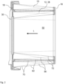
- figure 1 shows a perspective view of a two-stage filter system 100 with a cyclone separator 36 according to an embodiment of the invention with a tangential inlet 102, a central outlet 104 on a housing front side and a dirt outlet 106 on the bottom.
- a round filter design is shown, which consists of a housing 108 which has a housing wall 112 and is closed with a cover 110, for example with a screw or bayonet lock.
- dust-laden air flows into the inlet 102, which is arranged tangentially to the internally installed air filter element, so that the air inside the housing 108 is set into a rotational movement by an inflow protection on the filter element. Filter element and flow protection are not shown in the drawing.
- Such filter systems are usually used as air and / or particle filters in particular for internal combustion engines in the field of construction and agricultural machinery. They are characterized by great robustness and have a short service life due to the high filter load. A filter system 100 with a loaded filter element must tolerate an increase in weight of 10 kg or more.
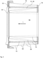
- FIG 2 shows a longitudinal section through a filter element 10 with an internal secondary element 12, 28, which is helpful for understanding the invention, the cone shapes of the semi-conical folds of the filter medium 56 pointing in the longitudinal axis L in the same direction.
- a filter element 10 is shown, in the interior 50 of which a second filter element 12 is arranged, which is used, for example, as a secondary element 28 .
- the filter element 10 is closed at both ends with a first and a second end plate 16, 18, which give the filter element 10 stability and ensure sealing when installed in a housing 108 of a filter system 100.
- the secondary element 28 is closed off at the top with an end disk 30 and is open at the bottom so that the filtered fluid can escape.
- the filter element 10 is arranged in such a way that the inner edges 72 of the folds of the filter medium 56 lie on the lateral surface of a cylinder, while the outer edges 70 lie on the lateral surface of a cone, with the filter element 12 being arranged in such a way that the inner edges 72 of the folds 62 of the Filter medium 56 lie on the lateral surface of a cone, while the outer edges 70 lie on the lateral surface of a cylinder.
- both filter elements 10, 12 can be arranged as close together as possible, while the interior of the filter elements 10, 12 opens wide in the opposite direction to the longitudinal axis L, in the outlet direction, thus ensuring a good flow for the filtered fluid.
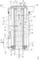
- FIG 3 shows a longitudinal section through a filter element 10 with an internal secondary element 12, 28, which is helpful for understanding the invention, the cone shapes of the semi-conical folds of the filter medium 56 pointing in the longitudinal axis L in the opposite direction.
- a filter element 10 is shown, in the interior 50 of which a second filter element 12 is arranged, which is used, for example, as a secondary element 28 .
- the filter element 10 is closed at both ends with a first and a second end plate 16, 18, which give the filter element 10 stability and ensure sealing when installed in a housing 108 of a filter system 100.
- the secondary element 28 is closed off at the top with an end disk 30 and is open at the bottom so that the filtered fluid can escape.
- the filter element 10 is arranged in such a way that the inner edges 72 of the folds 62 of the filter medium 56 lie on the lateral surface of a cylinder, while the outer edges 70 lie on the lateral surface of a cone, with the filter element 12 being arranged in such a way that the inner edges 72 of the folds 62 of the filter medium 56 lie on the lateral surface of a cylinder, while the outer edges 70 lie on the lateral surface of a cone.
- the interior 50 presents a cylindrical open Area is, so that the filter element 12 can be plugged, for example, on a cylindrical support tube.
- FIG 4 1 is a longitudinal section through a filter system 100 according to an exemplary embodiment of the invention, in which the filter medium 56 of the filter element 10 has a straight fold and an internal secondary element 28 as the second filter element 12 has a semi-conical fold.
- the housing 108 of the filter system 100 which comprises a housing wall 112, is closed with a cover 110 at one end.
- the filter medium 56 can, for example, be folded in a zigzag shape, be closed in the form of a ring and consist, for example, of paper or of cellulose or of a mixed fiber made of plastic and cellulose.
- the second end plate 18 has support knobs 20 which, when installed in the receiving housing 108 , resting against an inner cover contour 114 of the cover 110 , are supported on the housing 108 both axially and radially.
- a radial seal 26 is attached to the first end plate 16 on the opposite end face 15 of the filter element 10, with the aid of which the filter element 10 is supported radially with a radial seal 26 via the sealing contour 116 on the housing 108 and seals the unfiltered air space from the filtered air space.
- the filter element 10 is thus braced against the housing 108 both axially and doubly radially.
- Dust-laden air can flow in through the inlet 102 in the direction of the arrow 40 , which in this case is shown as a tangential inlet and enables cyclone operation due to the rotational movement of the air brought about with the aid of a cyclone separator 36 .
- Dust particles partially pre-separated by the rotational movement, can deposit on the inner housing wall and be emptied downwards through the dirt outlet 106 when the filter housing 108 is installed in a horizontal position by gravity out of the filter system 100 .
- the air flows through the filter medium 56 in the direction of the arrow 42, 44 into the interior 50 of the filter element.
- dust particles get stuck in the filter medium 56 from a certain size.
- the filter element 10 must therefore be replaced after a certain downtime.
- the filtered air flows out in the direction of arrow 46 via the outlet 104 .
- the secondary element 28 is attached, which essentially consists of a supporting structure, the support tube 14 and a relatively permeable filter medium 56, which is figure 4 is shown folded in a semiconical manner, and when the filter element 10 is replaced in the housing 108 to protect the further air duct, for example an internal combustion engine, against penetrating dust particles and other objects.
- the secondary element 28 is attached to the outlet-side part of the housing 108 and sealed with a radial seal.
- the cone of the semi-conical folds of the secondary element 28 is arranged in such a way that it opens in the opposite direction to the longitudinal direction L, ie in the outlet direction, in order to represent the lowest possible flow resistance for the filtered fluid.
- the inner edges 72 of the folds 62 of the secondary element 28 lie on the lateral surface of a cone, while the outer edges 70 lie on the lateral surface of a cylinder.
- the filter medium 56 of the filter element 10 has a straight fold, in which the inner and outer edges 72, 70 of the folds 62 lie on the lateral surfaces of a cylinder.
- the secondary element 28 can be designed cylindrical in its outer contour and thus can be plugged onto a support tube 14 fixed to the housing.
- a secondary element 28, equipped with fleece can optionally be provided in the same housing for low requirements with regard to the degree of separation and pressure loss.
- a larger filter surface can be provided on the secondary element 28 by a possibly smaller fold division, in comparison to a straight fold of the same fold height 74 (on the outlet side).
- the larger filter surface also applies to the comparison with the fleece medium, which cannot be folded at all at this low height and thus only forms the cylindrical surface of the outer contour.
- the large filter area together with the still large outlet cross-section on the outlet side then offers the advantage of a very low pressure loss.
- figure 5 12 shows a longitudinal section through a filter system 100 useful for understanding the invention, in which the filter medium 56 of the filter element 10 and the inner secondary element 28 have a semi-conical fold pointing in the longitudinal axis L in the same direction.
- the cone of the semi-conical folds of the secondary element 28 is arranged in such a way that it opens in the opposite direction to the longitudinal direction L, ie in the outlet direction, in order to represent the lowest possible flow resistance for the filtered fluid.
- Both the inner edges 72 of the folds 62 of the secondary element 28 and the outer edges 70 lie on the lateral surfaces of two cone shapes.
- the secondary element 28 is mounted on a support tube 14 which is also conical.
- the filter medium 56 of the filter element 10 also has a semi-conical fold, in which the inner edges 72 on the lateral surface of a cone and the Outer edges 70 of the folds 62 lie on the lateral surfaces of a cylinder.
- the cone shape of the secondary element 28 like the cone shape of the filter element 10, is open in the opposite direction to the longitudinal axis L, i.e. in the outlet direction, the tightest possible packing of the filter element 10 and the secondary element 28 is possible, so that the interior 50 of the filter element 10 extends as far as possible towards the outlet 104 can open towards and thus opposes the lowest possible flow resistance to the filtered fluid.
- a larger filter area can be provided on the secondary element 28 due to a possible smaller fold division compared to straight folds of the same fold height 74 (on the outlet side).
- the larger filter surface also applies to the comparison with the fleece medium, which cannot be folded at all at this low height and thus only forms the cylindrical surface of the outer contour.
- the large filter surface together with the still large outlet cross-section on the seal side then offers the advantage of a very low pressure loss.
- the filter element 10 equipped with semi-conical folds now offers the possibility, on the one hand, of opening the outlet cross-section further on the outlet side by reducing the fold height 74 on this side (positive for the pressure loss), and on the other hand of not having any loss of filter area, because the Pleat height 74 is twice as large on the closed side.
- the specific dust load (dust mass per filter area) of the filter element is improved because large amounts of dust can be absorbed through the large interstices in the pockets of the folds 62 .
- FIG 6 1 is a longitudinal section through a filter system 100 helpful for understanding the invention, in which the filter medium 56 of the filter element 10 has a semi-conical fold and the filter medium 56 of the secondary element 28 consists of a fleece.
- the filter medium 56 of the filter element 10 has a semi-conical fold in which the inner edges 72 lie on the lateral surface of a cone and the outer edges 70 of the folds 62 lie on the lateral surfaces of a cylinder.
- the secondary element 28 is adapted to the conical shape of the inner edges 72 of the filter element 10 and comprises a fleece that is attached to a cone-shaped support tube 14 .
- the conical shape of the filter medium 56 in the form of a fleece as the secondary element 28 enables a large outlet opening and a larger filter area than a comparable straight secondary element 28 made of a fleece and having a smaller diameter.
- the secondary element 28 thus does not require its own central tube made of plastic or metal and can therefore be produced more cost-effectively.
- a plastic ring 32 to which the fleece is attached and to which an O-ring seal 34 is provided is useful for stiffening.
- a simple star-folded filter bellows in a conical shape adapted to the inside of the filter element 10 can be used, which preferably has a constant fold height that is low compared to the filter element 10, for example less than or equal to 10 mm, preferably less than or equal to 5 mm .
- the filter element 10 equipped with semi-conical folds now offers the possibility, on the one hand, of opening the outlet cross-section further on the outlet side by reducing the fold height 74 on this side (positive for the pressure loss), and on the other hand of not having any loss of filter area, because the Pleat height 74 is twice as large on the closed side.
- the specific dust load (dust mass per filter area) of the filter element is improved because large amounts of dust can be absorbed through the large interstices in the pockets of the folds 62 .
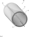
- FIG 7 shows a filter element 10 according to an embodiment of the invention with semi-conical folds of the filter medium 56.
- the filter element 10 is closed at both ends with a first and a second end plate 16, 18, which are used for the stability of the filter element 10 and for sealing during installation in the housing 108 of a filter system 100 are used.
- the filter medium 56 has a semi-conical fold such that the outer edges 70 of the folds 62 lie on the lateral surface of a cylinder and the inner edges 72 lie on the lateral surface of a cone.
- figure 8 further shows a filter medium 56 according to an embodiment of the invention with semi-conical folds of the filter medium 56.
- the outer edges 70 of the folds 62 of the filter medium 56 lie on the lateral surface of a cylinder and the inner edges 72 lie on the lateral surface of a cone.
- the folds 62 become denser in the longitudinal direction L, while the fold height 74 decreases continuously in the longitudinal direction L, so that the cone consequently opens in the longitudinal direction L.
- the filter medium 56 thus has a flow resistance that is variable along the longitudinal axis L, whereby it increases on the outside in the exemplary embodiment shown, while it decreases along the longitudinal axis L on the inside due to the opening inner cross section.
Description
Die Erfindung betrifft ein Filtersystem mit einem Filterelement, insbesondere zur Verwendung als Luftfilter einer Brennkraftmaschine, sowie ein Filterelement zum Einbau in ein solches Filtersystem.The invention relates to a filter system with a filter element, in particular for use as an air filter of an internal combustion engine, and a filter element for installation in such a filter system.
Der Aufbau von Filtersystemen, in denen Rundfilterelemente zum Einsatz kommen, ist aus dem Stand der Technik bekannt. Die Rundfilterelemente werden im Einsatz häufig von außen nach innen durchströmt, wobei das filtrierte Fluid aus dem zylindrischen Innenraum durch eine Öffnung im Deckel oder Boden des Rundfilterelementes zum Ausgang des Filtergehäuses geleitet wird. Der Durchmesser der Ausgangsöffnung in der Abdeckung des Rundfilterelements ist durch den Durchmesser des Innenraums des Filterelements begrenzt. Dieser ergibt sich aus dem Durchmesser des Filterelements abzüglich der Faltenhöhe des eingesetzten Filtermediums.The structure of filter systems in which round filter elements are used is known from the prior art. In use, the round filter elements are frequently flowed through from the outside in, with the filtered fluid being guided from the cylindrical interior through an opening in the cover or bottom of the round filter element to the outlet of the filter housing. The diameter of the outlet opening in the cover of the round filter element is limited by the diameter of the interior of the filter element. This results from the diameter of the filter element minus the fold height of the filter medium used.
Einerseits erlaubt eine möglichst große Faltenhöhe eine große effektive Filterfläche des Filterelements bei gleichbleibenden Außenabmessungen. Andererseits muss die Ausgangsöffnung für das gefilterte Fluid einen ausreichenden Querschnitt aufweisen, um das Fluid ableiten zu können. Bei vorgegebenen Abmessungen des Filterelements ist daher zwischen diesen beiden Gestaltungseinflüssen abzuwägen und ein Kompromiss zu finden.On the one hand, the largest possible fold height allows a large effective filter surface of the filter element with the same external dimensions. On the other hand, the outlet opening for the filtered fluid must have a sufficient cross-section to be able to drain the fluid. Given the specified dimensions of the filter element, these two design influences must therefore be weighed up and a compromise found.
Aus der
Aus der
Aus der
Eine Aufgabe der Erfindung ist es daher, ein kompaktes Filtersystem mit wenigstens einem austauschbaren Filterelement aus einem Filtermedium so zu gestalten, dass eine möglichst hohe Abscheiderate für Staubpartikel bei günstigem Bauraum erreicht werden kann.It is therefore an object of the invention to design a compact filter system with at least one replaceable filter element made of a filter medium in such a way that the highest possible separation rate for dust particles can be achieved with a favorable installation space.
Eine weitere Aufgabe der Erfindung ist es, ein Filterelement zum Einbau in ein solches Filtersystem zu schaffen, mit dem eine möglichst hohe Abscheiderate für Staubpartikel bei günstigem Bauraum erreicht werden kann.A further object of the invention is to create a filter element for installation in such a filter system, with which the highest possible separation rate for dust particles can be achieved with a favorable installation space.
Die vorgenannten Aufgaben werden gelöst mit einem Filtersystem und einer Verwendung gemäß einem der unabhängigen Ansprüche.The aforementioned objects are achieved with a filter system and a use according to one of the independent claims.
Günstige Ausgestaltungen und Vorteile der Erfindung ergeben sich aus den weiteren Ansprüchen, der Beschreibung und der Zeichnung.Favorable configurations and advantages of the invention result from the further claims, the description and the drawing.
Es wird ein Filtersystem mit einem oder mehreren, mit wenigstens einem Filtermedium ausgestatteten Filterelementen vorgeschlagen, wobei sich wenigstens ein Filterelement entlang einer Längsachse erstreckt, wobei das Filtersystem ein Gehäuse mit Gehäusewand und einem Deckel umfasst, wobei am Gehäuse ein Einlass zum Zuführen eines zu filternden Fluids, insbesondere Luft, und ein Auslass zur Ableitung des gefilterten Fluids angeordnet ist, wobei das Filtermedium zickzackförmig gefaltet ist und eine Mehrzahl von sich entlang der Längsachse erstreckenden Außenkanten und den Außenkanten auf der gegenüberliegenden Seite des Filtermediums gegenüberliegende Innenkanten von Falten aufweist, und wobei das Filtermedium einen entlang der Längsachse veränderlichen Strömungswiderstand aufweist. Der entlang der Längsachse veränderliche Strömungswiderstand bewirkt eine besonders effektive Abscheidung von Partikeln, insbesondere Staubpartikeln aus dem zu filternden Fluid wie Luft. Dabei sind verschiedene vorteilhafte Ausführungsformen des Filtermediums möglich.A filter system with one or more filter elements equipped with at least one filter medium is proposed, with at least one filter element extending along a longitudinal axis, with the filter system comprising a housing with a housing wall and a cover, with an inlet on the housing for supplying a fluid to be filtered , in particular air, and an outlet for discharging the filtered fluid is arranged, wherein the filter medium is folded in a zigzag shape and has a plurality of outer edges extending along the longitudinal axis and the outer edges on the opposite side of the filter medium opposite inner edges of folds, and wherein the filter medium has a variable flow resistance along the longitudinal axis. The variable flow resistance along the longitudinal axis causes a particularly effective separation of particles, in particular dust particles, from the fluid to be filtered, such as air. Various advantageous embodiments of the filter medium are possible.
Erfindungsgemäß umfasst das Filtersystem ein erstes, mit wenigstens einem Filtermedium ausgestattetes Filterelement und ein im Inneren des Filterelements angeordnetes Sekundärelement, wobei sich das Filterelement und das Sekundärelement entlang einer Längsachse erstrecken, ein Gehäuse mit Gehäusewand und einem Deckel, einen am Gehäuse tangential angeordneten Einlass zum Zuführen eines zu filternden Fluids, insbesondere Luft, einen am Gehäuse angeordneten zentrischen Auslass zur Ableitung des gefilterten Fluids, wobei das Filtermedium des Filterelements zickzackförmig gefaltet und ringförmig geschlossen ausgeführt ist und eine Mehrzahl von sich entlang der Längsachse erstreckenden Außenkanten und den Außenkanten auf der gegenüberliegenden Seite des Filtermediums gegenüberliegende Innenkanten von Falten aufweist, wobei die Außenkanten und die Innenkanten der Falten auf den Mantelflächen eines Zylinders liegen, wobei das Filtermedium des Sekundärelements zickzackförmig gefaltet und ringförmig geschlossen ausgeführt ist und eine Mehrzahl von sich entlang der Längsachse erstreckenden Außenkanten und den Außenkanten auf der gegenüberliegenden Seite des Filtermediums gegenüberliegende Innenkanten von Falten aufweist, wobei die Außenkanten der Falten auf einer Mantelfläche eines Zylinders liegen und die Innenkanten auf der Mantelfläche eines Konus liegen, wobei die Faltenhöhe auf Auslassseite verringert ist, und wobei das Filtermedium des Sekundärelements einen entlang der Längsachse veränderlichen Strömungswiderstand aufweist.According to the invention, the filter system comprises a first filter element equipped with at least one filter medium and a secondary element arranged inside the filter element, with the filter element and the secondary element extending along a longitudinal axis, a housing with a housing wall and a cover, an inlet arranged tangentially on the housing for feeding of a fluid to be filtered, in particular air, a central outlet arranged on the housing for discharging the filtered fluid, the filter medium of the filter element being folded in a zigzag shape and closed in the shape of a ring and having a plurality of outer edges extending along the longitudinal axis and the outer edges on the opposite side of the Filter medium has opposite inner edges of folds, the outer edges and the inner edges of the folds lying on the lateral surfaces of a cylinder, wherein the filter medium of the secondary element is folded in a zigzag shape and is closed in the form of a ring and one Having a plurality of outer edges extending along the longitudinal axis and inner edges of folds opposite the outer edges on the opposite side of the filter medium, the outer edges of the folds lying on a lateral surface of a cylinder and the inner edges lying on the lateral surface of a cone, the fold height being reduced on the outlet side and wherein the filter medium of the secondary element has a flow resistance variable along the longitudinal axis.
Der Deckel des Gehäuses kann in einer bevorzugten Ausführungsform an einer Stirnseite des Gehäuses angeordnet sein und somit konzentrisch um die Längsachse aufgebaut sein, während der Einlass in der Gehäusewand oder dem Deckel angeordnet sein kann. Der Auslass kann weiter konzentrisch zur Längsachse angeordnet sein, um das Filtersystem besonders bauraumsparend verbauen zu können.In a preferred embodiment, the cover of the housing can be arranged on an end face of the housing and thus be constructed concentrically around the longitudinal axis, while the inlet can be arranged in the housing wall or the cover. The outlet can also be arranged concentrically to the longitudinal axis in order to be able to install the filter system in a particularly space-saving manner.
In einer erfindungsgemäßen Ausgestaltung als sogenanntes plissiertes, d.h. zickzackförmig, gefaltetes Filtermedium, insbesondere sterngefaltetes Filtermedium, können die Außenkanten des Filtermediums von dem zu filternden Fluid angeströmt werden, sodass die abgelagerten Schmutzpartikel auf der Außenseite des Filtermediums verbleiben, jedoch können auch andere Anströmbedingungen vorteilhaft sein. Bei einem sterngefalteten Filtermedium ist dieses in sich geschlossen, z. B. mit einem ringförmigen oder eckigen Querschnitt. So kann das Filtermedium auch von außen nach innen oder umgekehrt durchströmt werden.In an embodiment according to the invention as a so-called pleated, i.e. zigzag, folded filter medium, in particular star-folded filter medium, the fluid to be filtered can flow against the outer edges of the filter medium, so that the deposited dirt particles remain on the outside of the filter medium, but other flow conditions can also be advantageous. With a star-pleated filter medium, this is self-contained, e.g. B. with an annular or angular cross-section. In this way, the filter medium can also be flowed through from the outside to the inside or vice versa.
Zum einen können die Außenkanten der Falten auf einer Mantelfläche eines Zylinders liegen und die Innenkanten zumindest teilweise auf der Mantelfläche eines Konus liegen. Dies hat den Vorteil, dass die äußere Bauform des Filterelements und damit des Filtersystems zylindrisch sein kann, was für eine Reihe von Anwendungen mit geringem Bauraumangebot von Nutzen sein kann. Die zylinderförmige Mantelfläche ist dadurch gekennzeichnet, dass sie entlang der Längsachse den gleichen Radius, also gerade Wände, aufweist. Die konusförmige Mantelfläche zeigt dagegen entlang der Längsachse eine Änderung des Radius, also eine kegelförmige Gestalt, wobei in der erfindungsgemäßen Ausführungsform ein Öffnungswinkel des Konus im Bereich von 1° bis typischerweise 10°, bevorzugt zwischen 1° und 5°, liegen kann.On the one hand, the outer edges of the folds can lie on a lateral surface of a cylinder and the inner edges can lie at least partially on the lateral surface of a cone. This has the advantage that the outer design of the filter element and thus of the filter system can be cylindrical, which can be useful for a number of applications where space is limited. The cylindrical lateral surface is characterized in that it has the same radius along the longitudinal axis, ie straight walls. The cone-shaped lateral surface, on the other hand, shows a change in radius along the longitudinal axis, i.e. a conical shape, with an opening angle of the cone in the embodiment according to the invention being in the range from 1° to typically 10°, preferably between 1° and 5°.
Eine Faltung des Filtermediums, bei der mindestens eine Kante der Falten auf der Mantelfläche eines Konus liegt, wird im Folgenden als halbkonische Faltung bezeichnet.Folding of the filter medium in which at least one edge of the folds lies on the lateral surface of a cone is referred to below as a semi-conical fold.
Generell ist zwar eine zylinderförmige Bauform eines Filtersystems sehr verbreitet und zweckmäßig für den Einbau in Bauräume von Brennkraftmaschinen, jedoch können die äußeren Abmessungen auch eckige oder flache Formen aufweisen, die so auch eckige und/oder flache Mantelflächen für die Außenkanten von Falten des Filtermediums zur Folge haben können.In general, a cylindrical design of a filter system is very common and useful for installation in the installation space of internal combustion engines, but the external dimensions can also have angular or flat shapes, which also result in angular and/or flat lateral surfaces for the outer edges of folds in the filter medium can have.
Aus dem Stand der Technik sind bei Rundluftfiltern so genannte sterngefaltete Filterelemente mit gerader Falte in zylindrischer oder konischer Bauform bekannt. Auch Sekundärelemente, also Filterelemente, die im Inneren der eigentlichen Filterelemente zur Absicherung des Reinluftbereichs vor Verschmutzung beim Wechsel von Filterelementen eingesetzt werden, mit Vliesmaterial ummantelt, auch wiederrum in zylindrischer oder konischer Bauform, gehören zum Stand der Technik. Der Einsatz einer halbkonischen Faltung wie oben beschrieben ist in zweistufigen Luftfiltern mit Zyklonabscheidern, mit oder ohne nachgeschaltetes Sekundärelement, in zylindrischer oder konischer Bauform besonders vorteilhaft, da so eine besonders effektive Partikelabscheidung bei besonders geringem Bauraumbedarf möglich ist.In the case of circular air filters, so-called star-pleated filter elements with straight folds in a cylindrical or conical design are known from the prior art. Secondary elements, i.e. filter elements that are used inside the actual filter elements to protect the clean air area from contamination when changing filter elements, covered with fleece material, also in cylindrical or conical design, belong to the prior art. The use of a semi-conical fold as described above is particularly advantageous in two-stage air filters with cyclone separators, with or without a downstream secondary element, in a cylindrical or conical design, since particularly effective particle separation is possible with a particularly small installation space requirement.
Weitere Vorteile liegen in einer besseren Luftführung mit möglichen größeren Querschnitten, beispielsweise im Bereich des Reinluftauslasses, was dazu führt, dass der Druckverlust des Gesamtluftfilters reduziert werden kann. Außerdem ist die spezifische Staubbeladung, also die Staubmasse pro Filterfläche am eigentlichen Filterelement besser, was zu größeren Standzeiten des Filterelements bei trotzdem gleichem Bauraum führt.Further advantages lie in better air guidance with possible larger cross sections, for example in the area of the clean air outlet, which means that the pressure loss of the entire air filter can be reduced. In addition, the specific dust load, i.e. the dust mass per filter area on the actual filter element, is better, which leads to a longer service life of the filter element with the same installation space.
Im Bereich des Einlasses des Filtersystems ist ein Zyklonabscheider vorgesehen (zweistufiges Luftfiltersystem) und am Gehäuse oder am Deckel ist ein Schmutzauslass vorgesehen. Dieser Zyklonabscheider besteht aus einer Leitgeometrie, die das zu filternde Fluid in eine Rotation versetzt. Durch diese Rotation wird der Schmutz im Bereich der Gehäusewand aufkonzentriert und an einer geeigneten Stelle über einen Schmutzauslass ausgetragen. Durch die Vorabscheidung des größten Teils an Schmutz aus der zu filternden Luft kann die Standzeit des eigentlichen Filterelements entscheidend verlängert werden.A cyclone separator is provided in the area of the inlet of the filter system (two-stage air filter system) and a dirt outlet is provided on the housing or on the cover. This cyclone separator consists of a guide geometry that causes the fluid to be filtered to rotate. This rotation concentrates the dirt in the area of the housing wall and discharges it at a suitable point via a dirt outlet. By pre-separating most of the dirt from the air to be filtered, the service life of the actual filter element can be significantly extended.
Zweckmäßigerweise kann sich in einer vorteilhaften Ausführungsform eine Faltenhöhe der Falten entlang der Längsachse kontinuierlich ändern. Auf diese Weise ist eine effektive Darstellung der halbkonisch gefalteten Bauform eines erfindungsgemäßen Filtermediums besonders günstig ermöglicht. Weiter kann so der Strömungswiderstand entlang der Längsachse kontinuierlich eingestellt werden, um die Abscheidungsrate der Partikel günstig zu beeinflussen.In an advantageous embodiment, a fold height of the folds can expediently change continuously along the longitudinal axis. In this way, an effective presentation of the semi-conically folded design of a filter medium according to the invention is made possible in a particularly favorable manner. Furthermore, the flow resistance along the longitudinal axis can be continuously adjusted in order to favorably influence the separation rate of the particles.
In dem erfindungsgemäßen Filtersystem ist eines von zwei Filterelementen im Inneren des anderen der Filterelemente angeordnet. Ein solches zweistufiges Filtersystem ist gerade für den Einsatz unter anspruchsvollen Bedingungen wie großem Staubanfall, beispielsweise im Bau- und Landmaschinenbereich, von großem Vorteil, da beim Wechsel des äußeren Filterelements das innere Filterelement den Reinluftauslass vor Verschmutzung wirkungsvoll schützen kann.In the filter system according to the invention, one of two filter elements is arranged inside the other of the filter elements. Such a two-stage filter system is particularly advantageous for use under demanding conditions such as large amounts of dust, for example in construction and agricultural machinery, since the inner filter element can effectively protect the clean air outlet from contamination when the outer filter element is changed.
Erfindungsgemäß ist ein Sekundärelement im Inneren des Filterelements angeordnet. Das Sekundärelement, das aus einer tragenden Struktur bestehen kann, die mit einem durchlässigen Filtermedium, beispielsweise einem Vlies, verkleidet ist, hat die Aufgabe, bei einem Austausch des Filterelements den Auslass des Filtersystems weiterhin verschlossen zu halten, so dass kein Schmutz in diesen Bereich eindringen kann, während das Filterelement gereinigt oder erneuert wird. Ein solches Filtersystem ist gerade für den Einsatz unter anspruchsvollen Bedingungen wie großem Staubanfall, beispielsweise im Bau- und Landmaschinenbereich, von großem Vorteil, da beim Wechsel des äußeren Filterelements das Sekundärelement den Reinluftauslass vor Verschmutzung wirkungsvoll schützen kann. Das Sekundärelement kann in bevorzugter Ausgestaltung über eine Schraubverbindung mit dem Gehäuse verbunden und zum Gehäuse mit einer Dichtung versehen sein.According to the invention, a secondary element is arranged inside the filter element. The secondary element, which may consist of a supporting structure covered with a permeable filter medium, e.g a fleece, has the task of keeping the outlet of the filter system closed when the filter element is replaced, so that no dirt can penetrate this area while the filter element is being cleaned or replaced. Such a filter system is particularly advantageous for use under demanding conditions such as large amounts of dust, for example in construction and agricultural machinery, since the secondary element can effectively protect the clean air outlet from contamination when the outer filter element is changed. In a preferred embodiment, the secondary element can be connected to the housing via a screw connection and can be provided with a seal relative to the housing.
Vorteilhaft kann dabei ein Stützrohr im Inneren des Sekundärelements angeordnet sein. Durch das Stützrohr kann ein in sich instabiles Filterelement wie auch ein Sekundärelement versteift werden, um so sowohl gegen Strömungsdruck als auch mechanische Erschütterungen im Betrieb an einer Brennkraftmaschine die ursprüngliche Form zu behalten und die bestimmungsgemäße Funktion weiter zuverlässig auszuüben.A support tube can advantageously be arranged in the interior of the secondary element. An inherently unstable filter element as well as a secondary element can be reinforced by the support tube in order to retain the original shape against both flow pressure and mechanical shocks during operation of an internal combustion engine and continue to reliably perform the intended function.
In einer Ausführungsform kann das Sekundärelement mit dem Gehäuse verbunden sein und beim Wechsel des Filterelements im Gehäuse verbleiben. Dadurch ist der Reinluftauslass bei Wechsel des Filterelements besonders wirksam gegen Verschmutzung geschützt. Auch kann die feste Anbringung des Sekundärelements am Gehäuse die Herstellung einer besonders kostengünstigen Ausführungsform des Filtersystems begünstigen.In one embodiment, the secondary element can be connected to the housing and can remain in the housing when the filter element is changed. As a result, the clean air outlet is particularly effectively protected against contamination when the filter element is changed. The fixed attachment of the secondary element to the housing can also promote the production of a particularly cost-effective embodiment of the filter system.
ist das Sekundärelement nicht mit dem Gehäuse fest verbunden, sondern wechselbar ausgeführt, dann kann eine Endscheibe des Sekundärelements zur besseren Montage/ Demontage als Handgriff ausgebildet sein.if the secondary element is not permanently connected to the housing, but is designed to be exchangeable, then an end plate of the secondary element can be designed as a handle for better assembly/disassembly.
Zweckmäßigerweise kann wenigstens eines der ein oder mehreren Filterelemente auswechselbar in dem Gehäuse des Filtersystems angeordnet sein. Gerade beim Einsatz eines Filtersystems unter besonders rauen Umweltbedingungen können Filterelemente so mit Staub beladen werden, dass sie in relativ kurzen zeitlichen Abständen getauscht werden müssen und dabei natürlich nicht jedes Mal das gesamte Filtersystem ausgetauscht werden soll, was zu erheblichem Mehraufwand an Betriebskosten führen würde.At least one of the one or more filter elements can expediently be arranged in an exchangeable manner in the housing of the filter system. Especially when using a filter system under particularly harsh environmental conditions, filter elements can become so loaded with dust that they have to be replaced at relatively short intervals and of course the entire filter system does not have to be replaced every time, which would lead to considerable additional expenditure on operating costs.
Vorteilhaft kann eine Verwendung eines Filtersystems als Luftfilter, insbesondere als Luftfilter einer Brennkraftmaschine sein.Using a filter system as an air filter, in particular as an air filter of an internal combustion engine, can be advantageous.
In einer günstigen Ausgestaltung kann das Filtermedium beispielsweise aus einem zickzackförmig gefalteten (plissierten) Filterbalg bestehen und ringförmig geschlossen ausgeführt sein. Die Faltung kann beispielsweise durch Messerfaltung, für längere Filterkörper, oder Rotationsfaltung hergestellt werden. Der Filterbalg kann beispielsweise aus Papier oder aus Zellulose oder aus einer Mischfaser aus Kunststoff und Zellulose bestehen. Der Filterbalg kann ferner mit glatter Oberfläche, rolliert und/oder in verschiedenen Prägeformen gestalteter Oberfläche zur Versteifung und/oder Schaffung von Hohlräumen zur Staubablagerung ausgeführt sein. Der Filterbalg kann eine Beschichtung und/oder Imprägnierung aufweisen, um Feuchtigkeit abzuweisen. Er kann alternativ auch mit so genannten Nanofasern beschichtet sein. Der Filterkörper kann weiterhin mit einem Fadenwickel strukturell versteift sein. Dabei ist ein Faden um den Umfang des Filterkörpers gewickelt. Es können auch mehrere Fadenwickel auf unterschiedlichen axialen Höhen des Filterkörpers vorgesehen sein. Der Einsatz dieser Werkstoffe als Filtermedium stellt eine sehr wirtschaftliche Möglichkeit dar, ein solches Filterelement zu realisieren. Gleichzeitig bietet die beschriebene Formgestaltung eine stabile Anordnung, sodass eine selbsttragende Bauweise des Filterkörpers und damit eine günstige Montageeigenschaft gegeben sind.In a favorable embodiment, the filter medium can consist, for example, of a filter bellows folded in a zigzag shape (pleated) and be designed closed in the form of a ring. The folds can be made, for example, by knife folds, for longer filter bodies, or rotary folds. The filter bellows can consist, for example, of paper or of cellulose or of a mixed fiber made of plastic and cellulose. The filter bellows can also have a smooth surface, be rolled and/or have a surface designed in various embossing forms for stiffening and/or creating cavities for dust deposits. The filter bellows can have a coating and/or impregnation to repel moisture. Alternatively, it can also be coated with so-called nanofibers. The filter body may be further structurally stiffened with a filament wrap. A thread is wound around the circumference of the filter body. Several thread windings can also be provided at different axial heights of the filter body. The use of these materials as a filter medium represents a very economical way of realizing such a filter element. At the same time, the shape design described offers a stable arrangement, so that a self-supporting construction of the filter body and thus favorable assembly properties are provided.
Weitere Vorteile ergeben sich aus der folgenden Zeichnungsbeschreibung. In den Zeichnungen sind Ausführungsbeispiele der Erfindung dargestellt. Die Zeichnungen, die Beschreibung und die Ansprüche enthalten zahlreiche Merkmale in Kombination. Der Fachmann wird die Merkmale zweckmäßigerweise auch einzeln betrachten und zu sinnvollen weiteren Kombinationen zusammenfassen.Further advantages result from the following description of the drawing. Exemplary embodiments of the invention are shown in the drawings. The drawings, the description and the claims contain numerous features in combination. The person skilled in the art will expediently also consider the features individually and combine them into further meaningful combinations.
- Fig. 11
- eine perspektivische Ansicht eines zweistufigen Filtersystems mit einem Zyklonabscheider nach einem Ausführungsbeispiel der Erfindung;a perspective view of a two-stage filter system with a cyclone separator according to an embodiment of the invention;
- Fig. 22
- einen Längsschnitt durch ein für das Verständnis der Erfindung hilfreiches Filterelement mit innen liegendem Sekundärelement, wobei die Konusformen der halbkonischen Faltung in der Längsachse in dieselbe Richtung zeigen;a longitudinal section through a helpful for understanding the invention filter element with internal secondary element, wherein the cone shapes of the semi-conical folds in the longitudinal axis in the same direction;
- Fig. 33
- einen Längsschnitt durch ein für das Verständnis der Erfindung hilfreiches Filterelement mit innen liegendem Sekundärelement, wobei die Konusformen der halbkonischen Faltung in der Längsachse in die entgegengesetzte Richtung zeigen;a longitudinal section through a helpful for understanding the invention filter element with internal secondary element, wherein the cone shapes of the semi-conical folds in the longitudinal axis in the opposite direction;
- Fig. 44
- einen Längsschnitt durch ein Filtersystem nach einem Ausführungsbeispiel der Erfindung, bei dem das Filtermedium des Filterelements eine gerade Faltung aufweist und ein innen liegendes Sekundärelement eine halbkonische Faltung aufweist;a longitudinal section through a filter system according to an embodiment of the invention, in which the filter medium of the filter element has a straight fold and an internal secondary element has a semi-conical fold;
- Fig. 5figure 5
- einen Längsschnitt durch ein für das Verständnis der Erfindung hilfreiches Filtersystem, bei dem das Filtermedium des Filterelements und das innen liegende Sekundärelement eine halbkonische Faltung aufweisen, die in der Längsachse in dieselbe Richtung zeigen;a longitudinal section through a helpful for understanding the invention filter system, in which the filter medium of the filter element and the internal secondary element have a semi-conical fold pointing in the longitudinal axis in the same direction;
- Fig. 66
- einen Längsschnitt durch ein für das Verständnis der Erfindung hilfreiches Filtersystem, bei dem das Filtermedium des Filterelements eine halbkonische Faltung aufweist und das Filtermedium des Sekundärelements aus einem Vlies besteht;a longitudinal section through a helpful for understanding the invention filter system, in which the filter medium of the filter element has a semi-conical fold and the filter medium of the secondary element consists of a fleece;
- Fig. 77
- ein Filterelement nach einem Ausführungsbeispiel der Erfindung mit halbkonischer Faltung des Filtermediums; unda filter element according to an embodiment of the invention with semi-conical pleating of the filter medium; and
- Fig. 88
- ein Filtermedium nach einem Ausführungsbeispiel der Erfindung mit halbkonischer Faltung des Filtermediums.a filter medium according to an embodiment of the invention with semi-conical folds of the filter medium.
In den Figuren sind gleiche oder gleichartige Komponenten mit gleichen Bezugszeichen beziffert. Die Figuren zeigen lediglich Beispiele und sind nicht beschränkend zu verstehen.In the figures, the same or similar components are denoted by the same reference symbols. The figures only show examples and are not to be understood as limiting.
Derartige Filtersysteme, wie in
In
Die zweite Endscheibe 18 weist Abstütznoppen 20 auf, welche bei einem Einbau in das aufnehmende Gehäuse 108 an einer inneren Deckelkontur 114 des Deckels 110 anliegend sich an dem Gehäuse 108 sowohl axial als auch radial abstützen. An der gegenüberliegenden Stirnseite 15 des Filterelements 10 ist an der ersten Endscheibe 16 eine Radialdichtung 26 angebracht, mit deren Hilfe das Filterelement 10 sich mit einer Radialdichtung 26 über die Dichtungskontur 116 an dem Gehäuse 108 radial abstützt und den ungefilterten gegen den gefilterten Luftraum abdichtet. Das Filterelement 10 ist damit sowohl axial als auch doppelt radial gegen das Gehäuse 108 verspannt.The
Staubbeladene Luft kann durch den Einlass 102 in Pfeilrichtung 40 einströmen, der in diesem Fall als tangentialer Einlass dargestellt ist und durch die mit Hilfe eines Zyklonabscheiders 36 bewirkte Rotationsbewegung der Luft einen Zyklonbetrieb ermöglicht. Staubpartikel können durch die Rotationsbewegung teilweise vorabgeschieden sich an der inneren Gehäusewand ablagern und durch den Schmutzauslass 106 bei Einbau des Filtergehäuses 108 in waagrechter Lage nach unten durch die Schwerkraft aus dem Filtersystem 100 entleert werden. Die Luft strömt beim Betrieb nach Teilabscheidung der Staubpartikel durch das Filtermedium 56 in Pfeilrichtung 42, 44 ins Innere 50 des Filterelements. Staubpartikel bleiben dabei je nach Filtermedium ab einer bestimmten Größe im Filtermedium 56 hängen. Je nach Staubeintrag muss deshalb das Filterelement 10 nach einer gewissen Standzeit ausgetauscht werden.Dust-laden air can flow in through the
Über den Auslass 104 strömt die gefilterte Luft in Pfeilrichtung 46 ab. Im Inneren 50 des Filterelements 10, also im Reinluftbereich, ist das Sekundärelement 28 angebracht, das im Wesentlichen aus einer tragenden Struktur, dem Stützrohr 14 und einem relativ durchlässigen Filtermedium 56, das in
Der Konus der halbkonischen Faltung des Sekundärelements 28 ist so angeordnet, dass er entgegengesetzt zur Längsrichtung L, also in Auslassrichtung, sich öffnet, um so einen möglichst geringen Strömungswiderstand für das gefilterte Fluid darzustellen. Die Innenkanten 72 der Falten 62 des Sekundärelements 28 liegen auf der Mantelfläche eines Konus, während die Außenkanten 70 auf der Mantelfläche eines Zylinders liegen. Das Filtermedium 56 des Filterelements 10 weist eine gerade Faltung auf, bei der die Innen- und Außenkanten 72, 70 der Falten 62 auf den Mantelflächen eines Zylinders liegen.The cone of the semi-conical folds of the secondary element 28 is arranged in such a way that it opens in the opposite direction to the longitudinal direction L, ie in the outlet direction, in order to represent the lowest possible flow resistance for the filtered fluid. The
Der Vorteil des in
Durch die halbkonische Ausführung kann an dem Sekundärelement 28 durch eine mögliche kleinere Faltenteilung eine größere Filterfläche vorgesehen werden, im Vergleich zu einer geraden Faltung gleicher Faltenhöhe 74 (auf der Auslassseite). Die größere Filterfläche trifft auch auf den Vergleich mit dem Vliesmedium zu, das ja in dieser geringen Höhe überhaupt nicht gefaltet werden kann und somit lediglich die Zylinderfläche der Außenkontur bildet.Due to the semi-conical design, a larger filter surface can be provided on the secondary element 28 by a possibly smaller fold division, in comparison to a straight fold of the same fold height 74 (on the outlet side). The larger filter surface also applies to the comparison with the fleece medium, which cannot be folded at all at this low height and thus only forms the cylindrical surface of the outer contour.
Die große Filterfläche zusammen mit dem nach wie vor großen Auslassquerschnitt auf der Auslassseite bietet dann den Vorteil eines sehr geringen Druckverlusts.The large filter area together with the still large outlet cross-section on the outlet side then offers the advantage of a very low pressure loss.
Der Konus der halbkonischen Faltung des Sekundärelements 28 ist so angeordnet, dass er entgegengesetzt zur Längsrichtung L, also in Auslassrichtung, sich öffnet, um so einen möglichst geringen Strömungswiderstand für das gefilterte Fluid darzustellen. Sowohl die Innenkanten 72 der Falten 62 des Sekundärelements 28 als auch die Außenkanten 70 liegen auf den Mantelflächen von zwei Konusformen. Das Sekundärelement 28 ist auf einem ebenfalls konischen Stützrohr 14 angebracht. Das Filtermedium 56 des Filterelements 10 weist ebenfalls eine halbkonische Faltung auf, bei der die Innenkanten 72 auf der Mantelfläche eines Konus und die Außenkanten 70 der Falten 62 auf den Mantelflächen eines Zylinders liegen. Da die Konusformen des Sekundärelements 28, wie die Konusform des Filterelements 10 entgegengesetzt zur Längsachse L, also in Auslassrichtung, geöffnet sind, ist eine möglichst dichte Packung von Filterelement 10 und Sekundärelement 28 möglich, sodass das Innere 50 des Filterelements 10 sich möglichst weit zum Auslass 104 hin öffnen kann und so einen möglichst geringen Strömungswiderstand dem gefilterten Fluid entgegensetzt.The cone of the semi-conical folds of the secondary element 28 is arranged in such a way that it opens in the opposite direction to the longitudinal direction L, ie in the outlet direction, in order to represent the lowest possible flow resistance for the filtered fluid. Both the
Der Vorteil des in
Durch die halbkonische Faltung des Filtermediums 56 kann am Sekundärelement 28 durch eine mögliche kleinere Faltenteilung eine größere Filterfläche vorgesehen werden im Vergleich zu einer geraden Faltung gleicher Faltenhöhe 74 (auf der Auslassseite). Die größere Filterfläche trifft auch auf den Vergleich mit dem Vliesmedium zu, das ja in dieser geringen Höhe überhaupt nicht gefaltet werden kann und somit lediglich die Zylinderfläche der Außenkontur bildet.Due to the semi-conical folds of the
Die große Filterfläche zusammen mit dem nach wie vor großen Auslassquerschnitt auf der Dichtungsseite bietet dann den Vorteil eines sehr geringen Druckverlusts.The large filter surface together with the still large outlet cross-section on the seal side then offers the advantage of a very low pressure loss.
Das mit halbkonischer Faltung ausgestattete Filterelement 10 bietet nun die Möglichkeit, zum einen auf der Auslassseite den Auslassquerschnitt weiter zu öffnen, indem die Faltenhöhe 74 auf dieser Seite verringert wird (positiv für den Druckverlust), und zum Anderen keinen Verlust an Filterfläche aufzuweisen, weil die Faltenhöhe 74 auf der geschlossenen Seite doppelt so groß ist. Außerdem wird die spezifische Staubbeladung (Staubmasse pro Filterfläche) des Filterelementes verbessert, weil durch die großen Zwischenräume in den Taschen der Falten 62 große Staubmengen aufgenommen werden können.The
In
Die Konusform des Filtermediums 56 in Gestalt eines Vlieses als Sekundärelement 28 ermöglicht eine große Auslassöffnung und eine größere Filterfläche als ein vergleichbares, im Durchmesser kleineres gerades Sekundärelement 28 aus einem Vlies.The conical shape of the
Das Sekundärelement 28 benötigt so kein eigenes Mittelrohr aus Kunststoff oder Metall und kann somit kostengünstiger hergestellt werden. Ein Kunststoffring 32, an dem das Vlies angebracht ist und an dem eine O-Ring-Dichtung 34 vorgesehen ist, ist zur Versteifung zweckmäßig.The secondary element 28 thus does not require its own central tube made of plastic or metal and can therefore be produced more cost-effectively. A
Alternativ kann statt eines Vlieses ein einfacher sterngefalteter Filterbalg in konischer, an die Innenseite des Filterelements 10 angepasster Form verwendet werden, der bevorzugt eine konstante und im Vergleich zum Filterelement 10 geringe Faltenhöhe aufweist, beispielsweise kleiner oder gleich 10 mm, bevorzugt kleiner oder gleich 5 mm.Alternatively, instead of a fleece, a simple star-folded filter bellows in a conical shape adapted to the inside of the
Das mit halbkonischer Faltung ausgestattete Filterelement 10 bietet nun die Möglichkeit, zum einen auf der Auslassseite den Auslassquerschnitt weiter zu öffnen, indem die Faltenhöhe 74 auf dieser Seite verringert wird (positiv für den Druckverlust), und zum Anderen keinen Verlust an Filterfläche aufzuweisen, weil die Faltenhöhe 74 auf der geschlossenen Seite doppelt so groß ist. Außerdem wird die spezifische Staubbeladung (Staubmasse pro Filterfläche) des Filterelementes verbessert, weil durch die großen Zwischenräume in den Taschen der Falten 62 große Staubmengen aufgenommen werden können.The
Claims (7)
- Filter system (100), comprising- a first filter element (10) equipped with at least one filter medium (56),- and a secondary element (28) disposed inside (50) the filter element (10), the filter element (10) and the secondary element extending along a longitudinal axis (L),- a housing (108) with housing wall (112) and a cover (110),- an inlet (102) tangentially disposed at the housing (108) for supplying a fluid to be filtered, in particular air,- a cyclone separator (36) which causes a rotational movement of the supplied fluid to be filtered, in particular the air,- a dirt outlet (106) through which dust particles partially pre-separated by the rotational movement and deposited on the inner housing wall are discharged,- a central outlet (104) disposed at the housing (108) for discharging the filtered fluid,wherein the filter medium (56) of the filter element (10) is zigzag-folded and realized in an annularly closed design and features a plurality of outer edges (70) extending along the longitudinal axis (L) and inner edges (72) of folds (62) opposing the outer edges (70) on the opposing side of the filter medium (56), wherein the outer edges (70) and the inner edges (72) of the folds (62) rest on the circumferential surfaces of a cylinder, wherein the filter medium (56) of the secondary element (28) is zigzag-folded and realized as an annularly closed design and features a plurality of outer edges (70) extending along the longitudinal axis (L) and inner edges (72) of folds (62) opposing the outer edges (70) on the opposing side of the filter medium (56), wherein the outer edges (70) of the folds (62) rest on a circumferential surface of a cylinder and the inner edges (72) rest on the circumferential surface of a cone, wherein the fold height on the outlet side is reduced, and wherein the filter medium (56) of the secondary element (28) features a variable flow resistance along the longitudinal axis (L).
- Filter system according to claim 1, wherein a fold height (74) of the folds (62) of the secondary element (28) changes continuously along the longitudinal axis (L).
- Filter system according to one of the above claims, wherein a support tube (14) is disposed inside the secondary element (28).
- Filter system according to one of the above claims, wherein a filter medium (56) of the secondary element (28) consists of a non-woven fabric.
- Filter system according to one of the above claims, wherein the secondary element (28) is connected to the housing (108) and remains in the housing (108) when changing the filter element (10).
- Filter system according to one of the above claims, wherein at least one of the filter elements (10, 12) is replaceably disposed in the housing (108) of the filter system (100).
- Use of a filter system (10) according to one of the above claims as air filter, in particular as air filter of an internal combustion engine.
Applications Claiming Priority (1)
| Application Number | Priority Date | Filing Date | Title |
|---|---|---|---|
| DE102013014492.2A DE102013014492A1 (en) | 2013-09-02 | 2013-09-02 | Filter system with filter element |
Publications (3)
| Publication Number | Publication Date |
|---|---|
| EP2862614A1 EP2862614A1 (en) | 2015-04-22 |
| EP2862614B1 EP2862614B1 (en) | 2018-12-05 |
| EP2862614B2 true EP2862614B2 (en) | 2023-08-23 |
Family
ID=51662994
Family Applications (1)
| Application Number | Title | Priority Date | Filing Date |
|---|---|---|---|
| EP14182486.2A Active EP2862614B2 (en) | 2013-09-02 | 2014-08-27 | Filter system with filter element |
Country Status (3)
| Country | Link |
|---|---|
| EP (1) | EP2862614B2 (en) |
| CN (2) | CN204543842U (en) |
| DE (1) | DE102013014492A1 (en) |
Families Citing this family (9)
| Publication number | Priority date | Publication date | Assignee | Title |
|---|---|---|---|---|
| DE102013014492A1 (en) | 2013-09-02 | 2015-03-05 | Mann + Hummel Gmbh | Filter system with filter element |
| DE102014016300B4 (en) * | 2014-11-06 | 2018-05-30 | Mann + Hummel Gmbh | Filter and use of a hollow filter element in this filter |
| DE102014016301A1 (en) | 2014-11-06 | 2016-05-25 | Mann + Hummel Gmbh | Hollow filter element of a filter for filtering fluid, filter, filter housing and sealing a hollow filter element |
| DE102014019901B3 (en) | 2014-11-06 | 2023-04-13 | Mann+Hummel Gmbh | filter |
| DE102016004315A1 (en) | 2016-04-12 | 2017-10-12 | Mann + Hummel Gmbh | A filter assembly |
| DE102016012327A1 (en) * | 2016-10-17 | 2018-04-19 | Mann + Hummel Gmbh | Round filter element, in particular for gas filtration |
| IT201800006072A1 (en) * | 2018-06-06 | 2019-12-06 | AIR FILTRATION DEVICE | |
| DE102018116506A1 (en) * | 2018-07-09 | 2020-01-09 | Mann+Hummel Gmbh | Secondary filter element and filter arrangement |
| EP4342564A1 (en) * | 2022-09-20 | 2024-03-27 | MANN+HUMMEL GmbH | Gas filter system |
Citations (2)
| Publication number | Priority date | Publication date | Assignee | Title |
|---|---|---|---|---|
| WO2009014986A1 (en) † | 2007-07-20 | 2009-01-29 | Donaldson Company, Inc. | Air cleaner arrangements with internal and external support for cartridge; components; and, methods |
| US7572310B2 (en) † | 2000-12-04 | 2009-08-11 | Donaldson Company, Inc. | Filter system; element configuration; and methods |
Family Cites Families (10)
| Publication number | Priority date | Publication date | Assignee | Title |
|---|---|---|---|---|
| US5522909A (en) | 1994-12-27 | 1996-06-04 | Purolator Products Na, Inc. | Air filter device |
| DE19849998A1 (en) | 1998-10-30 | 2000-05-04 | Mann & Hummel Filter | filter |
| CN100406102C (en) | 2002-10-28 | 2008-07-30 | 唐纳森公司 | Air cleaner, replaceable filter cartridges and methods |
| DE102008062954B4 (en) * | 2008-12-23 | 2023-06-15 | Mann+Hummel Gmbh | Filter device, in particular air filter for an internal combustion engine |
| US20090301042A1 (en) * | 2008-06-04 | 2009-12-10 | R2C Performance Products Llc | Gradient density engine intake filter media |
| DE202009016500U1 (en) * | 2009-12-07 | 2010-02-25 | Mahle International Gmbh | Filter element and air filter |
| US8888885B2 (en) | 2010-09-07 | 2014-11-18 | Cummins Filtration Ip Inc. | Filter and filter media having reduced restriction |
| DE102011018366B4 (en) * | 2011-04-20 | 2016-08-18 | Mann + Hummel Gmbh | Filter element for filtering intake air of an internal combustion engine |
| US20140144111A1 (en) | 2012-11-29 | 2014-05-29 | Donaldson Company Inc. | Filter cartridges; features and methods of assemlby; air cleaner assemblies; and, filter cartridge combinations |
| DE102013014492A1 (en) | 2013-09-02 | 2015-03-05 | Mann + Hummel Gmbh | Filter system with filter element |
-
2013
- 2013-09-02 DE DE102013014492.2A patent/DE102013014492A1/en not_active Ceased
-
2014
- 2014-08-27 EP EP14182486.2A patent/EP2862614B2/en active Active
- 2014-09-02 CN CN201420501618.1U patent/CN204543842U/en not_active Withdrawn - After Issue
- 2014-09-02 CN CN201410442143.8A patent/CN104415623B/en active Active
Patent Citations (2)
| Publication number | Priority date | Publication date | Assignee | Title |
|---|---|---|---|---|
| US7572310B2 (en) † | 2000-12-04 | 2009-08-11 | Donaldson Company, Inc. | Filter system; element configuration; and methods |
| WO2009014986A1 (en) † | 2007-07-20 | 2009-01-29 | Donaldson Company, Inc. | Air cleaner arrangements with internal and external support for cartridge; components; and, methods |
Also Published As
| Publication number | Publication date |
|---|---|
| EP2862614B1 (en) | 2018-12-05 |
| CN104415623B (en) | 2019-04-02 |
| CN104415623A (en) | 2015-03-18 |
| DE102013014492A1 (en) | 2015-03-05 |
| CN204543842U (en) | 2015-08-12 |
| EP2862614A1 (en) | 2015-04-22 |
Similar Documents
| Publication | Publication Date | Title |
|---|---|---|
| EP2862614B2 (en) | Filter system with filter element | |
| EP2742986B1 (en) | Air filter system, air filter element and method for exchanging an air filter element | |
| EP3470129B1 (en) | Air filter system and air filter element for an air filter system | |
| EP2851110A1 (en) | Filter element and filter system with a filter element | |
| EP1928574B1 (en) | Separator for liquids, in particular condensate, from liquid-loaded compressed gases | |
| EP2764905A1 (en) | Filter body | |
| EP2813275A1 (en) | Filter element and filter system | |
| EP3117904B1 (en) | Apparatus for separating particles from a fluid stream | |
| EP2249943A1 (en) | Multiple bellow-type filter with increased efficiency | |
| DE102013014489B4 (en) | Filter element, filter system with a filter element and use | |
| EP2765298B1 (en) | Filter element | |
| DE102014007373B4 (en) | Folded filter element | |
| EP2764904B1 (en) | Filter element | |
| WO2015018779A1 (en) | Water separating screen for a filter element in a liquid filter | |
| EP2853305A1 (en) | Filter element and filter system with a filter element | |
| EP1216743A1 (en) | Filter system | |
| DE102014012944A1 (en) | Filter system with filter element | |
| DE102013014498B4 (en) | Filter element, its use and filter system | |
| DE202013011868U1 (en) | Filter system and filter element for a filter system | |
| DE102014012941B4 (en) | Air filter system and method for improving the pre-separation of an air filter system | |
| DE102015003756A1 (en) | Filter element, in particular for liquid filtration | |
| DE102018001183A1 (en) | Air filter with low pressure loss | |
| WO2020193145A1 (en) | Filter element and filter system with a filter element | |
| DE1536796C (en) | Filter device for flowable media | |
| DE102014012943A1 (en) | Filter element and filter system with a filter element |
Legal Events
| Date | Code | Title | Description |
|---|---|---|---|
| PUAI | Public reference made under article 153(3) epc to a published international application that has entered the european phase |
Free format text: ORIGINAL CODE: 0009012 |
|
| 17P | Request for examination filed |
Effective date: 20140827 |
|
| AK | Designated contracting states |
Kind code of ref document: A1 Designated state(s): AL AT BE BG CH CY CZ DE DK EE ES FI FR GB GR HR HU IE IS IT LI LT LU LV MC MK MT NL NO PL PT RO RS SE SI SK SM TR |
|
| AX | Request for extension of the european patent |
Extension state: BA ME |
|
| R17P | Request for examination filed (corrected) |
Effective date: 20151022 |
|
| RBV | Designated contracting states (corrected) |
Designated state(s): AL AT BE BG CH CY CZ DE DK EE ES FI FR GB GR HR HU IE IS IT LI LT LU LV MC MK MT NL NO PL PT RO RS SE SI SK SM TR |
|
| STAA | Information on the status of an ep patent application or granted ep patent |
Free format text: STATUS: EXAMINATION IS IN PROGRESS |
|
| 17Q | First examination report despatched |
Effective date: 20170102 |
|
| GRAP | Despatch of communication of intention to grant a patent |
Free format text: ORIGINAL CODE: EPIDOSNIGR1 |
|
| STAA | Information on the status of an ep patent application or granted ep patent |
Free format text: STATUS: GRANT OF PATENT IS INTENDED |
|
| INTG | Intention to grant announced |
Effective date: 20180622 |
|
| GRAS | Grant fee paid |
Free format text: ORIGINAL CODE: EPIDOSNIGR3 |
|
| GRAA | (expected) grant |
Free format text: ORIGINAL CODE: 0009210 |
|
| STAA | Information on the status of an ep patent application or granted ep patent |
Free format text: STATUS: THE PATENT HAS BEEN GRANTED |
|
| RAP1 | Party data changed (applicant data changed or rights of an application transferred) |
Owner name: MANN + HUMMEL GMBH |
|
| AK | Designated contracting states |
Kind code of ref document: B1 Designated state(s): AL AT BE BG CH CY CZ DE DK EE ES FI FR GB GR HR HU IE IS IT LI LT LU LV MC MK MT NL NO PL PT RO RS SE SI SK SM TR |
|
| REG | Reference to a national code |
Ref country code: GB Ref legal event code: FG4D Free format text: NOT ENGLISH |
|
| REG | Reference to a national code |
Ref country code: CH Ref legal event code: EP |
|
| REG | Reference to a national code |
Ref country code: AT Ref legal event code: REF Ref document number: 1072359 Country of ref document: AT Kind code of ref document: T Effective date: 20181215 |
|
| REG | Reference to a national code |
Ref country code: IE Ref legal event code: FG4D Free format text: LANGUAGE OF EP DOCUMENT: GERMAN |
|
| REG | Reference to a national code |
Ref country code: DE Ref legal event code: R096 Ref document number: 502014010253 Country of ref document: DE |
|
| REG | Reference to a national code |
Ref country code: NL Ref legal event code: MP Effective date: 20181205 |
|
| REG | Reference to a national code |
Ref country code: LT Ref legal event code: MG4D |
|
| PG25 | Lapsed in a contracting state [announced via postgrant information from national office to epo] |
Ref country code: ES Free format text: LAPSE BECAUSE OF FAILURE TO SUBMIT A TRANSLATION OF THE DESCRIPTION OR TO PAY THE FEE WITHIN THE PRESCRIBED TIME-LIMIT Effective date: 20181205 Ref country code: LV Free format text: LAPSE BECAUSE OF FAILURE TO SUBMIT A TRANSLATION OF THE DESCRIPTION OR TO PAY THE FEE WITHIN THE PRESCRIBED TIME-LIMIT Effective date: 20181205 Ref country code: BG Free format text: LAPSE BECAUSE OF FAILURE TO SUBMIT A TRANSLATION OF THE DESCRIPTION OR TO PAY THE FEE WITHIN THE PRESCRIBED TIME-LIMIT Effective date: 20190305 Ref country code: LT Free format text: LAPSE BECAUSE OF FAILURE TO SUBMIT A TRANSLATION OF THE DESCRIPTION OR TO PAY THE FEE WITHIN THE PRESCRIBED TIME-LIMIT Effective date: 20181205 Ref country code: HR Free format text: LAPSE BECAUSE OF FAILURE TO SUBMIT A TRANSLATION OF THE DESCRIPTION OR TO PAY THE FEE WITHIN THE PRESCRIBED TIME-LIMIT Effective date: 20181205 Ref country code: FI Free format text: LAPSE BECAUSE OF FAILURE TO SUBMIT A TRANSLATION OF THE DESCRIPTION OR TO PAY THE FEE WITHIN THE PRESCRIBED TIME-LIMIT Effective date: 20181205 Ref country code: NO Free format text: LAPSE BECAUSE OF FAILURE TO SUBMIT A TRANSLATION OF THE DESCRIPTION OR TO PAY THE FEE WITHIN THE PRESCRIBED TIME-LIMIT Effective date: 20190305 |
|
| PG25 | Lapsed in a contracting state [announced via postgrant information from national office to epo] |
Ref country code: SE Free format text: LAPSE BECAUSE OF FAILURE TO SUBMIT A TRANSLATION OF THE DESCRIPTION OR TO PAY THE FEE WITHIN THE PRESCRIBED TIME-LIMIT Effective date: 20181205 Ref country code: RS Free format text: LAPSE BECAUSE OF FAILURE TO SUBMIT A TRANSLATION OF THE DESCRIPTION OR TO PAY THE FEE WITHIN THE PRESCRIBED TIME-LIMIT Effective date: 20181205 Ref country code: GR Free format text: LAPSE BECAUSE OF FAILURE TO SUBMIT A TRANSLATION OF THE DESCRIPTION OR TO PAY THE FEE WITHIN THE PRESCRIBED TIME-LIMIT Effective date: 20190306 Ref country code: AL Free format text: LAPSE BECAUSE OF FAILURE TO SUBMIT A TRANSLATION OF THE DESCRIPTION OR TO PAY THE FEE WITHIN THE PRESCRIBED TIME-LIMIT Effective date: 20181205 |
|
| PG25 | Lapsed in a contracting state [announced via postgrant information from national office to epo] |
Ref country code: NL Free format text: LAPSE BECAUSE OF FAILURE TO SUBMIT A TRANSLATION OF THE DESCRIPTION OR TO PAY THE FEE WITHIN THE PRESCRIBED TIME-LIMIT Effective date: 20181205 |
|
| PG25 | Lapsed in a contracting state [announced via postgrant information from national office to epo] |
Ref country code: IT Free format text: LAPSE BECAUSE OF FAILURE TO SUBMIT A TRANSLATION OF THE DESCRIPTION OR TO PAY THE FEE WITHIN THE PRESCRIBED TIME-LIMIT Effective date: 20181205 Ref country code: CZ Free format text: LAPSE BECAUSE OF FAILURE TO SUBMIT A TRANSLATION OF THE DESCRIPTION OR TO PAY THE FEE WITHIN THE PRESCRIBED TIME-LIMIT Effective date: 20181205 Ref country code: PT Free format text: LAPSE BECAUSE OF FAILURE TO SUBMIT A TRANSLATION OF THE DESCRIPTION OR TO PAY THE FEE WITHIN THE PRESCRIBED TIME-LIMIT Effective date: 20190405 Ref country code: PL Free format text: LAPSE BECAUSE OF FAILURE TO SUBMIT A TRANSLATION OF THE DESCRIPTION OR TO PAY THE FEE WITHIN THE PRESCRIBED TIME-LIMIT Effective date: 20181205 |
|
| PG25 | Lapsed in a contracting state [announced via postgrant information from national office to epo] |
Ref country code: SM Free format text: LAPSE BECAUSE OF FAILURE TO SUBMIT A TRANSLATION OF THE DESCRIPTION OR TO PAY THE FEE WITHIN THE PRESCRIBED TIME-LIMIT Effective date: 20181205 Ref country code: EE Free format text: LAPSE BECAUSE OF FAILURE TO SUBMIT A TRANSLATION OF THE DESCRIPTION OR TO PAY THE FEE WITHIN THE PRESCRIBED TIME-LIMIT Effective date: 20181205 Ref country code: SK Free format text: LAPSE BECAUSE OF FAILURE TO SUBMIT A TRANSLATION OF THE DESCRIPTION OR TO PAY THE FEE WITHIN THE PRESCRIBED TIME-LIMIT Effective date: 20181205 Ref country code: IS Free format text: LAPSE BECAUSE OF FAILURE TO SUBMIT A TRANSLATION OF THE DESCRIPTION OR TO PAY THE FEE WITHIN THE PRESCRIBED TIME-LIMIT Effective date: 20190405 Ref country code: RO Free format text: LAPSE BECAUSE OF FAILURE TO SUBMIT A TRANSLATION OF THE DESCRIPTION OR TO PAY THE FEE WITHIN THE PRESCRIBED TIME-LIMIT Effective date: 20181205 |
|
| REG | Reference to a national code |
Ref country code: DE Ref legal event code: R026 Ref document number: 502014010253 Country of ref document: DE |
|
| PLBI | Opposition filed |
Free format text: ORIGINAL CODE: 0009260 |
|
| PLAX | Notice of opposition and request to file observation + time limit sent |
Free format text: ORIGINAL CODE: EPIDOSNOBS2 |
|
| 26 | Opposition filed |
Opponent name: DONALDSON COMPANY, INC. Effective date: 20190905 |
|
| PG25 | Lapsed in a contracting state [announced via postgrant information from national office to epo] |
Ref country code: SI Free format text: LAPSE BECAUSE OF FAILURE TO SUBMIT A TRANSLATION OF THE DESCRIPTION OR TO PAY THE FEE WITHIN THE PRESCRIBED TIME-LIMIT Effective date: 20181205 Ref country code: DK Free format text: LAPSE BECAUSE OF FAILURE TO SUBMIT A TRANSLATION OF THE DESCRIPTION OR TO PAY THE FEE WITHIN THE PRESCRIBED TIME-LIMIT Effective date: 20181205 |
|
| PLBB | Reply of patent proprietor to notice(s) of opposition received |
Free format text: ORIGINAL CODE: EPIDOSNOBS3 |
|
| PG25 | Lapsed in a contracting state [announced via postgrant information from national office to epo] |
Ref country code: TR Free format text: LAPSE BECAUSE OF FAILURE TO SUBMIT A TRANSLATION OF THE DESCRIPTION OR TO PAY THE FEE WITHIN THE PRESCRIBED TIME-LIMIT Effective date: 20181205 |
|
| GBPC | Gb: european patent ceased through non-payment of renewal fee |
Effective date: 20190827 |
|
| PLAY | Examination report in opposition despatched + time limit |
Free format text: ORIGINAL CODE: EPIDOSNORE2 |
|
| PG25 | Lapsed in a contracting state [announced via postgrant information from national office to epo] |
Ref country code: CH Free format text: LAPSE BECAUSE OF NON-PAYMENT OF DUE FEES Effective date: 20190831 Ref country code: LI Free format text: LAPSE BECAUSE OF NON-PAYMENT OF DUE FEES Effective date: 20190831 Ref country code: LU Free format text: LAPSE BECAUSE OF NON-PAYMENT OF DUE FEES Effective date: 20190827 Ref country code: MC Free format text: LAPSE BECAUSE OF FAILURE TO SUBMIT A TRANSLATION OF THE DESCRIPTION OR TO PAY THE FEE WITHIN THE PRESCRIBED TIME-LIMIT Effective date: 20181205 |
|
| REG | Reference to a national code |
Ref country code: BE Ref legal event code: MM Effective date: 20190831 |
|
| PG25 | Lapsed in a contracting state [announced via postgrant information from national office to epo] |
Ref country code: IE Free format text: LAPSE BECAUSE OF NON-PAYMENT OF DUE FEES Effective date: 20190827 Ref country code: FR Free format text: LAPSE BECAUSE OF NON-PAYMENT OF DUE FEES Effective date: 20190831 |
|
| PG25 | Lapsed in a contracting state [announced via postgrant information from national office to epo] |
Ref country code: BE Free format text: LAPSE BECAUSE OF NON-PAYMENT OF DUE FEES Effective date: 20190831 Ref country code: GB Free format text: LAPSE BECAUSE OF NON-PAYMENT OF DUE FEES Effective date: 20190827 |
|
| PLBC | Reply to examination report in opposition received |
Free format text: ORIGINAL CODE: EPIDOSNORE3 |
|
| REG | Reference to a national code |
Ref country code: AT Ref legal event code: MM01 Ref document number: 1072359 Country of ref document: AT Kind code of ref document: T Effective date: 20190827 |
|
| PG25 | Lapsed in a contracting state [announced via postgrant information from national office to epo] |
Ref country code: AT Free format text: LAPSE BECAUSE OF NON-PAYMENT OF DUE FEES Effective date: 20190827 |
|
| RAP4 | Party data changed (patent owner data changed or rights of a patent transferred) |
Owner name: MANN+HUMMEL GMBH |
|
| PG25 | Lapsed in a contracting state [announced via postgrant information from national office to epo] |
Ref country code: CY Free format text: LAPSE BECAUSE OF FAILURE TO SUBMIT A TRANSLATION OF THE DESCRIPTION OR TO PAY THE FEE WITHIN THE PRESCRIBED TIME-LIMIT Effective date: 20181205 |
|
| PG25 | Lapsed in a contracting state [announced via postgrant information from national office to epo] |
Ref country code: HU Free format text: LAPSE BECAUSE OF FAILURE TO SUBMIT A TRANSLATION OF THE DESCRIPTION OR TO PAY THE FEE WITHIN THE PRESCRIBED TIME-LIMIT; INVALID AB INITIO Effective date: 20140827 Ref country code: MT Free format text: LAPSE BECAUSE OF FAILURE TO SUBMIT A TRANSLATION OF THE DESCRIPTION OR TO PAY THE FEE WITHIN THE PRESCRIBED TIME-LIMIT Effective date: 20181205 |
|
| REG | Reference to a national code |
Ref country code: CH Ref legal event code: PK Free format text: BERICHTIGUNGEN |
|
| RIC2 | Information provided on ipc code assigned after grant |
Ipc: B01D 46/64 20220101ALI20220121BHEP Ipc: B01D 39/18 20060101ALI20220121BHEP Ipc: F02M 35/08 20060101ALI20220121BHEP Ipc: F02M 35/024 20060101ALI20220121BHEP Ipc: F02M 35/02 20060101ALI20220121BHEP Ipc: B01D 46/24 20060101ALI20220121BHEP Ipc: B01D 46/52 20060101ALI20220121BHEP Ipc: B01D 46/00 20060101AFI20220121BHEP |
|
| APAH | Appeal reference modified |
Free format text: ORIGINAL CODE: EPIDOSCREFNO |
|
| APBM | Appeal reference recorded |
Free format text: ORIGINAL CODE: EPIDOSNREFNO |
|
| APBP | Date of receipt of notice of appeal recorded |
Free format text: ORIGINAL CODE: EPIDOSNNOA2O |
|
| APBQ | Date of receipt of statement of grounds of appeal recorded |
Free format text: ORIGINAL CODE: EPIDOSNNOA3O |
|
| PG25 | Lapsed in a contracting state [announced via postgrant information from national office to epo] |
Ref country code: MK Free format text: LAPSE BECAUSE OF FAILURE TO SUBMIT A TRANSLATION OF THE DESCRIPTION OR TO PAY THE FEE WITHIN THE PRESCRIBED TIME-LIMIT Effective date: 20181205 |
|
| PLAB | Opposition data, opponent's data or that of the opponent's representative modified |
Free format text: ORIGINAL CODE: 0009299OPPO |
|
| R26 | Opposition filed (corrected) |
Opponent name: DONALDSON COMPANY, INC. Effective date: 20190905 |
|
| APBU | Appeal procedure closed |
Free format text: ORIGINAL CODE: EPIDOSNNOA9O |
|
| P01 | Opt-out of the competence of the unified patent court (upc) registered |
Effective date: 20230530 |
|
| PUAH | Patent maintained in amended form |
Free format text: ORIGINAL CODE: 0009272 |
|
| STAA | Information on the status of an ep patent application or granted ep patent |
Free format text: STATUS: PATENT MAINTAINED AS AMENDED |
|
| 27A | Patent maintained in amended form |
Effective date: 20230823 |
|
| AK | Designated contracting states |
Kind code of ref document: B2 Designated state(s): AL AT BE BG CH CY CZ DE DK EE ES FI FR GB GR HR HU IE IS IT LI LT LU LV MC MK MT NL NO PL PT RO RS SE SI SK SM TR |
|
| REG | Reference to a national code |
Ref country code: DE Ref legal event code: R102 Ref document number: 502014010253 Country of ref document: DE |
|
| PGFP | Annual fee paid to national office [announced via postgrant information from national office to epo] |
Ref country code: DE Payment date: 20230821 Year of fee payment: 10 |