EP2862532A2 - Funkfrequenzverstärker-Impedanzoptimierung - Google Patents
Funkfrequenzverstärker-Impedanzoptimierung Download PDFInfo
- Publication number
- EP2862532A2 EP2862532A2 EP20140185719 EP14185719A EP2862532A2 EP 2862532 A2 EP2862532 A2 EP 2862532A2 EP 20140185719 EP20140185719 EP 20140185719 EP 14185719 A EP14185719 A EP 14185719A EP 2862532 A2 EP2862532 A2 EP 2862532A2
- Authority
- EP
- European Patent Office
- Prior art keywords
- modality
- impedance
- bridge
- pwm
- tank
- Prior art date
- Legal status (The legal status is an assumption and is not a legal conclusion. Google has not performed a legal analysis and makes no representation as to the accuracy of the status listed.)
- Granted
Links
- 238000005457 optimization Methods 0.000 title 1
- 238000000034 method Methods 0.000 claims description 21
- 238000005259 measurement Methods 0.000 claims description 6
- 238000012360 testing method Methods 0.000 claims description 3
- 238000007789 sealing Methods 0.000 description 14
- 239000013256 coordination polymer Substances 0.000 description 3
- 230000006870 function Effects 0.000 description 3
- 238000012986 modification Methods 0.000 description 3
- 230000004048 modification Effects 0.000 description 3
- 230000008569 process Effects 0.000 description 3
- 238000012545 processing Methods 0.000 description 3
- 239000003990 capacitor Substances 0.000 description 2
- 238000004590 computer program Methods 0.000 description 2
- 230000007246 mechanism Effects 0.000 description 2
- 239000012190 activator Substances 0.000 description 1
- 238000013459 approach Methods 0.000 description 1
- 230000000740 bleeding effect Effects 0.000 description 1
- 230000001112 coagulating effect Effects 0.000 description 1
- 230000015271 coagulation Effects 0.000 description 1
- 238000005345 coagulation Methods 0.000 description 1
- 238000010276 construction Methods 0.000 description 1
- 238000013461 design Methods 0.000 description 1
- 230000000694 effects Effects 0.000 description 1
- 230000005669 field effect Effects 0.000 description 1
- 230000003993 interaction Effects 0.000 description 1
- 230000005055 memory storage Effects 0.000 description 1
- 230000003287 optical effect Effects 0.000 description 1
- 238000001356 surgical procedure Methods 0.000 description 1
- 230000000007 visual effect Effects 0.000 description 1
Images
Classifications
-
- A—HUMAN NECESSITIES
- A61—MEDICAL OR VETERINARY SCIENCE; HYGIENE
- A61B—DIAGNOSIS; SURGERY; IDENTIFICATION
- A61B18/00—Surgical instruments, devices or methods for transferring non-mechanical forms of energy to or from the body
- A61B18/04—Surgical instruments, devices or methods for transferring non-mechanical forms of energy to or from the body by heating
- A61B18/12—Surgical instruments, devices or methods for transferring non-mechanical forms of energy to or from the body by heating by passing a current through the tissue to be heated, e.g. high-frequency current
- A61B18/1206—Generators therefor
-
- A—HUMAN NECESSITIES
- A61—MEDICAL OR VETERINARY SCIENCE; HYGIENE
- A61B—DIAGNOSIS; SURGERY; IDENTIFICATION
- A61B18/00—Surgical instruments, devices or methods for transferring non-mechanical forms of energy to or from the body
- A61B2018/00636—Sensing and controlling the application of energy
- A61B2018/00696—Controlled or regulated parameters
- A61B2018/00732—Frequency
-
- A—HUMAN NECESSITIES
- A61—MEDICAL OR VETERINARY SCIENCE; HYGIENE
- A61B—DIAGNOSIS; SURGERY; IDENTIFICATION
- A61B18/00—Surgical instruments, devices or methods for transferring non-mechanical forms of energy to or from the body
- A61B2018/00636—Sensing and controlling the application of energy
- A61B2018/00773—Sensed parameters
- A61B2018/00875—Resistance or impedance
-
- H—ELECTRICITY
- H02—GENERATION; CONVERSION OR DISTRIBUTION OF ELECTRIC POWER
- H02M—APPARATUS FOR CONVERSION BETWEEN AC AND AC, BETWEEN AC AND DC, OR BETWEEN DC AND DC, AND FOR USE WITH MAINS OR SIMILAR POWER SUPPLY SYSTEMS; CONVERSION OF DC OR AC INPUT POWER INTO SURGE OUTPUT POWER; CONTROL OR REGULATION THEREOF
- H02M7/00—Conversion of AC power input into DC power output; Conversion of DC power input into AC power output
- H02M7/42—Conversion of DC power input into AC power output without possibility of reversal
- H02M7/44—Conversion of DC power input into AC power output without possibility of reversal by static converters
- H02M7/48—Conversion of DC power input into AC power output without possibility of reversal by static converters using discharge tubes with control electrode or semiconductor devices with control electrode
- H02M7/4815—Resonant converters
-
- H—ELECTRICITY
- H02—GENERATION; CONVERSION OR DISTRIBUTION OF ELECTRIC POWER
- H02M—APPARATUS FOR CONVERSION BETWEEN AC AND AC, BETWEEN AC AND DC, OR BETWEEN DC AND DC, AND FOR USE WITH MAINS OR SIMILAR POWER SUPPLY SYSTEMS; CONVERSION OF DC OR AC INPUT POWER INTO SURGE OUTPUT POWER; CONTROL OR REGULATION THEREOF
- H02M7/00—Conversion of AC power input into DC power output; Conversion of DC power input into AC power output
- H02M7/42—Conversion of DC power input into AC power output without possibility of reversal
- H02M7/44—Conversion of DC power input into AC power output without possibility of reversal by static converters
- H02M7/48—Conversion of DC power input into AC power output without possibility of reversal by static converters using discharge tubes with control electrode or semiconductor devices with control electrode
- H02M7/53—Conversion of DC power input into AC power output without possibility of reversal by static converters using discharge tubes with control electrode or semiconductor devices with control electrode using devices of a triode or transistor type requiring continuous application of a control signal
- H02M7/537—Conversion of DC power input into AC power output without possibility of reversal by static converters using discharge tubes with control electrode or semiconductor devices with control electrode using devices of a triode or transistor type requiring continuous application of a control signal using semiconductor devices only, e.g. single switched pulse inverters
- H02M7/5387—Conversion of DC power input into AC power output without possibility of reversal by static converters using discharge tubes with control electrode or semiconductor devices with control electrode using devices of a triode or transistor type requiring continuous application of a control signal using semiconductor devices only, e.g. single switched pulse inverters in a bridge configuration
- H02M7/53871—Conversion of DC power input into AC power output without possibility of reversal by static converters using discharge tubes with control electrode or semiconductor devices with control electrode using devices of a triode or transistor type requiring continuous application of a control signal using semiconductor devices only, e.g. single switched pulse inverters in a bridge configuration with automatic control of output voltage or current
-
- Y—GENERAL TAGGING OF NEW TECHNOLOGICAL DEVELOPMENTS; GENERAL TAGGING OF CROSS-SECTIONAL TECHNOLOGIES SPANNING OVER SEVERAL SECTIONS OF THE IPC; TECHNICAL SUBJECTS COVERED BY FORMER USPC CROSS-REFERENCE ART COLLECTIONS [XRACs] AND DIGESTS
- Y02—TECHNOLOGIES OR APPLICATIONS FOR MITIGATION OR ADAPTATION AGAINST CLIMATE CHANGE
- Y02B—CLIMATE CHANGE MITIGATION TECHNOLOGIES RELATED TO BUILDINGS, e.g. HOUSING, HOUSE APPLIANCES OR RELATED END-USER APPLICATIONS
- Y02B70/00—Technologies for an efficient end-user side electric power management and consumption
- Y02B70/10—Technologies improving the efficiency by using switched-mode power supplies [SMPS], i.e. efficient power electronics conversion e.g. power factor correction or reduction of losses in power supplies or efficient standby modes
Definitions
- the present disclosure relates to radiofrequency amplifiers that use phase-shifted full bridge resonant inverters. Particularly, the present disclosure is directed to an electrosurgical system using a resonant inverter that achieves different tissue modalities with a single tank.
- Electrosurgery involves application of high radio frequency electrical current to a surgical site to cut, ablate, coagulate or seal tissue.
- a source or active electrode delivers radio frequency energy from the electrosurgical generator to the tissue and a return electrode carries the current back to the generator.
- the source electrode is typically part of the surgical instrument held by the surgeon and applied to the tissue to be treated and the return electrode is placed remotely from the active electrode to carry the current back to the generator.
- bipolar electrosurgery one of the electrodes of the hand-held instrument functions as the active electrode and the other as the return electrode.
- Electrosurgical generators may use a phase-shifted full bridge resonant inverter to generate the electrosurgical energy needed to perform the electrosurgical procedure.
- a resonant inverter uses a LCLC tank topology driven by an H-bridge having two pairs of field effect transistors (FETs).
- FETs field effect transistors
- the resonant inverter is only capable of operating in one tissue modality. e.g., vessel sealing or cutting.
- a phrase in the form "A/B” means A or B.
- a phrase in the form "A and/or B” means "(A), (B), or (A and B)”.
- a phrase in the form "at least one of A, B, or C” means "(A), (B), (C), (A and B), (A and C), (B and C), or (A, B and C)".
- the term "generator” may refer to a device capable of providing energy. Such device may include a power source and an electrical circuit capable of modifying the energy outputted by the power source to output energy having a desired intensity, frequency, and/or waveform.
- the systems described herein may also utilize one or more controllers to receive various information and transform the received information to generate an output.
- the controller may include any type of computing device, computational circuit, or any type of processor or processing circuit capable of executing a series of instructions that are stored in a memory.
- the controller may include multiple processors and/or multicore central processing units (CPUs) and may include any type of processor, such as a microprocessor, digital signal processor, microcontroller, or the like.
- the controller may also include a memory to store data and/or algorithms to perform a series of instructions.
- a "Programming Language” and "Computer Program” is any language used to specify instructions to a computer, and includes (but is not limited to) these languages and their derivatives: Assembler, Basic, Batch files, BCPL, C, C+, C++, Delphi, Fortran, Java, JavaScript, Machine code, operating system command languages, Pascal, Perl, PL1, scripting languages, Visual Basic, metalanguages which themselves specify programs, and all first, second, third, fourth, and fifth generation computer languages. Also included are database and other data schemas, and any other meta-languages.
- any of the herein described methods, programs, algorithms or codes may be contained on one or more machine-readable media or memory.
- the term "memory" may include a mechanism that provides (e.g., stores and/or transmits) information in a form readable by a machine such a processor, computer, or a digital processing device.
- a memory may include a read only memory (ROM), random access memory (RAM), magnetic disk storage media, optical storage media, flash memory devices, or any other volatile or non-volatile memory storage device.
- Code or instructions contained thereon can be represented by carrier wave signals, infrared signals, digital signals, and by other like signals.
- an electrosurgical generator includes a resonant inverter including an H-bridge and a tank and a pulse width modulation (PWM) controller that outputs PWM timing signals to the H-bridge.
- PWM pulse width modulation
- a switch selects a modality from among a plurality of modalities and the PWM controller adjusts a frequency of the PWM timing signals based on the selected modality.
- the plurality of modalities includes at least a first modality and a second modality. If the first modality is selected, the PWM timing signals have a first switching frequency and if the second modality is selected, the PWM timing signals have a second switching frequency. The first switching frequency is different from the second switching frequency.
- the quality factor of the tank is greater than 1.
- an electrosurgical generator has a resonant inverter including an H-bridge and a tank and a PWM controller configured to output PWM timing signals to the H-bridge.
- the electrosurgical generator also has a sensor circuit configured to measure at least one tissue property, wherein the PWM controller selects a modality based on the measured tissue property.
- the sensor circuit measures an output voltage and an output current and the PWM controller determines a tissue impedance based on the output voltage and the output current.
- the PWM controller compares the tissue impedance with a threshold impedance. If the tissue impedance is less than the threshold impedance, the PWM controller selects a first modality, and if the tissue impedance is greater than the threshold impedance, the PWM controller selects a second modality.
- the quality factor of the tank is greater than 1.
- a method for controlling an electrosurgical generator including a resonant inverter having an H-bridge and a tank, a PWM controller, and a sensor circuit.
- the method includes selecting a modality, setting a first switching frequency of the H-bridge based on the selected modality, and driving the H-bridge at the first switching frequency.
- a tissue impedance is determined based on at least one measurement provided by the sensor circuit and the tissue impedance is compared to a threshold impedance.
- the PWM controller drives the H-bridge at the first switching frequency if the tissue impedance is less than the threshold impedance and drives the H-bridge at a second frequency if the tissue impedance is greater than or equal to the threshold impedance.
- the frequency may also be selected for a certain modality and remain constant regardless of tissue impedance changes.
- Selecting the modality may include outputting a test signal, calculating an initial tissue impedance, and selecting the modality based on the calculated tissue impedance.
- the electrosurgical generator may operate in multiple modalities.
- the tank may be configured to output electrosurgical energy, wherein the tank comprises components selected to provide resonant output amplitudes.
- the tank may comprise an LCLC tank.
- the tank may be configured to output electrosurgical energy, wherein the output impedance of the tank is configured to increase exponentially from the minimum output impedance corresponding to a switching frequency f 0 to an output impedance corresponding to the first switching frequency,
- the output impedance of the tank may be configured to increase exponentially from an output impedance corresponding to the first switching frequency to an output impedance corresponding to the second switching frequency.
- the tank may be configured to output electrosurgical energy, wherein the tank is designed such that the gain of the output impedance of the electrosurgical generator is close to resonance.
- the tank may be configured to output electrosurgical energy, wherein the threshold impedance is related to the impedance of tissue after a vessel sealing procedure has been performed on the tissue.
- the threshold impedance may indicate completion of the vessel sealing procedure.
- Different electrosurgical modalities of the electrosurgical generator may include vessel-sealing and electronic cutting.
- an electrosurgical generator comprising: a resonant inverter including an H-bridge and a tank; a pulse width modulation (PWM) controller configured to output PWM timing signals to the H-bridge; and a sensor circuit configured to measure at least one tissue property, wherein the PWM controller selects a modality based on the measured tissue property, wherein the PWM controller adjusts a frequency of the PWM timing signals based on the selected modality.
- PWM pulse width modulation
- the present disclosure is directed to an electrosurgical generator that employs a phase-shifted full bridge resonant inverter having an LCLC tank topology and an H-bridge.
- the generator adjusts the switching frequency of the H-bridge to achieve a different output impedance using a single LCLC tank. Allowing different impedances to be output from the electrosurgical generator allows the generator to operate in multiple modalities thereby reducing the cost of the generator.
- the generator 100 includes suitable input controls (e.g., buttons, activators, switches, touch screen, etc.) for controlling the generator 100.
- the generator 100 may include one or more display screens (not shown) for providing the user with variety of output information (e.g., intensity settings, treatment complete indicators, etc.).
- the controls allow the user to adjust power of the RF energy, waveform, as well as the level of maximum arc energy allowed which varies depending on desired tissue effects and other parameters to achieve the desired waveform suitable for a particular task (e.g., coagulating, tissue sealing, intensity setting, etc.).
- An instrument that may be connected to the generator 100 may also include a plurality of input controls that may be redundant with certain input controls of the generator 100. Placing the input controls at the instrument allows for easier and faster modification of RF energy parameters during the surgical procedure without requiring interaction with the generator 100.
- the generator 100 may include a plurality of connectors to accommodate various types of electrosurgical instruments. Further, the generator 100 may operate in monopolar or bipolar modes by including a switching mechanism (e.g., relays) to switch the supply of RF energy between the connectors.
- a switching mechanism e.g., relays
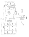
- the generator 100 includes a resonant inverter circuit 102, a pulse width modulation (PWM) controller 110, and a sensor circuit 120.
- the resonant inverter circuit 102 includes an H-bridge 104 having FETs Q1, Q2, Q3, and Q4 and an LCLC tank 106.
- the PWM controller 110 includes a processor 112 and a memory 114.
- the H-bridge 104 is supplied with a positive high voltage direct current (+HVDC).
- the series-parallel, or LCLC, converters of LCLC tank 106 are driven in a full-bridge configuration by the active FET switches Q1, Q2, Q3 and Q4.
- the PWM controller 110 supplies phase-shifted PWM timing signals to FET switches Q1, Q2, Q3 and Q4 as shown in Fig. 2 .
- FETs Q1 and Q2 provide a voltage V S1 to the LCLC tank 106 and FETs Q3 and Q4 provide a voltage V S2 to the LCLC tank 106.
- the LCLC tank 106 outputs electrosurgical energy to an instrument (not shown) via active terminal 130.
- the active terminal 130 provides either continuous or pulsed sinusoidal waveforms of high RF energy.
- the active terminal 130 is configured to provide a plurality of waveforms having various duty cycles, peak voltages, crest factors, and other suitable parameters. Certain types of waveforms are suitable for specific electrosurgical modes.
- the active terminal 130 may provide a 100% duty cycle sinusoidal waveform in cut mode, which is best suited for ablating, fusing and dissecting tissue and a 1-25% duty cycle waveform in coagulation mode, which is best used for cauterizing tissue to stop bleeding.
- a return terminal 132 is coupled to a return pad (not shown) for monopolar procedures.
- the return terminal 132 is electrically coupled to a return electrode (not shown) on an instrument.
- the generator 100 may implement a closed and/or open loop control schemes which include the sensor circuit 120 having a plurality of sensors measuring a variety of tissue and energy properties (e.g., tissue impedance, tissue temperature, output current and/or voltage, etc.) and providing feedback to the PWM controller 110.
- a current sensor 122 can be disposed at either the active or return current path or both and provide an output current (I O ).
- a voltage sensor 124 can sense voltage at the terminals 130 and 132 and provide an output voltage (V O ). The output current (I O ) and the output voltage (V O ) are provided to the sensor circuit 120.
- Sensor circuit 120 may provide the output current and/or the output voltage to the PWM controller 110.
- the PWM controller 110 then transmits appropriate signals to FETs Q1, Q2, Q3, and Q4.
- the PWM controller 110 also receives input signals from the input controls of the generator 100 or the instrument.
- the PWM controller 110 utilizes the input signals to adjust power output by the generator 100 and/or performs other control functions thereon.
- the sensor circuit 120 measures the input voltage (V I ) supplied to the LCLC tank 106, the output voltage (Vo) and output current (I O ) supplied by the active terminal 130 and the return terminal 132 in real time to characterize the electrosurgical process during a procedure. This allows for the measured electrical properties of the generator 100 and/or tissue being subjected to an electrosurgical process to be used as dynamic input control variables to achieve feedback control.
- the sensor circuit 120 may also measure properties of the current and voltage waveforms and determines the shape thereof.
- the input voltage (V I ), the output voltage (V O ), and/or the output current (I O ) are provided to PWM controller 110 to implement a closed loop feedback scheme.
- the processor 112 of the PWM controller 110 may implement an algorithm stored in the memory 114 to adjust the frequency of the PWM timing signals provided to FETs Q1, Q2, Q3, and Q4.
- Generator 100 also includes a switch 134 that allows a user to select one of a plurality of electrosurgical modalities for use during an electrosurgical procedure.
- the electrosurgical modalities may include, e.g., vessel sealing and e-cutting.
- the switch 134 may be any conventional switch having multiple poles that allows a user to select one of the electrosurgical modalities.
- switch 134 may be a touch screen panel to allow a user to select one of the electrosurgical modalities. The operation of switch 134 is described below with reference to Figure 2 .
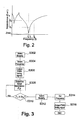
- Fig. 2 illustrates a plot of the output impedance (Z out ) vs. frequency (f).
- the output impedance of the LCLC tank 106 is at its lowest (Z min ).
- the output impedance Z 1 is increased exponentially with respect to the output impedance Z min at f 0 .
- Frequency f 1 is kept above f 0 so that the H-bridge 104 is kept in zero-voltage switching.
- the output impedance Z 2 increases exponentially again with respect to the output impedance at f 1 .
- the LCLC tank 106 is designed so that the gain of the impedance is close to resonance.
- the LCLC tank 106 is designed to have a relatively large "Q" factor.
- the "Q" factor or quality factor of a resonant circuit is a measure of the quality of the circuit. The higher the "Q” factor, the narrower the bandwidth of the LCLC tank 106. Thus, in order to obtain relatively large changes in output impedance with small changes in frequency, the LCLC tank 106 is designed to have a high "Q" factor.
- the components L S , C S , L M and C P of the LCLC tank 106 are selected so that the LCLC tank 106 has a high "Q" factor centered about the frequency f 0 .
- the "Q" factor may greater than 1.
- the user when a user wants to perform a vessel sealing procedure, the user operates switch 134 to select the vessel sealing modality.
- the PWM controller 110 transmits appropriate signals to FETs Q1, Q2, Q3, and Q4 to operate at frequency f 1 so that the output impedance is Z 1 .
- the user If the user wants to perform an e-cutting procedure, the user operates switch 134 to select frequency f 2 so that the output impedance is Z 2 .
- the generator 100 may automatically select a vessel sealing modality or an e-cutting modality.
- Memory 114 may store an algorithm, that when executed by processor 112, controls PWM controller 110 to switch between modalities.
- Switch 134 may be used to select the manual mode as described above or the automatic mode as will be described with reference to Fig. 3 .
- generator 100 selects a modality in step s302.
- the algorithm may initially set generator 100 in a vessel sealing modality or a user may select the vessel sealing modality.
- the processor 112 sets the switching frequency to f 1 in step s304 and the PWM controller 110 outputs the appropriate PWM timing signals to FETs Q1, Q2, Q3, and Q4 to drive H-bridge 104 at switching frequency f 1 (s306).
- the tissue impedance (Z t ) is calculated.
- current sensor 122 and voltage sensor 124 measure the output current (I O ) and output voltage (V O ) and provide the measurements to sensor circuit 120.
- Sensor circuit 120 may process the measurements provided by current sensor 122 and voltage sensor 124 and provide the measurements to PWM controller 110.
- Processor 112 of PWM controller 110 calculates a tissue impedance (Z t ) based on the voltage and current measurements.
- processor 112 compares the tissue impedance (Z t ) to a threshold impedance (Z Th ). If tissue impedance (Z t ) is less than threshold impedance (Z Th ), the algorithm returns to step s308 to determine the tissue impedance (Z t ).
- step s312 the processor 112 selects the e-cutting modality.
- the processor 112 sets the switching frequency to f 2 in step s314 and the PWM controller 110 outputs the appropriate PWM timing signals to FETs Q1, Q2, Q3, and Q4 to drive H-bridge 104 at switching frequency f 2 (s316).
- the initial modality selected in step s302 may be selected based on a measure tissue impedance.
- the PWM controller 110 outputs a test signal to control FETs Q1, Q2, Q3, and Q4 for a predetermined amount of time.
- Sensor circuit 120 receives output current (I O ) and output voltage (V O ) and calculates the tissue impedance. Based on the calculated tissue impedance, the PWM controller 110 selects the appropriate tissue modality.
Landscapes
- Health & Medical Sciences (AREA)
- Surgery (AREA)
- Engineering & Computer Science (AREA)
- Life Sciences & Earth Sciences (AREA)
- Biomedical Technology (AREA)
- Molecular Biology (AREA)
- Nuclear Medicine, Radiotherapy & Molecular Imaging (AREA)
- Plasma & Fusion (AREA)
- Physics & Mathematics (AREA)
- Heart & Thoracic Surgery (AREA)
- Medical Informatics (AREA)
- Otolaryngology (AREA)
- Animal Behavior & Ethology (AREA)
- General Health & Medical Sciences (AREA)
- Public Health (AREA)
- Veterinary Medicine (AREA)
- Surgical Instruments (AREA)
- Amplifiers (AREA)
- Inverter Devices (AREA)
Applications Claiming Priority (2)
| Application Number | Priority Date | Filing Date | Title |
|---|---|---|---|
| US201361891805P | 2013-10-16 | 2013-10-16 | |
| US14/445,745 US10105172B2 (en) | 2013-10-16 | 2014-07-29 | Radiofrequency amplifier impedance optimization |
Publications (3)
| Publication Number | Publication Date |
|---|---|
| EP2862532A2 true EP2862532A2 (de) | 2015-04-22 |
| EP2862532A3 EP2862532A3 (de) | 2015-11-25 |
| EP2862532B1 EP2862532B1 (de) | 2020-07-01 |
Family
ID=51687780
Family Applications (1)
| Application Number | Title | Priority Date | Filing Date |
|---|---|---|---|
| EP14185719.3A Active EP2862532B1 (de) | 2013-10-16 | 2014-09-22 | Funkfrequenzverstärker-Impedanzoptimierung |
Country Status (3)
| Country | Link |
|---|---|
| US (1) | US10105172B2 (de) |
| EP (1) | EP2862532B1 (de) |
| CN (1) | CN204169923U (de) |
Families Citing this family (12)
| Publication number | Priority date | Publication date | Assignee | Title |
|---|---|---|---|---|
| DE102015212546A1 (de) * | 2015-07-03 | 2017-01-05 | Olympus Winter & Ibe Gmbh | Hochfrequenzgenerator zum Anschluss elektrochirurgischer Instrumente |
| US11446078B2 (en) | 2015-07-20 | 2022-09-20 | Megadyne Medical Products, Inc. | Electrosurgical wave generator |
| CN105496549A (zh) * | 2015-10-29 | 2016-04-20 | 绵阳立德电子股份有限公司 | 一种射频发生器及利用该射频器产生射频能量的方法 |
| CN113573655B (zh) | 2019-03-15 | 2025-05-27 | 波士顿科学国际有限公司 | 用于选择性细胞消融的空间复用波形 |
| CN113853174B (zh) | 2019-03-15 | 2024-10-11 | 波士顿科学国际有限公司 | 用于选择性细胞消融的时间多路复用波形 |
| WO2020190693A1 (en) | 2019-03-15 | 2020-09-24 | Boston Scientific Scimed, Inc. | Waveform generator and control for selective cell ablation |
| CN114945338A (zh) | 2019-10-15 | 2022-08-26 | 波士顿科学国际有限公司 | 用于消融系统的控制系统和用户界面 |
| US11992260B2 (en) | 2020-03-31 | 2024-05-28 | Boston Scientific Scimed, Inc. | Smart probe identification for ablation modalities |
| EP4066766B1 (de) * | 2021-03-31 | 2023-09-06 | Erbe Elektromedizin GmbH | Elektromedizinischer leistungsgenerator |
| PL4124310T3 (pl) * | 2021-07-26 | 2024-02-19 | Erbe Elektromedizin Gmbh | Generator z odzyskiwaniem energii |
| EP4522050A4 (de) * | 2022-05-10 | 2026-04-15 | Eximis Surgical Inc | Systeme, verfahren und vorrichtungen für einen elektrochirurgischen hf-generator zum elektrochirurgischen schneiden |
| DE102022127935A1 (de) * | 2022-10-21 | 2024-05-02 | Karl Storz Se & Co. Kg | Elektrochirurgische Vorrichtung, System und Verfahren zur Steuerung einer elektrochirurgischen Vorrichtung |
Family Cites Families (87)
| Publication number | Priority date | Publication date | Assignee | Title |
|---|---|---|---|---|
| DE179607C (de) | 1906-11-12 | |||
| DE390937C (de) | 1922-10-13 | 1924-03-03 | Adolf Erb | Vorrichtung zur Innenbeheizung von Wannenoefen zum Haerten, Anlassen, Gluehen, Vergueten und Schmelzen |
| DE1099658B (de) | 1959-04-29 | 1961-02-16 | Siemens Reiniger Werke Ag | Selbsttaetige Einschaltvorrichtung fuer Hochfrequenzchirurgiegeraete |
| FR1275415A (fr) | 1960-09-26 | 1961-11-10 | Dispositif détecteur de perturbations pour installations électriques, notamment d'électrochirurgie | |
| DE1139927B (de) | 1961-01-03 | 1962-11-22 | Friedrich Laber | Hochfrequenz-Chirurgiegeraet |
| DE1149832C2 (de) | 1961-02-25 | 1977-10-13 | Siemens AG, 1000 Berlin und 8000 München | Hochfrequenz-chirurgieapparat |
| FR1347865A (fr) | 1962-11-22 | 1964-01-04 | Perfectionnements aux appareils de diathermo-coagulation | |
| DE1439302B2 (de) | 1963-10-26 | 1971-05-19 | Siemens AG, 1000 Berlin u 8000 München | Hochfrequenz Chirurgiegerat |
| GB1480736A (en) | 1973-08-23 | 1977-07-20 | Matburn Ltd | Electrodiathermy apparatus |
| DE2455174A1 (de) | 1973-11-21 | 1975-05-22 | Termiflex Corp | Ein/ausgabegeraet zum datenaustausch mit datenverarbeitungseinrichtungen |
| DE2407559C3 (de) | 1974-02-16 | 1982-01-21 | Dornier System Gmbh, 7990 Friedrichshafen | Wärmesonde |
| US4237887A (en) | 1975-01-23 | 1980-12-09 | Valleylab, Inc. | Electrosurgical device |
| DE2504280C3 (de) | 1975-02-01 | 1980-08-28 | Hans Heinrich Prof. Dr. 8035 Gauting Meinke | Vorrichtung zum Schneiden und/oder Koagulieren menschlichen Gewebes mit Hochfrequenzstrom |
| CA1064581A (en) | 1975-06-02 | 1979-10-16 | Stephen W. Andrews | Pulse control circuit and method for electrosurgical units |
| DE2540968C2 (de) | 1975-09-13 | 1982-12-30 | Erbe Elektromedizin GmbH, 7400 Tübingen | Einrichtung zum Einschalten des Koagulationsstroms einer bipolaren Koagulationspinzette |
| US4094320A (en) | 1976-09-09 | 1978-06-13 | Valleylab, Inc. | Electrosurgical safety circuit and method of using same |
| FR2390968A1 (fr) | 1977-05-16 | 1978-12-15 | Skovajsa Joseph | Dispositif de traitement local d'un patient, notamment pour acupuncture ou auriculotherapie |
| SU727201A2 (ru) | 1977-11-02 | 1980-04-15 | Киевский Научно-Исследовательский Институт Нейрохирургии | Электрохирургический аппарат |
| DE2803275C3 (de) | 1978-01-26 | 1980-09-25 | Aesculap-Werke Ag Vormals Jetter & Scheerer, 7200 Tuttlingen | Fernschalteinrichtung zum Schalten eines monopolaren HF-Chirurgiegerätes |
| DE2823291A1 (de) | 1978-05-27 | 1979-11-29 | Rainer Ing Grad Koch | Schaltung zur automatischen einschaltung des hochfrequenzstromes von hochfrequenz-koagulationsgeraeten |
| DE2946728A1 (de) | 1979-11-20 | 1981-05-27 | Erbe Elektromedizin GmbH & Co KG, 7400 Tübingen | Hochfrequenz-chirurgiegeraet |
| JPS5778844A (en) | 1980-11-04 | 1982-05-17 | Kogyo Gijutsuin | Lasre knife |
| DE3045996A1 (de) | 1980-12-05 | 1982-07-08 | Medic Eschmann Handelsgesellschaft für medizinische Instrumente mbH, 2000 Hamburg | Elektro-chirurgiegeraet |
| FR2502935B1 (fr) | 1981-03-31 | 1985-10-04 | Dolley Roger | Procede et dispositif de controle de la coagulation de tissus a l'aide d'un courant a haute frequence |
| DE3120102A1 (de) | 1981-05-20 | 1982-12-09 | F.L. Fischer GmbH & Co, 7800 Freiburg | Anordnung zur hochfrequenzkoagulation von eiweiss fuer chirurgische zwecke |
| US4429694A (en) | 1981-07-06 | 1984-02-07 | C. R. Bard, Inc. | Electrosurgical generator |
| FR2517953A1 (fr) | 1981-12-10 | 1983-06-17 | Alvar Electronic | Appareil diaphanometre et son procede d'utilisation |
| JPS6064765A (ja) | 1983-09-16 | 1985-04-13 | Daihen Corp | 溶接用電源装置 |
| FR2573301B3 (fr) | 1984-11-16 | 1987-04-30 | Lamidey Gilles | Pince chirurgicale et son appareillage de commande et de controle |
| DE3510586A1 (de) | 1985-03-23 | 1986-10-02 | Erbe Elektromedizin GmbH, 7400 Tübingen | Kontrolleinrichtung fuer ein hochfrequenz-chirurgiegeraet |
| DE3604823C2 (de) | 1986-02-15 | 1995-06-01 | Lindenmeier Heinz | Hochfrequenzgenerator mit automatischer Leistungsregelung für die Hochfrequenzchirurgie |
| EP0246350A1 (de) | 1986-05-23 | 1987-11-25 | Erbe Elektromedizin GmbH. | Koagulationselektrode |
| JPS635876A (ja) | 1986-06-27 | 1988-01-11 | Hitachi Seiko Ltd | ア−ク溶接機 |
| DE3638748A1 (de) | 1986-11-13 | 1988-06-01 | Hirschmann Radiotechnik | Kapazitives trennglied |
| US5073167A (en) | 1987-06-26 | 1991-12-17 | M/A-Com, Inc. | In-line microwave warming apparatus |
| US4931047A (en) | 1987-09-30 | 1990-06-05 | Cavitron, Inc. | Method and apparatus for providing enhanced tissue fragmentation and/or hemostasis |
| EP0325456B1 (de) | 1988-01-20 | 1995-12-27 | G2 Design Limited | Diathermiegerät |
| EP0336742A3 (de) | 1988-04-08 | 1990-05-16 | Bristol-Myers Company | Methode und Gerät zur Eichung eines elektrochirugischen Gerätes |
| DE3904558C2 (de) | 1989-02-15 | 1997-09-18 | Lindenmeier Heinz | Automatisch leistungsgeregelter Hochfrequenzgenerator für die Hochfrequenz-Chirurgie |
| DE58908600D1 (de) | 1989-04-01 | 1994-12-08 | Erbe Elektromedizin | Einrichtung zur Überwachung der Applikation von Neutralelektroden bei der Hochfrequenzchirurgie. |
| DE3942998C2 (de) | 1989-12-27 | 1998-11-26 | Delma Elektro Med App | Elektrochirurgisches Hochfrequenzgerät |
| US5173643A (en) | 1990-06-25 | 1992-12-22 | Lutron Electronics Co., Inc. | Circuit for dimming compact fluorescent lamps |
| DE4205213A1 (de) | 1992-02-20 | 1993-08-26 | Delma Elektro Med App | Hochfrequenzchirurgiegeraet |
| DE4206433A1 (de) | 1992-02-29 | 1993-09-02 | Bosch Gmbh Robert | Kapazitives trennstueck |
| US5348554A (en) | 1992-12-01 | 1994-09-20 | Cardiac Pathways Corporation | Catheter for RF ablation with cooled electrode |
| DE4339049C2 (de) | 1993-11-16 | 2001-06-28 | Erbe Elektromedizin | Einrichtung zur Konfiguration chirurgischer Systeme |
| DE19506363A1 (de) | 1995-02-24 | 1996-08-29 | Frost Lore Geb Haupt | Verfahren zur nicht-invasiven Thermometrie in Organen unter medizinischen Hyperthermie- und Koagulationsbedingungen |
| US5837001A (en) | 1995-12-08 | 1998-11-17 | C. R. Bard | Radio frequency energy delivery system for multipolar electrode catheters |
| WO1998015317A1 (en) | 1996-10-07 | 1998-04-16 | Sulzer Intermedics Inc. | Controllable drug injection electrode |
| DE19643127A1 (de) | 1996-10-18 | 1998-04-23 | Berchtold Gmbh & Co Geb | Hochfrequenzchirurgiegerät und Verfahren zu dessen Betrieb |
| GB9626512D0 (en) | 1996-12-20 | 1997-02-05 | Gyrus Medical Ltd | An improved electrosurgical generator and system |
| DE19717411A1 (de) | 1997-04-25 | 1998-11-05 | Aesculap Ag & Co Kg | Verfahren und Vorrichtung zur Überwachung der thermischen Belastung des Gewebes eines Patienten |
| US5838558A (en) | 1997-05-19 | 1998-11-17 | Trw Inc. | Phase staggered full-bridge converter with soft-PWM switching |
| EP0882955B1 (de) | 1997-06-06 | 2005-04-06 | Endress + Hauser GmbH + Co. KG | Mit Mikrowellen arbeitendes Füllstandsmessgerät |
| US6493588B1 (en) | 1998-03-18 | 2002-12-10 | Mmc/Gatx Partnership No. 1 | Electro-nerve stimulator systems and methods |
| DE19848540A1 (de) | 1998-10-21 | 2000-05-25 | Reinhard Kalfhaus | Schaltungsanordnung und Verfahren zum Betreiben eines Wechselrichters |
| US6582427B1 (en) * | 1999-03-05 | 2003-06-24 | Gyrus Medical Limited | Electrosurgery system |
| US6203541B1 (en) | 1999-04-23 | 2001-03-20 | Sherwood Services Ag | Automatic activation of electrosurgical generator bipolar output |
| JP4667709B2 (ja) | 2000-08-08 | 2011-04-13 | エルベ エレクトロメディツィン ゲーエムベーハー | 許容電力量を調整できる高周波外科手術用高周波発生器および許容電力の制御方法 |
| JP4499893B2 (ja) | 2000-08-23 | 2010-07-07 | オリンパス株式会社 | 電気手術装置 |
| DE10061278B4 (de) | 2000-12-08 | 2004-09-16 | GFD-Gesellschaft für Diamantprodukte mbH | Instrument für chirurgische Zwecke |
| US8133218B2 (en) | 2000-12-28 | 2012-03-13 | Senorx, Inc. | Electrosurgical medical system and method |
| DE10218895B4 (de) | 2002-04-26 | 2006-12-21 | Storz Endoskop Produktions Gmbh | Hochfrequenz-Chirurgiegenerator |
| US6939347B2 (en) | 2002-11-19 | 2005-09-06 | Conmed Corporation | Electrosurgical generator and method with voltage and frequency regulated high-voltage current mode power supply |
| DE60314184T2 (de) | 2003-01-09 | 2008-01-24 | Gyrus Medical Ltd., St. Mellons | Elektrochirurgischer generator |
| JP2005185657A (ja) | 2003-12-26 | 2005-07-14 | Olympus Corp | 外科用処置具 |
| US7456518B2 (en) | 2004-08-31 | 2008-11-25 | American Power Conversion Corporation | Method and apparatus for providing uninterruptible power |
| DE102004054575A1 (de) | 2004-11-11 | 2006-05-24 | Erbe Elektromedizin Gmbh | Regelung für ein HF-Chirurgiegerät |
| ES2383376T3 (es) * | 2005-01-18 | 2012-06-20 | Alma Lasers Ltd | Sistema mejorado para calentar tejido biológico mediante energía de RF |
| US8603083B2 (en) * | 2005-07-15 | 2013-12-10 | Atricure, Inc. | Matrix router for surgical ablation |
| US8734438B2 (en) | 2005-10-21 | 2014-05-27 | Covidien Ag | Circuit and method for reducing stored energy in an electrosurgical generator |
| WO2008053532A1 (en) | 2006-10-31 | 2008-05-08 | Olympus Medical Systems Corp. | High frequency cautery electric power source device |
| USD574323S1 (en) | 2007-02-12 | 2008-08-05 | Tyco Healthcare Group Lp | Generator |
| US8801703B2 (en) | 2007-08-01 | 2014-08-12 | Covidien Lp | System and method for return electrode monitoring |
| JP2009081183A (ja) | 2007-09-25 | 2009-04-16 | Murata Mfg Co Ltd | 配線基板の製造方法 |
| US8298226B2 (en) * | 2008-05-23 | 2012-10-30 | Gyrus Medical Limited | Electrosurgical generator and system |
| US8398627B2 (en) | 2008-05-23 | 2013-03-19 | Gyrus Medical Limited | Electrosurgical generator and system |
| DE102008058737B4 (de) | 2008-09-08 | 2019-12-12 | Erbe Elektromedizin Gmbh | HF-Chirurgiegenerator |
| US8107254B2 (en) | 2008-11-20 | 2012-01-31 | International Business Machines Corporation | Integrating capacitors into vias of printed circuit boards |
| US8610501B2 (en) | 2009-11-16 | 2013-12-17 | Covidien Lp | Class resonant-H electrosurgical generators |
| GB2480498A (en) | 2010-05-21 | 2011-11-23 | Ethicon Endo Surgery Inc | Medical device comprising RF circuitry |
| US8968297B2 (en) | 2011-07-19 | 2015-03-03 | Covidien Lp | Microwave and RF ablation system and related method for dynamic impedance matching |
| CN104136262A (zh) | 2012-02-23 | 2014-11-05 | 丰田自动车株式会社 | 电动车 |
| US9113887B2 (en) | 2012-04-10 | 2015-08-25 | Covidien Lp | Electrosurgical generator |
| US9449746B2 (en) | 2012-10-17 | 2016-09-20 | Covidien Lp | Methods of manufacturing planar transformers |
| US9921243B2 (en) | 2012-12-17 | 2018-03-20 | Covidien Lp | System and method for voltage and current sensing |
| US9872719B2 (en) | 2013-07-24 | 2018-01-23 | Covidien Lp | Systems and methods for generating electrosurgical energy using a multistage power converter |
-
2014
- 2014-07-29 US US14/445,745 patent/US10105172B2/en active Active
- 2014-09-22 EP EP14185719.3A patent/EP2862532B1/de active Active
- 2014-10-09 CN CN201420580790.0U patent/CN204169923U/zh not_active Expired - Fee Related
Non-Patent Citations (1)
| Title |
|---|
| None |
Also Published As
| Publication number | Publication date |
|---|---|
| CN204169923U (zh) | 2015-02-25 |
| EP2862532A3 (de) | 2015-11-25 |
| US10105172B2 (en) | 2018-10-23 |
| US20150105766A1 (en) | 2015-04-16 |
| EP2862532B1 (de) | 2020-07-01 |
Similar Documents
| Publication | Publication Date | Title |
|---|---|---|
| AU2018241133B2 (en) | Dead-time optimization of resonant inverters | |
| EP2862532B1 (de) | Funkfrequenzverstärker-Impedanzoptimierung | |
| US9522038B2 (en) | Crest factor enhancement in electrosurgical generators | |
| US10898257B2 (en) | Resonant inverter with a common mode choke | |
| US9585709B2 (en) | Square wave for vessel sealing | |
| US9770283B2 (en) | Systems and methods for improving efficiency of electrosurgical generators | |
| US9839469B2 (en) | Systems and methods for improving efficiency of electrosurgical generators | |
| US10646266B2 (en) | System and method for return electrode monitoring | |
| CN104287822A (zh) | 具有连续和任意可变的峰值因数的电外科发生器 | |
| AU2014218371B2 (en) | Systems and methods for improving efficiency of electrosurgical generators | |
| US9522039B2 (en) | Crest factor enhancement in electrosurgical generators | |
| US20160030104A1 (en) | Methods for improving high frequency leakage of electrosurgical generators |
Legal Events
| Date | Code | Title | Description |
|---|---|---|---|
| PUAI | Public reference made under article 153(3) epc to a published international application that has entered the european phase |
Free format text: ORIGINAL CODE: 0009012 |
|
| 17P | Request for examination filed |
Effective date: 20140922 |
|
| AK | Designated contracting states |
Kind code of ref document: A2 Designated state(s): AL AT BE BG CH CY CZ DE DK EE ES FI FR GB GR HR HU IE IS IT LI LT LU LV MC MK MT NL NO PL PT RO RS SE SI SK SM TR |
|
| AX | Request for extension of the european patent |
Extension state: BA ME |
|
| RIC1 | Information provided on ipc code assigned before grant |
Ipc: A61B 18/12 20060101AFI20150529BHEP Ipc: H02M 7/5387 20070101ALN20150529BHEP Ipc: H02M 7/48 20070101ALN20150529BHEP |
|
| PUAL | Search report despatched |
Free format text: ORIGINAL CODE: 0009013 |
|
| AK | Designated contracting states |
Kind code of ref document: A3 Designated state(s): AL AT BE BG CH CY CZ DE DK EE ES FI FR GB GR HR HU IE IS IT LI LT LU LV MC MK MT NL NO PL PT RO RS SE SI SK SM TR |
|
| AX | Request for extension of the european patent |
Extension state: BA ME |
|
| RIC1 | Information provided on ipc code assigned before grant |
Ipc: H02M 7/48 20070101ALN20151022BHEP Ipc: H02M 7/5387 20070101ALN20151022BHEP Ipc: A61B 18/12 20060101AFI20151022BHEP |
|
| R17P | Request for examination filed (corrected) |
Effective date: 20160520 |
|
| RBV | Designated contracting states (corrected) |
Designated state(s): AL AT BE BG CH CY CZ DE DK EE ES FI FR GB GR HR HU IE IS IT LI LT LU LV MC MK MT NL NO PL PT RO RS SE SI SK SM TR |
|
| RIN1 | Information on inventor provided before grant (corrected) |
Inventor name: JOHNSON, JOSHUA H. Inventor name: GILBERT, JAMES A. |
|
| STAA | Information on the status of an ep patent application or granted ep patent |
Free format text: STATUS: EXAMINATION IS IN PROGRESS |
|
| 17Q | First examination report despatched |
Effective date: 20190111 |
|
| GRAP | Despatch of communication of intention to grant a patent |
Free format text: ORIGINAL CODE: EPIDOSNIGR1 |
|
| STAA | Information on the status of an ep patent application or granted ep patent |
Free format text: STATUS: GRANT OF PATENT IS INTENDED |
|
| RIC1 | Information provided on ipc code assigned before grant |
Ipc: H02M 7/48 20070101ALN20200115BHEP Ipc: A61B 18/12 20060101AFI20200115BHEP Ipc: H02M 7/5387 20070101ALN20200115BHEP |
|
| RIC1 | Information provided on ipc code assigned before grant |
Ipc: H02M 7/5387 20070101ALN20200123BHEP Ipc: H02M 7/48 20070101ALN20200123BHEP Ipc: A61B 18/12 20060101AFI20200123BHEP |
|
| INTG | Intention to grant announced |
Effective date: 20200206 |
|
| GRAS | Grant fee paid |
Free format text: ORIGINAL CODE: EPIDOSNIGR3 |
|
| GRAA | (expected) grant |
Free format text: ORIGINAL CODE: 0009210 |
|
| STAA | Information on the status of an ep patent application or granted ep patent |
Free format text: STATUS: THE PATENT HAS BEEN GRANTED |
|
| AK | Designated contracting states |
Kind code of ref document: B1 Designated state(s): AL AT BE BG CH CY CZ DE DK EE ES FI FR GB GR HR HU IE IS IT LI LT LU LV MC MK MT NL NO PL PT RO RS SE SI SK SM TR |
|
| REG | Reference to a national code |
Ref country code: CH Ref legal event code: EP Ref country code: AT Ref legal event code: REF Ref document number: 1285403 Country of ref document: AT Kind code of ref document: T Effective date: 20200715 |
|
| REG | Reference to a national code |
Ref country code: IE Ref legal event code: FG4D |
|
| REG | Reference to a national code |
Ref country code: DE Ref legal event code: R096 Ref document number: 602014067182 Country of ref document: DE |
|
| REG | Reference to a national code |
Ref country code: LT Ref legal event code: MG4D |
|
| PG25 | Lapsed in a contracting state [announced via postgrant information from national office to epo] |
Ref country code: BG Free format text: LAPSE BECAUSE OF FAILURE TO SUBMIT A TRANSLATION OF THE DESCRIPTION OR TO PAY THE FEE WITHIN THE PRESCRIBED TIME-LIMIT Effective date: 20201001 |
|
| REG | Reference to a national code |
Ref country code: NL Ref legal event code: MP Effective date: 20200701 |
|
| REG | Reference to a national code |
Ref country code: AT Ref legal event code: MK05 Ref document number: 1285403 Country of ref document: AT Kind code of ref document: T Effective date: 20200701 |
|
| PG25 | Lapsed in a contracting state [announced via postgrant information from national office to epo] |
Ref country code: ES Free format text: LAPSE BECAUSE OF FAILURE TO SUBMIT A TRANSLATION OF THE DESCRIPTION OR TO PAY THE FEE WITHIN THE PRESCRIBED TIME-LIMIT Effective date: 20200701 Ref country code: SE Free format text: LAPSE BECAUSE OF FAILURE TO SUBMIT A TRANSLATION OF THE DESCRIPTION OR TO PAY THE FEE WITHIN THE PRESCRIBED TIME-LIMIT Effective date: 20200701 Ref country code: AT Free format text: LAPSE BECAUSE OF FAILURE TO SUBMIT A TRANSLATION OF THE DESCRIPTION OR TO PAY THE FEE WITHIN THE PRESCRIBED TIME-LIMIT Effective date: 20200701 Ref country code: NO Free format text: LAPSE BECAUSE OF FAILURE TO SUBMIT A TRANSLATION OF THE DESCRIPTION OR TO PAY THE FEE WITHIN THE PRESCRIBED TIME-LIMIT Effective date: 20201001 Ref country code: GR Free format text: LAPSE BECAUSE OF FAILURE TO SUBMIT A TRANSLATION OF THE DESCRIPTION OR TO PAY THE FEE WITHIN THE PRESCRIBED TIME-LIMIT Effective date: 20201002 Ref country code: FI Free format text: LAPSE BECAUSE OF FAILURE TO SUBMIT A TRANSLATION OF THE DESCRIPTION OR TO PAY THE FEE WITHIN THE PRESCRIBED TIME-LIMIT Effective date: 20200701 Ref country code: HR Free format text: LAPSE BECAUSE OF FAILURE TO SUBMIT A TRANSLATION OF THE DESCRIPTION OR TO PAY THE FEE WITHIN THE PRESCRIBED TIME-LIMIT Effective date: 20200701 Ref country code: LT Free format text: LAPSE BECAUSE OF FAILURE TO SUBMIT A TRANSLATION OF THE DESCRIPTION OR TO PAY THE FEE WITHIN THE PRESCRIBED TIME-LIMIT Effective date: 20200701 Ref country code: PT Free format text: LAPSE BECAUSE OF FAILURE TO SUBMIT A TRANSLATION OF THE DESCRIPTION OR TO PAY THE FEE WITHIN THE PRESCRIBED TIME-LIMIT Effective date: 20201102 Ref country code: CZ Free format text: LAPSE BECAUSE OF FAILURE TO SUBMIT A TRANSLATION OF THE DESCRIPTION OR TO PAY THE FEE WITHIN THE PRESCRIBED TIME-LIMIT Effective date: 20200701 |
|
| PG25 | Lapsed in a contracting state [announced via postgrant information from national office to epo] |
Ref country code: LV Free format text: LAPSE BECAUSE OF FAILURE TO SUBMIT A TRANSLATION OF THE DESCRIPTION OR TO PAY THE FEE WITHIN THE PRESCRIBED TIME-LIMIT Effective date: 20200701 Ref country code: PL Free format text: LAPSE BECAUSE OF FAILURE TO SUBMIT A TRANSLATION OF THE DESCRIPTION OR TO PAY THE FEE WITHIN THE PRESCRIBED TIME-LIMIT Effective date: 20200701 Ref country code: RS Free format text: LAPSE BECAUSE OF FAILURE TO SUBMIT A TRANSLATION OF THE DESCRIPTION OR TO PAY THE FEE WITHIN THE PRESCRIBED TIME-LIMIT Effective date: 20200701 Ref country code: IS Free format text: LAPSE BECAUSE OF FAILURE TO SUBMIT A TRANSLATION OF THE DESCRIPTION OR TO PAY THE FEE WITHIN THE PRESCRIBED TIME-LIMIT Effective date: 20201101 |
|
| PG25 | Lapsed in a contracting state [announced via postgrant information from national office to epo] |
Ref country code: NL Free format text: LAPSE BECAUSE OF FAILURE TO SUBMIT A TRANSLATION OF THE DESCRIPTION OR TO PAY THE FEE WITHIN THE PRESCRIBED TIME-LIMIT Effective date: 20200701 |
|
| REG | Reference to a national code |
Ref country code: DE Ref legal event code: R097 Ref document number: 602014067182 Country of ref document: DE |
|
| PG25 | Lapsed in a contracting state [announced via postgrant information from national office to epo] |
Ref country code: MC Free format text: LAPSE BECAUSE OF FAILURE TO SUBMIT A TRANSLATION OF THE DESCRIPTION OR TO PAY THE FEE WITHIN THE PRESCRIBED TIME-LIMIT Effective date: 20200701 Ref country code: RO Free format text: LAPSE BECAUSE OF FAILURE TO SUBMIT A TRANSLATION OF THE DESCRIPTION OR TO PAY THE FEE WITHIN THE PRESCRIBED TIME-LIMIT Effective date: 20200701 Ref country code: SM Free format text: LAPSE BECAUSE OF FAILURE TO SUBMIT A TRANSLATION OF THE DESCRIPTION OR TO PAY THE FEE WITHIN THE PRESCRIBED TIME-LIMIT Effective date: 20200701 Ref country code: IT Free format text: LAPSE BECAUSE OF FAILURE TO SUBMIT A TRANSLATION OF THE DESCRIPTION OR TO PAY THE FEE WITHIN THE PRESCRIBED TIME-LIMIT Effective date: 20200701 Ref country code: DK Free format text: LAPSE BECAUSE OF FAILURE TO SUBMIT A TRANSLATION OF THE DESCRIPTION OR TO PAY THE FEE WITHIN THE PRESCRIBED TIME-LIMIT Effective date: 20200701 Ref country code: EE Free format text: LAPSE BECAUSE OF FAILURE TO SUBMIT A TRANSLATION OF THE DESCRIPTION OR TO PAY THE FEE WITHIN THE PRESCRIBED TIME-LIMIT Effective date: 20200701 |
|
| REG | Reference to a national code |
Ref country code: CH Ref legal event code: PL |
|
| PLBE | No opposition filed within time limit |
Free format text: ORIGINAL CODE: 0009261 |
|
| STAA | Information on the status of an ep patent application or granted ep patent |
Free format text: STATUS: NO OPPOSITION FILED WITHIN TIME LIMIT |
|
| PG25 | Lapsed in a contracting state [announced via postgrant information from national office to epo] |
Ref country code: AL Free format text: LAPSE BECAUSE OF FAILURE TO SUBMIT A TRANSLATION OF THE DESCRIPTION OR TO PAY THE FEE WITHIN THE PRESCRIBED TIME-LIMIT Effective date: 20200701 |
|
| 26N | No opposition filed |
Effective date: 20210406 |
|
| REG | Reference to a national code |
Ref country code: BE Ref legal event code: MM Effective date: 20200930 |
|
| GBPC | Gb: european patent ceased through non-payment of renewal fee |
Effective date: 20201001 |
|
| PG25 | Lapsed in a contracting state [announced via postgrant information from national office to epo] |
Ref country code: LU Free format text: LAPSE BECAUSE OF NON-PAYMENT OF DUE FEES Effective date: 20200922 Ref country code: SK Free format text: LAPSE BECAUSE OF FAILURE TO SUBMIT A TRANSLATION OF THE DESCRIPTION OR TO PAY THE FEE WITHIN THE PRESCRIBED TIME-LIMIT Effective date: 20200701 |
|
| PG25 | Lapsed in a contracting state [announced via postgrant information from national office to epo] |
Ref country code: BE Free format text: LAPSE BECAUSE OF NON-PAYMENT OF DUE FEES Effective date: 20200930 Ref country code: CH Free format text: LAPSE BECAUSE OF NON-PAYMENT OF DUE FEES Effective date: 20200930 Ref country code: LI Free format text: LAPSE BECAUSE OF NON-PAYMENT OF DUE FEES Effective date: 20200930 Ref country code: GB Free format text: LAPSE BECAUSE OF NON-PAYMENT OF DUE FEES Effective date: 20201001 Ref country code: IE Free format text: LAPSE BECAUSE OF NON-PAYMENT OF DUE FEES Effective date: 20200922 Ref country code: SI Free format text: LAPSE BECAUSE OF FAILURE TO SUBMIT A TRANSLATION OF THE DESCRIPTION OR TO PAY THE FEE WITHIN THE PRESCRIBED TIME-LIMIT Effective date: 20200701 |
|
| PGFP | Annual fee paid to national office [announced via postgrant information from national office to epo] |
Ref country code: FR Payment date: 20210819 Year of fee payment: 8 |
|
| PGFP | Annual fee paid to national office [announced via postgrant information from national office to epo] |
Ref country code: DE Payment date: 20210818 Year of fee payment: 8 |
|
| PG25 | Lapsed in a contracting state [announced via postgrant information from national office to epo] |
Ref country code: TR Free format text: LAPSE BECAUSE OF FAILURE TO SUBMIT A TRANSLATION OF THE DESCRIPTION OR TO PAY THE FEE WITHIN THE PRESCRIBED TIME-LIMIT Effective date: 20200701 Ref country code: MT Free format text: LAPSE BECAUSE OF FAILURE TO SUBMIT A TRANSLATION OF THE DESCRIPTION OR TO PAY THE FEE WITHIN THE PRESCRIBED TIME-LIMIT Effective date: 20200701 Ref country code: CY Free format text: LAPSE BECAUSE OF FAILURE TO SUBMIT A TRANSLATION OF THE DESCRIPTION OR TO PAY THE FEE WITHIN THE PRESCRIBED TIME-LIMIT Effective date: 20200701 |
|
| PG25 | Lapsed in a contracting state [announced via postgrant information from national office to epo] |
Ref country code: MK Free format text: LAPSE BECAUSE OF FAILURE TO SUBMIT A TRANSLATION OF THE DESCRIPTION OR TO PAY THE FEE WITHIN THE PRESCRIBED TIME-LIMIT Effective date: 20200701 |
|
| REG | Reference to a national code |
Ref country code: DE Ref legal event code: R119 Ref document number: 602014067182 Country of ref document: DE |
|
| PG25 | Lapsed in a contracting state [announced via postgrant information from national office to epo] |
Ref country code: FR Free format text: LAPSE BECAUSE OF NON-PAYMENT OF DUE FEES Effective date: 20220930 Ref country code: DE Free format text: LAPSE BECAUSE OF NON-PAYMENT OF DUE FEES Effective date: 20230401 |